Embed Size (px)
Citation preview
Installation instructions available at www.greenheck.com
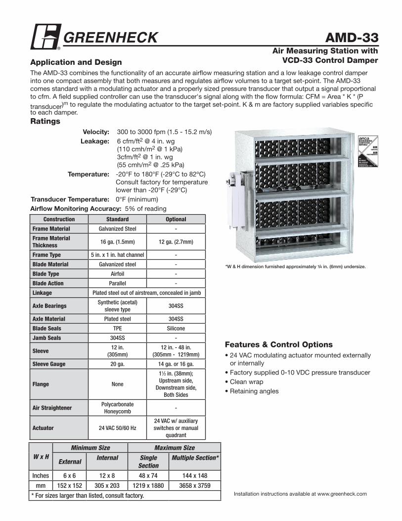
*W & H dimension furnished approximately 1/4 in. (6mm) undersize.
AMD-33
W x HMinimum Size Maximum Size
External Internal Single Section
Multiple Section*
Inches 6 x 6 12 x 8 48 x 74 144 x 148
mm 152 x 152 305 x 203 1219 x 1880 3658 x 3759
* For sizes larger than listed, consult factory.
Construction Standard Optional
Frame Material Galvanized Steel -
Frame Material Thickness 16 ga. (1.5mm) 12 ga. (2.7mm)
Frame Type 5 in. x 1 in. hat channel -
Blade Material Galvanized steel -
Blade Type Airfoil -
Blade Action Parallel -
Linkage Plated steel out of airstream, concealed in jamb
Axle Bearings Synthetic (acetal) sleeve type
304SS
Axle Material Plated steel 304SS
Blade Seals TPE Silicone
Jamb Seals 304SS -
Sleeve 12 in.(305mm)
12 in. - 48 in. (305mm - 1219mm)
Sleeve Gauge 20 ga. 14 ga. or 16 ga.
Flange None
11⁄2 in. (38mm); Upstream side,
Downstream side, Both Sides
Air Straightener Polycarbonate Honeycomb
-
Actuator 24 VAC 50/60 Hz24 VAC w/ auxiliary switches or manual
quadrant
Application and DesignThe AMD-33 combines the functionality of an accurate airflow measuring station and a low leakage control damper into one compact assembly that both measures and regulates airflow volumes to a target set-point. The AMD-33 comes standard with a modulating actuator and a properly sized pressure transducer that output a signal proportional to cfm. A field supplied controller can use the transducer's signal along with the flow formula: CFM = Area * K * (P transducer)
m to regulate the modulating actuator to the target set-point. K & m are factory supplied variables specific to each damper.
Air Measuring Station with VCD-33 Control Damper
Features & Control Options• 24 VAC modulating actuator mounted externally
or internally• Factory supplied 0-10 VDC pressure transducer• Clean wrap• Retaining angles
Ratings Velocity: 300 to 3000 fpm (1.5 - 15.2 m/s) Leakage: 6 cfm/ft2 @ 4 in. wg (110 cmh/m2 @ 1 kPa) 3cfm/ft2 @ 1 in. wg (55 cmh/m2 @ .25 kPa) Temperature: -20°F to 180°F (-29°C to 82ºC)
Consult factory for temperature lower than -20°F (-29°C)
Transducer Temperature: 0°F (minimum)Airflow Monitoring Accuracy: 5% of reading
Greenheck Fan Corporation certifies that the model AMD-33 shown herein is licensed to bear the AMCA Seal. The ratings shown are based on tests and procedures performed in accordance with AMCA Publication 511 and comply with the requirements of the AMCA Certified Ratings Programs.The AMCA Certified Ratings Seal applies to Air Leakage and Air Performance ratings.
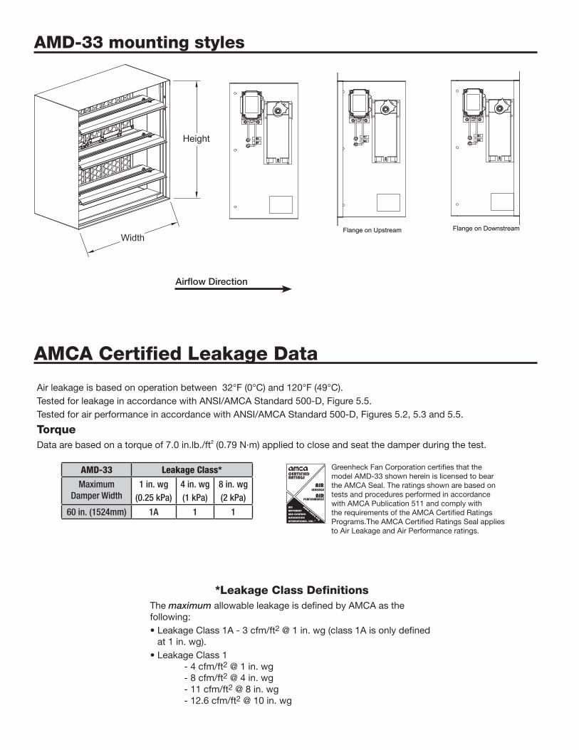
AMD-33 mounting styles
AMCA Certified Leakage Data
Air leakage is based on operation between 32°F (0°C) and 120°F (49°C).Tested for leakage in accordance with ANSI/AMCA Standard 500-D, Figure 5.5.Tested for air performance in accordance with ANSI/AMCA Standard 500-D, Figures 5.2, 5.3 and 5.5.
TorqueData are based on a torque of 7.0 in.lb./ft² (0.79 N·m) applied to close and seat the damper during the test.
AMD-33 Leakage Class*
Maximum Damper Width
1 in. wg (0.25 kPa)
4 in. wg(1 kPa)
8 in. wg(2 kPa)
60 in. (1524mm) 1A 1 1
*Leakage Class DefinitionsThe maximum allowable leakage is defined by AMCA as the following:• Leakage Class 1A - 3 cfm/ft2 @ 1 in. wg (class 1A is only defined
at 1 in. wg).• Leakage Class 1 - 4 cfm/ft2 @ 1 in. wg - 8 cfm/ft2 @ 4 in. wg - 11 cfm/ft2 @ 8 in. wg - 12.6 cfm/ft2 @ 10 in. wg
Airflow Direction
Flange on Upstream Flange on DownstreamFlange on Upstream Flange on DownstreamFlange on Upstream Flange on Downstream
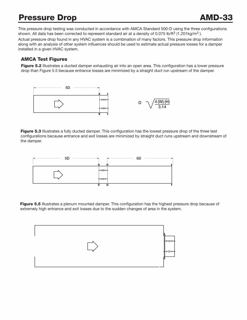
AMCA Test FiguresFigure 5.2 Illustrates a ducted damper exhausting air into an open area. This configuration has a lower pressure drop than Figure 5.5 because entrance losses are minimized by a straight duct run upstream of the damper.
Figure 5.3 Illustrates a fully ducted damper. This configuration has the lowest pressure drop of the three test configurations because entrance and exit losses are minimized by straight duct runs upstream and downstream of the damper.
Figure 5.5 Illustrates a plenum mounted damper. This configuration has the highest pressure drop because of extremely high entrance and exit losses due to the sudden changes of area in the system.
5D 6D
5D
D 4 (W) (H)3.14
5D 6D
5D
D 4 (W) (H)3.14
5D 6D
5D
D 4 (W) (H)3.14
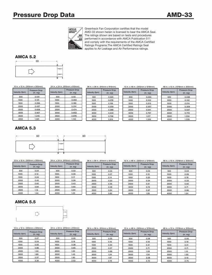
Pressure Drop AMD-33This pressure drop testing was conducted in accordance with AMCA Standard 500-D using the three configurations shown. All data has been corrected to represent standard air at a density of 0.075 lb/ft3 (1.201kg/m3 ).Actual pressure drop found in any HVAC system is a combination of many factors. This pressure drop information along with an analysis of other system influences should be used to estimate actual pressure losses for a damper installed in a given HVAC system.
Greenheck Fan Corporation certifies that the model AMD-33 shown herein is licensed to bear the AMCA Seal. The ratings shown are based on tests and procedures performed in accordance with AMCA Publication 511 and comply with the requirements of the AMCA Certified Ratings Programs.The AMCA Certified Ratings Seal applies to Air Leakage and Air Performance ratings.
Pressure Drop Data AMD-33
5D 6D
5D
D 4 (W) (H)3.14
5D 6D
5D
D 4 (W) (H)3.14
AMCA 5.2
AMCA 5.3
AMCA 5.5
5D 6D
5D
D 4 (W) (H)3.14
Velocity (fpm)Pressure Drop
(in. wg) Velocity (fpm)Pressure Drop
(in. wg) Velocity (fpm)Pressure Drop
(in. wg)
500 0.041 500 0.03 500 0.025
1000 0.131 1000 0.094 1000 0.078
1500 0.266 1500 0.189 1500 0.156
2000 0.437 2000 0.314 2000 0.259
2500 0.658 2500 0.474 2500 0.388
3000 0.927 3000 0.652 3000 0.533
3500 1.245 3500 0.876 3500 0.706
4000 1.591 4000 1.143 4000 0.914
12 in. x 12 in. (305mm x 305mm) 24 in. x 24 in. (610mm x 610mm) 36 in. x 36 in. (914mm x 914mm)
Velocity (fpm)Pressure Drop
(in. wg)
500 0.036
1000 0.102
1500 0.214
2000 0.359
2500 0.547
3000 0.772
3500 1.034
4000 1.339
48 in. x 12 in. (1219mm x 305mm)
Velocity (fpm)Pressure Drop
(in. wg)
500 0.034
1000 0.103
1500 0.213
2000 0.357
2500 0.541
3000 0.757
3500 1.017
4000 1.326
12 in. x 48 in. (305mm x 1219mm)
Velocity (fpm)Pressure Drop
(in. wg) Velocity (fpm)Pressure Drop
(in. wg) Velocity (fpm)Pressure Drop
(in. wg)
500 0.04 500 0.03 500 0.03
1000 0.12 1000 0.09 1000 0.07
1500 0.24 1500 0.17 1500 0.14
2000 0.40 2000 0.28 2000 0.23
2500 0.60 2500 0.43 2500 0.35
3000 0.84 3000 0.60 3000 0.48
3500 1.12 3500 0.80 3500 0.64
4000 1.44 4000 1.03 4000 0.82
12 in. x 12 in. (305mm x 305mm) 24 in. x 24 in. (610mm x 610mm) 36 in. x 36 in. (914mm x 914mm)
Velocity (fpm)Pressure Drop
(in. wg)
500 0.03
1000 0.09
1500 0.19
2000 0.33
2500 0.50
3000 0.71
3500 0.96
4000 1.24
48 in. x 12 in. (1219mm x 305mm)
Velocity (fpm)Pressure Drop
(in. wg)
500 0.03
1000 0.10
1500 0.20
2000 0.34
2500 0.51
3000 0.72
3500 0.97
4000 1.26
12 in. x 48 in. (305mm x 1219mm)
Velocity (fpm)Pressure Drop
(in. wg) Velocity (fpm)Pressure Drop
(in. wg) Velocity (fpm)Pressure Drop
(in. wg)
500 0.07 500 0.05 500 0.05
1000 0.24 1000 0.19 1000 0.16
1500 0.50 1500 0.38 1500 0.34
2000 0.86 2000 0.65 2000 0.57
2500 1.33 2500 1.00 2500 0.88
3000 1.89 3000 1.43 3000 1.24
3500 2.57 3500 1.90 3500 1.67
4000 3.30 4000 2.52 4000 2.19
12 in. x 12 in. (305mm x 305mm) 24 in. x 24 in. (610mm x 610mm) 36 in. x 36 in. (914mm x 914mm)
Velocity (fpm)Pressure Drop
(in. wg)
500 0.05
1000 0.19
1500 0.41
2000 0.71
2500 1.10
3000 1.55
3500 2.10
4000 2.75
48 in. x 12 in. (1219mm x 305mm)
Velocity (fpm)Pressure Drop
(in. wg)
500 0.06
1000 0.19
1500 0.41
2000 0.71
2500 1.09
3000 1.54
3500 2.08
4000 2.70
12 in. x 48 in. (305mm x 1219mm)
Copyright © 2017 Greenheck Fan Corporation
AMD-33 Rev. 9 February 2017
SpecificationsControl dampers meeting the following specifications shall be installed where shown on plans as an air monitor.station integral to the minimum outside air damper. The air measuring damper shall control the minimum amount of outside air as recommended by ASHRAE Standard 62 or California Title 24.The air measuring damper shall consist of: 16 ga. (1.5mm) galvanized steel hat channel frame with 5 in. (127mm) depth; airfoil shaped, galvanized steel double skin construction blades (14 ga. [2mm] equivalent thickness); blades shall be completely symmetrical relative to their axle pivot point, presenting identical
resistance to airflow in either direction or pressure on either side of the damper. Axles shall be 1/2 in. (13mm) dia. plated steel turning in acetal bearings; TPE blade seals for 250°F (121°C) maximum temperature; flexible stainless steel jamb seals; and external (out of the airstream) blade-to-blade linkage.Damper leakage rating to be in compliance with the IECC (International Energy Conservation Code) and not to exceed 3 cfm/ft2 (55 cmh/m2) at 1 in. wg (0.25 kPa). Testing and ratings to be in accordance with AMCA standard 500-D.Basis of design is Greenheck model AMD-33.
Factory Supplied ControlsBy adding a factory supplied controller AMD series airflow measuring dampers become a turn-key solution for measuring and controlling the flow of air. Go to www.greenheck.com for complete instructions on these two controllers.
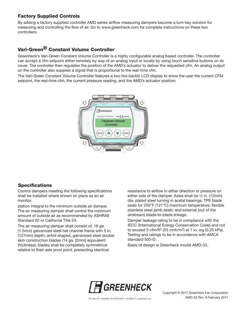
Vari-Green® Constant Volume ControllerGreenheck’s Vari-Green Constant Volume Controller is a highly configurable analog based controller. The controller can accept a cfm setpoint either remotely by way of an analog input or locally by using touch sensitive buttons on its cover. The controller then regulates the position of the AMD’s actuator to deliver the requested cfm. An analog output on the controller also supplies a signal that is proportional to the real-time cfm.The Vari-Green Constant Volume Controller features a two line backlit LCD display to show the user the current CFM setpoint, the real-time cfm, the current pressure reading, and the AMD’s actuator position.
Constant Volume
Varigreen Damper Controller