Embed Size (px)
Citation preview
Version 1.4 ©Copyright 2017, Ambient LLC. All Rights Reserved. Page 1
Ambient Weather WS-14 Wireless 8-Channel Floating Pool
and Spa Thermometer with Daily Min/Max Display User
Manual
Table of Contents
1 Introduction ..................................................................................................................................... 2 2 Getting Started ................................................................................................................................ 2
2.1 Parts List ....................................................................................................................................... 2 2.2 Floating Pool and Spa Thermometer Sensor Set Up ..................................................................... 2 2.3 Sensor Placement .......................................................................................................................... 9
3 Maintenance .................................................................................................................................. 10 4 Display Console Set Up ................................................................................................................ 10
4.1 Display Console Layout ................................................................................................... 11 4.2 Sensor Operation Verification ................................................................................................. 11
5 Display Features ............................................................................................................................ 11 5.1 Console Operation........................................................................................................................... 11
5.1.1 Set Mode .................................................................................................................................. 11 5.1.2 Viewing the High and Low Alarms ...................................................................................... 12 5.1.3 Alarm Defaults ..................................................................................................................... 12 5.1.4 Setting the Min and Max Alarm ....................................................................................... 12
5.2 Manually Reset Max/Min ........................................................................................................... 13 5.3 Channel Selection ....................................................................................................................... 13 5.4 Sensor Search Mode .................................................................................................................... 13 5.5 Best Practices for Wireless Communication ............................................................................... 13 5.6 Adjustment or Calibration ........................................................................................................... 13
5.6.1 Remote Sensor Temperature Calibration.............................................................................. 14 5.6.2 Indoor Temperature Calibration ........................................................................................... 14
6 Glossary of Terms ......................................................................................................................... 15 7 Specifications ................................................................................................................................ 15
7.1 Wireless Specifications ............................................................................................................... 15 7.2 Measurement Specifications ....................................................................................................... 15 7.3 Power Consumption .................................................................................................................... 15
8 Troubleshooting Guide .................................................................................................................. 15 9 Accessories ................................................................................................................................... 17 10 Liability Disclaimer .................................................................................................................. 17 11 FCC Statement .......................................................................................................................... 17 12 Warranty Information ............................................................................................................... 18
Version 1.4 ©Copyright 2017, Ambient LLC. All Rights Reserved. Page 2
1 Introduction Thank you for your purchase of the Ambient Weather WS-14 Wireless 8-Channel Floating Pool and
Spa Thermometer with Daily Min/Max Display. The following user guide provides step by step
instructions for installation, operation and troubleshooting. To download the latest manual and
additional troubleshooting tips, please visit the FAQ website:
http://ambientweather.wikispaces.com/ws14
2 Getting Started
Note: The power up sequence must be performed in the order shown in this section (insert
batteries in the remote transmitter(s) first, Display Console second).
The WS-14 weather station consists of a display console (receiver), and a thermometer (remote
transmitter).
2.1 Parts List QTY Item
1 Thermometer transmitter (F007PF) for pool/spa
Dimensions (LxHxW): 8.5” x 4.2” x 3.7” (216 x 106 x 95mm)
LCD Dimensions (LxW): 1.1 x 0.62” (27 x 16mm)
Remote sensor depth: 7.1’’ (180mm)
1
Display Console
Frame Dimensions (LxHxW): 4.0 x 2.95 x 1.00 in
LCD Dimensions (LxW): 1.96 x 1.77”
LCD Segment Height: 0.78 inches
1 User Manual
2.2 Floating Pool and Spa Thermometer Sensor Set Up
Note: We recommend fresh alkaline batteries for temperature ranges between -4 °F and 140 °F
and fresh lithium batteries for temperature ranges between -40 °F and 140 °F. The solar panel does not
charge the batteries, so rechargeable batteries are not needed or recommended.
Version 1.4 ©Copyright 2017, Ambient LLC. All Rights Reserved. Page 3
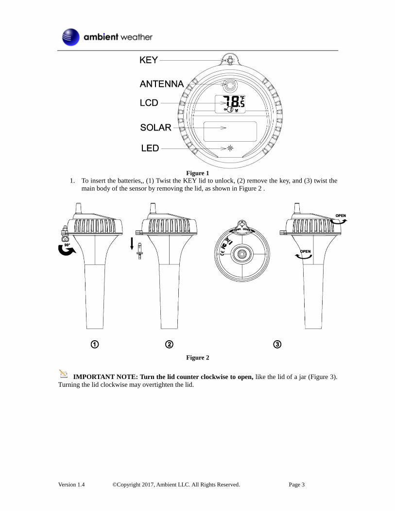
Figure 1
1. To insert the batteries,, (1) Twist the KEY lid to unlock, (2) remove the key, and (3) twist the
main body of the sensor by removing the lid, as shown in Figure 2 .
Figure 2
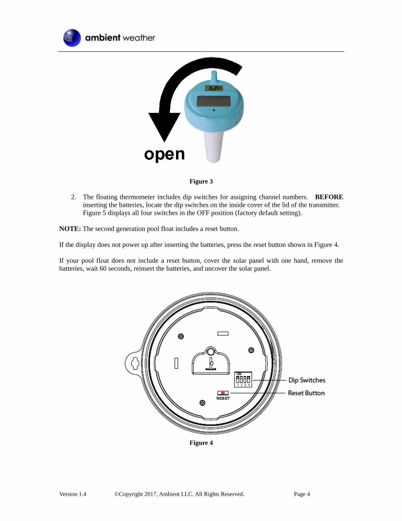
IMPORTANT NOTE: Turn the lid counter clockwise to open, like the lid of a jar (Figure 3).
Turning the lid clockwise may overtighten the lid.
Version 1.4 ©Copyright 2017, Ambient LLC. All Rights Reserved. Page 4
Figure 3
2. The floating thermometer includes dip switches for assigning channel numbers. BEFORE
inserting the batteries, locate the dip switches on the inside cover of the lid of the transmitter.
Figure 5 displays all four switches in the OFF position (factory default setting).
NOTE: The second generation pool float includes a reset button.
If the display does not power up after inserting the batteries, press the reset button shown in Figure 4.
If your pool float does not include a reset button, cover the solar panel with one hand, remove the
batteries, wait 60 seconds, reinsert the batteries, and uncover the solar panel.
Figure 4
Version 1.4 ©Copyright 2017, Ambient LLC. All Rights Reserved. Page 5
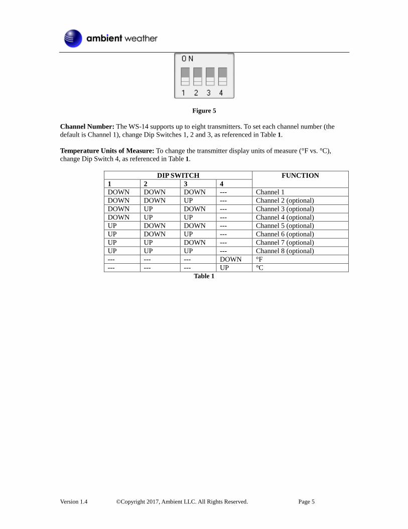
Figure 5
Channel Number: The WS-14 supports up to eight transmitters. To set each channel number (the
default is Channel 1), change Dip Switches 1, 2 and 3, as referenced in Table 1.
Temperature Units of Measure: To change the transmitter display units of measure (°F vs. °C),
change Dip Switch 4, as referenced in Table 1.
DIP SWITCH FUNCTION
1 2 3 4
DOWN DOWN DOWN --- Channel 1
DOWN DOWN UP --- Channel 2 (optional)
DOWN UP DOWN --- Channel 3 (optional)
DOWN UP UP --- Channel 4 (optional)
UP DOWN DOWN --- Channel 5 (optional)
UP DOWN UP --- Channel 6 (optional)
UP UP DOWN --- Channel 7 (optional)
UP UP UP --- Channel 8 (optional)
--- --- --- DOWN °F
--- --- --- UP °C
Table 1
Version 1.4 ©Copyright 2017, Ambient LLC. All Rights Reserved. Page 6
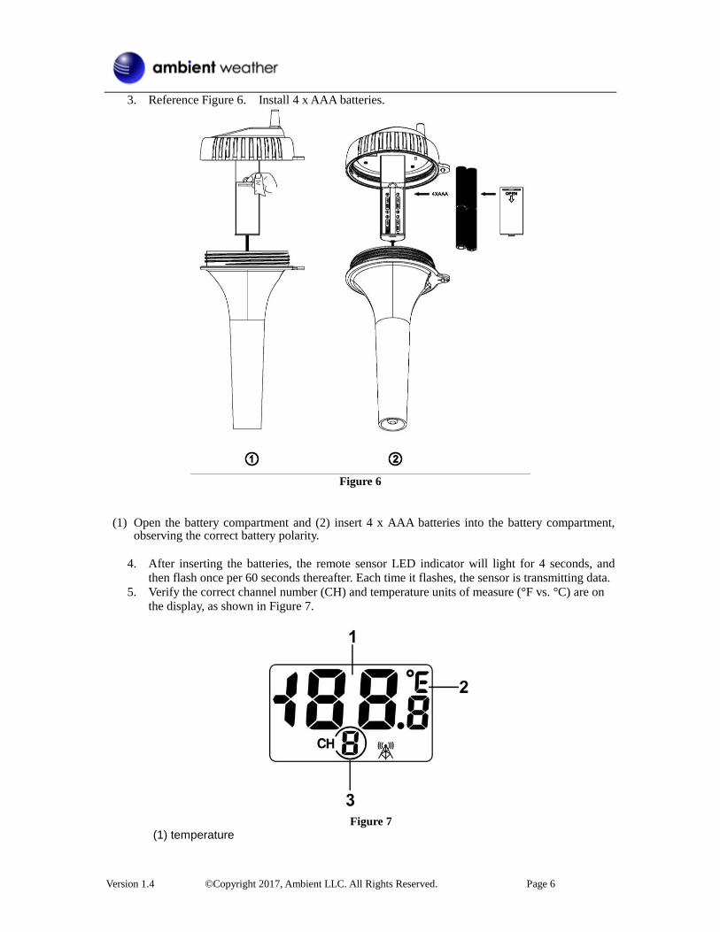
3. Reference Figure 6. Install 4 x AAA batteries.
Figure 6
(1) Open the battery compartment and (2) insert 4 x AAA batteries into the battery compartment,
observing the correct battery polarity.
4. After inserting the batteries, the remote sensor LED indicator will light for 4 seconds, and
then flash once per 60 seconds thereafter. Each time it flashes, the sensor is transmitting data.
5. Verify the correct channel number (CH) and temperature units of measure (°F vs. °C) are on
the display, as shown in Figure 7.
Figure 7
(1) temperature
Version 1.4 ©Copyright 2017, Ambient LLC. All Rights Reserved. Page 7
(2) temperature units (°F vs. °C) (3) channel number
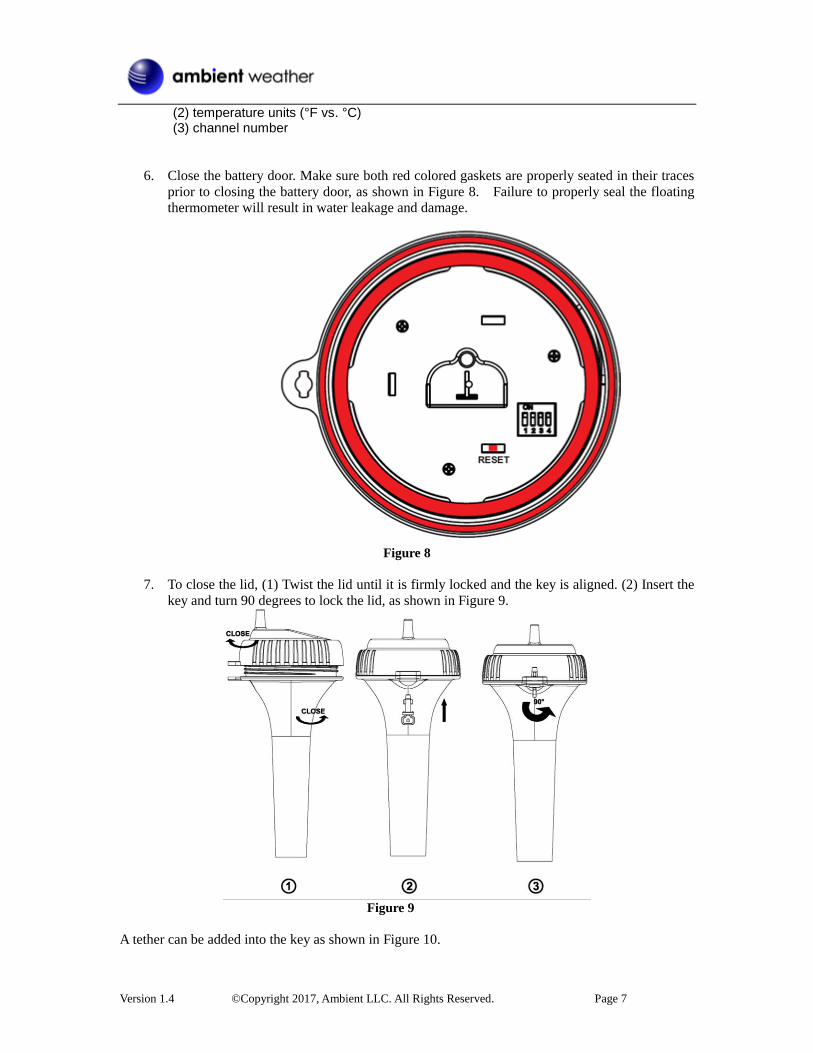
6. Close the battery door. Make sure both red colored gaskets are properly seated in their traces
prior to closing the battery door, as shown in Figure 8. Failure to properly seal the floating
thermometer will result in water leakage and damage.
Figure 8
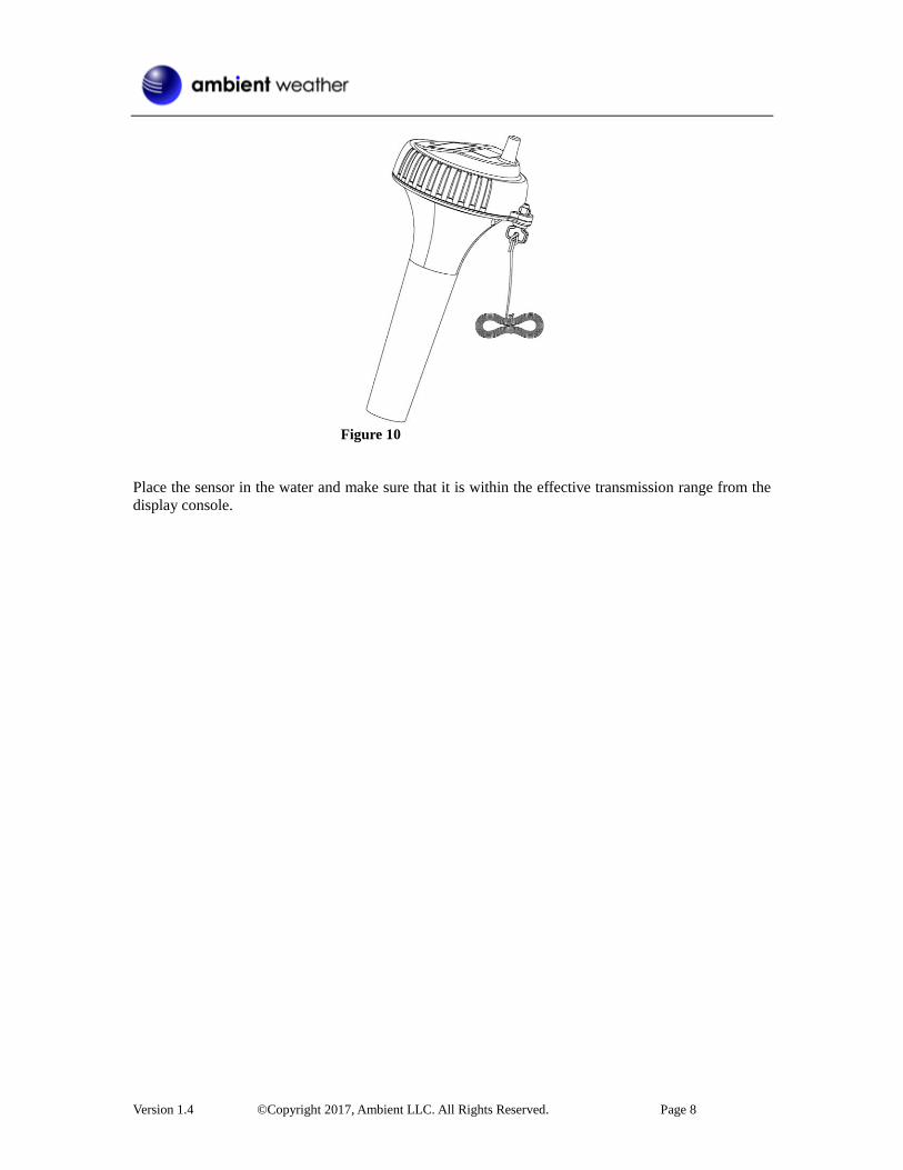
7. To close the lid, (1) Twist the lid until it is firmly locked and the key is aligned. (2) Insert the
key and turn 90 degrees to lock the lid, as shown in Figure 9.
Figure 9
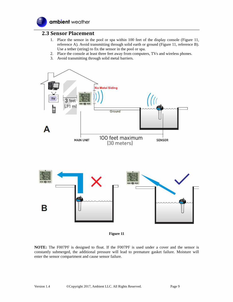
A tether can be added into the key as shown in Figure 10.
Version 1.4 ©Copyright 2017, Ambient LLC. All Rights Reserved. Page 8
Figure 10
Place the sensor in the water and make sure that it is within the effective transmission range from the
display console.
Version 1.4 ©Copyright 2017, Ambient LLC. All Rights Reserved. Page 9
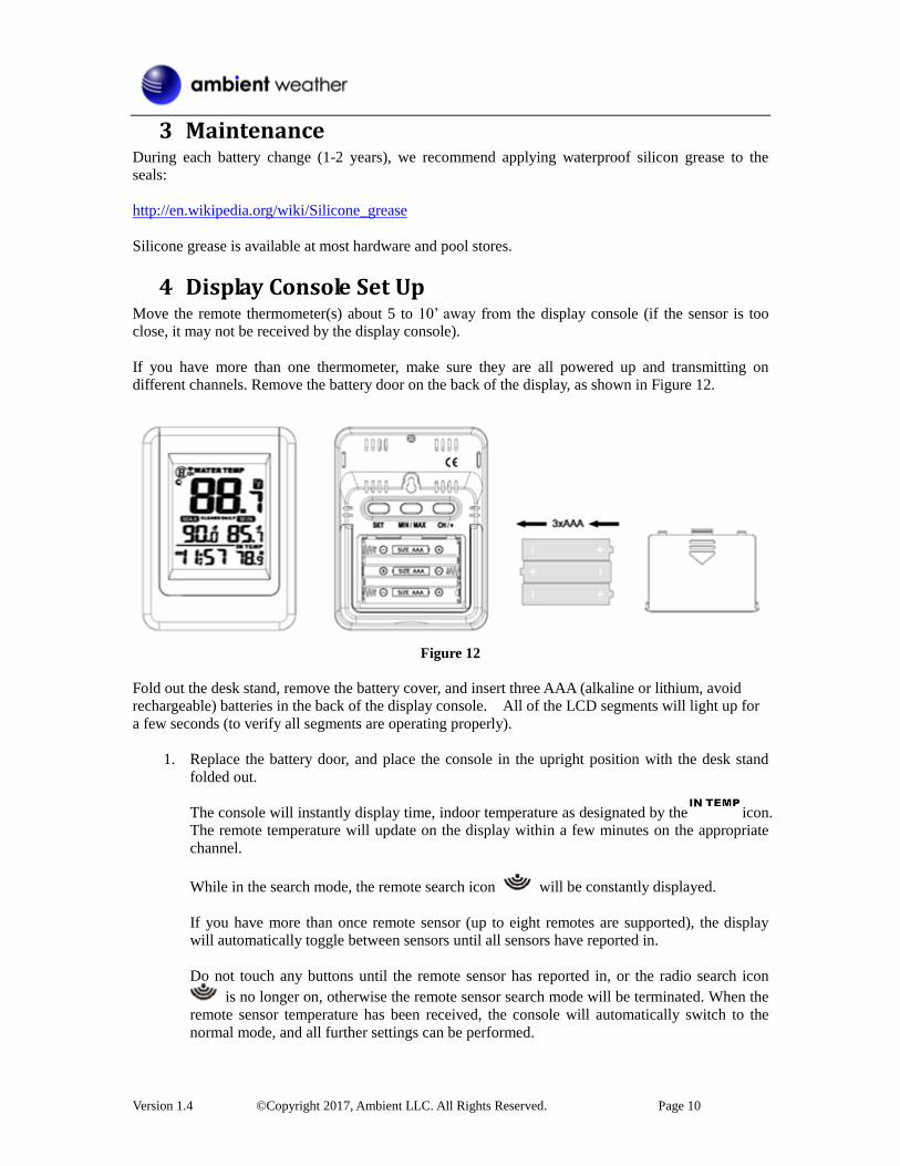
2.3 Sensor Placement 1. Place the sensor in the pool or spa within 100 feet of the display console (Figure 11,
reference A). Avoid transmitting through solid earth or ground (Figure 11, reference B).
Use a tether (string) to fix the sensor in the pool or spa.
2. Place the console at least three feet away from computers, TVs and wireless phones.
3. Avoid transmitting through solid metal barriers.
Figure 11
NOTE: The F007PF is designed to float. If the F007PF is used under a cover and the sensor is
constantly submerged, the additional pressure will lead to premature gasket failure. Moisture will
enter the sensor compartment and cause sensor failure.
Version 1.4 ©Copyright 2017, Ambient LLC. All Rights Reserved. Page 10
3 Maintenance During each battery change (1-2 years), we recommend applying waterproof silicon grease to the
seals:
http://en.wikipedia.org/wiki/Silicone_grease
Silicone grease is available at most hardware and pool stores.
4 Display Console Set Up Move the remote thermometer(s) about 5 to 10’ away from the display console (if the sensor is too
close, it may not be received by the display console).
If you have more than one thermometer, make sure they are all powered up and transmitting on
different channels. Remove the battery door on the back of the display, as shown in Figure 12.
Figure 12
Fold out the desk stand, remove the battery cover, and insert three AAA (alkaline or lithium, avoid
rechargeable) batteries in the back of the display console. All of the LCD segments will light up for
a few seconds (to verify all segments are operating properly).
1. Replace the battery door, and place the console in the upright position with the desk stand
folded out.
The console will instantly display time, indoor temperature as designated by the icon.
The remote temperature will update on the display within a few minutes on the appropriate
channel.
While in the search mode, the remote search icon will be constantly displayed.
If you have more than once remote sensor (up to eight remotes are supported), the display
will automatically toggle between sensors until all sensors have reported in.
Do not touch any buttons until the remote sensor has reported in, or the radio search icon
is no longer on, otherwise the remote sensor search mode will be terminated. When the
remote sensor temperature has been received, the console will automatically switch to the
normal mode, and all further settings can be performed.
Version 1.4 ©Copyright 2017, Ambient LLC. All Rights Reserved. Page 11
If the remote does not update, please reference the troubleshooting guide in Section 8.
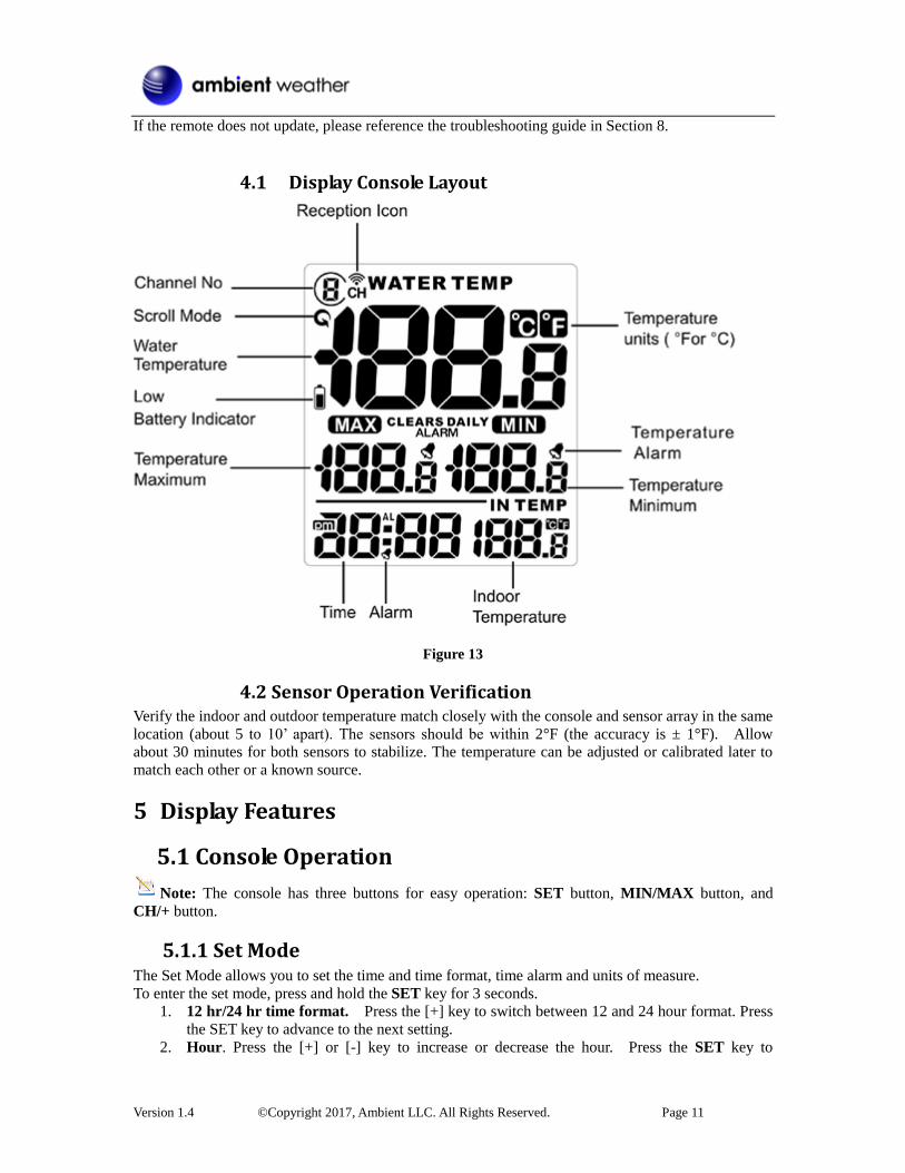
4.1 Display Console Layout
Figure 13
4.2 Sensor Operation Verification Verify the indoor and outdoor temperature match closely with the console and sensor array in the same
location (about 5 to 10’ apart). The sensors should be within 2°F (the accuracy is ± 1°F). Allow
about 30 minutes for both sensors to stabilize. The temperature can be adjusted or calibrated later to
match each other or a known source.
5 Display Features
5.1 Console Operation
Note: The console has three buttons for easy operation: SET button, MIN/MAX button, and
CH/+ button.
5.1.1 Set Mode The Set Mode allows you to set the time and time format, time alarm and units of measure.
To enter the set mode, press and hold the SET key for 3 seconds.
1. 12 hr/24 hr time format. Press the [+] key to switch between 12 and 24 hour format. Press
the SET key to advance to the next setting.
2. Hour. Press the [+] or [-] key to increase or decrease the hour. Press the SET key to
Version 1.4 ©Copyright 2017, Ambient LLC. All Rights Reserved. Page 12
advance to the next setting.
3. Minute. Press the [+] or [-] key to increase or decrease the minute. Press the SET key to
advance to the next setting.
4. Alarm Hour. Press the [+] or [-] key to increase or decrease the alarm hour. While the alarm
value is flashing, press and hold the SET button for three seconds to toggle the alarm on and
off the alarm. The time alarm icon will appear when set, and disappear when disabled.
Press (do not hold) the SET key to advance to the next setting.
5. Alarm Minute. Press the [+] or [-] key to increase or decrease the alarm minute. While the
alarm value is flashing, press and hold the SET button for three seconds to toggle the alarm
on and off the alarm. The time alarm icon will appear when set, and disappear when
disabled. Press(do not hold) the SET key to advance to the next setting.
6. Temperature Units of Measure. Press the [+] key to switch between °F and °C units of
measure. Press the SET key to advance to the next setting.
7. Max/Min Clearing. The Max/Min can be programmed to clear daily (at midnight) or
manually. Press the [+] key to switch between “Clears Daily” and Clears Manually. Press
the SET key to exit setting.
5.1.2 Viewing the High and Low Alarms The high and low alarms can be set for Channels 1 and 2 only. Press the CH/+ button to switch the
display between Channel 1 and 2.
Next, press the SET button to view the High (MAX) and LOW (MIN) alarm along with the alarm
time. Press the SET button again to return to the normal mode.
5.1.3 Alarm Defaults
Channel Default Condition HI ALARM (temperature) ºF LOW ALARM (temperature)ºF
1 OFF 100 60
2 OFF 110 90
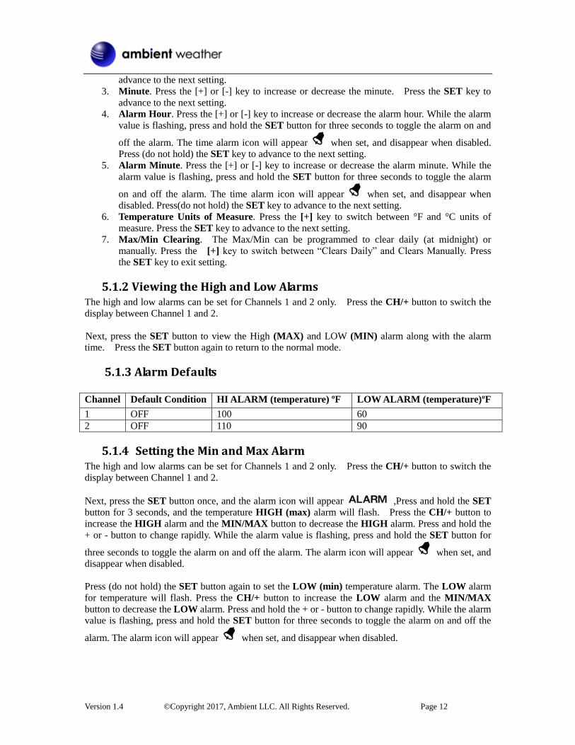
5.1.4 Setting the Min and Max Alarm The high and low alarms can be set for Channels 1 and 2 only. Press the CH/+ button to switch the
display between Channel 1 and 2.
Next, press the SET button once, and the alarm icon will appear ,Press and hold the SET
button for 3 seconds, and the temperature HIGH (max) alarm will flash. Press the CH/+ button to
increase the HIGH alarm and the MIN/MAX button to decrease the HIGH alarm. Press and hold the
+ or - button to change rapidly. While the alarm value is flashing, press and hold the SET button for
three seconds to toggle the alarm on and off the alarm. The alarm icon will appear when set, and
disappear when disabled.
Press (do not hold) the SET button again to set the LOW (min) temperature alarm. The LOW alarm
for temperature will flash. Press the CH/+ button to increase the LOW alarm and the MIN/MAX
button to decrease the LOW alarm. Press and hold the + or - button to change rapidly. While the alarm
value is flashing, press and hold the SET button for three seconds to toggle the alarm on and off the
alarm. The alarm icon will appear when set, and disappear when disabled.
Version 1.4 ©Copyright 2017, Ambient LLC. All Rights Reserved. Page 13
5.2 Manually Reset Max/Min In normal mode , Press the MIN/MAX button once to view the MAX values. Press the MIN/MAX
button again to view the MIN values.
Press the MIN/MAX button again to return to normal mode.
To reset the Max/Min values, press and hold the MIN/MAX- button for 3 seconds.
5.3 Channel Selection Press the CH/+ button to switch the display between remote sensors 1 through 8, and scroll mode
. In scroll mode, all of detected outdoor sensors will be displayed in five second intervals.
5.4 Sensor Search Mode If any of the sensor communication is lost, dashes (--.-) will be displayed on the screen. To reacquire
the signal:
1. If a specific channel is lost, press the CH/+ button to display this channel, then Press and hold
the CH/+ button for 3 seconds, and the remote search icon will be constantly displayed
for up to 3 minutes. Once the signal is reacquired, the remote search icon will turn off,
and the current values will be displayed.
2. If new sensors are added, subtracted, or multiple sensor channels are lost, Press and hold the
CH/+ button for 5 seconds (on any channel), and the remote search icon will be
constantly displayed for up to 10 minutes. Once the signal is reacquired, the remote search
icon will turn off, and the current values will be displayed.
5.5 Best Practices for Wireless Communication Wireless communication is susceptible to interference, distance, walls and metal barriers. We
recommend the following best practices for trouble free wireless communication.
1. Electro-Magnetic Interference (EMI). Keep the console several feet away from computer
monitors and TVs.
2. Radio Frequency Interference (RFI). If you have other 433 MHz devices and
communication is intermittent, try turning off these other devices for troubleshooting
purposes. You may need to relocate the transmitters or receivers to avoid intermittent
communication.
3. Line of Sight Rating. This device is rated at 150 feet line of sight (no interference, barriers or
walls) but typically you will get 100 feet maximum under most real-world installations,
which include passing through barriers or walls.
4. Metal Barriers. Radio frequency will not pass through metal barriers such as aluminum
siding. If you have metal siding, align the remote and console through a window to get a clear
line of sight.
5.6 Adjustment or Calibration
Note: The calibrated value can only be adjusted on the console. The remote sensor(s) always
displays the un-calibrated or measured value.
The purpose of calibration is to fine tune or correct for any sensor error associated with the devices
margin of error. The measurement can be adjusted from the console to calibrate to a known source.
Calibration is only useful if you have a known calibrated source you can compare it against, and is
Version 1.4 ©Copyright 2017, Ambient LLC. All Rights Reserved. Page 14
optional. This section discusses practices, procedures and sources for sensor calibration to reduce
manufacturing and degradation errors. Do not compare your readings obtained from sources such as
the internet, radio, television or newspapers. They are in a different location and typically update once
per hour.
The purpose of your weather station is to measure conditions of your surroundings, which vary
significantly from location to location.
5.6.1 Remote Sensor Temperature Calibration Prior to entering the calibration mode, press the CH/+ button to select the remote temperature sensor
you wish to adjust.
To enter the temperature calibration mode, press and hold the SET and CH/+ buttons at the same
time for 5 seconds and the remote temperature value will begin flashing. Press the CH/+ button to
increase the temperature and the MIN/MAX button to decrease the temperature reading in 0.1°
increments. To rapidly increase (or decrease) the temperature reading, press and hold the CH/+ or
MIN/MAX button.
To return the temperature to the actual or uncalibrated measurement, press the SET button.
Once the displayed temperature equals the calibrated source, press and hold the SET button for three
seconds, or wait 15 seconds for timeout, and the temperature value will stop flashing.
5.6.2 Indoor Temperature Calibration To enter the indoor temperature calibration mode, press and hold the SET and MIN/MAX buttons at
the same time for 5 seconds and the IN-TEMP temperature value will begin flashing. Press the CH/+
button to increase the temperature and the MIN/MAX button to decrease the temperature reading in
0.1° increments. To rapidly increase (or decrease) the temperature reading, press and hold the CH/+ or
MIN/MAX button.
To return the temperature to the actual or uncalibrated measurement, press the SET button.
Once the displayed temperature equals the calibrated source, press and hold the SET button for three
seconds, or wait 15 seconds for timeout, and the temperature value will stop flashing.
Discussion: Temperature errors can occur when a sensor is placed too close to a heat source (such
as a building structure, the ground or trees).
To calibrate temperature, we recommend a mercury or red spirit (fluid) thermometer. Bi-metal (dial)
and other digital thermometers are not a good source and have their own margin of error. Using a local
weather station in your area is also a poor source due to changes in location, timing (airport weather
stations are only updated once per hour) and possible calibration errors (many official weather stations
are not properly installed and calibrated).
Place the sensor in a shaded, controlled environment next to the fluid thermometer, and allow the
sensor to stabilize for 48 hours. Compare this temperature to the fluid thermometer and adjust the
console to match the fluid thermometer.
Version 1.4 ©Copyright 2017, Ambient LLC. All Rights Reserved. Page 15
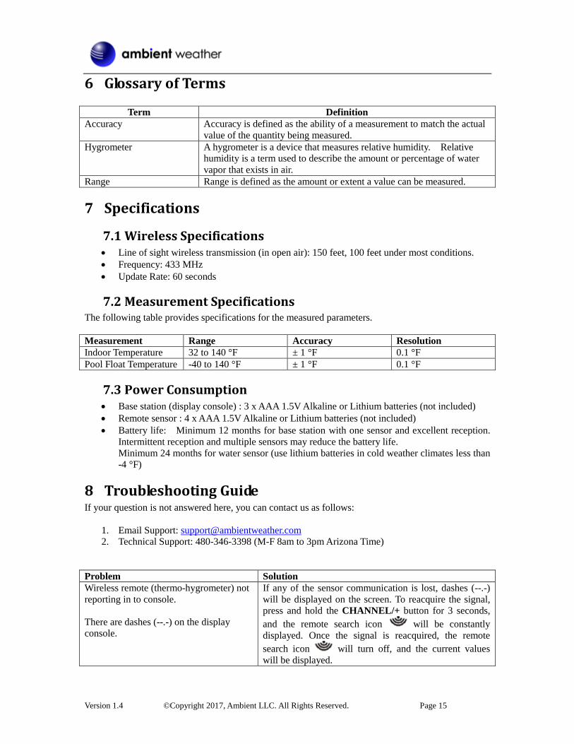
6 Glossary of Terms
Term Definition
Accuracy Accuracy is defined as the ability of a measurement to match the actual
value of the quantity being measured.
Hygrometer A hygrometer is a device that measures relative humidity. Relative
humidity is a term used to describe the amount or percentage of water
vapor that exists in air.
Range Range is defined as the amount or extent a value can be measured.
7 Specifications
7.1 Wireless Specifications Line of sight wireless transmission (in open air): 150 feet, 100 feet under most conditions.
Frequency: 433 MHz
Update Rate: 60 seconds
7.2 Measurement Specifications The following table provides specifications for the measured parameters.
Measurement Range Accuracy Resolution
Indoor Temperature 32 to 140 °F ± 1 °F 0.1 °F
Pool Float Temperature -40 to 140 °F ± 1 °F 0.1 °F
7.3 Power Consumption Base station (display console) : 3 x AAA 1.5V Alkaline or Lithium batteries (not included)
Remote sensor : 4 x AAA 1.5V Alkaline or Lithium batteries (not included)
Battery life: Minimum 12 months for base station with one sensor and excellent reception.
Intermittent reception and multiple sensors may reduce the battery life.
Minimum 24 months for water sensor (use lithium batteries in cold weather climates less than
-4 °F)
8 Troubleshooting Guide If your question is not answered here, you can contact us as follows:
1. Email Support: [email protected]
2. Technical Support: 480-346-3398 (M-F 8am to 3pm Arizona Time)
Problem Solution
Wireless remote (thermo-hygrometer) not
reporting in to console.
There are dashes (--.-) on the display
console.
If any of the sensor communication is lost, dashes (--.-)
will be displayed on the screen. To reacquire the signal,
press and hold the CHANNEL/+ button for 3 seconds,
and the remote search icon will be constantly
displayed. Once the signal is reacquired, the remote
search icon will turn off, and the current values
will be displayed.
Version 1.4 ©Copyright 2017, Ambient LLC. All Rights Reserved. Page 16
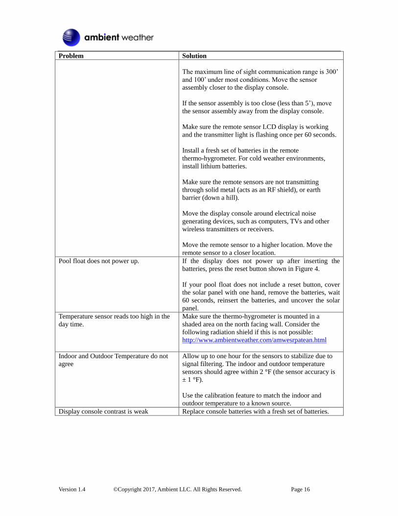
Problem Solution
The maximum line of sight communication range is 300’
and 100’ under most conditions. Move the sensor
assembly closer to the display console.
If the sensor assembly is too close (less than 5’), move
the sensor assembly away from the display console.
Make sure the remote sensor LCD display is working
and the transmitter light is flashing once per 60 seconds.
Install a fresh set of batteries in the remote
thermo-hygrometer. For cold weather environments,
install lithium batteries.
Make sure the remote sensors are not transmitting
through solid metal (acts as an RF shield), or earth
barrier (down a hill).
Move the display console around electrical noise
generating devices, such as computers, TVs and other
wireless transmitters or receivers.
Move the remote sensor to a higher location. Move the
remote sensor to a closer location.
Pool float does not power up. If the display does not power up after inserting the
batteries, press the reset button shown in Figure 4.
If your pool float does not include a reset button, cover
the solar panel with one hand, remove the batteries, wait
60 seconds, reinsert the batteries, and uncover the solar
panel.
Temperature sensor reads too high in the
day time.
Make sure the thermo-hygrometer is mounted in a
shaded area on the north facing wall. Consider the
following radiation shield if this is not possible:
http://www.ambientweather.com/amwesrpatean.html
Indoor and Outdoor Temperature do not
agree
Allow up to one hour for the sensors to stabilize due to
signal filtering. The indoor and outdoor temperature
sensors should agree within 2 °F (the sensor accuracy is
± 1 °F).
Use the calibration feature to match the indoor and
outdoor temperature to a known source.
Display console contrast is weak Replace console batteries with a fresh set of batteries.
Version 1.4 ©Copyright 2017, Ambient LLC. All Rights Reserved. Page 17
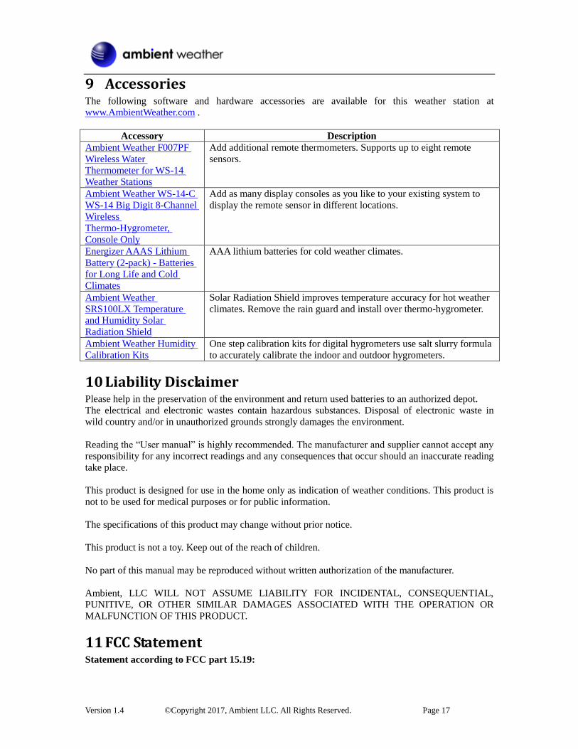
9 Accessories The following software and hardware accessories are available for this weather station at
www.AmbientWeather.com .
Accessory Description
Ambient Weather F007PF
Wireless Water
Thermometer for WS-14
Weather Stations
Add additional remote thermometers. Supports up to eight remote
sensors.
Ambient Weather WS-14-C
WS-14 Big Digit 8-Channel
Wireless
Thermo-Hygrometer,
Console Only
Add as many display consoles as you like to your existing system to
display the remote sensor in different locations.
Energizer AAAS Lithium
Battery (2-pack) - Batteries
for Long Life and Cold
Climates
AAA lithium batteries for cold weather climates.
Ambient Weather
SRS100LX Temperature
and Humidity Solar
Radiation Shield
Solar Radiation Shield improves temperature accuracy for hot weather
climates. Remove the rain guard and install over thermo-hygrometer.
Ambient Weather Humidity
Calibration Kits
One step calibration kits for digital hygrometers use salt slurry formula
to accurately calibrate the indoor and outdoor hygrometers.
10 Liability Disclaimer Please help in the preservation of the environment and return used batteries to an authorized depot.
The electrical and electronic wastes contain hazardous substances. Disposal of electronic waste in
wild country and/or in unauthorized grounds strongly damages the environment.
Reading the “User manual” is highly recommended. The manufacturer and supplier cannot accept any
responsibility for any incorrect readings and any consequences that occur should an inaccurate reading
take place.
This product is designed for use in the home only as indication of weather conditions. This product is
not to be used for medical purposes or for public information.
The specifications of this product may change without prior notice.
This product is not a toy. Keep out of the reach of children.
No part of this manual may be reproduced without written authorization of the manufacturer.
Ambient, LLC WILL NOT ASSUME LIABILITY FOR INCIDENTAL, CONSEQUENTIAL,
PUNITIVE, OR OTHER SIMILAR DAMAGES ASSOCIATED WITH THE OPERATION OR
MALFUNCTION OF THIS PRODUCT.
11 FCC Statement Statement according to FCC part 15.19:
Version 1.4 ©Copyright 2017, Ambient LLC. All Rights Reserved. Page 18
This device complies with part 15 of the FCC rules. Operation is subject to the following two
conditions:
1. This device may not cause harmful interference.
2. This device must accept any interference received, including interference that may cause
undesired operation.
Statement according to FCC part 15.21: Modifications not expressly approved by this company could void the user's authority to operate the
equipment.
Statement according to FCC part 15.105: NOTE: This equipment has been tested and found to comply with the limits for a Class B digital
device, pursuant to Part 15 of the FCC Rules. These limits are designed to provide reasonable
protection against harmful interference in a residential installation. This equipment generates, uses and
can radiate radio frequency energy and, if not installed and used in accordance with the instructions,
may cause harmful interference to radio communications.
However, there is no guarantee that interference will not occur in a particular installation. If this
equipment does cause harmful interference to radio or television reception, which can be determined
by turning the equipment off and on, the user is encouraged to try to correct the interference by one or
more of the following measures:
• Reorient or relocate the receiving antenna.
• Increase the separation between the equipment and receiver.
• Connect the equipment into an outlet on a circuit different from that to which the receiver is
connected.
• Consult the dealer or an experienced radio/TV technician for help.
12 Warranty Information Ambient, LLC provides a 1-year limited warranty on this product against manufacturing defects in
materials and workmanship.
This limited warranty begins on the original date of purchase, is valid only on products purchased and
only to the original purchaser of this product. To receive warranty service, the purchaser must contact
Ambient, LLC for problem determination and service procedures.
Warranty service can only be performed by a Ambient, LLC. The original dated bill of sale must be
presented upon request as proof of purchase to Ambient, LLC.
Your Ambient, LLC warranty covers all defects in material and workmanship with the following
specified exceptions: (1) damage caused by accident, unreasonable use or neglect (lack of reasonable
and necessary maintenance); (2) damage resulting from failure to follow instructions contained in your
owner’s manual; (3) damage resulting from the performance of repairs or alterations by someone other
than an authorized Ambient, LLC authorized service center; (4) units used for other than home use (5)
applications and uses that this product was not intended (6) the products inability to receive a signal
due to any source of interference or metal obstructions and (7) extreme acts of nature, such as
lightning strikes or floods.
This warranty covers only actual defects within the product itself, and does not cover the cost of
installation or removal from a fixed installation, normal set-up or adjustments, claims based on
misrepresentation by the seller or performance variations resulting from installation-related
circumstances.

Version 1.4 ©Copyright 2017, Ambient LLC. All Rights Reserved. Page 19