Embed Size (px)
Citation preview
Ambient Solution,Advanced Technology
Printing Date : September 11
RO
TARY
com
pre
ssor
Website : www.siamcompressor.com
Siam Compressor Industry Co., Ltd.
Head Office & Factory : Laem Chabang Industrial Estate 87/10 Moo 2, Sukhumvit Road, Sriracha, Chonburi 20230, Thailand
Tel. +66 (0) 38 490 900 to 912 Fax. +66 (0) 38 490 917
Marketing Office : 979/108 - 110, 32nd Floor S.M. Tower Phaholyothin Road, Samsennai, Phayathai, Bangkok 10400, Thailand
Tel. +66 (0) 2298 0371 to 377 Fax. +66 (0) 2298 0411 to 412

23
Operation Standards and Limits ofR-410A Compressor TNB, SNB Model Contents
Condition Application : Application Range ASRE - T Rating Condition
• Evaporating Temperature Range -27˚C to 26˚C (-16.6˚F to 78.8˚F) • Evaporating Temperature 7.2˚C (45˚F) • Condensing Temperature Range -27˚C to 65˚C (-16.6˚F to 149˚F) • Return Gas Temperature 35.0˚C (95˚F) • Refrigerant R-410A • Condensing Temperature 54.4˚C (130˚F) • Discharge Gas Temperature 120˚C (248˚F) max. for Air Cond • Liquid Temperature 46.1˚C (115˚F) 115˚C (239˚F) max. for Heat Pump • Ambient Temperature 35.0˚C (95˚F)
R-410A
Models SNB TNBCompressor Type Rotary DC inverter Displacement (cc/rev.) 13.0 - 17.2 22.0 - 30.6 Refrigerant type R-410A Pressure Maximum Condensing 42.3 kg/cm2G (65˚C ) Evaporating 2.04~16.32 kg/cm2G ( -27˚C ~ +26˚C ) Compression Ratio 9 or less (See Note 1) Abnormal Rise in pressure 69.9 kg/cm2G or less 60 kg/cm2G or lessTemperature Condensing -27˚C ~ +65˚C Evaporating -27˚C ~ 26˚C Discharged Gas (max) 120˚C(248˚F) , In case of Heat pump or De-humidipier, this limit is 115˚C(239˚F) (See Note 2) Suction gas's superheat must be over 0˚C (No liquid back) (See Note 2) Discharged gas's superheat 20˚C or more Outdoor Ambient Temp. Under 43˚CElectrical Supply voltage during operation The compressor must be operated on the proper voltage in accordance with the frequency (or the revolution) as shown the performance curve. The applied voltage ’s phase of the compressor must be neally accoded with the phase of rotor in the compressor. The operating voltage shall be the terminal voltage of the compressor during opration. Starting voltage Minimum 80% of rated voltage balancing pressure(at 43˚C) (Asynchronous drive at start-up) The compressor motor must be operated by suitble power supply voltage and revolution for unit condition without reverse rotation. The unit condition at start-up must be balanced the high/low pressure at 2.49 Mpa (43˚C) Reverse phase (rotation) Not possible Frequency range See in compressor specificationON/OFF ON/OFF Frequency Less than 170,000 cycles Pipe Stress 3.5 Kg/mm2 or less at start and stop condition (1.8kg/mm2 during operation)Refrigerant Circuit Evacuation level Degree of vaccum equivalent to about 133 Pa (abs) (1.0 mmHg) Piping length between Max. 20 m. indoor and outdoor units Elevation between Max. 15 m. indoor and outdoor units Piping vibration Maximum 0.8 mm. Inclination of compressor Within 5˚
Note : 1. High compression ratio test ; C.T./E.T. = 62/-20˚C ; has been performed already. 2. The temperature must be lower than this critical value even the unit has been using for many years. 3. These Piping Length and Elevation for all series are based on pipe size following this ; Liquid : Ø 9.52 mm. (3/8") Gas : Ø15.88 mm. (5/8")
SCI Profile 3
Global Mitsubishi Compressor Production Bases 4
Rotary Compressor Benefits and Advantages 5
Rotary Compressor General Information 6
R-22 Rotary Compressor 7
R-22 Ultra Tropical Rotary Compressor 11
R-407C Rotary Compressor 14
R-410A Rotary Compressor 17
Inverter Rotary Compressor Information 21
Twin Rotary Compressor 22
3
SCI Profile
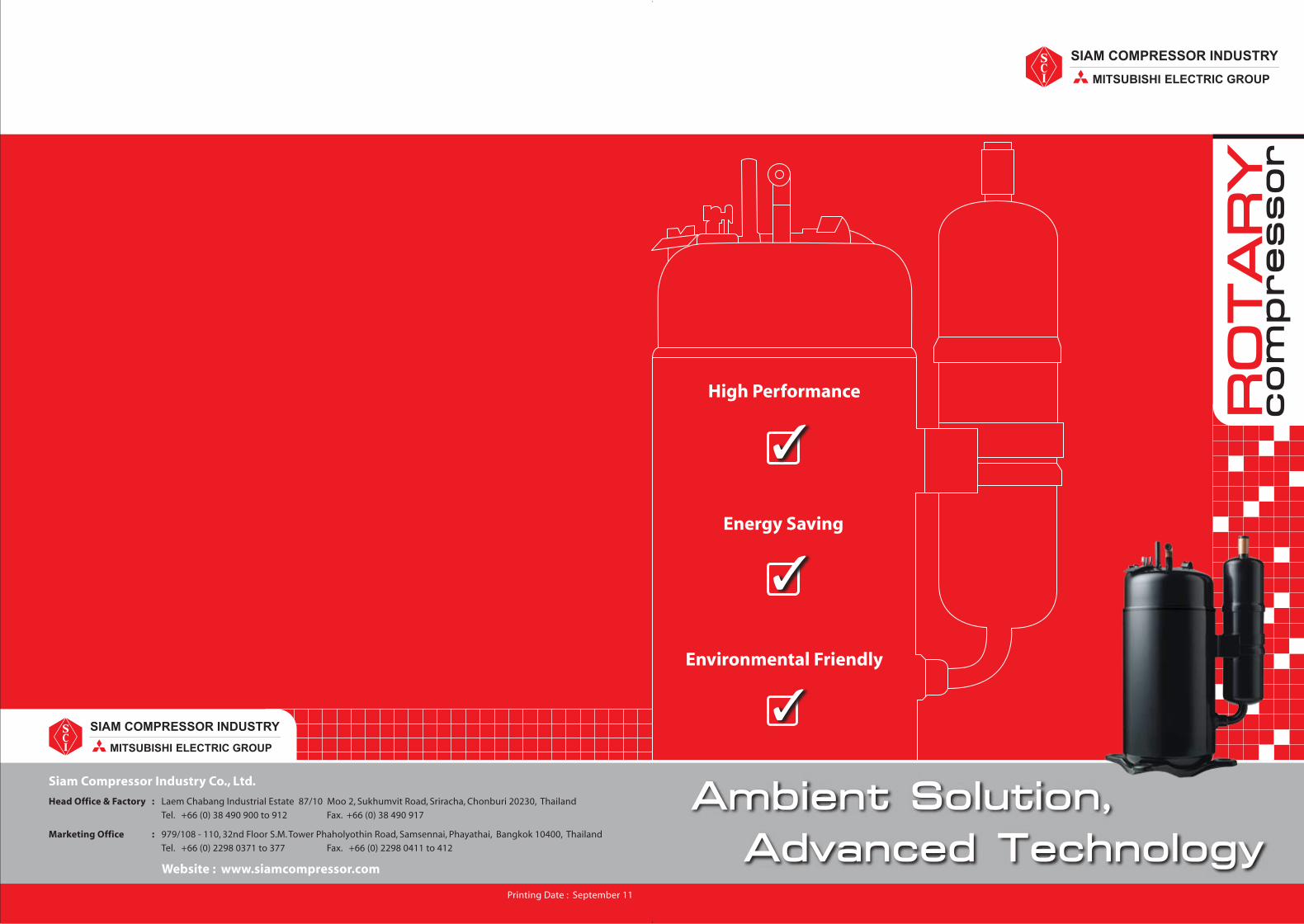
Siam Compressor Industry Co., Ltd. (SCI) is Thailand's first manufacturer of rotary compressor for room air conditioner. SCI was founded on May 25, 1990 as a subsidiary of Mitsubishi Electric Corporation of Japan, a world leader in compressor technology with over 70 years of experience. So successful was SCI in the first year of production that we were able to open a second plant only five years later, on December 16, 1995. Further milestones since then have been the inauguration of our research and development centre in 1998, the launching of a new ozone-friendly compressor that does not use HCFC coolant in 1999 and the opening of a third plant on October 16, 2002.
Since 2003, SCI has been producing Advanced Scroll Compressor utilizing Frame-Complaint Mechanism technology, thus saving energy and minimizing energy loss due to friction. SCI remains at the forefront of the global compressor industry in terms of technical progress, efficiency of production, the competence of our trained staff and our ongoing expansion.
Important Milestones
1988 : Registered the company (December 7th)
1990 : Produced the 1st Rotary Compressor of Thailand
1994 : Acquired ISO 9002
1995 : Established Factory No.2
1997 : Acquired ISO 14001
1998 : Established R & D Center
1999 : Received Prime Minister Award for Excellent Exporter and Industrial Management. First Production of R-407C spec.
2000 : Received Millennium Business Award for Environmental Achievement from UNEP and ICC
2001 : Mitsubishi Electric took over all share. Acquired TIS 18001 & ISO 9001
2002 : Reached the 10 million set - production. First Production of R-410A spec.
2002 : Established Factory No.3 and launched scroll compressor production.
2004 : Received Prime Minister Award for Excellent Productivity Management
2006 : Received TPM Award from JIPM (Japanese Institute of Plant Maintenance)
2006 : Reached the 20 million set - production. 2008 : Reached the 1 million set - scroll compressor production.
Company Profile
SIAM
COM
PRESSOR INDUSTRY CO., LTD. (SCI)
4 5
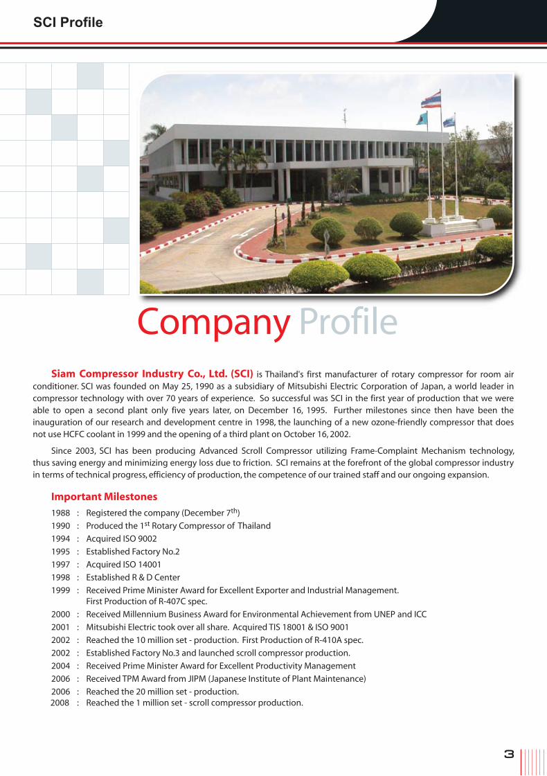
0.1 0.5 1.0 1.5 3.0 6.0 8.0 10.0
Global Mitsubishi Compressor Production Bases Rotary Compressor Benefits and Advantages
Single Rotary & Reciprocating
Twin Rotary
Inverter Single Rotary
Inverter Twin Rotary
Single Rotary
Inverter Single Rotary
Inverter Twin Rotary
Twin Rotary
Single Rotary
Inverter Twin Rotary
Scroll
Inverter Scroll
1HP 2HP 4HP 8HP 10HP 13HP
Nominal Output (kW)
Global Mitsubishi Compressor Line-Up
Compressor Line-Up
CapacityBtu/hrs
kW
16,000 24,000 26,000 28,000 32,000 36,000 40,000 44,00012,0007,500
2 3 4 5 6 7 8 9 10 11 12 13CompressorSeries
R Series
N Series
T Series
S Series
Ultra Tropical
P Series
50Hz
50Hz
50Hz
60Hz
60Hz
60Hz
60Hz
60Hz
50Hz60Hz
MITSUBISHI ELECTRIC SHIZUOKA WORKS (MELSHI)
MITSUBISHI ELECTRIC (GUANGZHOU) COMPRESSOR CO.,LTD.
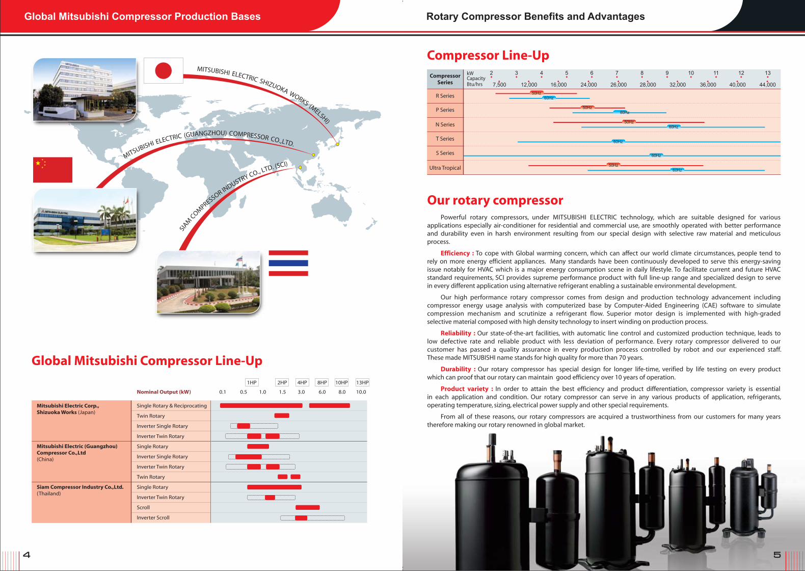
Our rotary compressorPowerful rotary compressors, under MITSUBISHI ELECTRIC technology, which are suitable designed for various
applications especially air-conditioner for residential and commercial use, are smoothly operated with better performance and durability even in harsh environment resulting from our special design with selective raw material and meticulous process.
Efficiency : To cope with Global warming concern, which can affect our world climate circumstances, people tend to rely on more energy efficient appliances. Many standards have been continuously developed to serve this energy-saving issue notably for HVAC which is a major energy consumption scene in daily lifestyle. To facilitate current and future HVAC standard requirements, SCI provides supreme performance product with full line-up range and specialized design to serve in every different application using alternative refrigerant enabling a sustainable environmental development.
Our high performance rotary compressor comes from design and production technology advancement including compressor energy usage analysis with computerized base by Computer-Aided Engineering (CAE) software to simulate compression mechanism and scrutinize a refrigerant flow. Superior motor design is implemented with high-graded selective material composed with high density technology to insert winding on production process.
Reliability : Our state-of-the-art facilities, with automatic line control and customized production technique, leads to low defective rate and reliable product with less deviation of performance. Every rotary compressor delivered to our customer has passed a quality assurance in every production process controlled by robot and our experienced staff. These made MITSUBISHI name stands for high quality for more than 70 years.
Durability : Our rotary compressor has special design for longer life-time, verified by life testing on every product which can proof that our rotary can maintain good efficiency over 10 years of operation.
Product variety : In order to attain the best efficiency and product differentiation, compressor variety is essential in each application and condition. Our rotary compressor can serve in any various products of application, refrigerants, operating temperature, sizing, electrical power supply and other special requirements.
From all of these reasons, our rotary compressors are acquired a trustworthiness from our customers for many years therefore making our rotary renowned in global market.
Mitsubishi Electric Corp.,Shizuoka Works (Japan)
Siam Compressor Industry Co.,Ltd. (Thailand)
Mitsubishi Electric (Guangzhou)Compressor Co.,Ltd (China)
6 7
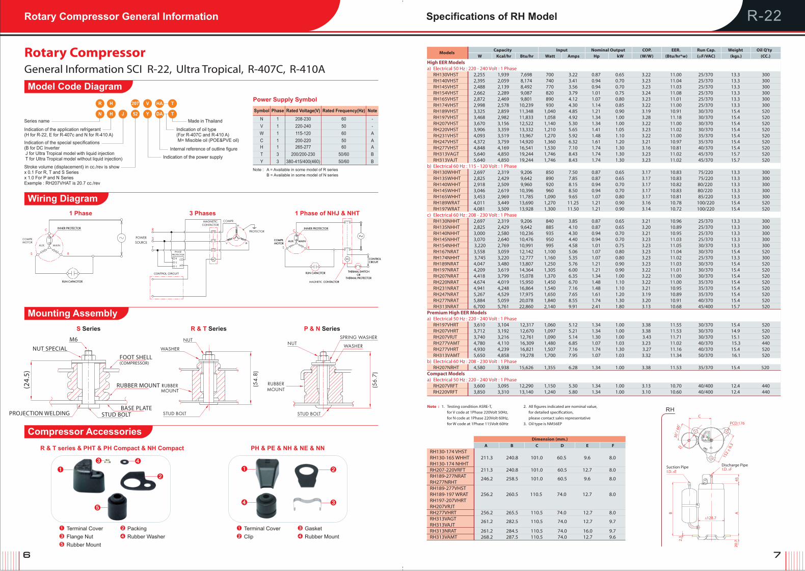
R-22Rotary Compressor General Information Specifications of RH Model
Models
Capacity Input Nominal Output COP. EER. Run Cap. Weight Oil Q'ty
W Kcal/hr Btu/hr Watt Amps Hp kW (W/W) (Btu/hr*w) (μF/VAC) (kgs.) (CC.)
Note : 1. Testing condition ASRE-T,
for V code at 1Phase 220Volt 50Hz,
for N code at 1Phase 220Volt 60Hz,
for W code at 1Phase 115Volt 60Hz
2. All figures indicated are nominal value,
for detailed specification,
please contact sales representative
3. Oil type is NM56EP
High EER Models a) Electrical 50 Hz : 220 - 240 Volt : 1 Phase RH130VHST 2,255 1,939 7,698 700 3.22 0.87 0.65 3.22 11.00 25/370 13.3 300 RH140VHST 2,395 2,059 8,174 740 3.41 0.94 0.70 3.23 11.04 25/370 13.3 300 RH145VHST 2,488 2,139 8,492 770 3.56 0.94 0.70 3.23 11.03 25/370 13.3 300 RH154VHST 2,662 2,289 9,087 820 3.79 1.01 0.75 3.24 11.08 25/370 13.3 300 RH165VHST 2,872 2,469 9,801 890 4.12 1.07 0.80 3.23 11.01 25/370 13.3 300 RH174VHST 2,998 2,578 10,239 930 4.30 1.14 0.85 3.22 11.00 25/370 13.3 300 RH189VHST 3,325 2,859 11,348 1,040 4.85 1.21 0.90 3.19 10.91 30/370 15.4 520 RH197VHST 3,468 2,982 11,833 1,058 4.92 1.34 1.00 3.28 11.18 30/370 15.4 520 RH207VHST 3,670 3,156 12,522 1,140 5.30 1.34 1.00 3.22 11.00 30/370 15.4 520 RH220VHST 3,906 3,359 13,332 1,210 5.65 1.41 1.05 3.23 11.02 30/370 15.4 520 RH231VHST 4,093 3,519 13,967 1,270 5.92 1.48 1.10 3.22 11.00 35/370 15.4 520 RH247VHST 4,372 3,759 14,920 1,360 6.32 1.61 1.20 3.21 10.97 35/370 15.4 520 RH277VHST 4,848 4,169 16,541 1,530 7.10 1.74 1.30 3.16 10.81 40/370 15.4 520 RH313VAGT 5,640 4,850 19,244 1,746 8.43 1.74 1.30 3.23 11.02 45/370 15.7 520 RH313VAJT 5,640 4,850 19,244 1,746 8.43 1.74 1.30 3.23 11.02 45/370 15.7 520b) Electrical 60 Hz : 115 - 120 Volt : 1 Phase RH130WHHT 2,697 2,319 9,206 850 7.50 0.87 0.65 3.17 10.83 75/220 13.3 300 RH135WHHT 2,825 2,429 9,642 890 7.85 0.87 0.65 3.17 10.83 75/220 13.3 300 RH140WHHT 2,918 2,509 9,960 920 8.15 0.94 0.70 3.17 10.82 80/220 13.3 300 RH145WHHT 3,046 2,619 10,396 960 8.50 0.94 0.70 3.17 10.83 80/220 13.3 300 RH165WHHT 3,453 2,969 11,785 1,090 9.65 1.07 0.80 3.17 10.81 85/220 13.3 300 RH189WRAT 4,011 3,449 13,690 1,270 11.25 1.21 0.90 3.16 10.78 100/220 15.4 520 RH197WRAT 4,081 3,509 13,928 1,300 11.50 1.21 0.90 3.14 10.72 100/220 15.4 520c) Electrical 60 Hz : 208 - 230 Volt : 1 Phase RH130NHHT 2,697 2,319 9,206 840 3.85 0.87 0.65 3.21 10.96 25/370 13.3 300 RH135NHHT 2,825 2,429 9,642 885 4.10 0.87 0.65 3.20 10.89 25/370 13.3 300 RH140NHHT 3,000 2,580 10,236 935 4.30 0.94 0.70 3.21 10.95 25/370 13.3 300 RH145NHHT 3,070 2,640 10,476 950 4.40 0.94 0.70 3.23 11.03 25/370 13.3 300 RH154NHHT 3,220 2,769 10,991 995 4.58 1.01 0.75 3.23 11.05 30/370 13.3 300 RH167NRAT 3,558 3,059 12,142 1,100 5.06 1.07 0.80 3.23 11.04 30/370 15.4 520 RH174NHHT 3,745 3,220 12,777 1,160 5.35 1.07 0.80 3.23 11.02 25/370 13.3 300 RH189NRAT 4,047 3,480 13,807 1,250 5.76 1.21 0.90 3.23 11.03 30/370 15.4 520 RH197NRAT 4,209 3,619 14,364 1,305 6.00 1.21 0.90 3.22 11.01 30/370 15.4 520 RH207NRAT 4,418 3,799 15,078 1,370 6.35 1.34 1.00 3.22 11.00 30/370 15.4 520 RH220NRAT 4,674 4,019 15,950 1,450 6.70 1.48 1.10 3.22 11.00 35/370 15.4 520 RH231NRAT 4,941 4,248 16,864 1,540 7.16 1.48 1.10 3.21 10.95 35/370 15.4 520 RH247NRAT 5,267 4,529 17,975 1,650 7.65 1.61 1.20 3.19 10.89 35/370 15.4 520 RH277NRAT 5,884 5,059 20,078 1,840 8.55 1.74 1.30 3.20 10.91 40/370 15.4 520 RH313NRAT 6,700 5,761 22,860 2,140 9.91 2.41 1.80 3.13 10.68 45/400 15.7 520Premium High EER Models a) Electrical 50 Hz : 220 - 240 Volt : 1 Phase RH197VHRT 3,610 3,104 12,317 1,060 5.12 1.34 1.00 3.38 11.55 30/370 15.4 520 RH207VHRT 3,712 3,192 12,670 1,097 5.21 1.34 1.00 3.38 11.53 30/370 14.9 520 RH207VRJT 3,740 3,216 12,761 1,090 5.14 1.30 1.00 3.43 11.71 30/370 15.1 520 RH277VAMT 4,780 4,110 16,309 1,480 6.85 1.07 1.03 3.23 11.02 40/370 15.3 440 RH277VHRT 4,930 4,239 16,821 1,507 7.16 1.74 1.30 3.27 11.16 40/370 15.4 520 RH313VAMT 5,650 4,858 19,278 1,700 7.95 1.07 1.03 3.32 11.34 50/370 16.1 520b) Electrical 60 Hz : 208 - 230 Volt : 1 Phase RH207NRHT 4,580 3,938 15,626 1,355 6.28 1.34 1.00 3.38 11.53 35/370 15.4 520 Compact Models a) Electrical 50 Hz : 220 - 240 Volt : 1 Phase RH207VRFT 3,600 3,095 12,290 1,150 5.30 1.34 1.00 3.13 10.70 40/400 12.4 440 RH220VRFT 3,850 3,310 13,140 1,240 5.80 1.34 1.00 3.10 10.60 40/400 12.4 440
Dimension (mm.)
A B C D E F
RH130-174 VHST RH130-165 WHHT 211.3 240.8 101.0 60.5 9.6 8.0 RH130-174 NHHT RH207-220VRFT 211.3 240.8 101.0 60.5 12.7 8.0 RH189-277NRAT 246.2 258.5 101.0 60.5 9.6 8.0 RH277NRHT RH189-277VHST RH189-197 WRAT 256.2 260.5 110.5 74.0 12.7 8.0 RH197-207VHRT RH207VRJT RH277VHRT 256.2 265.5 110.5 74.0 12.7 8.0 RH313VAGT 261.2 282.5 110.5 74.0 12.7 9.7 RH313VAJT RH313NRAT 261.2 284.5 110.5 74.0 16.0 9.7 RH313VAMT 268.2 287.5 110.5 74.0 12.7 9.6
RH
PCD.176
152
+ 0.
3_
30˚/
60˚
D
C
I.D. ΔFDischarge Pipe
Δ128.7
I.D. ΔESuction Pipe
45AB
2.3
20.7
General Information SCI R-22, Ultra Tropical, R-407C, R-410A
R & T series & PHT & PH Compact & NH Compact
➊ Terminal Cover ➋ Packing
➌ Flange Nut ➍ Rubber Washer
➎ Rubber Mount
➊ Terminal Cover ➌ Gasket
➋ Clip ➍ Rubber Mount
PH & PE & NH & NE & NN
➊➊➋
➋➌ ➍
➎➌➍
Rotary Compressor
R & T SeriesS Series P & N Series
Wiring Diagram
Model Code Diagram
Mounting Assembly
Compressor Accessories
1 Phase 3 Phases
CONTROL CIRCUIT
1 Phase of NHJ & NHT
R
N
H
H J
207
52
V
Y
HA
DA
T
T
Series name Made in Thailand
Indication of the application refrigerant(H for R-22, E for R-407c and N for R-410 A)
Indication of oil type(For R-407C and R-410 A) M= Miscible oil (POE&PVE oil)Indication of the special specifications
(B for DC Inverter J for Ultra Tropical model with liquid injection T for Ultra Tropical model without liquid injection)
Internal reference of outline figure
Stroke volume (displacement) in cc./rev is showx 0.1 For R, T and S Seriesx 1.0 For P and N SeriesExemple : RH207VHAT is 20.7 cc./rev
Indication of the power supply
Power Supply Symbol
Symbol
N
Y
T
HC
W
V
Phase
1
3
3
11
1
1
Rated Voltage(V)
208-230
380-415/400(460)
200/200-230
265-277200-220
115-120
220-240
Rated Frequency(Hz)
60
50/60
50/60
6050
60
50
Note
-
B
B
AA
A
-
Note : A = Available in some model of R series B = Available in some model of N series
M6
NUT SPECIALFOOT SHELL(COMPRESSOR)
(24.
5)
RUBBER MOUNT
BASE PLATESTUD BOLTPROJECTION WELDING
8 9
Dimension (mm.)
A B D E F H
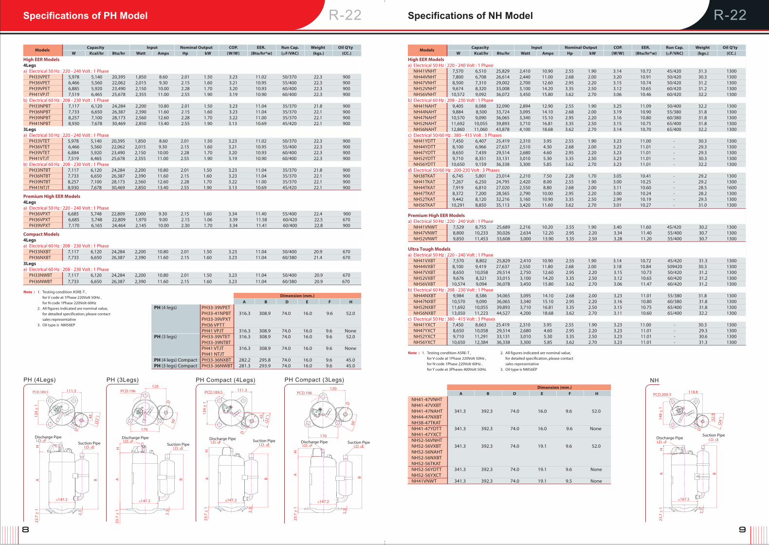
R-22 R-22Specifications of PH Model Specifications of NH Model
Models
Capacity Input Nominal Output COP. EER. Run Cap. Weight Oil Q'ty
W Kcal/hr Btu/hr Watt Amps Hp kW (W/W) (Btu/hr*w) (μF/VAC) (kgs.) (CC.)
High EER Models 4Legsa) Electrical 50 Hz : 220 - 240 Volt : 1 Phase PH33VPET 5,978 5,140 20,395 1,850 8.60 2.01 1.50 3.23 11.02 50/370 22.3 900 PH36VPET 6,466 5,560 22,062 2,015 9.30 2.15 1.60 3.21 10.95 55/400 22.3 900 PH39VPET 6,885 5,920 23,490 2,150 10.00 2.28 1.70 3.20 10.93 60/400 22.3 900 PH41VPJT 7,519 6,465 25,678 2,355 11.00 2.55 1.90 3.19 10.90 60/400 22.3 900 b) Electrical 60 Hz : 208 - 230 Volt : 1 Phase PH33NPBT 7,117 6,120 24,284 2,200 10.80 2.01 1.50 3.23 11.04 35/370 21.8 900 PH36NPBT 7,733 6,650 26,387 2,390 11.60 2.15 1.60 3.23 11.04 35/370 22.1 900 PH39NPBT 8,257 7,100 28,173 2,560 12.60 2.28 1.70 3.22 11.00 35/370 22.1 900 PH41NPBT 8,930 7,678 30,469 2,850 13.40 2.55 1.90 3.13 10.69 45/420 22.1 900 3Legs a) Electrical 50 Hz : 220 - 240 Volt : 1 Phase PH33VTET 5,978 5,140 20,395 1,850 8.60 2.01 1.50 3.23 11.02 50/370 22.3 900 PH36VTET 6,466 5,560 22,062 2,015 9.30 2.15 1.60 3.21 10.95 55/400 22.3 900 PH39VTET 6,884 5,920 23,490 2,150 10.00 2.28 1.70 3.20 10.93 60/400 22.3 900 PH41VTJT 7,519 6,465 25,678 2,355 11.00 2.55 1.90 3.19 10.90 60/400 22.3 900 b) Electrical 60 Hz : 208 - 230 Volt : 1 Phase PH33NTBT 7,117 6,120 24,284 2,200 10.80 2.01 1.50 3.23 11.04 35/370 21.8 900 PH36NTBT 7,733 6,650 26,387 2,390 11.60 2.15 1.60 3.23 11.04 35/370 22.1 900 PH39NTBT 8,257 7,100 28,173 2,560 12.60 2.28 1.70 3.22 11.00 35/370 22.1 900 PH41NTJT 8,930 7,678 30,469 2,850 13.40 2.55 1.90 3.13 10.69 45/420 22.1 900 Premium High EER Models 4Legs a) Electrical 50 Hz : 220 - 240 Volt : 1 Phase PH36VPXT 6,685 5,748 22,809 2,000 9.30 2.15 1.60 3.34 11.40 55/400 22.4 900 PH36VPXT 6,685 5,748 22,809 1,970 9.00 2.15 1.06 3.39 11.58 60/420 22.5 670 PH39VPXT 7,170 6,165 24,464 2,145 10.00 2.30 1.70 3.34 11.41 60/400 22.8 900 Compact Models 4Legs a) Electrical 60 Hz : 208 - 230 Volt : 1 Phase PH33NXBT 7,117 6,120 24,284 2,200 10.80 2.01 1.50 3.23 11.04 50/400 20.9 670 PH36NXBT 7,733 6,650 26,387 2,390 11.60 2.15 1.60 3.23 11.04 60/380 21.4 670 3Legs a) Electrical 60 Hz : 208 - 230 Volt : 1 Phase PH33NWBT 7,117 6,120 24,284 2,200 10.80 2.01 1.50 3.23 11.04 50/400 20.9 670 PH36NWBT 7,733 6,650 26,387 2,390 11.60 2.15 1.60 3.23 11.04 60/380 20.9 670
Note : 1. Testing condition ASRE-T ,
for V code at 1Phase 220Volt 50Hz ,
for N code 1Phase 220Volt 60Hz
2. All figures indicated are nominal value,
for detailed specification, please contact
sales representative
3. Oil type is NM56EP
Models
Capacity Input Nominal Output COP. EER. Run Cap. Weight Oil Q'ty
W Kcal/hr Btu/hr Watt Amps Hp kW (W/W) (Btu/hr*w) (μF/VAC) (kgs.) (CC.)
High EER Models a) Electrical 50 Hz : 220 - 240 Volt : 1 Phase NH41VNHT 7,570 6,510 25,829 2,410 10.90 2.55 1.90 3.14 10.72 45/420 31.3 1300 NH44VNHT 7,800 6,708 26,614 2,440 11.00 2.68 2.00 3.20 10.91 50/420 30.3 1300 NH47VNHT 8,500 7,310 29,002 2,700 12.60 2.95 2.20 3.15 10.74 50/420 31.2 1300 NH52VNHT 9,674 8,320 33,008 3,100 14.20 3.35 2.50 3.12 10.65 60/420 31.2 1300 NH56VNHT 10,572 9,092 36,072 3,450 15.80 3.62 2.70 3.06 10.46 60/420 32.2 1300b) Electrical 60 Hz : 208 - 230 Volt : 1 Phase NH41NAHT 9,405 8,088 32,090 2,894 12.90 2.55 1.90 3.25 11.09 50/400 32.2 1300 NH44NAHT 9,884 8,500 33,724 3,095 14.10 2.68 2.00 3.19 10.90 55/380 31.8 1300 NH47NAHT 10,570 9,090 36,065 3,340 15.10 2.95 2.20 3.16 10.80 60/380 31.8 1300 NH52NAHT 11,692 10,055 39,893 3,710 16.81 3.35 2.50 3.15 10.75 65/400 31.8 1300 NH56NAHT 12,860 11,060 43,878 4,100 18.68 3.62 2.70 3.14 10.70 65/400 32.2 1300c) Electrical 50/60 Hz : 380 - 415 Volt : 3 Phases NH41YDTT 7,450 6,407 25,419 2,310 3.95 2.55 1.90 3.23 11.00 - 30.3 1300 NH44YDTT 8,100 6,966 27,637 2,510 4.30 2.68 2.00 3.23 11.01 - 29.3 1300 NH47YDTT 8,650 7,439 29,514 2,680 4.60 2.95 2.20 3.23 11.01 - 29.3 1300 NH52YDTT 9,710 8,351 33,131 3,010 5.30 3.35 2.50 3.23 11.01 - 30.3 1300 NH56YDTT 10,650 9,159 36,338 3,300 5.85 3.62 2.70 3.23 11.01 - 32.2 1300d) Electrical 50/60 Hz : 200-230 Volt : 3 Phases NH38TKAT 6,745 5,801 23,014 2,210 7.50 2.28 1.70 3.05 10.41 - 29.2 1300 NH41TKAT 7,267 6,250 24,795 2,420 8.00 2.55 1.90 3.00 10.25 - 29.2 1300 NH44TKAT 7,919 6,810 27,020 2,550 8.80 2.68 2.00 3.11 10.60 - 28.5 1600 NH47TKAT 8,372 7,200 28,565 2,790 10.00 2.95 2.20 3.00 10.24 - 28.2 1300 NH52TKAT 9,442 8,120 32,216 3,160 10.90 3.35 2.50 2.99 10.19 - 29.3 1300 NH56TKAT 10,291 8,850 35,113 3,420 11.60 3.62 2.70 3.01 10.27 - 31.0 1300
Premium High EER Models a) Electrical 50 Hz : 220 - 240 Volt : 1 Phase NH41VNWT 7,529 8,755 25,689 2,216 10.20 2.55 1.90 3.40 11.60 45/420 30.2 1300 NH47VNWT 8,800 10,233 30,026 2,634 12.20 2.95 2.20 3.34 11.40 55/400 30.7 1300 NH52VNWT 9,850 11,453 33,608 3,000 13.90 3.35 2.50 3.28 11.20 55/400 30.7 1300
Ultra Tough Models a) Electrical 50 Hz : 220 - 240 Volt : 1 Phase NH41VXBT 7,570 8,802 25,829 2,410 10.90 2.55 1.90 3.14 10.72 45/420 31.3 1300 NH44VXBT 8,100 9,419 27,637 2,550 11.80 2.68 2.00 3.18 10.84 509420 30.3 1300 NH47VXBT 8,650 10,058 29,514 2,750 12.60 2.95 2.20 3.15 10.73 50/420 31.2 1300 NH52VXBT 9,676 8,321 33,015 3,100 14.20 3.35 2.50 3.12 10.65 60/420 31.2 1300 NH56VXBT 10,574 9,094 36,078 3,450 15.80 3.62 2.70 3.06 11.47 60/420 31.2 1300b) Electrical 60 Hz : 208 - 230 Volt : 1 Phase NH44NXBT 9,984 8,586 34,065 3,095 14.10 2.68 2.00 3.23 11.01 55/380 31.8 1300 NH47NXBT 10,570 9,090 36,065 3,340 15.10 2.95 2.20 3.16 10.80 60/380 31.8 1300 NH52NXBT 11,692 10,055 39,893 3,710 16.81 3.35 2.50 3.15 10.75 65/400 31.8 1300 NH56NXBT 13,050 11,223 44,527 4,200 18.68 3.62 2.70 3.11 10.60 65/400 32.2 1300c) Electrical 50 Hz : 380 - 415 Volt : 3 Phases NH41YXCT 7,450 8,663 25.419 2,310 3.95 2.55 1.90 3.23 11.00 - 30.3 1300 NH47YXCT 8,650 10,058 29,514 2,680 4.60 2.95 2.20 3.23 11.01 - 29.3 1300 NH52YXCT 9,710 11,291 33,131 3,010 5.30 3.35 2.50 3.23 11.01 - 30.6 1300 NH56YXCT 10,650 12,384 36,338 3,300 5.85 3.62 2.70 3.23 11.01 - 31.3 1300
Note : 1. Testing condition ASRE-T ,
for V code at 1Phase 220Volt 50Hz ,
for N code 1Phase 220Volt 60Hz ,
for Y code at 3Phases 400Volt 50Hz.
2. All figures indicated are nominal value,
for detailed specification, please contact
sales representative
3. Oil type is NM56EP
PH (4 legs) PH33-39VPET PH33-41NPBT 316.3 308.9 74.0 16.0 9.6 52.0 PH33-39VPXT PH36 VPTT PH41 VPJT 316.3 308.9 74.0 16.0 9.6 None PH (3 legs) PH33-39VTET 316.3 308.9 74.0 16.0 9.6 52.0 PH33-39NTBT PH41 VTJT 316.3 308.9 74.0 16.0 9.6 None PH41 NTJT PH (4 legs) Compact PH33-36NXBT 282.2 295.8 74.0 16.0 9.6 45.0 PH (3 legs) Compact PH33-36NWBT 281.3 293.9 74.0 16.0 9.6 45.0
NH
I.D. ΔFDischarge Pipe
PCD.209.3118.8
D
52.9
148
+ 1
_
I.D. ΔESuction Pipe
HA B
Δ167.5
2.3
23.7
+ 1
_
(24˚
)
NH41-47VNHT NH41-47VXBT NH41-47NAHT 341.3 392.3 74.0 16.0 9.6 52.0 NH44-47NXBT NH38-47TKAT NH41-47YDTT 341.3 392.3 74.0 16.0 9.6 None NH41-47YXCT NH52-56VNHT NH52-56VXBT 341.3 392.3 74.0 19.1 9.6 52.0 NH52-56NAHT NH52-56NXBT NH52-56TKAT NH52-56YDTT 341.3 392.3 74.0 19.1 9.6 None NH52-56YXCT NH41VNWT 341.3 392.3 74.0 19.1 9.5 None
Dimension (mm.)
A B D E F H
I.D. ΔFDischarge Pipe
I.D. ΔESuction Pipe
H
B
A
Δ147.2
2.3
23.7
+ 1
_
PCD.196120
D
170
30˚
PH Compact (3Legs)
H
I.D. ΔFDischarge Pipe
I.D. ΔESuction Pipe
BA
Δ147.2
2.3
111.3
45(2
2˚)13
4 +
1_
D
PCD.189.5
23.7
+ 1
_
PH Compact (4Legs)
I.D. ΔFDischarge Pipe
120
170
I.D. ΔESuction Pipe
B
30˚
AH
Δ147.2
23.7
+ 1
_ 2.3
PCD.196
D
PH (3Legs)
111.3
45
I.D. ΔESuction Pipe
B(2
2˚)
AH
Δ147.2
134
+ 1
_
2.3
PCD.189.5
D
23.7
+ 1
_
I.D. ΔFDischarge Pipe
PH (4Legs)

10 11
3.500
3.000
2.500
2.000
1.500
1.000
0.500
0.0000.000 0.100 0.200 0.300 0.400 0.500 .0.600 0.700 0.800
Operation Area of Ultra Tropical model
Suction Pressure (MPaG.)
Dis
char
ge
Pres
sure
(MPa
G.)
Compression Ratio = 8
(CT = 28)
(CT = 71)
(ET = -20) (ET = -10) (ET = -15) (ET = -15)
(CT = 76)
0.281, 2.958
0.254, 2.737
0.254, 1.030 0.688, 1.030
0.688, 2.958
0.688, 3.2170.313, 3.217
0.144, 1.861
Transient
0.144, 1.030
Operation Standards and Limits ofR-22 Compressor RH, PH, NH Model Ultra Tropical Compressor Information
Models RH PH NH Compressor Type Rolling Piston Type Rotary Displacement (cc/rev.) 13.0~31.3 28.1~44.1 28.1~38.8, 41.8~56.9 Refrigerant type R-22Pressure Maximum Condensing 26.5 kg/cm2G /65˚C (377 psiG/149˚F) Evaporating 2.61~7.05 kg/cm2G (37 ~ 100 psiG) Compression Ratio 6 or less 8 or less (See Note1) Abnormal Rise in pressure 40 kg/cm2G (569 psiG) or less (According to JIS BB620 Critical Pressure limit is 42 kg/cm2G for fan block)Temperature Condensing 28˚C ~ 65˚C (82.4˚F~149˚F) Evaporating -10˚C ~ 15˚C (14˚F ~ 59˚F) Discharged Gas (max) 120˚C(248˚F), In case of Heat pump or De-humidipier, this limit is 115˚C(239˚F) (See Note 2) Suction Gas (max) must be over 0˚C (No liquid back) (See Note 2) Discharged gas's superheat 20˚C or more Outdoor Ambient Temp. Air cond :20˚C ~ 43 ˚C (68˚F ~ 109.4˚F) Heat Pump : -10˚C ~ 43 ˚C(14˚F ~ 109.4˚F)Electrical Supply voltage during operation Rated voltage ±10% Starting voltage Minimum 80% of rated voltage (at 10.3 kg/cm2G balancing pressure) In case of 208-230 V Rated Voltage (N-code compressor), the starting voltage shall be 85% or more. This shall be measured at compressor termin. Reverse Phase (Rotation) Not possible Frequency range Rated Frequency ±2%ON/OFF ON/OFF Frequency Less than 170,000 cycles ON/OFF Cycle The ON/OFF cycle shall be a maximum of 10 time/hour. OFF time shall be the time until the high side pressure reach to balance pressure (more than 3 min) Pipe Stress 3.5 kg/mm2 or less at start and stop condition (1.8 kg/mm2 during operation)Refrigerant Circuit Maximum Refrigerant Charge See in General Spec Evacuation level Degree of vaccum equivalent to about 133 Pa (abs) (1.0 mmHg) Piping length between Max. 15 m. for RH130 - RH165 Max. 30 m. ( for Ultra Tough Model, Max. 50 m.) indoor and outdoor units Max. 20 m. for RH167 - RH 313 (See also Note 3) Elevation between Max. 7 m. for RH130 - RH165 Max. 30 m. indoor and outdoor units Max. 15 m. for RH167 - RH 313 (See also Note 3) Piping Vibration Maximum 0.8 mm. Inclination of compressor Within 5˚
Note : 1. High compression ratio test ; C.T./E.T. = 62/-12°C ; has been performed already.
2. The temperature must be lower than this critical value even the unit has been using for many years.
3. These Piping Length and Elevation for all seriesare based on pipe size following this ;
Liquid : Ø 9.52 mm. (3/8") Gas : Ø15.88 mm. (5/8")
Condition Application :
Application Range ASRE - T Rating Condition • Evaporating Temperature Range -10°C to 15 °C (14°F to 59 °F) • Evaporating Temperature 7.2°C (45°F) • Condensing Temperature Range 28°C to 65 °C (82.4°F to 149 °F) • Return Gas Temperature 35.0°C (95°F) • Refrigerant R-22 • Condensing Temperature 54.4°C (130°F) • Discharge Gas Temperature 120 °C (248°F) max. for Air Cond • Liquid Temperature 46.1°C (115°F) 115 °C (239°F) max. for Heat Pump • Ambient Temperature 35.0°C (95°F)
These ultra tropical rotary compressors which are suitably invented for high ambient zone, are prized for their extremely high reliable mechanism bringing to longer product life-time, powerful motor with compact size and light weight. All of these ultra tropical advanced features are resulting from our tropical market insight and our expert technology owned by MITSUBISHI ELECTRIC.
• Higher operating ambient temperature
up to 54˚C (CT~71˚C & CT~76˚C for transient)
• Higher operating pressure
(up to 3.22 MPaG or 468.5 psiG). These ultra tropical compressors can superbly perform even in the very high temperature such as desert area. The well designed compressors are an ideal solution for every air-conditioning system in the world toughest tropical zone.
• Mechanical part strenghtening
During high ambient temperature operation, parts of compressor contacting together are corrosion easily. With Mitsubishi technology, all critical parts are treated with specialized material and specific hardening process causing compressor to be more durable.
• High torque motor
Get greatest efficency from the high performance motor with our ultra tropical compressor, which torque optimized for higher high temperature condition.
Our ultra topical model comprises of Non-Liquid Injection model and Liquid Injection model.
The non-liquid injection model is designed for smaller capacity, with special motor that is able to withstand high temperature operation without extra cooling down feature.
The Liquid injection model is specially designed for higher motor capacity that liquid refrigerant injecting is needed to reduce an extremely high temperature in limited area of operation.
What are the Ultra Tough compressors?
‘Ultra Tough’ are rotary compressors which are suitably invented for using in serve conditions. Its extremely high durable and reliable mechanism can benefit to enchance product life-time, powerful motor with compact size and lightweight (~20% lower weight when compare with reciprocating compressor at the same cooling capacity)
Ultra Tough is the latest technology of rotary compressor which has a specialty designed by adding new Oil circulation reduction mechanism that will result in the avoidance of oil out problem and the using of new alloy bearing to increase durability and help to protect liquid back and short starting problem. From our compressor expertise and our experience in tropical design with full array of modern production line bring
our ultra tropical compressor to be the genuine tropical compressor in the market.
R-22 R-22
Non-Liquid Injection model Liquid Injection model
12 13
Dimension (mm.)
A B D E F
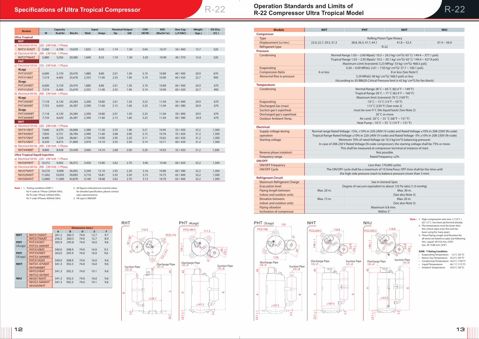
R-22 R-22Operation Standards and Limits ofR-22 Compressor Ultra Tropical Model Specifications of Ultra Tropical Compressor
Models
Capacity Input Nominal Output COP. EER. Run Cap. Weight Oil Q'ty
W Kcal/hr Btu/hr Watt Amps Hp kW (W/W) (Btu/hr*w) (μF/VAC) (kgs.) (CC.)
Note : 1. Testing condition ASRE-T ,
for V code at 1Phase 220Volt 50Hz ,
for N code 1Phase 220Volt 60Hz ,
for Y code 3Phases 400Volt 50Hz
2. All figures indicated are nominal value,
for detailed specification, please contact
sales representative
3. Oil type is NM56EP
Note : 1. High compression ratio test ; C.T./E.T. = 62/-12˚C ; has been performed already. 2. The temperature must be lower than this critical value even the unit has been using for many years. 3. These Piping Length and Elevation for all series are based on pipe size following this ; Liquid : Ø 9.52 mm. (3/8") Gas : Ø 15.88 mm. (5/8")
ASRE - T Rating Condition • Evaporating Temperature 7.2˚C (45˚F) • Return Gas Temperature 35.0˚C (95˚F) • Condensing Temperature 54.4˚C (130˚F) • Liquid Temperature 46.1˚C (115˚F) • Ambient Temperature 35.0˚C (95˚F)
Ultra Tropical RHT a) Electrical 50 Hz : 220 - 240 Volt : 1 Phase RHT313VADT 5,580 4,798 19,039 1,835 8.50 1.74 1.30 3.04 10.37 50 / 400 15.7 520 b) Electrical 60 Hz : 208 - 230 Volt : 1 Phase RHT277NAAT 5,880 5,056 20,080 1,840 8.55 1.74 1.30 3.20 10.90 40 / 370 15.4 520 PHT a) Electrical 50 Hz : 220 - 240 Volt : 1 Phase 4Legs PHT33VXET 6,000 5,159 20,470 1,880 8.80 2.01 1.50 3.19 10.89 60 / 400 20.9 670 PHT41VBAT 7,519 6,465 25,678 2,355 11.00 2.55 1.90 3.19 10.90 60 / 420 22.7 900 3Legs PHT33VWET 6,000 5,159 20,470 1,880 8.80 2.01 1.50 3.19 10.89 60 / 400 20.9 670 PHT41VDAT 7,519 6,465 25,678 2,355 11.00 2.55 1.90 3.19 10.90 60 / 420 22.7 900b) Electrical 60 Hz : 208 - 230 Volt : 1 Phase 4Legs PHT33NXBT 7,118 6,120 24,284 2,200 10.80 2.01 1.50 3.23 11.04 50 / 400 20.9 670 PHT36NXBT 7,733 6,650 26,387 2,390 11.60 2.15 1.60 3.23 11.04 60 / 380 20.9 670 3Legs PHT33NWBT 7,118 6,120 24,284 2,200 10.80 2.01 1.50 3.23 11.04 50 / 400 20.9 670 PHT36NWBT 7,734 6,650 26,387 2,390 11.60 2.15 1.60 3.23 11.04 60 / 380 20.9 670 NHT a) Electrical 50 Hz : 220 - 240 Volt : 1 Phase NHT41VBAT 7,640 6,570 26,068 2,380 11.20 2.55 1.90 3.21 10.95 55 / 420 32.2 1,300 NHT44VBAT 7,850 6,751 26,784 2,490 11.60 2.68 2.00 3.15 10.76 55 / 420 31.2 1,300 NHT47VBAT 8,400 7,224 28,661 2,700 13.00 2.95 2.20 3.11 10.62 60 / 420 31.2 1,300 NHT52VBAT 9,320 8,015 31,800 2,970 14.10 3.35 2.50 3.14 10.71 60 / 420 31.2 1,300b) Electrical 60 Hz : 208 - 230 Volt : 1 Phase NHT44NBBT 9,800 8,428 33,438 3,060 14.10 2.68 2.00 3.20 10.93 55 / 420 31.2 1,300
Ultra Tropical liquid Injectiona) Electrical 50 Hz : 220 - 240 Volt : 1 Phase NHJ56VNHT 10,572 9,092 36,072 3,450 15.80 3.62 2.70 3.06 10.46 60 / 420 32.2 1,300b) Electrical 60 Hz : 208 - 230 Volt : 1 Phase NHJ47NAHT 10,570 9,090 36,065 3,340 15.10 2.95 2.20 3.16 10.80 60 / 380 32.2 1,300 NHJ52NAHT 11,692 10,055 39,893 3,710 16.81 3.35 2.50 3.15 10.75 65 / 400 32.2 1,300 NHJ56NAHT 12,860 11,060 43,878 4,100 18.68 3.62 2.70 3.13 10.70 65 / 400 32.2 1,300
RHT RHT313VADT 261.2 282.5 74.0 12.7 9.7 RHT277NAAT 256.2 260.5 74.0 12.7 8.0 PHT PHT33VXET 305.9 295.8 74.0 16.0 9.6 (4Legs) PHT33-36NXBT PHT41VBAT 340.0 308.9 74.0 16.0 9.5 PHT PHT33VWET 303.0 293.9 74.0 16.0 9.6 (3Legs) PHT33-36NWBT PHT41VDAT 340.0 308.9 74.0 16.0 9.6 NHT NHT41-47VBAT 341.3 392.3 74.0 16.0 9.6 NHT44NBBT NHT52VBAT 341.3 392.3 74.0 19.1 9.6 NHT52-56YBAT NHJ NHJ47 NAHT 341.3 392.3 74.0 16.0 9.6 NHJ52-56NAHT 341.3 392.3 74.0 19.1 9.6 NHJ56VNHT
Models RHT PHT NHT NHJCompressor Type Rolling Piston Type Rotary Displacement (cc/rev.) 22.0, 22.7, 29.5, 31.3 38.8, 36.5, 41.7, 44.1 41.8 ~ 52.4 47.4 ~ 56.9 Refrigerant type R-22Pressure Condensing Normal Range 1.03 ~ 2.60 MpaG/ 10.5 ~ 26.5 kg/ cm2G/ 65˚C/ 149.4 ~ 377.1 psiG Tropical Range 1.03 ~ 2.95 MpaG/ 10.5 ~ 30.1 kg/ cm2G/ 65˚C/ 149.4 ~ 427.9 psiG Maximum Limit (transient) 3.23 MPag/ 33 kg/ cm2G/ 468.5 psiG Evaporating 0.26 ~ 0.69 MPaG/ 2.61 ~ 7.05 kg/ cm2G/ 37.7 ~ 100.1 psiG Compression Ratio 6 or less 8 or less (See Note1) Abnormal Rise in pressure 3.29 MPaG/ 40 kg/ cm2G/ 568.5 psiG or less (According to JIS BB620 Critical Pressure limit is 42 kg/ cm2G for fan block)Temperature Condensing Normal Range 28˚C ~ 65˚C (82.4˚F ~ 149˚F) Tropical Range 28˚C ~ 71˚C (82.4˚F ~ 160˚F) Maximum limit (transient) 76˚C (169˚F) Evaporating -10˚C ~ 15˚C (14˚F ~ 59˚F) Discharged Gas (max) 115˚C (239˚F) (See note 2) Suction gas's superheat must be over 0˚C (No liquid back) (See Note 2) Discharged gas's superheat 20˚C or more Outdoor Ambient Temp. Air cond : 20˚C ~ 55 ˚C (68˚F ~ 131˚F) Heat Pump : -10˚C ~ 55 ˚C (14˚F ~ 131˚F) Electrical Supply voltage during Normal range Rated Voltage -15%, +10% in 220-240V (V-code) and Rated Voltage ±10% in 208-230V (N-code) operation Tropical Range Rated Voltage ±10% in 220-240V (V-code) and Rated Voltage -5% ±10% in 208-230V (N-code) Starting voltage Minimum 70% of rated Voltage (at 10.3 kg/cm2G balancing pressure) In case of 208-230 V Rated Voltage (N-code compressor), the starting voltage shall be 75% or more. This shall be measured at compressor terminal at instance of start. Reverse phase (rotation) Not possible Frequency range Rated Frequency ±2%ON/OFF ON/OFF Frequency Less than 170,000 cycles ON/OFF Cycle The ON/OFF cycle shall be a maximum of 10 time/hour. OFF time shall be the time until the high side pressure reach to balance pressure (more than 3 min)Refrigerant Circuit Maximum Refrigerant Charge See in General Spec Evacuation level Degree of vaccum equivalent to about 133 Pa (abs) (1.0 mmHg) Piping length between Max. 20 m. Max. 30 m. indoor and outdoor units (See also Note 3) Elevation between Max. 15 m. Max. 20 m. indoor and outdoor units (See also Note 3) Piping vibration Maximum 0.8 mm. Inclination of compressor Within 5˚
RHT NHT NHJPHT (4Legs) PHT (3Legs)
110.5
45A
23.7
+ 1
_ 2.3
B
Δ147.2
I.D. ΔEI.D. ΔFDischarge Pipe
Suction Pipe Suction Pipe
111.3
45
(22˚
)
D
134
+ 1
_
PCD.189.5 PCD.196
120
170
I.D. ΔE
45A B
2.3
23.7
+ 1
_
Δ147.2
30˚
D
PCD.176
152
+ 0.
3_
30˚/
60˚
D
I.D. ΔFDischarge Pipe I.D. ΔF
Discharge Pipe
Δ128.7
I.D. ΔESuction Pipe
45AB
2.3
20.7
I.D. ΔFDischarge Pipe
I.D. ΔESuction Pipe
B
118.8PCD.209.3
D
148
+ 1
_
52.9
(24˚
)
45A
Δ167.5
23.7
+ 1
_ 2.3
I.D. ΔFDischarge Pipe
2.3
23.7
+ 1
_
PCD.209.3118.8
148
+ 1
_
D
(24˚
)
52.9
I.D. ΔESuction Pipe
45A B
Δ167.5
14 15
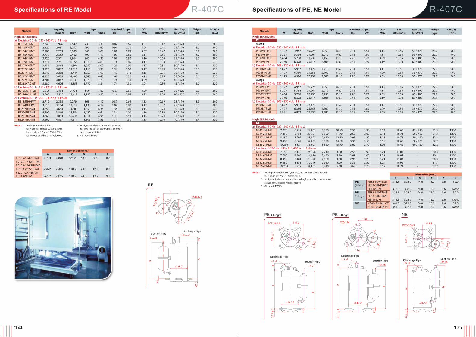
R-407C R-407CSpecifications of RE Model Specifications of PE, NE Model
Models
Capacity Input Nominal Output COP. EER. Run Cap. Weight Oil Q'ty
W Kcal/hr Btu/hr Watt Amps Hp kW (W/W) (Btu/hr*w) (μF/VAC) (kgs.) (CC.)
Note : 1. Testing condition ASRE-T,
for V code at 1Phase 220Volt 50Hz,
for N code at 1Phase 220Volt 60Hz,
for W code at 1Phase 115Volt 60Hz
2. All figures indicated are nominal value,
for detailed specification, please contact
sales representative
3. Oil type is FV50S
High EER Models a) Electrical 50 Hz : 220 - 240 Volt : 1 Phase RE135VHSMT 2,240 1,926 7,642 730 3.30 0.87 0.65 3.07 10.47 25 / 370 13.2 300 RE145VHSMT 2,420 2,081 8,257 790 3.60 0.94 0.70 3.06 10.43 25 / 370 13.2 300 RE154VHSMT 2,580 2,219 8,805 840 3.80 1.01 0.75 3.07 10.47 25 / 370 13.2 300 RE165VHSMT 2,770 2,382 9,452 890 4.10 1.07 0.80 3.11 10.63 25 / 370 13.2 300 RE174VHSMT 2,920 2,511 9,964 940 4.30 1.07 0.80 3.10 10.60 25 / 370 13.2 300 RE189VHSMT 3,211 2,761 10,956 1,010 4.80 1.14 0.85 3.17 10.83 30 / 370 15.1 520 RE197VHSMT 3,331 2,864 11,364 1,050 5.00 1.21 0.90 3.17 10.83 30 / 370 15.1 520 RE207VHSMT 3,520 3,027 12,011 1,110 5.20 1.34 1.00 3.17 10.83 30 / 370 15.1 520 RE231VHSMT 3,940 3,388 13,444 1,250 5.90 1.48 1.10 3.15 10.75 30 / 400 15.1 520 RE247VHSMT 4,220 3,629 14,400 1,340 6.40 1.61 1.20 3.15 10.75 35 / 400 15.1 520 RE277VHSMT 4,701 4,042 16,039 1,520 7.20 1.74 1.30 3.09 10.55 40 / 370 15.1 520 RE313VADMT 5,380 4,626 18,353 1,770 8.34 1.74 1.30 3.04 10.36 45 / 370 15.7 520b) Electrical 60 Hz : 115 - 120 Volt : 1 Phase RE135WHHMT 2,850 2,451 9,724 890 7.89 0.87 0.65 3.20 10.90 75 / 220 13.3 300 RE174WHHMT 3,640 3,130 12,419 1,130 9.93 1.14 0.85 3.22 11.00 85 / 220 13.2 300c) Electrical 60 Hz : 208 - 230 Volt : 1 Phase RE135NHHMT 2,719 2,338 9,279 868 4.12 0.87 0.65 3.13 10.69 25 / 370 13.3 300 RE174NHHMT 3,610 3,104 12,317 1,138 4.19 1.07 0.80 3.17 10.82 25 / 370 13.2 300 RE207NRAMT 4,250 3,654 14,509 1,350 6.34 1.34 1.00 3.15 10.74 30 / 370 15.1 520 RE220NRAMT 4,500 3,869 15,354 1,422 6.64 1.34 1.00 3.16 10.80 30 / 370 15.1 520 RE231NRAMT 4,760 4,093 16,241 1,511 6.96 1.48 1.10 3.15 10.74 30 / 370 15.1 520 RE277NRAMT 5,660 4,867 19,311 1,805 8.55 1.74 1.30 3.15 10.70 40 / 370 15.4 520
Dimension (mm.)
A B C D E F
RE135-174VHSMT 211.3 240.8 101.0 60.5 9.6 8.0RE135-174WHHMT RE135-174NHHMT RE189-277VHSMT 256.2 260.5 110.5 74.0 12.7 8.0RE207-277NRAMT RE313VADMT 261.2 282.5 110.5 74.0 12.7 9.7
RE
C
PCD.176
152
+ 0.
3_
30˚/
60˚
D
I.D. ΔFDischarge Pipe
Δ128.7
I.D. ΔE
Suction Pipe
45AB
2.3
20.7
Models
Capacity Input Nominal Output COP. EER. Run Cap. Weight Oil Q'ty
W Kcal/hr Btu/hr Watt Amps Hp kW (W/W) (Btu/hr*w) (μF/VAC) (kgs.) (CC.)High EER Models PE 4Legs a) Electrical 50 Hz : 220 - 240 Volt : 1 Phase PE33VPEMT 5,777 4,967 19,725 1,850 8.60 2.01 1.50 3.13 10.66 50 / 370 22.7 900 PE36VPEMT 6,227 5,354 21,261 2,010 9.40 2.15 1.60 3.11 10.58 55 / 400 22.7 900 PE39VPEMT 6,664 5,730 22,738 2,150 10.10 2.28 1.70 3.09 10.55 60 / 400 22.7 900 PE41VPJMT 7,360 6,328 25,114 2,305 10.80 2.55 1.90 3.19 10.90 60 / 400 22.3 900b) Electrical 60 Hz : 208 - 230 Volt : 1 Phase PE33NPBMT 6,877 5,917 23,479 2,210 10.40 2.01 1.50 3.11 10.61 35 / 370 22.7 900 PE36NPBMT 7,427 6,386 25,355 2,400 11.30 2.15 1.60 3.09 10.54 35 / 370 22.7 900 PE39NPBMT 8,113 6,976 27,232 2,580 12.10 2.28 1.70 3.09 10.54 35 / 370 22.7 900 3Legs a) Electrical 50 Hz : 220 - 240 Volt : 1 Phase PE33VTEMT 5,777 4,967 19,725 1,850 8.60 2.01 1.50 3.13 10.66 50 / 370 22.7 900 PE36VTEMT 6,227 5,354 21,261 2,010 9.40 2.15 1.60 3.11 10.58 55 / 400 22.7 900 PE39VTEMT 6,664 5,730 22,738 2,150 10.10 2.28 1.70 3.09 10.55 60 / 400 22.7 900 PE41VTJMT 7,360 6,328 25,114 2,305 10.80 2.55 1.90 3.19 10.90 60 / 400 22.3 900b) Electrical 60 Hz : 208 - 230 Volt : 1 Phase PE33NTBMT 6,877 5,913 23,479 2,210 10.40 2.01 1.50 3.11 10.61 35 / 370 22.7 900 PE36NTBMT 7,427 6,386 25,355 2,400 11.30 2.15 1.60 3.09 10.54 35 / 370 22.7 900 PE39NTBMT 7,981 6,862 27,232 2,580 12.10 2.28 1.70 3.09 10.54 35 / 370 22.7 900
High EER Models NEa) Electrical 50 Hz : 220 - 240 Volt : 1 Phase NE41VNHMT 7,270 6,252 24,805 2,330 10.60 2.55 1.90 3.12 10.65 45 / 420 31.3 1300 NE44VNHMT 7,850 6,751 26,784 2,500 11.70 2.68 2.00 3.14 10.71 50 / 420 31.3 1300 NE47VNHMT 8,380 7,207 28,593 2,670 12.40 2.95 2.20 3.14 10.71 50 / 420 32.2 1300 NE52VNHMT 9,380 8,067 32,005 3,020 14.10 3.35 2.50 3.11 10.60 60 / 420 32.2 1300 NE56VNHMT 10,260 8,824 35,007 3,360 15.90 3.62 2.70 3.05 10.42 60 / 420 32.2 1300b) Electrical 50/60 Hz : 380 - 415/460 Volt : 3 Phases NE41YDNMT 7,150 6,149 24,396 2,210 3.80 2.55 1.90 3.24 11.04 - 30.3 1300 NE44YDNMT 7,790 6,699 26,579 2,420 4.10 2.68 2.00 3.22 10.98 - 30.3 1300 NE47YDNMT 8,350 7,181 28,490 2,580 4.50 2.95 2.20 3.24 11.04 - 30.3 1300 NE52YDNMT 9,480 8,153 32,346 2,950 5.20 3.35 2.50 3.21 10.96 - 31.3 1300 NE56YDNMT 10,200 8,772 34,802 3,240 5.60 3.62 2.70 3.15 10.74 - 32.2 1300
Note : 1. Testing condition ASRE-T, for V code at 1Phase 220Volt 50Hz,
for N code at 1Phase 220Volt 60Hz.
2. All figures indicated are nominal value, for detailed specification,
please contact sales representative.
3. Oil type is FV50S.
Dimension (mm.)
A B D E F H
PE PE33-39VPEMT 316.3 308.9 74.0 16.0 9.6 52.0 (4 legs) PE33-39NPBMT PE41VPJMT 316.3 308.9 74.0 16.0 9.6 None PE PE33-39VTEMT 316.3 308.9 74.0 16.0 9.6 52.0 (3 legs) PE33-39NTBMT PE41VTJMT 316.3 308.9 74.0 16.0 9.6 None NE NE41-56VNHMT 341.3 392.3 74.0 16.0 9.6 52.0 NE41-56YDNMT 341.3 392.3 74.0 16.0 9.6 None
PE (3Legs)120
170
30˚
PCD.196
D
I.D. ΔFDischarge Pipe
I.D. ΔE
Suction Pipe
BAH
Δ147.2
23.7
+ 1
_ 2.3
PE (4Legs)
111.3
45
(22˚
)134
+ 1
_
PCD.189.5
D
I.D. ΔF
Discharge Pipe
I.D. ΔE
Suction Pipe
B
AH
Δ147.22.
3
23.7
+ 1
_
NE
I.D. ΔFDischarge Pipe
PCD.209.3118.8
D
52.9
148
+ 1
_
I.D. ΔESuction Pipe
HA
B
Δ167.5
2.3
23.7
+ 1
_
(24˚
)
16 17
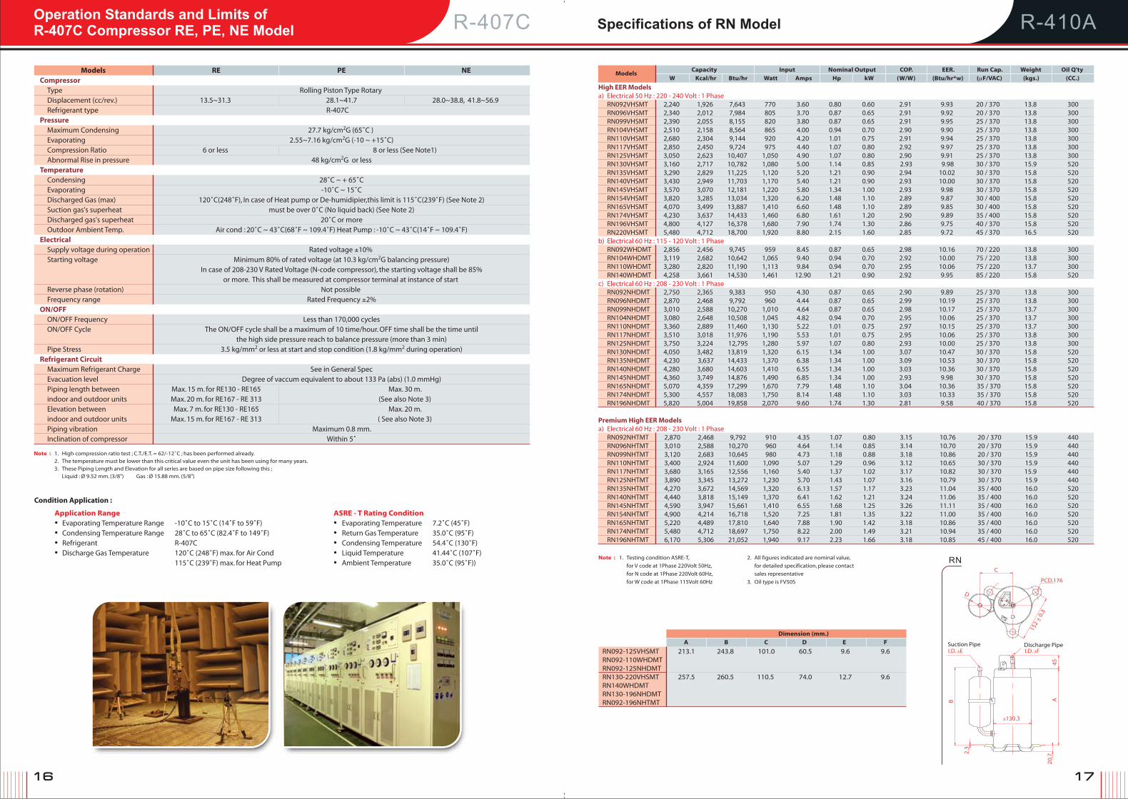
Specifications of RN ModelR-407COperation Standards and Limits ofR-407C Compressor RE, PE, NE Model R-410A
Note : 1. High compression ratio test ; C.T./E.T. = 62/-12˚C ; has been performed already. 2. The temperature must be lower than this critical value even the unit has been using for many years. 3. These Piping Length and Elevation for all series are based on pipe size following this ; Liquid : Ø 9.52 mm. (3/8") Gas : Ø 15.88 mm. (5/8")
Condition Application :
Application Range ASRE - T Rating Condition • Evaporating Temperature Range -10˚C to 15˚C (14˚F to 59˚F) • Evaporating Temperature 7.2˚C (45˚F) • Condensing Temperature Range 28˚C to 65˚C (82.4˚F to 149˚F) • Return Gas Temperature 35.0˚C (95˚F) • Refrigerant R-407C • Condensing Temperature 54.4˚C (130˚F) • Discharge Gas Temperature 120˚C (248˚F) max. for Air Cond • Liquid Temperature 41.44˚C (107˚F) 115˚C (239˚F) max. for Heat Pump • Ambient Temperature 35.0˚C (95˚F))
Models RE PE NECompressor Type Rolling Piston Type Rotary Displacement (cc/rev.) 13.5~31.3 28.1~41.7 28.0~38.8, 41.8~56.9 Refrigerant type R-407C Pressure Maximum Condensing 27.7 kg/cm2G (65˚C ) Evaporating 2.55~7.16 kg/cm2G (-10 ~ +15˚C) Compression Ratio 6 or less 8 or less (See Note1) Abnormal Rise in pressure 48 kg/cm2G or lessTemperature Condensing 28˚C ~ + 65˚C Evaporating -10˚C ~ 15˚C Discharged Gas (max) 120˚C(248˚F), In case of Heat pump or De-humidipier,this limit is 115˚C(239˚F) (See Note 2) Suction gas's superheat must be over 0˚C (No liquid back) (See Note 2) Discharged gas's superheat 20˚C or more Outdoor Ambient Temp. Air cond : 20˚C ~ 43˚C(68˚F ~ 109.4˚F) Heat Pump : -10˚C ~ 43˚C(14˚F ~ 109.4˚F)Electrical Supply voltage during operation Rated voltage ±10% Starting voltage Minimum 80% of rated voltage (at 10.3 kg/cm2G balancing pressure) In case of 208-230 V Rated Voltage (N-code compressor), the starting voltage shall be 85% or more. This shall be measured at compressor terminal at instance of start Reverse phase (rotation) Not possible Frequency range Rated Frequency ±2%ON/OFF ON/OFF Frequency Less than 170,000 cycles ON/OFF Cycle The ON/OFF cycle shall be a maximum of 10 time/hour. OFF time shall be the time until the high side pressure reach to balance pressure (more than 3 min) Pipe Stress 3.5 kg/mm2 or less at start and stop condition (1.8 kg/mm2 during operation)Refrigerant Circuit Maximum Refrigerant Charge See in General Spec Evacuation level Degree of vaccum equivalent to about 133 Pa (abs) (1.0 mmHg) Piping length between Max. 15 m. for RE130 - RE165 Max. 30 m. indoor and outdoor units Max. 20 m. for RE167 - RE 313 (See also Note 3) Elevation between Max. 7 m. for RE130 - RE165 Max. 20 m. indoor and outdoor units Max. 15 m. for RE167 - RE 313 ( See also Note 3) Piping vibration Maximum 0.8 mm. Inclination of compressor Within 5˚
Models
Capacity Input Nominal Output COP. EER. Run Cap. Weight Oil Q'ty
W Kcal/hr Btu/hr Watt Amps Hp kW (W/W) (Btu/hr*w) (μF/VAC) (kgs.) (CC.)
High EER Models a) Electrical 50 Hz : 220 - 240 Volt : 1 Phase RN092VHSMT 2,240 1,926 7,643 770 3.60 0.80 0.60 2.91 9.93 20 / 370 13.8 300 RN096VHSMT 2,340 2,012 7,984 805 3.70 0.87 0.65 2.91 9.92 20 / 370 13.8 300 RN099VHSMT 2,390 2,055 8,155 820 3.80 0.87 0.65 2.91 9.95 25 / 370 13.8 300 RN104VHSMT 2,510 2,158 8,564 865 4.00 0.94 0.70 2.90 9.90 25 / 370 13.8 300 RN110VHSMT 2,680 2,304 9,144 920 4.20 1.01 0.75 2.91 9.94 25 / 370 13.8 300 RN117VHSMT 2,850 2,450 9,724 975 4.40 1.07 0.80 2.92 9.97 25 / 370 13.8 300 RN125VHSMT 3,050 2,623 10,407 1,050 4.90 1.07 0.80 2.90 9.91 25 / 370 13.8 300 RN130VHSMT 3,160 2,717 10,782 1,080 5.00 1.14 0.85 2.93 9.98 30 / 370 15.9 520 RN135VHSMT 3,290 2,829 11,225 1,120 5.20 1.21 0.90 2.94 10.02 30 / 370 15.8 520 RN140VHSMT 3,430 2,949 11,703 1,170 5.40 1.21 0.90 2.93 10.00 30 / 370 15.8 520 RN145VHSMT 3,570 3,070 12,181 1,220 5.80 1.34 1.00 2.93 9.98 30 / 370 15.8 520 RN154VHSMT 3,820 3,285 13,034 1,320 6.20 1.48 1.10 2.89 9.87 30 / 400 15.8 520 RN165VHSMT 4,070 3,499 13,887 1,410 6.60 1.48 1.10 2.89 9.85 30 / 400 15.8 520 RN174VHSMT 4,230 3,637 14,433 1,460 6.80 1.61 1.20 2.90 9.89 35 / 400 15.8 520 RN196VHSMT 4,800 4,127 16,378 1,680 7.90 1.74 1.30 2.86 9.75 40 / 370 15.8 520 RN220VHSMT 5,480 4,712 18,700 1,920 8.80 2.15 1.60 2.85 9.72 45 / 370 16.5 520b) Electrical 60 Hz : 115 - 120 Volt : 1 Phase RN092WHDMT 2,856 2,456 9,745 959 8.45 0.87 0.65 2.98 10.16 70 / 220 13.8 300 RN104WHDMT 3,119 2,682 10,642 1,065 9.40 0.94 0.70 2.92 10.00 75 / 220 13.8 300 RN110WHDMT 3,280 2,820 11,190 1,113 9.84 0.94 0.70 2.95 10.06 75 / 220 13.7 300 RN140WHDMT 4,258 3,661 14,530 1,461 12.90 1.21 0.90 2.92 9.95 85 / 220 15.8 520c) Electrical 60 Hz : 208 - 230 Volt : 1 Phase RN092NHDMT 2,750 2,365 9,383 950 4.30 0.87 0.65 2.90 9.89 25 / 370 13.8 300 RN096NHDMT 2,870 2,468 9,792 960 4.44 0.87 0.65 2.99 10.19 25 / 370 13.8 300 RN099NHDMT 3,010 2,588 10,270 1,010 4.64 0.87 0.65 2.98 10.17 25 / 370 13.7 300 RN104NHDMT 3,080 2,648 10,508 1,045 4.82 0.94 0.70 2.95 10.06 25 / 370 13.7 300 RN110NHDMT 3,360 2,889 11,460 1,130 5.22 1.01 0.75 2.97 10.15 25 / 370 13.7 300 RN117NHDMT 3,510 3,018 11,976 1,190 5.53 1.01 0.75 2.95 10.06 25 / 370 13.8 300 RN125NHDMT 3,750 3,224 12,795 1,280 5.97 1.07 0.80 2.93 10.00 25 / 370 13.8 300 RN130NHDMT 4,050 3,482 13,819 1,320 6.15 1.34 1.00 3.07 10.47 30 / 370 15.8 520 RN135NHDMT 4,230 3,637 14,433 1,370 6.38 1.34 1.00 3.09 10.53 30 / 370 15.8 520 RN140NHDMT 4,280 3,680 14,603 1,410 6.55 1.34 1.00 3.03 10.36 30 / 370 15.8 520 RN145NHDMT 4,360 3,749 14,876 1,490 6.85 1.34 1.00 2.93 9.98 30 / 370 15.8 520 RN165NHDMT 5,070 4,359 17,299 1,670 7.79 1.48 1.10 3.04 10.36 35 / 370 15.8 520 RN174NHDMT 5,300 4,557 18,083 1,750 8.14 1.48 1.10 3.03 10.33 35 / 370 15.8 520 RN196NHDMT 5,820 5,004 19,858 2,070 9.60 1.74 1.30 2.81 9.58 40 / 370 15.8 520
Premium High EER Models a) Electrical 60 Hz : 208 - 230 Volt : 1 Phase RN092NHTMT 2,870 2,468 9,792 910 4.35 1.07 0.80 3.15 10.76 20 / 370 15.9 440 RN096NHTMT 3,010 2,588 10,270 960 4.64 1.14 0.85 3.14 10.70 20 / 370 15.9 440 RN099NHTMT 3,120 2,683 10,645 980 4.73 1.18 0.88 3.18 10.86 20 / 370 15.9 440 RN110NHTMT 3,400 2,924 11,600 1,090 5.07 1.29 0.96 3.12 10.65 30 / 370 15.9 440 RN117NHTMT 3,680 3,165 12,556 1,160 5.40 1.37 1.02 3.17 10.82 30 / 370 15.9 440 RN125NHTMT 3,890 3,345 13,272 1,230 5.70 1.43 1.07 3.16 10.79 30 / 370 15.9 440 RN135NHTMT 4,270 3,672 14,569 1,320 6.13 1.57 1.17 3.23 11.04 35 / 400 16.0 520 RN140NHTMT 4,440 3,818 15,149 1,370 6.41 1.62 1.21 3.24 11.06 35 / 400 16.0 520 RN145NHTMT 4,590 3,947 15,661 1,410 6.55 1.68 1.25 3.26 11.11 35 / 400 16.0 520 RN154NHTMT 4,900 4,214 16,718 1,520 7.25 1.81 1.35 3.22 11.00 35 / 400 16.0 520 RN165NHTMT 5,220 4,489 17,810 1,640 7.88 1.90 1.42 3.18 10.86 35 / 400 16.0 520 RN174NHTMT 5,480 4,712 18,697 1,750 8.22 2.00 1.49 3.21 10.94 35 / 400 16.0 520 RN196NHTMT 6,170 5,306 21,052 1,940 9.17 2.23 1.66 3.18 10.85 45 / 400 16.0 520
Note : 1. Testing condition ASRE-T,
for V code at 1Phase 220Volt 50Hz,
for N code at 1Phase 220Volt 60Hz,
for W code at 1Phase 115Volt 60Hz
2. All figures indicated are nominal value,
for detailed specification, please contact
sales representative
3. Oil type is FV50S
RN
RN092-125VHSMT 213.1 243.8 101.0 60.5 9.6 9.6 RN092-110WHDMT RN092-125NHDMT RN130-220VHSMT 257.5 260.5 110.5 74.0 12.7 9.6 RN140WHDMT RN130-196NHDMT RN092-196NHTMT
Dimension (mm.)
A B C D E F
C
PCD.176
D
152
+ 0.
3_
I.D. ΔFDischarge Pipe
I.D. ΔESuction Pipe
45
B A
Δ130.3
2.3
20.7
18 19
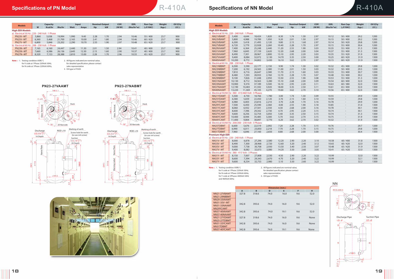
R-410A R-410ASpecifications of PN Model Specifications of NN Model
Models
Capacity Input Nominal Output COP. EER. Run Cap. Weight Oil Q'ty
W Kcal/hr Btu/hr Watt Amps Hp kW (W/W) (Btu/hr*w) (μF/VAC) (kgs.) (CC.)
High EER Models a) Electrical 50 Hz : 220 - 240 Volt : 1 Phase NN21VBAMT 5,400 4,644 18,424 1,820 8.30 1.74 1.30 2.97 10.12 50 / 400 29.2 1200 NN23VBAMT 5,800 4,988 19,789 1,950 9.20 2.01 1.50 2.97 10.15 50 / 400 29.2 1200 NN25VBAMT 6,300 5,418 21,495 2,120 9.80 2.15 1.60 2.97 10.14 50 / 420 29.8 1200 NN27VBAMT 6,720 5,779 22,928 2,260 10.40 2.28 1.70 2.97 10.15 55 / 400 30.4 1200 NN29VAAMT 7,400 6,364 25,248 2,440 11.20 2.55 1.90 3.03 10.35 55 / 400 31.3 1300 NN31VAAMT 7,960 6,845 27,159 2,620 12.20 2.68 2.00 3.04 10.37 55 / 400 31.3 1300 NN33VAAMT 8,490 7,301 28,967 2,800 13.10 2.95 2.20 3.03 10.35 55 / 420 31.9 1300 NN37VAAMT 9,400 8,084 32,072 3,130 14.70 3.35 2.50 3.00 10.25 60 / 420 31.9 1300 NN40VAAMT 10,200 8,772 34,802 3,430 16.10 3.62 2.70 2.97 10.15 60 / 420 31.9 1300b) Electrical 60 Hz : 208 - 230 Volt : 1 Phase NN21NBBMT 6,500 5,590 22,177 2,150 9.90 1.74 1.30 3.02 10.32 45 / 400 29.8 1200 NN23NBBMT 7,200 6,192 24,565 2,380 11.00 2.01 1.50 3.03 10.32 50 / 400 29.5 1200 NN25NBBMT 7,810 6,716 26,647 2,580 11.70 2.15 1.60 3.03 10.33 55 / 400 30.7 1200 NN27NBBMT 8,480 7,293 28,933 2,760 12.70 2.28 1.70 3.07 10.48 55 / 400 30.2 1200 NN29NBBMT 9,100 7,826 31,048 2,950 13.50 2.55 1.90 3.08 10.53 55 / 400 31.3 1200 NN31NAAMT 10,130 8,712 34,563 3,280 15.10 2.68 2.00 3.09 10.54 60 / 400 32.0 1300 NN33NAAMT 10,900 9,374 37,189 3,500 16.10 2.95 2.20 3.11 10.63 60 / 380 32.0 1300 NN37NAAMT 12,190 10,483 41,592 3,920 18.00 3.35 2.50 3.11 10.61 65 / 400 32.0 1300 NN40NAAMT 13,220 11,369 45,105 4,270 19.60 3.62 2.70 3.10 10.56 65 / 400 32.0 1300c) Electrical 50/60 Hz : 380 - 415/460 Volt : 3 Phases NN21YDAMT 5,500 4,730 18,766 1,780 3.00 1.74 1.30 3.09 10.55 - 29.9 1200 NN25YDAMT 6,580 5,659 22,450 2,120 3.70 2.15 1.60 3.10 10.59 - 29.8 1200 NN27YDAMT 6,980 6,003 23,816 2,210 3.70 2.28 1.70 3.16 10.78 - 29.9 1200 NN29YCAMT 7,500 6,450 25,590 2,360 4.00 2.55 1.90 3.18 10.85 - 31.0 1300 NN31YCAMT 8,060 6,932 27,501 2,550 4.30 2.68 2.00 3.16 10.78 - 30.1 1300 NN33YCAMT 8,600 7,396 29,342 2,730 4.70 2.95 2.20 3.15 10.74 - 30.1 1300 NN37YCAMT 9,600 8,256 32,754 3,050 5.40 3.35 2.50 3.15 10.74 - 31.3 1300 NN40YCAMT 10,400 8,944 35,485 3,300 5.70 3.62 2.70 3.15 10.75 - 31.9 1300 NN44YCAMT 11,400 9,804 38,897 3,770 6.20 3.62 2.70 3.02 10.32 - 31.9 1300d) Electrical 50/60 Hz : 200/200 - 230 Volt : 3 Phases NN25TDBMT 6,600 5,676 22,519 2,092 7.20 2.28 1.70 3.15 10.76 - 29.7 1200 NN27TDBMT 6,990 6,011 23,850 2,218 7.70 2.28 1.70 3.15 10.75 - 29.8 1200 NN31TDBMT 7,960 6,846 27,160 2,650 8.80 2.68 2.00 3.00 10.25 - 30.4 1300Premium High EER a) Electrical 50 Hz : 220 - 240 Volt : 1 Phase NN31V--MT 8,000 6,878 27,296 2,580 12.20 2.90 2.20 3.10 10.58 60 / 400 31.8 1300 NN33V--MT 8,490 7,300 28,968 2,720 12.60 3.20 2.40 3.12 10.65 60 / 420 32.0 1300 NN35V--MT 9,000 7,738 30,708 2,930 13.50 3.40 2.50 3.07 10.48 65 / 420 31.9 1300 NN37V--MT 9,400 8,082 32,073 3,080 14.20 3.50 2.60 3.05 10.41 65 / 420 32.0 1300b) Electrical 50/60 Hz : 380 - 415 Volt : 3 Phases NN31Y--MT 8,150 7,007 27,808 2,530 4.50 2.90 2.20 3.22 10.99 - 32.0 1300 NN33Y--MT 8,600 7,394 29,343 2,670 4.70 3.20 2.40 3.22 10.99 - 32.1 1300 NN37Y--MT 9,600 8,254 32,755 2,980 5.10 3.50 2.60 3.22 10.99 - 32.2 1300
Note : 1. Testing condition ASRE-T,
for V code at 1Phase 220Volt 50Hz,
for N code at 1Phase 220Volt 60Hz,
2. All figures indicated are nominal value,
for detailed specification, please contact
sales representative
3. Oil type is FV50S
Note : 1. Testing condition ASRE-T,
for V code at 1Phase 220Volt 50Hz,
for N code at 1Phase 220Volt 60Hz,
for Y code at 3Phases 400Volt 50Hz
and 460Volt 60Hz.
2. All figures indicated are nominal value,
for detailed specification, please contact
sales representative
3. Oil type is FV50S
NN21-27VBAMT 327.8 318.6 74.0 16.0 9.6 52.0 NN21-29NBBMT NN29-33VAAMT NN31-35V--MT 342.8 393.6 74.0 16.0 9.6 52.0 NN31-33NAAMT NN29YCAMT NN37-40VAAMT 342.8 393.6 74.0 19.1 9.6 52.0 NN37-40NAAMT NN21-27YDAMT 327.8 318.6 74.0 16.0 9.6 None NN25-27TDBMT NN31-33YCAMT 342.8 393.6 74.0 16.0 9.6 None NN31TDBMT NN37-40YCAMT 342.8 393.6 74.0 19.1 9.6 None
Dimension (mm.)
A B D E F H
NN
118.8
D
148
+ 1
_
(24˚
)
PCD.209.3
52.9
I.D. ΔF
Discharge PipeI.D. ΔE
Suction Pipe
BA
Δ168.5
23.7
+ 1
_ 2.3
H
Models
Capacity Input Nominal Output COP. EER. Run Cap. Weight Oil Q'ty
W Kcal/hr Btu/hr Watt Amps Hp kW (W/W) (Btu/hr*w) (μF/VAC) (kgs.) (CC.)
High EER Models a) Electrical 50 Hz : 220 - 240 Volt : 1 Phase PN23V--MT 5,860 5,038 19,994 1,990 9.40 2.28 1.70 2.94 10.46 55 / 400 23.7 900 PN25V--MT 6,360 5,468 21,700 2,165 10.00 2.41 1.80 2.94 10.46 60 / 420 23.7 900 PN27V--MT 6,800 5,846 23,202 2,290 10.70 2.55 1.90 2.97 10.48 65 / 420 23.7 900b) Electrical 60 Hz : 208 - 230 Volt : 1 Phase PN23N--MT 7,165 6,160 24,447 2,440 11.30 2.01 1.50 2.94 10.41 40 / 400 23.7 900 PN25N--MT 7,660 6,586 26,136 2,645 12.30 2.15 1.60 2.90 10.37 40 / 400 23.7 900 PN27N--MT 8,320 7,153 28,388 2,810 13.00 2.28 1.70 2.96 10.55 45 / 420 23.7 900
(I.D.Δ9.6+0.2) 0
(I.D.Δ16+0.25) 0
(I.D.Δ9.6+0.2) 0
(I.D.Δ16+0.25) 0
148 + 1_
148
+ 1
_
148
+ 1
_
23.7
+ 1
_
23.7
+ 1
_
PN23-27NABMT
Hock
R22.34 - 23
20 Depth20 Depth
16 Depth 16 Depth
War
nin
g L
abel
Nam
e P
late
PN23-27VAAMT
5.7
45
57 57
111.3
148 + 1_
5.7 111.3
Hock
Δ147.2 Δ147.2
(22
o ) 45
(22
o )
30 o 30 o
32.2
32.2
R22.3
Gla
ss T
erm
inal
Gla
ss T
erm
inal
4 -Δ23
ROD Δ10
Δ78Δ74
Δ78Δ74
2D Barcode 2D Barcode
Marking of earth
Screw hole for earth(to use m4 screw)
Suction
Discharge ROD Δ10Marking of earth
Screw hole for earth(to use m4 screw)
Suction
Discharge
58.9
2.3
58.9
2.3
308.
9191
32
308.
9191
32
3252(3
41)
317.
6
3252(3
41)
317.
6
Nam
e P
late
20 21
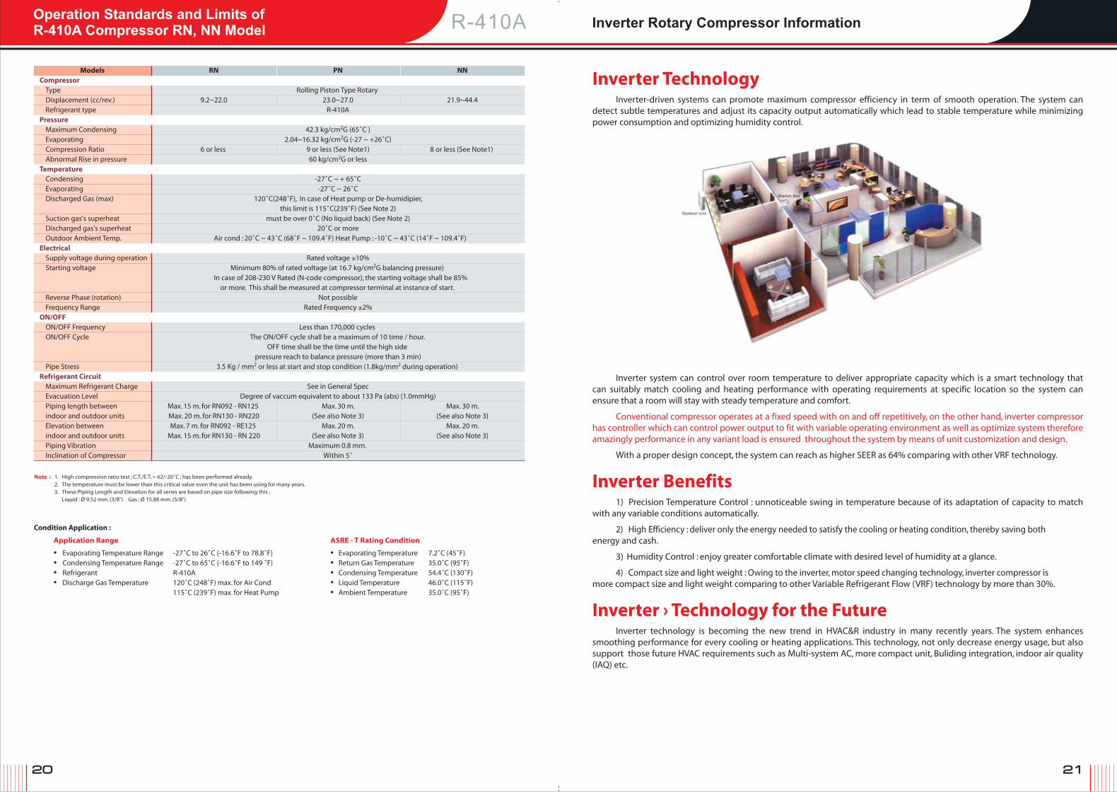
Operation Standards and Limits ofR-410A Compressor RN, NN Model Inverter Rotary Compressor Information
Models RN PN NN Compressor Type Rolling Piston Type Rotary Displacement (cc/rev.) 9.2~22.0 23.0~27.0 21.9~44.4 Refrigerant type R-410APressure Maximum Condensing 42.3 kg/cm2G (65˚C ) Evaporating 2.04~16.32 kg/cm2G (-27 ~ +26˚C) Compression Ratio 6 or less 9 or less (See Note1) 8 or less (See Note1) Abnormal Rise in pressure 60 kg/cm2G or lessTemperature Condensing -27˚C ~ + 65˚C Evaporating -27˚C ~ 26˚C Discharged Gas (max) 120˚C(248˚F), In case of Heat pump or De-humidipier, this limit is 115˚C(239˚F) (See Note 2) Suction gas's superheat must be over 0˚C (No liquid back) (See Note 2) Discharged gas's superheat 20˚C or more Outdoor Ambient Temp. Air cond : 20˚C ~ 43˚C (68˚F ~ 109.4˚F) Heat Pump : -10˚C ~ 43˚C (14˚F ~ 109.4˚F)Electrical Supply voltage during operation Rated voltage ±10% Starting voltage Minimum 80% of rated voltage (at 16.7 kg/cm2G balancing pressure) In case of 208-230 V Rated (N-code compressor), the starting voltage shall be 85% or more. This shall be measured at compressor terminal at instance of start. Reverse Phase (rotation) Not possible Frequency Range Rated Frequency ±2%ON/OFF ON/OFF Frequency Less than 170,000 cycles ON/OFF Cycle The ON/OFF cycle shall be a maximum of 10 time / hour. OFF time shall be the time until the high side pressure reach to balance pressure (more than 3 min) Pipe Stress 3.5 Kg / mm2 or less at start and stop condition (1.8kg/mm2 during operation) Refrigerant Circuit Maximum Refrigerant Charge See in General Spec Evacuation Level Degree of vaccum equivalent to about 133 Pa (abs) (1.0mmHg) Piping length between Max. 15 m. for RN092 - RN125 Max. 30 m. Max. 30 m. indoor and outdoor units Max. 20 m. for RN130 - RN220 (See also Note 3) (See also Note 3) Elevation between Max. 7 m. for RN092 - RE125 Max. 20 m. Max. 20 m. indoor and outdoor units Max. 15 m. for RN130 - RN 220 (See also Note 3) (See also Note 3) Piping Vibration Maximum 0.8 mm. Inclination of Compressor Within 5˚
Note : 1. High compression ratio test ; C.T./E.T. = 62/-20˚C ; has been performed already. 2. The temperature must be lower than this critical value even the unit has been using for many years. 3. These Piping Length and Elevation for all series are based on pipe size following this ; Liquid : Ø 9.52 mm. (3/8") Gas : Ø 15.88 mm. (5/8")
Condition Application :
Application Range ASRE - T Rating Condition
• Evaporating Temperature Range -27˚C to 26˚C (-16.6˚F to 78.8˚F) • Evaporating Temperature 7.2˚C (45˚F) • Condensing Temperature Range -27˚C to 65˚C (-16.6˚F to 149 ˚F) • Return Gas Temperature 35.0˚C (95˚F) • Refrigerant R-410A • Condensing Temperature 54.4˚C (130˚F) • Discharge Gas Temperature 120˚C (248˚F) max. for Air Cond • Liquid Temperature 46.0˚C (115˚F) 115˚C (239˚F) max. for Heat Pump • Ambient Temperature 35.0˚C (95˚F)
Inverter Technology Inverter-driven systems can promote maximum compressor efficiency in term of smooth operation. The system can
detect subtle temperatures and adjust its capacity output automatically which lead to stable temperature while minimizing power consumption and optimizing humidity control.
Inverter system can control over room temperature to deliver appropriate capacity which is a smart technology that can suitably match cooling and heating performance with operating requirements at specific location so the system can ensure that a room will stay with steady temperature and comfort.
Conventional compressor operates at a fixed speed with on and off repetitively, on the other hand, inverter compressor has controller which can control power output to fit with variable operating environment as well as optimize system therefore amazingly performance in any variant load is ensured throughout the system by means of unit customization and design.
With a proper design concept, the system can reach as higher SEER as 64% comparing with other VRF technology.
Inverter Benefits
1) Precision Temperature Control : unnoticeable swing in temperature because of its adaptation of capacity to match with any variable conditions automatically.
2) High Efficiency : deliver only the energy needed to satisfy the cooling or heating condition, thereby saving both energy and cash.
3) Humidity Control : enjoy greater comfortable climate with desired level of humidity at a glance.
4) Compact size and light weight : Owing to the inverter, motor speed changing technology, inverter compressor is more compact size and light weight comparing to other Variable Refrigerant Flow (VRF) technology by more than 30%.
Inverter › Technology for the Future
Inverter technology is becoming the new trend in HVAC&R industry in many recently years. The system enhances smoothing performance for every cooling or heating applications. This technology, not only decrease energy usage, but also support those future HVAC requirements such as Multi-system AC, more compact unit, Buliding integration, indoor air quality (IAQ) etc.
R-410A

22
Specifications of TNB Model
Twin Rotary InverterTwin rotary inverter synergize two significant advantages as a combination between highly powerful and smooth
performance through the latest innovative solution of 'Twin Mechanism'. This mechanism are done by balancing torque of two compression chambers in a revolution which can operate at the highest efficiency with extremely low vibration and low noise. Moreover, they are compact sizes, lightweight, and wider range of operating area than other rotary compressor. With our inverter design technic, we use selective raw material and meticulous process to ensure superior performance and reliability.
Our DC Inverter Twin Rotary, advanced technology is the combination of double technology solution which are 'Twin Mechanism' and 'Inverter Technology'. This unique solution can ensure specifically for the highest smooth performance with quiet compressor operation and high energy saving when compare with other compressor. Its compact sizes and lightweight are also comfortable for unit with space limitation but need for high capacity.
The Special Features of Twin Rotary Inverter Compressor 1. High efficiency (E.E.R. 11.06 with R-410A) High efficiency resulting from twin mechanism, DC inverter technology
and selective motor component is embedded into every single Twin Rotary Inverter Compressor to ensure the best performance.
2. High reliability As a result of using high-grade raw materials such as specialized permanent magnet, Rare Earth Magnet, which is more durable to demagnetize thereby our twin rotary is very reliable to operate in high frequency inverter supply. Higher operating freqency ability brings about a more wider capacity range.
3. Extremely Low Noise & Vibration Twin Rotary Inverter Compressor uses the special crankshaft. Its balanced geometry create smooth operation and silent as you never feel.
4. Compact size & Light weight With the advanced technology, the weight is obviously reduced by 50%. So the size of overall system will be more compact.
a) DC Inverter SNB130FGBMT 510-9,670 440-8,310 1,740-33,000 3,630 12,386 1,140 5.4 3.18 10.86 7.9 350 SNB172FEKMT 970-13,760 830-11,830 3,310-46,950 4,830 16,480 1,560 6.7 3.10 10.56 8.6 400 TNB220FLHMT 990-16,100 850-13,840 3,370-54,930 7,130 24,328 2,200 9.7 3.24 11.06 14.0 870 TNB306FPGMT 1,500-22,100 1,290-19,000 5,110-75,400 9,880 33,711 3,010 13.5 3.28 11.2 16 870
Models
Capacity Range Performance at 60 rps Weight Oil Q'ty
(min~max) Capacity Input COP. EER.
Watt Kcal/hr Btu/hr W BTU/hr Watt Amps (W/W) (Btu/hr*w) (kgs.) (CC.)
Note : Oil type is FV50S
R-410A
Δ129.6
Discharge PipeSuction Pipe
32 45
273
(I.D. Δ9.52 0 ) +0.2(I.D. Δ16 0 ) +0.2
(30)
(DIS
)
Scre
w H
ole
for
Eart
h(T
o u
se M
4 sc
reen
)
Mak
rin
g o
f ear
th
Nam
e P
late
206.
87.
0
2.3
20.7
35.5
28
234.
8
3- Δ20
152
+ 0
.3_
110.5 + 2_ Terminal Cover
(R88)
Holder
(Sam
e Pi
tche
s)
R20
Δ74
Δ78
R38
(same Pitches)
2D Barcode
Terminal Cover
3 - Δ20
93 + 2
Δ112.2
20.5
o
Δ64.5
Δ60.
5
R 38
RODDischarge Pipe (I.D.Δ12+0.2) 0
(I.D.Δ8+0.15) 0
Suction Pipe
43
31.8
33.6
(167
)
290.
7
Nam
e P
late
211.
1
235.
1
2.3 10
49.1
2318
_
116 + 0.3 _
TNBSNB