Embed Size (px)
Citation preview
Prof. Dr.-Ing. habil. Lothar LitzInstitute of Automatic ControlUniversity of Kaiserslautern
Ambient Intelligence (AmI) Research in Kaiserslautern
Brasília, March 23, 2007
PAUL
Assisted Training Assisted Working Assisted Liv ing
2
Outline
• Introduction
• Ambient Intelligence Definition
• Kaiserslautern way of AmI-Research
• Bicycle Training Demonstrator
• AmI-based Networked Control Systems
• Outlook
3
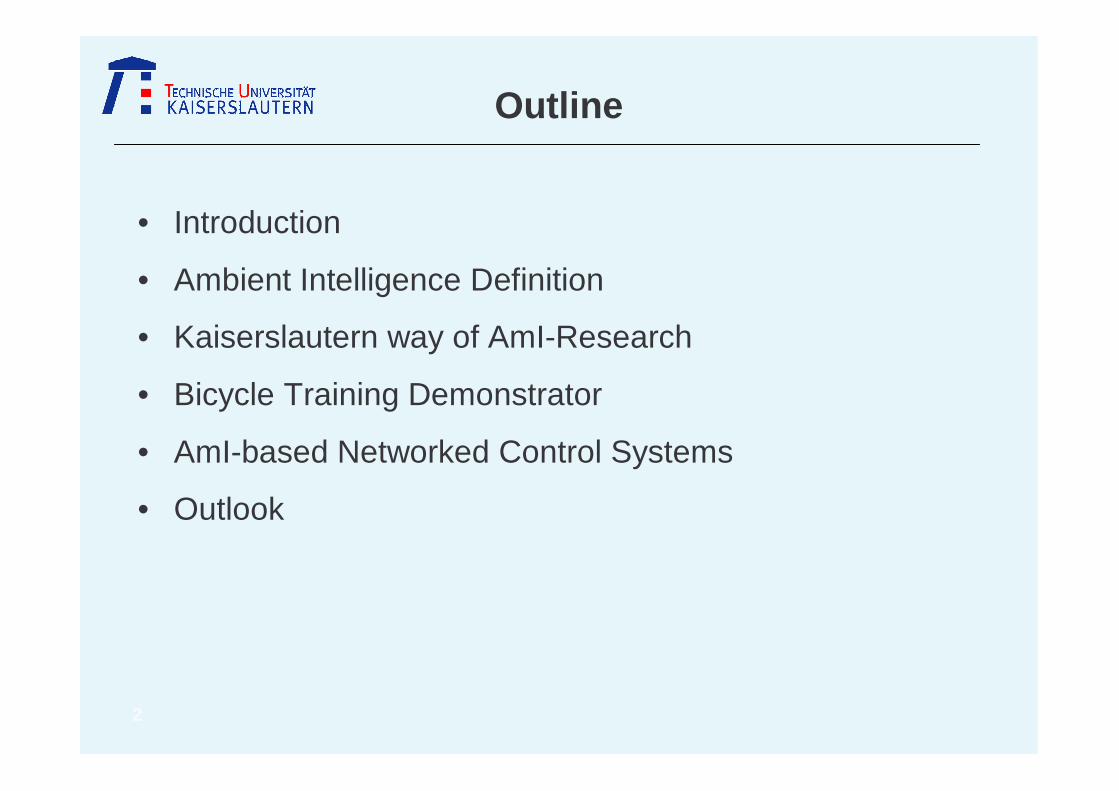
1960 70 80 90 2000 10
Mainframe0.001 computer/person
PC1
Post-PC Era>100 µµµµC/ person
Ambient
Intelligence
extensive data processing
signal processing,text processing,
multimedia, networks
scientific, commercial applications
personal applications
mobile applications
„There is no reason for any individual to have a co mputer in his home“ Ken Olsen, CEO DEC, 1977
Introduction

4
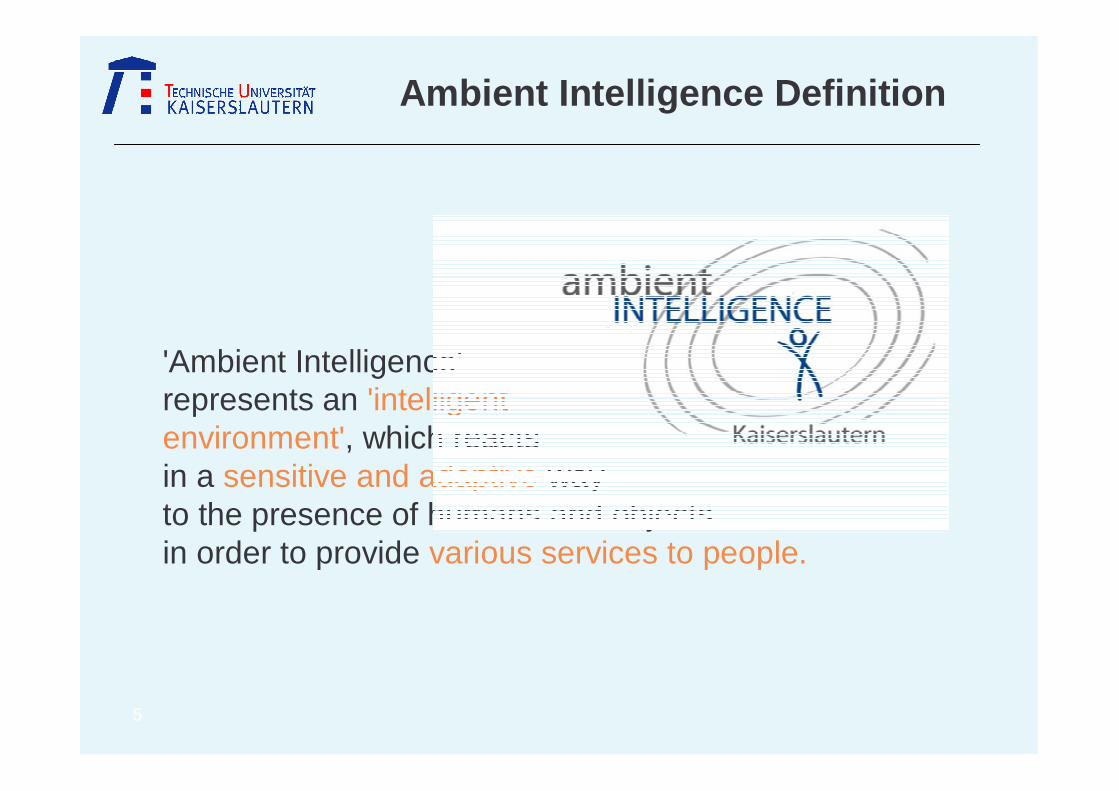
'Ambient Intelligence' represents an 'intelligent environment', which reacts in a sensitive and adaptive way to the presence of humans and objects in order to provide various services to people.
Ambient Intelligence Definition
5
'Ambient Intelligence' represents an 'intelligent environment', which reacts in a sensitive and adaptive way to the presence of humans and objects in order to provide various services to people.
Ambient Intelligence Definition
6
Ambient Intelligence Definition
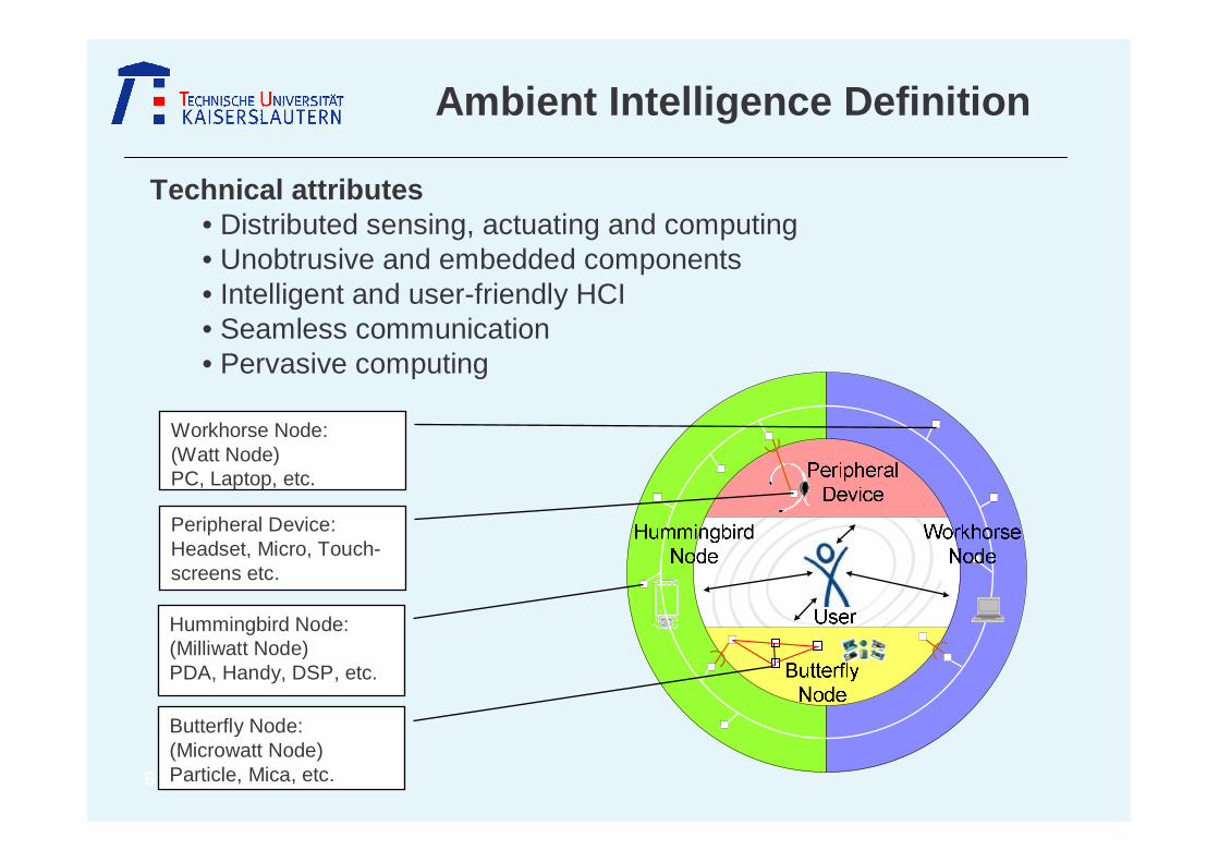
Technical attributes• Distributed sensing, actuating and computing• Unobtrusive and embedded components • Intelligent and user-friendly HCI • Seamless communication• Pervasive computing
Butterfly Node:(Microwatt Node)Particle, Mica, etc.
Hummingbird Node:(Milliwatt Node)PDA, Handy, DSP, etc.
Peripheral Device:Headset, Micro, Touch-screens etc.
Workhorse Node:(Watt Node) PC, Laptop, etc.

7
Disciplines involved
human computer interaction
communications
microelectronics / sensors
software engineering
cognition science
automatic control
relevancefor
“Am
bient“
rele
vanc
efo
r“I
ntel
ligen
ce“
Ambient Intelligence Definition
8
Kaiserslautern way of AmI-Research
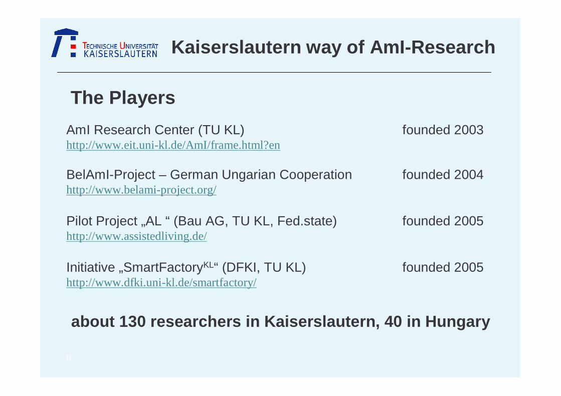
AmI Research Center (TU KL) founded 2003http://www.eit.uni-kl.de/AmI/frame.html?en
BelAmI-Project – German Ungarian Cooperation founded 2004http://www.belami-project.org/
Pilot Project „AL “ (Bau AG, TU KL, Fed.state) founded 2005http://www.assistedliving.de/
Initiative „SmartFactoryKL“ (DFKI, TU KL) founded 2005http://www.dfki.uni-kl.de/smartfactory/
The Players
about 130 researchers in Kaiserslautern, 40 in Hungar y

9
Kaiserslautern way of AmI-Research
AmI Research Center (TU KL) founded 2003http://www.eit.uni-kl.de/AmI/frame.html?en
BelAmI-Project – German Ungarian Cooperation founded 2004http://www.belami-project.org/
Pilot Project „AL “ (Bau AG, TU KL, Fed.state) founded 2005http://www.assistedliving.de/
Initiative „SmartFactoryKL“ (DFKI, TU KL) founded 2005http://www.dfki.uni-kl.de/smartfactory/
The Players
about 130 researchers in Kaiserslautern, 40 in Hungar y
10
Kaiserslautern way of AmI-Research
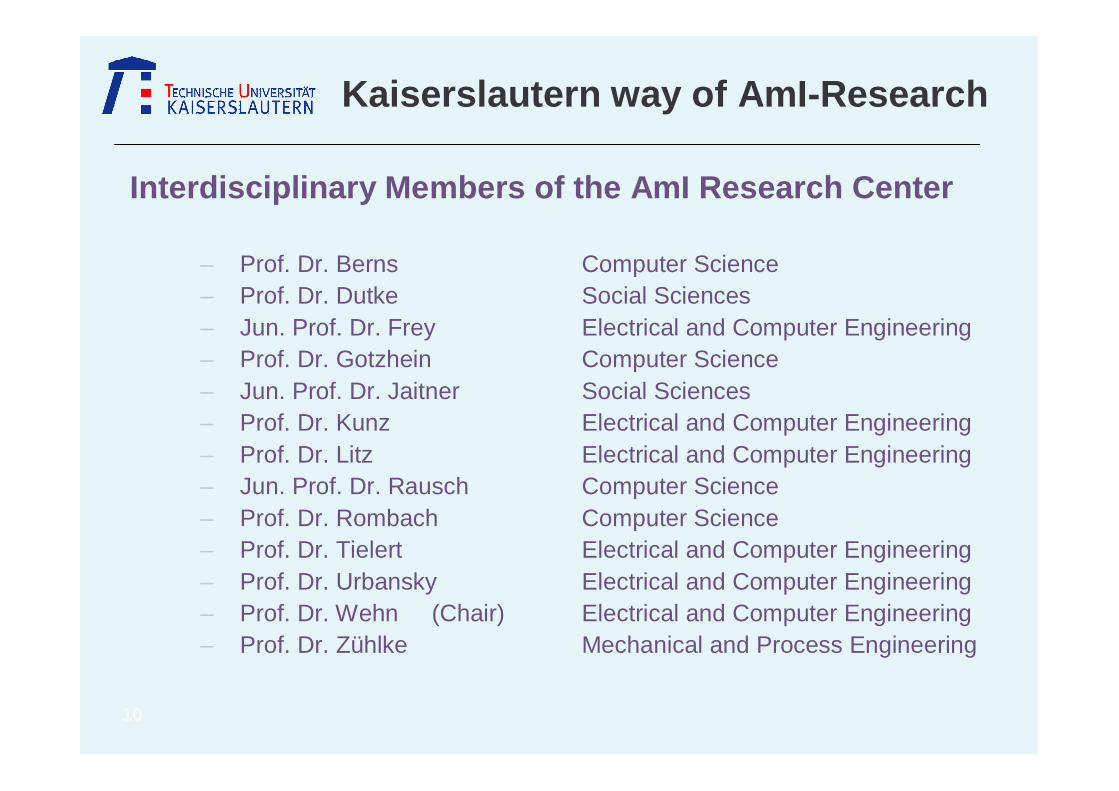
Interdisciplinary Members of the AmI Research Center
– Prof. Dr. Berns Computer Science– Prof. Dr. Dutke Social Sciences– Jun. Prof. Dr. Frey Electrical and Computer Engineering– Prof. Dr. Gotzhein Computer Science– Jun. Prof. Dr. Jaitner Social Sciences– Prof. Dr. Kunz Electrical and Computer Engineering– Prof. Dr. Litz Electrical and Computer Engineering– Jun. Prof. Dr. Rausch Computer Science– Prof. Dr. Rombach Computer Science– Prof. Dr. Tielert Electrical and Computer Engineering– Prof. Dr. Urbansky Electrical and Computer Engineering– Prof. Dr. Wehn (Chair) Electrical and Computer Engineering– Prof. Dr. Zühlke Mechanical and Process Engineering
11
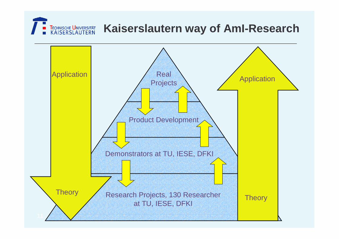
Kaiserslautern way of AmI-Research
Research Projects, 130 Researcherat TU, IESE, DFKI
Product Development
Demonstrators at TU, IESE, DFKI
RealProjects
Theory
ApplicationApplication
Theory
12
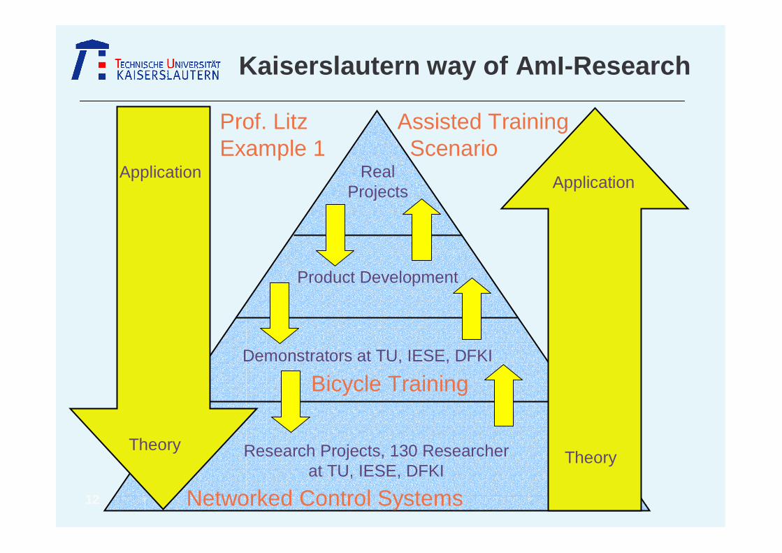
Kaiserslautern way of AmI-Research
Product Development
RealProjects
Theory
ApplicationApplication
Theory
Prof. LitzExample 1
Networked Control Systems
Bicycle Training
Assisted Training Scenario
Demonstrators at TU, IESE, DFKI
Research Projects, 130 Researcherat TU, IESE, DFKI

13
Product Development
RealProjects
Theory
ApplicationApplication
Theory
Kaiserslautern way of AmI-Research
Prof. LitzExample 2
Home Sensor Data Mining, HCI
Elderly Apartment
Assisted Living Scenario
Conference Room 476
CIBEK, Mobotix
Demonstrators at TU, IESE, DFKI
Research Projects, 130 Researcherat TU, IESE, DFKI

14
Kaiserslautern way of AmI-Research
Assisted Training Bicycle Training Assistance (TU)
Scenarios Demonstrators
Assisted Living Demonstration Apartment (IESE)Conference Room (TU)
Assisted Working Smart Factory (DFKI, TU)

15
Kaiserslautern way of AmI-Research
Assisted Training Bicycle Training Assistance (TU)
Scenarios Demonstrators
Assisted Living Demonstration Apartment (IESE)Conference Room (TU)
Assisted Working Smart Factory (DFKI, TU)
16
Bicycle Training Demonstrator
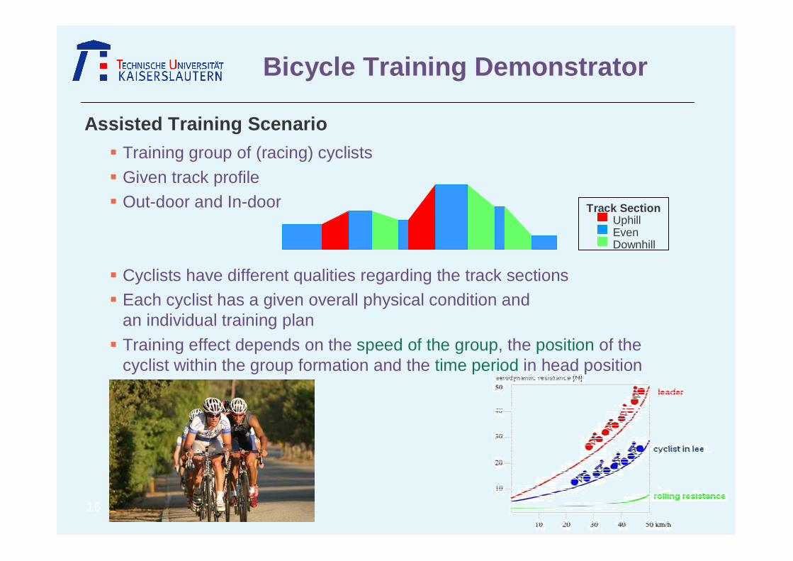
Assisted Training Scenario
� Training group of (racing) cyclists
� Given track profile� Out-door and In-door
� Cyclists have different qualities regarding the track sections� Each cyclist has a given overall physical condition and
an individual training plan
� Training effect depends on the speed of the group, the position of the cyclist within the group formation and the time period in head position
Track SectionUphillEvenDownhill

17
Bicycle Training Demonstrator
Research Topics
Common for Both
� New sensors, e.g. power pedal meter, simplified ECG
� Efficient communication (UWB) for body area networks
� Control algorithms and training strategies for In-Door, Out-Door
Bicyle Training Demonstrator
� Low power sensors, signal processing and communication
� Ad-hoc communication
Out-door In-door
� Dynamic integration of devices
� Virtual races
� Coconi tests
� Experiments to evaluate the perceptibility of different speech generation methods

18
Bicycle Training Demonstrator
• Heartbeat
• Electrocardiogram
• Speed• Cadence
• Slope
• Headwind speed
• Torques on right and left pedal
• Mechanical Power
• GPS• Borg’s scale
• Environment Simulation• Demonstrator Steering
Demonstrator Structure
19
Bicycle Training Demonstrator
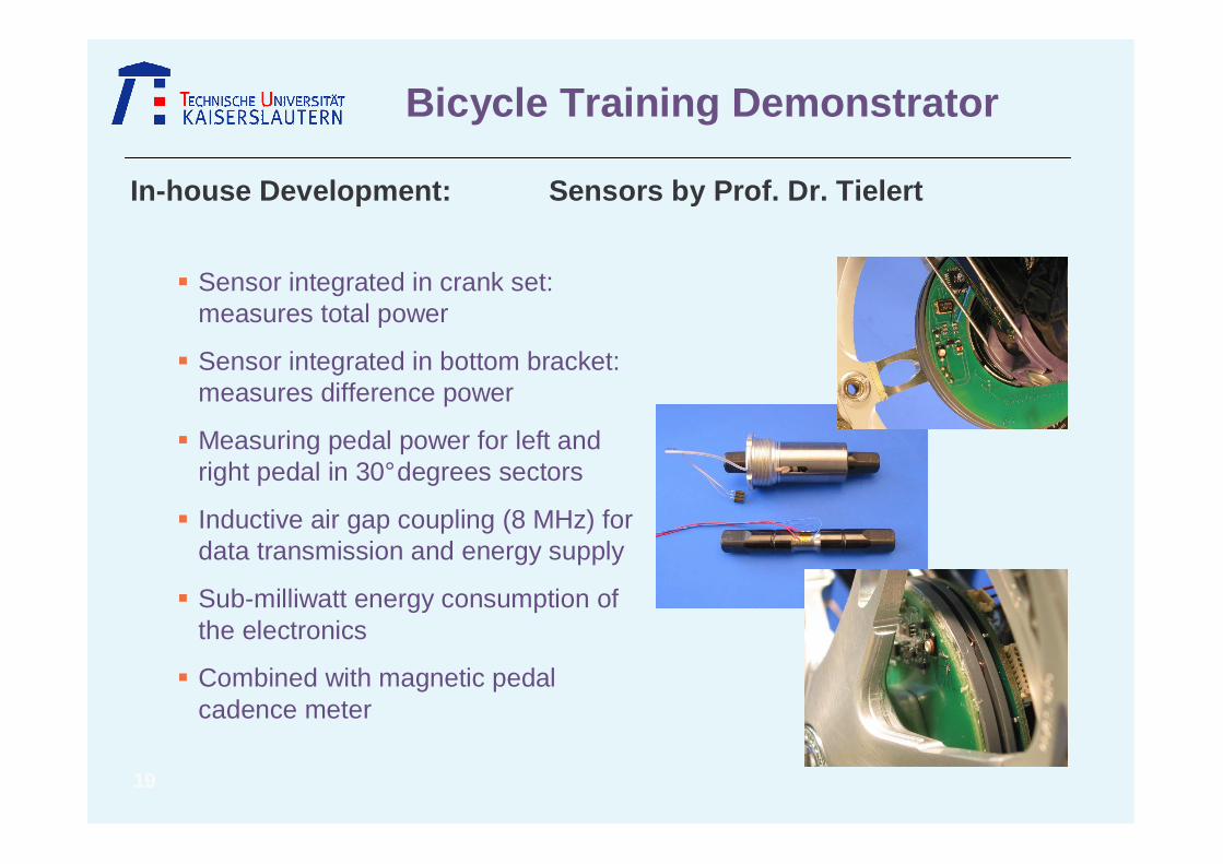
� Sensor integrated in crank set: measures total power
� Sensor integrated in bottom bracket: measures difference power
� Measuring pedal power for left and right pedal in 30° degrees sectors
� Inductive air gap coupling (8 MHz) for data transmission and energy supply
� Sub-milliwatt energy consumption of the electronics
� Combined with magnetic pedal cadence meter
In-house Development: Sensors by Prof. Dr. Tieler t
20
Bicycle Training Demonstrator
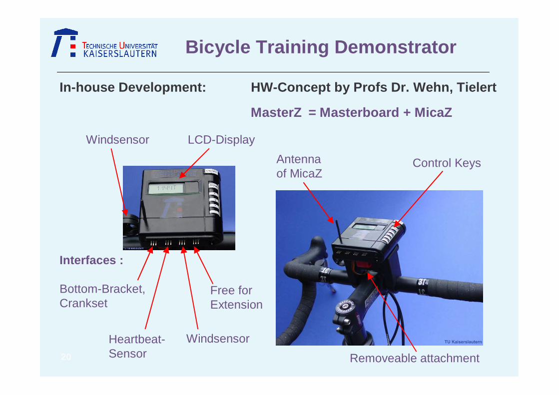
In-house Development: HW-Concept by Profs Dr. Weh n, Tielert
MasterZ = Masterboard + MicaZ
Antennaof MicaZ
Windsensor LCD-Display
Control Keys
Removeable attachment
Interfaces :
Bottom-Bracket, Crankset
WindsensorHeartbeat-Sensor
Free forExtension
21
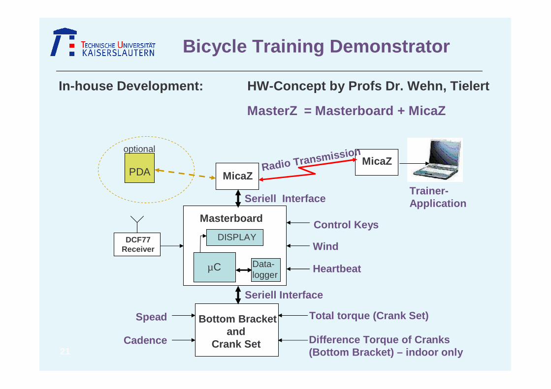
Bicycle Training Demonstrator
DISPLAY
Masterboard
Data-logger
DCF77 Receiver
Control Keys
Wind
HeartbeatµC
MicaZMicaZ
PDA
optional
Bottom Bracketand
Crank Set
Spead
Cadence
Total torque (Crank Set)
Difference Torque of Cranks(Bottom Bracket) – indoor only
Trainer-Application
Radio Transmission
Seriell Interface
Seriell Interface
MasterZ = Masterboard + MicaZ
In-house Development: HW-Concept by Profs Dr. Weh n, Tielert
22
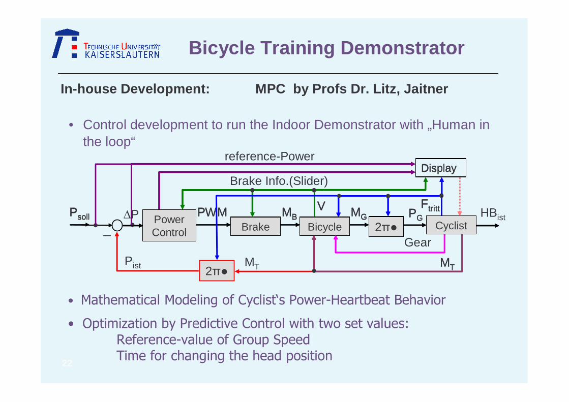
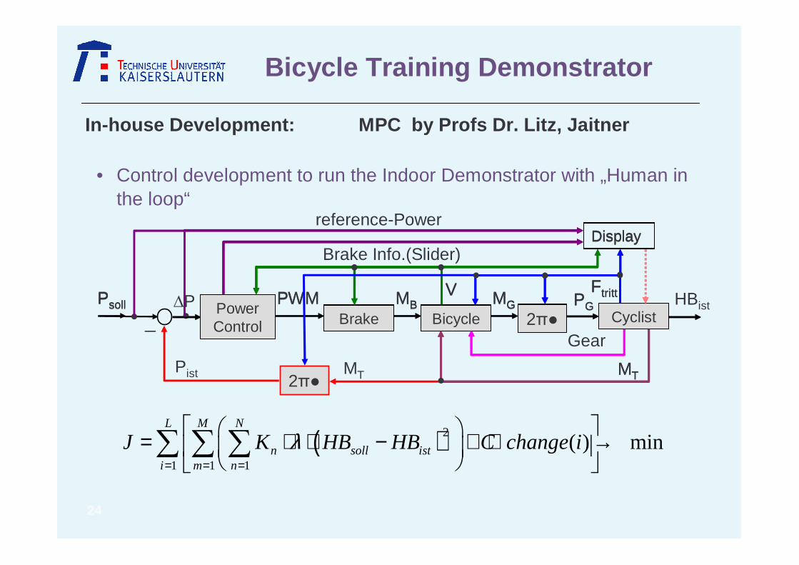
• Control development to run the Indoor Demonstrator with „Human in the loop“
• Mathematical Modeling of Cyclist‘s Power-Heartbeat Behavior
• Optimization by Predictive Control with two set values:Reference-value of Group SpeedTime for changing the head position
Bicycle Training Demonstrator
In-house Development: MPC by Profs Dr. Litz, Jai tner
PsollFahrrad
Leistung Regler
PWMBremse
MBMensch2
MG PG
Ftritt
Display
V
MT
PsollBicycle
Power Control
PWMBrake
MBCyclist2
MG PG
Ftritt
Display
V
MT
_
2Pist
P
MT
reference-Power
Brake Info.(Slider)
HBist
Gear
23
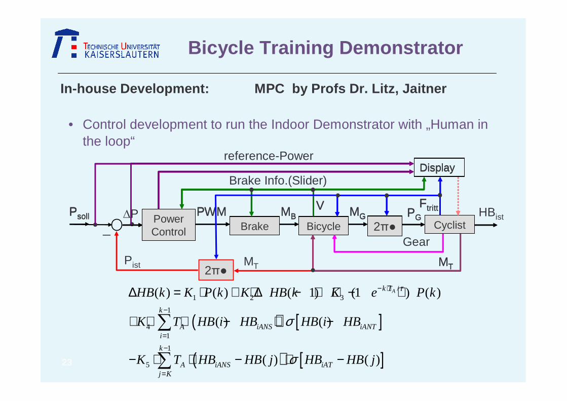
• Control development to run the Indoor Demonstrator with „Human in the loop“
Bicycle Training Demonstrator
In-house Development: MPC by Profs Dr. Litz, Jai tner
( ) [ ]
( ) [ ]
/1 2 3
1
41
1
5
( ) ( ) ( 1) (1 ) ( )
( ) ( )
( ) ( )
Ak T
k
A iANS iANTi
k
A iANS iATj K
HB k K P k K HB k K e P k
K T HB i HB HB i HB
K T HB HB j HB HB j
τ
σ
σ
− ⋅
−
=−
=
∆ = ⋅ + ⋅∆ − + ⋅ − ⋅
+ ⋅ ⋅ − ⋅ −
− ⋅ ⋅ − ⋅ −
∑
∑
PsollFahrrad
Leistung Regler
PWMBremse
MBMensch2
MG PG
Ftritt
Display
V
MT
PsollBicycle
Power Control
PWMBrake
MBCyclist2
MG PG
Ftritt
Display
V
MT
_
2Pist
P
MT
reference-Power
Brake Info.(Slider)
HBist
Gear
24
• Control development to run the Indoor Demonstrator with „Human in the loop“
Bicycle Training Demonstrator
In-house Development: MPC by Profs Dr. Litz, Jai tner
( )2
1 1 1
( ) minL M N
n soll isti m n
J K HB HB C change iλ= = =
= ⋅ ⋅ − + ⋅ →
∑ ∑ ∑
PsollFahrrad
Leistung Regler
PWMBremse
MBMensch2
MG PG
Ftritt
Display
V
MT
PsollBicycle
Power Control
PWMBrake
MBCyclist2
MG PG
Ftritt
Display
V
MT
_
2Pist
P
MT
reference-Power
Brake Info.(Slider)
HBist
Gear

25
Bicycle Training Demonstrator
Sensor Systems
� Wind Senor : field test
� Encoded Heartbeat : Tested
� Torque, Power: field test
Crank Set / Bottom Bracket
� Tested in laboratory environment,
Communication� System with multihop completed,
up to 32 bicycles, field tests running
ECG
� in development
Master Board� Tested and completed
Control Algorithms
� Model Predictive Controller: developed
in simulation environment, not tested
Outdoor training Tests
� Field tests with technical evaluation:
in preparation
Indoor training Tests
� Technical Evaluation planned for 7/2007
� First tests planned for 10/2007
Status of the development
Another In-house developments: Profs Gotzhein, R ausch
26
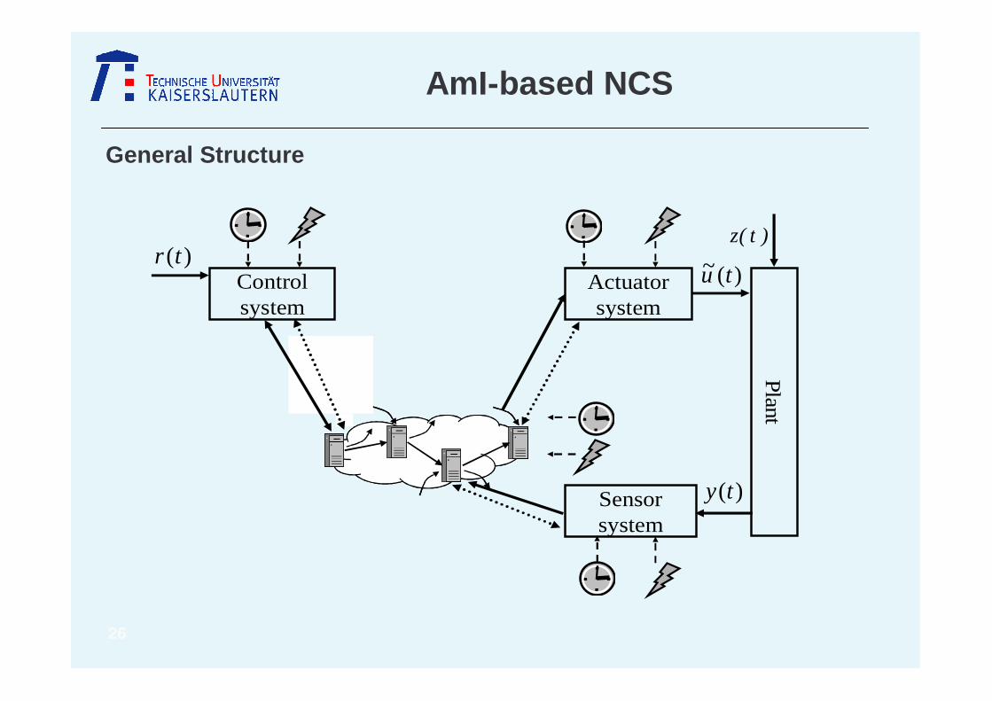
AmI-based NCS
General Structure
Actuator system
Control system
Sensor system
)(ty
Pla
nt
)t(z
)(~ tu)(tr
27
AmI-based NCS
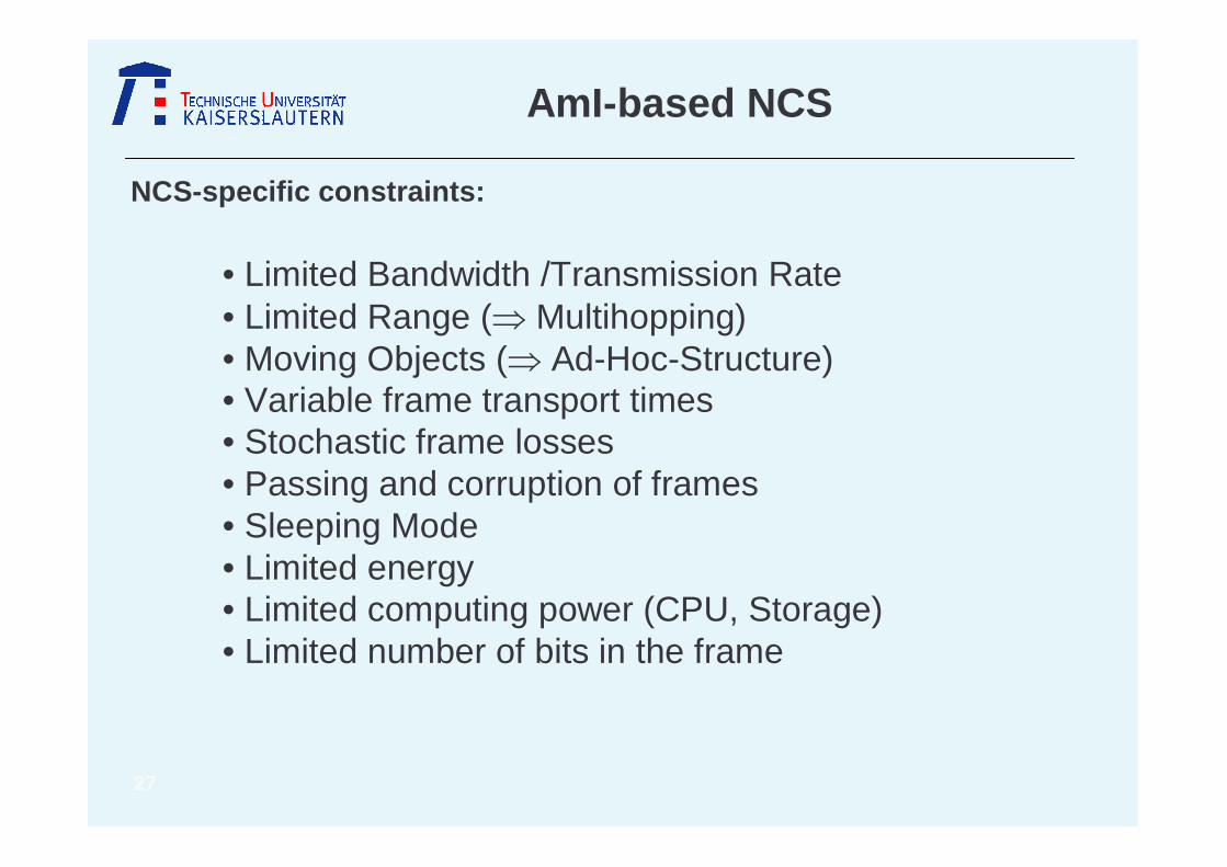
NCS-specific constraints:
• Limited Bandwidth /Transmission Rate • Limited Range (⇒ Multihopping) • Moving Objects (⇒ Ad-Hoc-Structure)• Variable frame transport times• Stochastic frame losses• Passing and corruption of frames• Sleeping Mode• Limited energy• Limited computing power (CPU, Storage)• Limited number of bits in the frame
28
AmI-based NCS
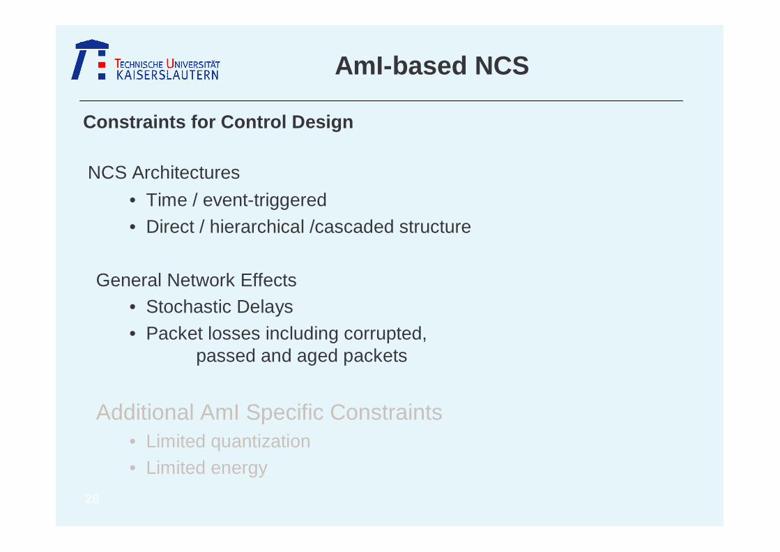
Constraints for Control Design
NCS Architectures
• Time / event-triggered
• Direct / hierarchical /cascaded structure
General Network Effects• Stochastic Delays
• Packet losses including corrupted, passed and aged packets
Additional AmI Specific Constraints• Limited quantization• Limited energy

29
AmI-based NCS
Constraints for Control Design
NCS Architectures
• Time / event-triggered
• Direct / hierarchical /cascaded structure
General Network Effects• Stochastic Delays• Packet losses including corrupted,
passed and aged packets
Additional AmI Specific Constraints• Limited quantization• Limited energy
30
AmI-based NCS
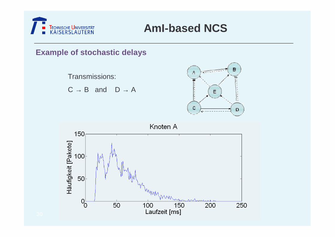
Example of stochastic delays
Transmissions:
C → B and D → A

31
AmI-based NCS
Our Attempts for Control over AmI-Networks
• MPC-based Adaptive Control
• QoS-adaptive Heuristic Control
• Time stuffing , 1,2,...SC C CA N
N S
T
T iT i
τ τ τ+ + <= =

32
AmI-based NCS
MPC – based Control
• Structure and Principle
• Detection of “Packet Losses”–– packet is corrupted or
– is lost
( , )SCy pn
1 2( , ,... , )CAu u u pnν
new lastpn pn<
, , 1,2,...SC SC CA CA SC CA ST T T T iT iτ τ> > + = =

33
AmI-based NCS
QoS-adaptive Heuristic Control
1 L new last new lastp pn pn pn pn= − − ∀ >
• Controller can – calculate transport delay τSC
– recognize the packet losses (pL)
– adapt to QoS
• Measuring the QoS– Sensor samples time-triggered– Clocks are synchronized occasionally
– 4-bit packet number instead of timestamp

34
AmI-based NCS
QoS-adaptive Heuristic Control
( )max
100 1 , 1
0 100, 0.5 e.g.
IEQoC IE IAE ITAE
IE
QoC
λ λ
λ
= − = − + ⋅
≤ < =
• General adaptation attempt– Offline calculation of the best controller individuals for
different τSC by genetic algorithm maximizing QoC– Online adaptation by switching to the best Controller
individual according to the measured τSC – Online adaptation of the sampling time T according to the
measured number of packet losses – Online adaptation by two further heuristic schemes to
increase the Quality of Control (QoC)• Comparison with a robust non adaptive Time-Triggered
Controller (TT)
• Definition of the Quality of Control (QoC)

35
AmI-based NCS
QoS-adaptive Heuristic Control
1
1 1 1 1
( ) 0.5 ( )
0.5 ( ) ( )
m m P m I m m m
I m m P m m
u u k k T e
k T k e
τ τ
τ τ−
− − − −
= + + ⋅ ⋅ ⋅
+ ⋅ ⋅ − ⋅
• Heuristics H1: Dropping of overtaken and corrupted packetsH2: Adaptation of control parameters according to the measured
delays τm
H3: Adaptation of the sampling time Tm according to the packet losses
H4: Immediate reaction on set point change
• Control algorithm
36
AmI-based NCS
QoS-adaptive Heuristic Control
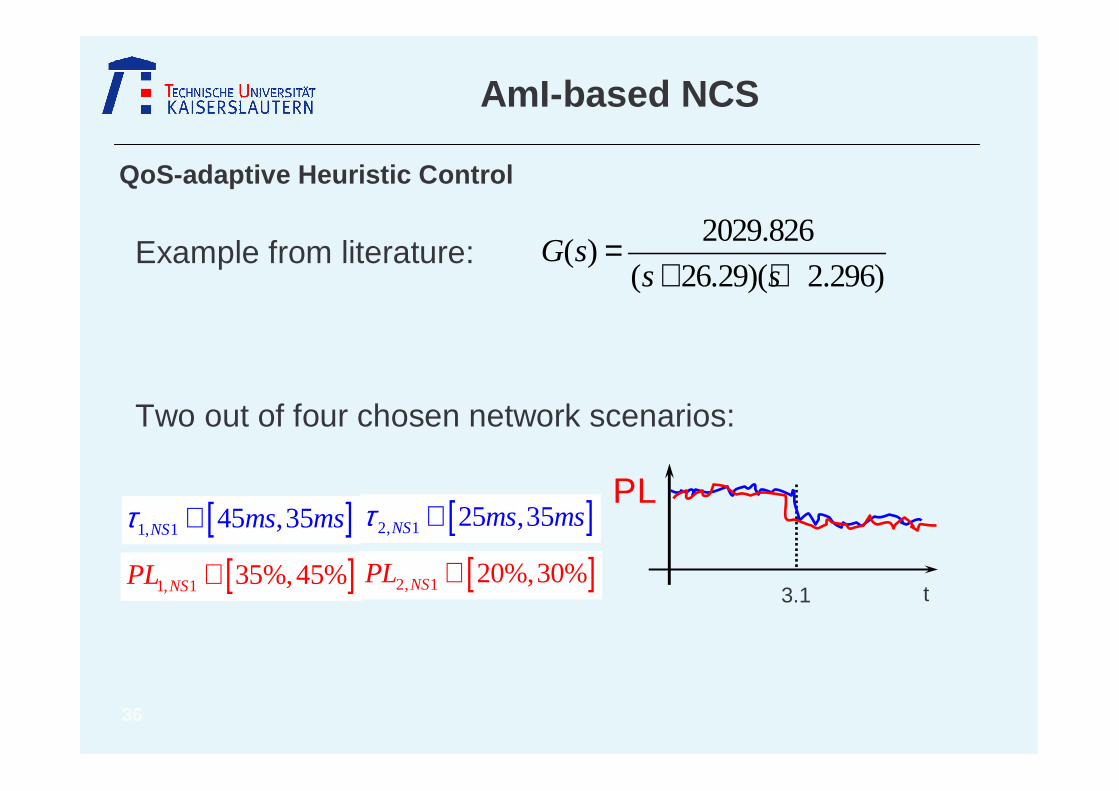
2029.826( )
( 26.29)( 2.296)G s
s s=
+ +
PL
t3.1
[ ]1, 1 45 ,35τ ∈NS ms ms [ ]2, 1 25 ,35τ ∈NS ms ms
[ ]1, 1 35%,45%∈NSPL [ ]2, 1 20%,30%∈NSPL
Example from literature:
Two out of four chosen network scenarios:
37
AmI-based NCS
QoS-adaptive Heuristic Control
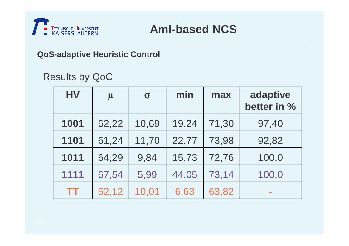
Results by QoC
-63,826,6310,0152,12TT
100,073,1444,055,9967,541111
100,072,7615,739,8464,291011
92,8273,9822,7711,7061,241101
97,4071,3019,2410,6962,221001
adaptivebetter in %
maxminσσσσHV

38
AmI-based NCS
QoS-adaptive Heuristic Control
0 1 2 3 4 5 60
50
100
150
200
250
300
350
400
Time (s)
Spe
ed (
rad/
s)
Comparison of 1111 and TT:
39
AmI-based NCS
QoS-adaptive Heuristic Control and MPC
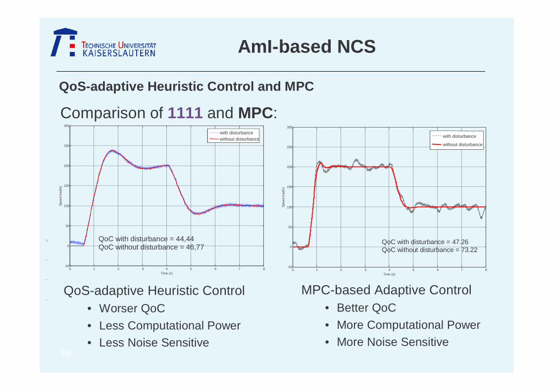
Comparison of 1111 and MPC:
0 1 2 3 4 5 6 7 8-50
0
50
100
150
200
250
300
Time (s)
Spe
ed(r
ad/s
)
with disturbancewithout disturbance
QoC with disturbance = 44,44QoC without disturbance = 46,77
0 1 2 3 4 5 6 7 8-50
0
50
100
150
200
250
300
Time (s)
Spe
ed(r
ad/s
)
with disturbance
without disturbance
QoC with disturbance = 47.26QoC without disturbance = 73.22
MPC-based Adaptive Control• Better QoC
• More Computational Power• More Noise Sensitive
QoS-adaptive Heuristic Control• Worser QoC
• Less Computational Power• Less Noise Sensitive

40
AmI-based NCS
QoS-adaptive Heuristic Control and stability proof
• BMI-approach for NCS (Yue, D.; Han, Q.; Peng, C.: State Feedback Controller Design of Networked Control Systems, 2004)
• Measure for Packet losses and delays:
• Approach: Lyapunov functional
• Stability condition:
...,2,1,)( 11 =≤+− ++ khii kkk ητ
0
***
**
*
333
23232222
113312121111
<
−++
−+−−−−−+++−−+−−+
T
NTMM
NMBKMNMBKKBMNN
NPMMANKBMMANNMAAMNN
T
TTTTTTTT
TTTTTTTTT
ηηηηη
0,0 >> TP
∫ ∫−+=
t
t
t
s
TT dvdsvxTvxtxPtxtVη
)()()()()( &&
41
AmI-based NCS
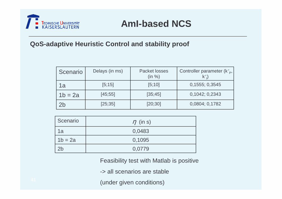
QoS-adaptive Heuristic Control and stability proof
0,0804; 0,1782[20;30][25;35]2b
0,1042; 0,2343[35;45][45;55]1b = 2a
0,1555; 0,3545[5;10][5;15]1a
Controller parameter (k’P, k’ I)
Packet losses (in %)
Delays (in ms)Scenario
0,07792b
0,10951b = 2a
0,04831a
η (in s)Scenario
Feasibility test with Matlab is positive
-> all scenarios are stable
(under given conditions)
42
AmI-based NCS
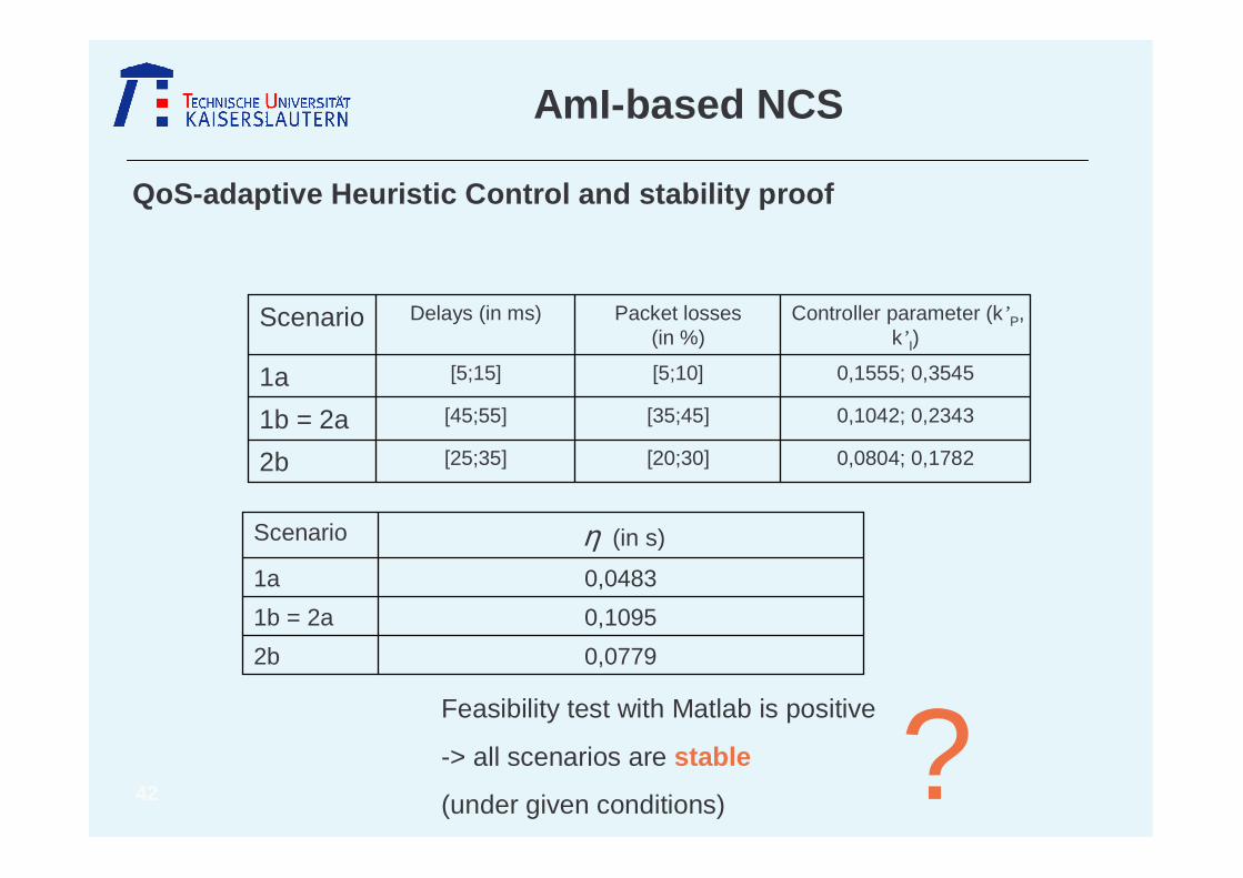
QoS-adaptive Heuristic Control and stability proof
0,0804; 0,1782[20;30][25;35]2b
0,1042; 0,2343[35;45][45;55]1b = 2a
0,1555; 0,3545[5;10][5;15]1a
Controller parameter (k’P, k’ I)
Packet losses (in %)
Delays (in ms)Scenario
0,07792b
0,10951b = 2a
0,04831a
η (in s)Scenario
Feasibility test with Matlab is positive
-> all scenarios are stable
(under given conditions) ?
43
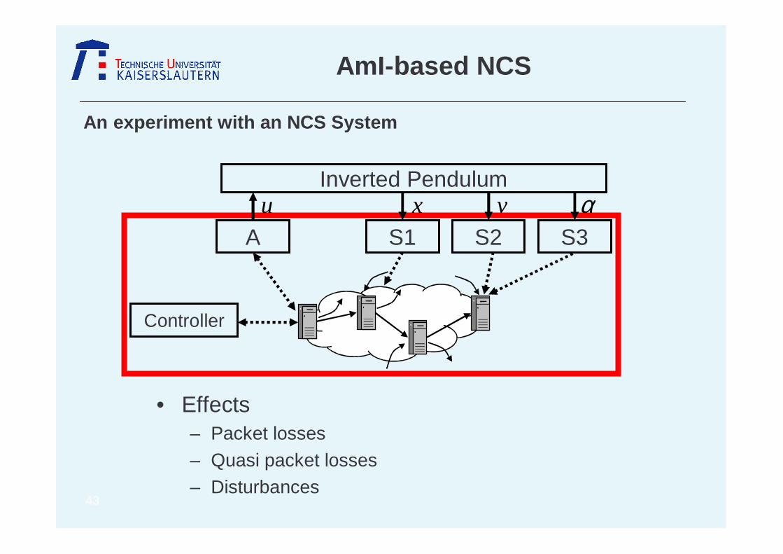
AmI-based NCS
An experiment with an NCS System
A
Inverted Pendulumu
S1x
S2v
S3α
Controller
• Effects– Packet losses
– Quasi packet losses
– Disturbances

44
AmI-based NCS
An experiment with an NCS System

45
AmI-based NCS
An experiment with an NCS System

46
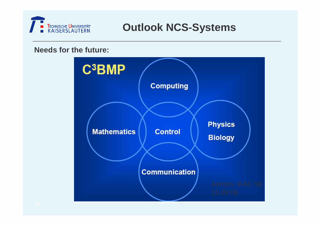
Outlook NCS-Systems
• Mapping of the technical problems to mathematical design methods
• Treating several limited resources at the same time
• Non conservative stability criteria
• Stability criteria for nonlinear systems
• Performance - measures for a proper judgment of different solutions
• Cross-Design-Methods with optimization of the trade-Offs
Needs for the future:
47
Outlook NCS-Systems
Needs for the future:
Astrom, IFAC 5015.09.06

48
Thanks for your attention !
49
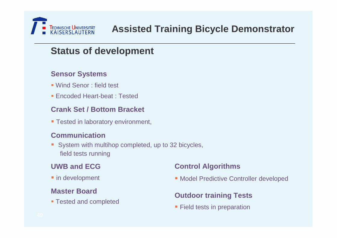
Status of development
Sensor Systems
� Wind Senor : field test
� Encoded Heart-beat : Tested
Crank Set / Bottom Bracket
� Tested in laboratory environment,
Communication� System with multihop completed, up to 32 bicycles,
field tests running
UWB and ECG
� in development
Master Board� Tested and completed
Control Algorithms
� Model Predictive Controller developed
Outdoor training Tests
� Field tests in preparation
Assisted Training Bicycle Demonstrator
50
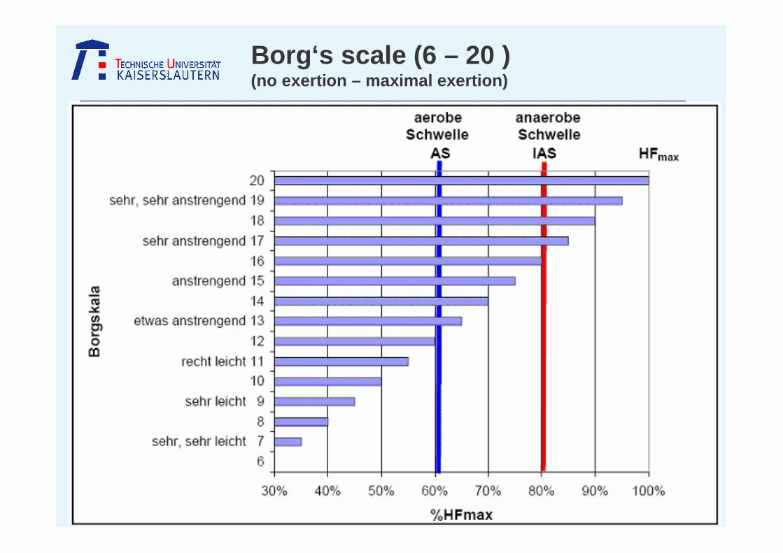
Borg‘s scale (6 – 20 )(no exertion – maximal exertion)

51
Slower group of cyclists
Communication range of slower group of cyclists
Forwarded by global broadcast routing if available
Multi-Hop Broadcast Routing

52
Hardware Concept
DISPLAY
Masterboard
Data-logger
DCF77 Receiver
Control Keys
Wind
Heart-beatµC
MicaZMicaZ
PDA
optional
Bottom Bracketand
Crank Set
Spead
Cadence
Total torque (Crank Set)
Difference Torque of Cranks(Bottom Bracket) – indoor only
Trainer-Application
Radio Transmission
Seriell Interface
Seriell Interface

53
Master Board
LCD JoystickBatterie Data Flash ATmega169
PiezoElement
Timer Oscillator (32kHz)
ATmega169 : 8 MHzFlash: 16 KbytesSRAM: 1 kBytesLCD Driver: 4 X 25 Segment
Data Flash :2048 Pages with 264 Bytes 4 MBytesMemory for 2,7h Training Duration(storing data every second)

54
S1
Push-Button
VccEXT
Heartbeat SensorWind Sensor
MicaZ
Power ON/OFF
DCF77 Receiver
Bottom BracketCrank Set
Master Board and Interfaces
55
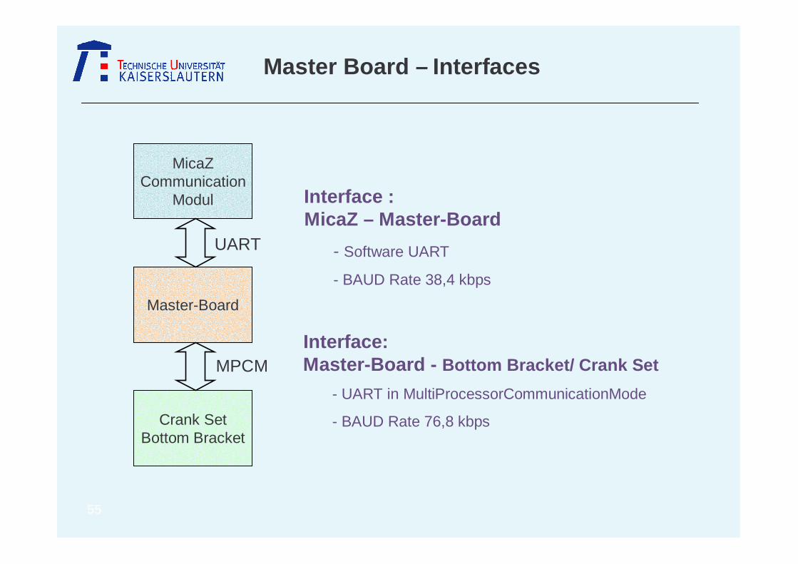
Master Board – Interfaces
Interface : MicaZ – Master-Board
- Software UART
- BAUD Rate 38,4 kbps
Interface: Master-Board - Bottom Bracket/ Crank Set
- UART in MultiProcessorCommunicationMode
- BAUD Rate 76,8 kbps
MicaZCommunication
Modul
Master-Board
Crank SetBottom Bracket
UART
MPCM

56
� Message Format (Masterboard MicaZ)
Length : Length of the message (Header+Data)ID : Bicycle-Identifikation (set by MicaZ)Type : Type of the message (DATA, COMMAND, SET-UP…)Version : Version of the message type
(<0x00>: Initialisation, <0x01>: Single Training, <0x02>: Group Training, <0x10>: Output Datalogger)
� Message Format (Masterboard Crank Set/Bottom Brackets)
Communication Protocol
0x020xFFDataVersionTypeIDLength0x010xFF
End Of FrameDataHeaderStart Of Frame
0x020xFFDataVersionTypeAddressLength0x010xFFAddress
End Of Frame
DataHeaderStart Of Frame
Address

57
Bicycle Training Demonstrator
In-house Development: MacZ - Layer by Prof. Dr. Got zhein
Communication requirements
� Spontaneous messages
� Sensor values
� Periodical data
� Messages with guaranteed delay
� Alert messages
� Voice communication
� Actuator control
� Enhanced- Best- Effort Transmission
� Distributed Multihop-time-synchronization
Synchronization of the whole network
after a constant time-delay
� Supporting different Transmission slots
Priority oriented transmission
Reserve oriented transmission
Alert messages
� Recognition of external networks
and automatic synchronization
Hybrid QoS MAC Layer
![Ambient intelligence : an annotated bibliography Project - ENG... · Ambient intelligence : an annotated bibliography 4/38 and guidance [10], [11]. AmI has potential applications](https://img.pdfslide.us/doc/110x75/5f87aca72618ed30f422df8d/ambient-intelligence-an-annotated-bibliography-project-eng-ambient-intelligence.jpg)