Embed Size (px)
Citation preview

VHF COMMUNICATIONS 2190
Maljai Vidmar, YT3 MV
Amateur-Radio Applications of theFast Fourier TransformPart 1
Thl••rtlcle I. more than Ju.t a de. cr lptlon ofthe lat••t .o"wa~ lor the DSP Com put... . • •Inter••ted rNder. will . oo n find out . NeverIhele••, It I. al.o a con llnuatlon ollhe ..rl• •01article. about DSP Technlqu•••nd wrltt.nby the .am. author .
1.INTRODUCTION
The Fast Fooner Translorm (FFT) IS a veryetlicienl numerical algorithm to compute adiscrete Fourier translorm. The FFT algonthmhas tounel many d.llerent Ilpplicetions anel Itis not lImited only to digital computers and digitals;gnll l processing. For example. a completelyanalog implementation 01 the FFT algorithm canbe made with a number 01 3 dB dl'ecllonalcouplers and delay lines to leed an antenna array.
Obviously the FFT algoflthm is widely u$&d indigital signal processing 100. In this article aparticular OSP application 01 the FFT algorithm
is described and discussed in detail: FFT spectrum analysis. Since the FFT algonthm can beimplemented on almost any digita l computer anda FFT spectrum analyzer only requires a erueadditional hardware, FFT spectrum analysIs ISvery convenient lor many practical applications
In order to unders tand the cce retcn 01 a FFTspectrum analyzer anel lts advantages and drawbacks when compared with other spectrumanalysis techniques . a short description ot thevarious souner transtorms and the operallon 01the FFT algorithm II Included. BUilding a preencally wOr1o: ing spectrum analyzer around the bareFFT algorithm Is also discussed No mamematlca! proofs are given just to keep the diSCUSeon as Simple as possible . The intereSled readercan lind the termer in almost any book describingdigital signal processing.
Although FFT speceum ana!ysis il presentlylimited 10Ihe euoc frequency range. al least loramateur resoeeces. It has many amateur-radiOap~ication s rallging Irom weak signal detection10 modulation analysis. A lew typical amateurapplicalions afe discussed letee In this article.including spaC1rum function plots anel IntenSity
123

apec::trograml Qblalned IT()m r..1 109"''' ulM'Iga FFT ipeCtnIm analyz...
Fnatly, a FFT ~ana/yl." program lorIN asp compul... . dnCflbe(f In UKW·BE·RICHTENHF COMMUNICATIONS. •• preMnlecl , inCluding • ~ dMCIlpbOn of Itacommandl and performance hmil. imposed bythe harctw.... All IN practrcal .xampln IhownIn thII artICle were obtained WIth It'll' IOh .,.
moat hgur_ "" ~ t\ardoopy pnnts 01 lhecompul... ICtMn on a ...... pnnIet
2.THE FOURIER TRANSFORM ANDTHE DISCRETE FOURIERTRANSFORM
,.... FCIl.II'* tr.".torm .. I mathemlll>Cel 0pera.
tion tNl computeS a ,.,..,.. Iunctlon F(U,l) from ...0flgINlI function ttll. .. If'v)wn In ng. 2.1. BoIhI\.InctJoM haw rMI argumentI l rod w... \hill'.,.... Ittl WId F{w' .... In gener" CO'fIPIexnumbers. F(w)" callId the Founer tranatorm of.gwen function ' II) ,.... Founer tr.,.form I\UIOrTlI inI.....tJng proper1lft1 II'ldudtng a relatrvely"""P'- InVefM oper.f1On : compullng 1(1) back!rom I given F(uol II vetY "milar 10 !hi FouOll'traNform IIMII.
Ifill
VHF COMMUNICATIONS 2190
The Fourier transform .. trequanIty uMd inphyla to c:ompul. the frequency apectrum of I
~ ptly..caI QUanllfy . I" a phyIlealproblem I reprlMn1l time and 1(1) repntWnl. I
~ QUArlllly (force,clI~, pteuurl,
IIectricaI cvrrentor voltage) U I luf'CtlOl'1 of lWM.
1".11 ptlysical probllmll(I)"1 rill luncbOn . ThlI,........ Ylrilble w raprIMntllht Irequency and hfur1ctJon F{w) II !hi frequency IJ*lrUrn of lhephyIQl QLWtIrty otJIIl'Oed. The Iraqoaneyapactn,ln'llil CO'fIPIex tunctJon OIl real YanaDlI.... The~ .,.,. 01 Ft",) rlPl'_ the
rMgnItUde oilgrven apedr"~ III Jl.-.d tnIargumenI 01 F{w) ' . ..... trill phue relatNIto IN (c::hoMn) Ilrne ongwl. Sonca ttll II IlwartI real function one doN rKlC rMIy naecI 10 compull F(w) lor ,.g.w. ,,~ F(-.) iIWfI9IY !hi complIx-eonjugaill fA F(w} lor I .....
'(I) .
WhlIeh Founer transtorm II I powartuI anIIiytI.cal 1001 to PII'form lhIorICaI compu1abOl'1lII hal II least twoCIClnItrIlntl wf1lC:tI coukl ,......,be IuIfJllId In prKbeI Infnte brdwilfttl andInfnta~ F'I«JkItJOn (whICh~ aninfIMa obIItYltlOtl """). regamlII fA themathocl . analog or~. uaecl 10 partonn !tilFouriertranstorm
A rHi-wond . ftrlll~ IlQf'IaI can bI..m plecl w JthouI IooIlng Iny InformabOn proYIdecIlhallhe umphng frlQuency Ia high 1I"lClUgh.al Ieut I'WlCI IhI IIgnal bvdwidth The FOUfIIt'
-.~
Few) ' \ j ll\ e'-'.t
."".
Ag. 2.1.:_.....!'oun. T..-f_

VHF COMMUNICATIONS 2190
H {t)
• t , I . -~....
F{w) F~ . 2.2. :
Four" Trl nafofm of IUI'lp6ecl-'gnal
transtorm of asampled signal is shown In lig. 2.2..The integra! is replaced with a sum. the bounds ofthe sum are. however, 11111 inhMe. An Importantd,nerenoa should be noIiC8d in pIoI 01 F(IJl): lhespectrum Of a sampled so;nal II a petiodictunctlOn lind 111 paned II InVersely proport lOflalto Ihe tampling peood. 11 II lh8I'elore SUnlCl8nl10 compule (either 10 an analog or In a d.gl1alway) JUIl one penod of F(wl . usually betWeen- ,,/Al and ... ,,1tJ.1.
The (original) Fourier tranl torm Integral (or lum)hal Inhnlte bounds : lhe integrelion (or lummal ion) l hould be per10rmed from minus InflM y toplUI lnflnlly . 01 course no r.al-WOt1d lignal willever lall thal long! It is lherelote complete lySUnlClen! 10 compute the 100"9"al or the sum only
over the tlme lnter'llal when lhe s.gnal . xII II . Inte·oraling ove r a l iMa amount ot time limIts thafrequency resolution , wtltch '1 inver..1y proporttonal 10 Ihe inlegration l ime . Thll ImpliesIllal the frequency spectrum could also be repra.ented by dllCrele sample l In place 01 aconIinUOUllunc1lOn,
The procedure that comput el a liMe number01 apeclral lines lrom a liMe "umber 01 IIgnalaamplal II celled lhe Oll,crate Fou~r Tra"llorm(OFT) and II l hown In fig . 2.3. To properlydescribe Ihe signal lpectrum one need s al laalltha lame number of frequency lamplal as Ihel'aara I" pul " O"al samplel . Of cour i . , to obta,nmean ingful resuil i . Ihe jrequency Inlarva l (specIral lIne spaCIng) hal 10 be choHn I" a cloaa
Fig. :l.3.:o.flnitlon DItna 0Iaem.Fout1af Trln.rorm
125

If'.J
I
•
• -I Fe....)
I.~TTI' --:-I .• (I..;:'..,)
VHF COMMUNICATIONS 2190
Fig. :1.4.;Norml llZltlg 11_ and"-qu_ y unll •
relatlOflshlp 10 the t,me 'nterval (lIlgna' umpllngstep). Simlla, coostra,"11 alao apply 10 a conple tely analog Foufla' Iranl lorm (analog spectrumanalyzer).
In order to limphty compulallonl, bolh Inne andf' equency uOllS are usually normalized to 1 aaeecwn in fig . 2.4. Time t now only lakea thavalues 01 0 , 1. 2.... (N - 1) and trequency ( ,j alsotakes lne values 010, 1. 2.... (N - 1), Il lhe discreteFouner transform produces N $p8Clral ltnea IromN lignarsamples Asa reaull ol lh'S normalisatIOnthe coos iao t 2 .,../N appear. in lhe complex ex·ponent 1unc11QO Th,. coostanl i. chosen suchthat the result ing spectr.' hoea cov... exactly ooepenod cu-e perIOdIC llOnal spectrum
The OFT can be computed on any genera!·purpoae comput.... III 098"01 '100 II limilar to Nbandpass FIR hltera. each1,Ita' haVIngN stagesand I\Jnad to III own Irequency . The OFT I' octcomputatlOf'lally alflC!."I , Since the number Ofcompulaliona required increasea with N'. IllheOFT II COmputed on a real , lgna l (r.al f(t)) w'th Na'gnal samplea, then the result ooly IncludesNl2 , pectral line, rang,ng lrom sere to hall theaampl'ng frequency. The remaining N/2 spect rallines are limply compla. conjugales lhal can becompu ted ,n • much s,mpler way onee the IIfSINI2 spectral hnes are known, reducing lhe lotalnumber 01cornputabOf'll requlfed to abOut N' f2.
Will be continued
A must for all active and technically minded Radio Amateurs!
THE UHF-COMPENDIUMThe English edrtrcn 01the well·known " UHF·Unterlag e" l rom Kar l Weiner , OJ 9 HO.
Part 1 and 2
Part 3 and 4
Art.No. 8054
Art .No. 8055
OM 52.00
OM 58.00
Add,tlOf'lal post and package ettargel(surlace ma" ) lor ,nland OM 500. klr abroad OM 650
T....o~...........e--..UI(W·T_ _ T...,D.BIft8oI
............ l ~ . O..."'23....-..oorf. T,""",,, IO ll nl~ 11l. T.....H ..'
".

VHF COMMUNICAnONS 3190
Matjaz Vidmar, YT3 MV
Amateur-Radio Applicationsof the Fast Fourier TransformPart 2 a
3.THE FAST FOURIER TRANSFORM(FFT) ALGORITHM
The Discrete Fourier Transform supplies a veryuseful result, but unfortunately requires a verylarge number 01 computations on a digital computer or a very large number ot components Itpertormed by an analog circuit. A more efficientalgorithm that provides exacnythe same result asOFT with a considerably smansr effort required iscalled the Fast Fourier Transtorm. As an example, to compute a 1024 data point OFTthe FFTalgorithm requires about 200 times less computations (or analog components) than a straightforward OFT. Further. the number 01 cornpu-
tations required in Ihe FFT algorithm is onlyproportional to N/2 • log 2 (N). The FFT algorithmcan therefore be performed on a very largenumber of data samples without significantlyincreasing the number of computations persample.
The basic building block 01 the FFT algorithm iscalled a "bunarny" operation. A "buttertly'"operation consists of a phase-stun operat ion anda sum/difference operation. It operates on twoInput variables and produces two results. A single'"bunertly" operation can already compute a 2point FFT. as shown in fig . 3.1. In the case of a2-point FFT, Ihe two input variables are the inputdata to the FFT algorithm and 'he two results arealready the result of the algorithm. The phaseshih is equal to IT in 'his case.
f(4)
130
F(II =~Ol" • I( '10"
FlO) ~ 1(01&" ~ 1(' I....
Fig. 3.1. :Two-polnl FFT - a single"bunerfly" operation

VHF COMMUNICAnONS 3190
110)
\ II)
F( I) = ' (0)"" • 'I' I~.n • ' (2)0" , ' (3)...•
F131' 'IOJ"'" '( 01...• • '1>1'" • '13)0""
F(OI = '101" • 1(' )" • '12toP • 'OJ"
Fig . 3.2.:Four-point FFT, computedeach using two <bunerfly"'operations
FIg. 3.2. shows how a 4·poinl FFT works, A 4·point FFT is computed in two stages. Each slageIncludes two "butterfly" operations. In the lirststage. all phase shills are oo.ual to IT. In thesecond stage, the phase shilts are "12 and tt,
Note that each output 01 the /irst stage "butterflies" is led 10 exactly one input 01 the secondstage "butterflies" . Considering the periodiCityofthe complex exponent function. the four outputscorrespond exactly to the result obtained with astraightforward DFT, the laner, however. requires
16 phase shilts (8 if one does not consider zerophase shins) compared to the 4 phase shltts ofthe FFT algorithm.
Similarly, as-point FFT is computed in threestages as shown In fig. 3.3. Each stage includes4 "butterfly" operations. Again. in the first stageall phase shills are equal to.,.. In (hesecond stagelhe phase shifts are ITI2 and tt . In the third stageth'e phase shills are 11/4. trl2 , 3 • "/4 and n. Thealgorithm block diagram Iouows a regular patterntoo. suggesting that a FFT algorithm working on
1"0 1 - " a)ollP • I ( I~' • tlll!""- • I{) IO"""" • II .~ • If~le'-" r\!;..,r' , • '11te'"
"'l'!t.~. f{O' .' • rll~ • J(Z;-r"" . 1f3,M'· ·· • r(...!'It' • Il~¥ '. 1(&1""""" • IP )lI'"""
FIg. 3.3.: Elght·polnt FFT. computed In three steps, each using four "butterfly" operations
t31

VHF COMMUNICATIONS 3190
Fig. 3.4.:ObtainIng a doublelength (2N) FFT fromtwo single-length (N)FFTs
..,
' (01
H1N . I.J
fI2"' -2')
1( 1l r(~·\)
l(JI n..·1)
ObbN'f.'~\. FFT........."
rLlN - J ) ~It~-.)
1'2N. t ) H & F(0)
an arbitrary large number of samples could bedesigned in a similar way. In the case of an B-pointFFT, only' 2 -bunerllies" are required compared10the 84 shif1laddoperations of a straighl10rwardOFT algorithm to gel the same result.
To design FFT algoritms. operating on an evenlarger number of data samples. one shouldtherefore investigate Ihe possibility of comb iningseveral FFTs computed on a smaller number ofsamples. Fig. 3.4. shows how to combine twoN·point transforms (not necessarily computedusing the FFT algor~hm) into one single transformon 2 N (twice the number of) points. In additionto the two N-point transforms, N "buner1lies"are required. These "butterflies" requxe N different phase shilts ranging (rom II/N. 2 • ;rIN.3. ;rIN... (N - 1) • «IN , ;r in steps 01 ;TIN.
The principle shown in lig . 304. is in tact used todes ign a FFT algorithm operaling on any datalength N Ihal is a power 01 2. A FFT algorithm canthus operate on 2, 4. B. , 6, 32. 64, , 28, 256. 512., 024 ... data points . The 4-poin( FFT can bedenved from the z-coim FFT. Ihe a-point FFTcan be derived from the 4-poinl FFT, Ihe ts-pointFFT can be derived Irom the S-poinl FFT etc...
132
Each doubl ing of the data points only requiresan addltinal stage so the total number of stagesis equal to log 2 (N) . Each stage requires NI2"bunerf lies" . The total number 01 "butterfly"operations is therefore equal to N/2 • log 2 (N) .
A quick Look at fig. 3.3. shows that Ihe resultsdo not appear in any reasonable order at theoutput of the FFT algonthm : t, 5, 3, 7, 2, 6, 4, O.Coms idenng the construct ion principle shown infig. 3.4 .• a very simple rule to find the desiredoutput can be iound , This rule is called bitreversed addressing and it is shown in fig. 3.5.for the a-point FFT exarnpte. To lind an outputnumber one has 10take the corresponding inputnumber, write this number down in binary formal ,reverse the order of bits, convert the numberback to decimal and add i. This rule can beeasily implemented in digital hardware (deorcared OS? microprocessors). where data isstored in consecutive memory locations.
To implement the FFT algor ithm. a number 01' butter1ly" operations have to be per1ormed.An analog implementation called the "Sutlermatrix " uses delay lines to obta in phase shinsand "rat-race" hybnds or 3 dB direct ional

VHF COMMUNICAnONS 3190
couplers for Ihe add/s ubtract opera tions . TheInpUIS 01 the FFT circuit are connected to theelements of a linear antenna array and Ihe outputs of the FFT circuit to receivers and/or transrnitters, Since Ihe required phases and magnitudes of the signals feeding an antenna arrayare the Fourier transform 01 the desired radiationpattern, the outputs of the FFT circuit corresponddirectly 10beams in Ihe various direc1lons.
Implementing Ihe FFT algorithm on a digitalcomputer most operations are performed withcomplex numbers. Although phase shihs areeasier 10 perform II comp lex numbers are heldin a magnitude/phase format, sums and diHerences require a real/imaginary-componenlnumber format. Since conversions Irom onenumber format to another are very time-con
suming, all ccrnputations are usually done inthe reallimaglnary-component format. In nuscase a phase-shift operation requires lourreal mulllplications wilh coefficients trom aprecomputed table 01 phase shifts and twoadditions. Each summation of two complexnumbers requires two real summations andeach complex dilterence reqUIres two realdifferences.
The phase-shift coefficients are precomputedand stored in memory, since only N dinerenlcoetilciems are required In all stages 01a N·pointFFT. The same coetiicients can be used in the101l0wing FFT, il a number 01 FFTs have to becomputed on changing data . Finally . the phase coetfic ienttable Includes sines and cosines whichare much mo re lime-consuming to compute thanthe multipl icat ions and addn ions requ ired lor theFFTilsell .
If a FFT ;s computed on real data , then only halfof the outputs contain interesting data. Ihe other
half are just complex conjugates. To use thealgor ilhm more efficiently, another set of inputdata can be litled into the imaginary part 01 theinput variables. Alter Ihe FFT alqornnrn is pertorrned, the two results can be separated bysimple additions and subtract ions using thesymmetry laws 01 the Fourier transform. 1/ de sired . Ihe two results can be further combinedInlOa Single, double lenglh FFT.
The inverse OFT can easily be performed usingIhe FFT algorilhm in Ihe reverse direction. Thenumber 01 mathematical operations is identicalexcept lor an additional division by N lor eachdata point to obtain the or iginal magnJIude back .
There are even mo re eHicienl algorilhms tocompute a OFT or ils inverse. All of them are.however, based on the FFT princip le describedabove and require a lillie more programmingenorts to further reduce the number 01 computauonsrequired.
4.SPECTRUM ANALYSIS USING THEFFT ALGORITHM
One of the most obvious applications of Ihe FFTalgorithm is a FFT spectrum analyzer. The FFTalgorithm itse]! is performed on a dlgllal computer,usually a DSP microprocessor. The input signal isprovided in a dig itallormat from an AIDconverter.The microprocessor itself can display the result Ina variety of formals.
However. 10bUild a digital FFT spectrum analyzersome additional functions are required. A block
flO) »---> 0 0008 »---> 0008 0 0 .. 1 e 1 »--- > 1"(1)f(l) »-- -> 1 :: 0018 »---> 1008 4 4 .. 1 :: 5 »---> F(5)t(2) » - - - > 2 :: 010B » - --> 0108 :: 2 2 .. 1 ) »---> F(3)f(3) » - - -> 3 e 011B »---> 1108 :: 6 6 .. 1 7 »--- > F(7)f(4) » - - -> 4 1008 »--- > 0018 e 1 1 + 1 2 »--- > F(2)t(5) »---> 5 1018 » -- - > 1018 :: 5 5 .. 1 6 »---> F(6)f(6) » - - - > 6 1108 » - - - > 0118 3 3 t 1 :: 4 »---> F( 4)f(7) »--- > 7 :: 1118 »-- -> 1118 :: 7 7 + 1 B » - - -> F(O)
Fig. 3.5.: Output bl, -reversed mapping lor aeight-point FFT
133
tnpwt
,.",,109
It>lfUB
It t t e r
A/OtOh¥ ee
lor
VHF COMMUN ICAnONS 3190
YT3MV
rr I
a 19'od lha
Fig. 4.t.: Block diagram of an FFT spectrum analyzer
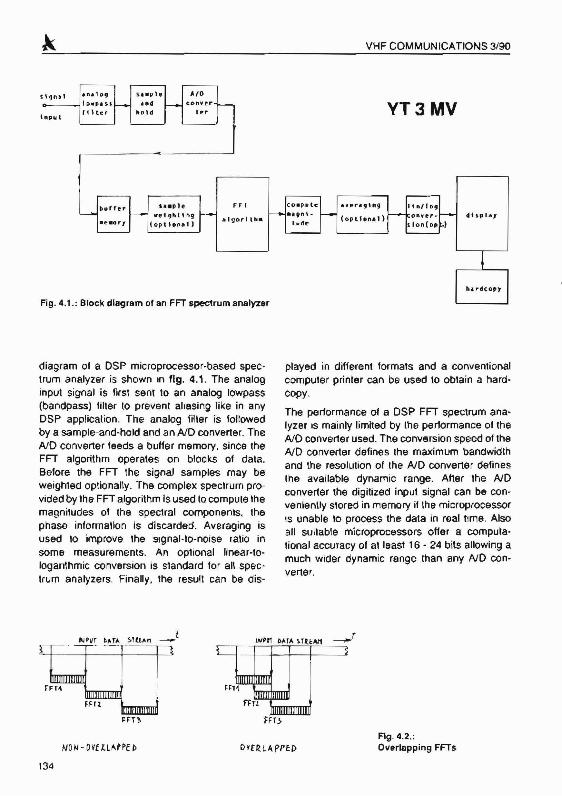
diagram 01 a OSP microprocessor-based spectrum analyzer is shown In fig. 4.1. The analoginput signal is flrsl sent to an analog lowpass(bandpass) lilter to prevent aliasing like in anyDSP application. The analog liller is lallowedby a sarnpte-and-hold and an AID converter. TheAID converter leeds a buffer memory. since theFFT algorithm operates on blocks 01 data.Belore Ihe FFT the signal samples may beweighted optionally. The complex spectrum provided by the FFTalgorithm Is used to compute themagnitudes 01 the spectral components, thephase informallon is discarded , Averaging isused to improve the slgnal·to-noise ratio insome measurements. An optional linear-toloqanthrnic conversion is standard lor all spsc trum analyzers, Finally, Ihe result can be dis-
played in different torrnats and a conventionalcompuler printer can be used to obtain a hardcopy.
The performance of a OSP FFT spectrum ana·Iyzer IS mainly limited by the performance 01 theAIDconverter used. The conversion speed 01 theAID converter defines the maximum bandwidlhand the resolution 01 the AID converter definesthe available dynamic range. After the NOconverter the digitized input signal can be conveniently stored in memory if the microprocessorIS unable 10 process the data in real time. Alsoall suitable microprocessors offer a computetional accuracy of at least 16 • 24 bits allowing amuch wider dynamic range than any NO converter.
NOil - DVE UMPE ~
_t
FIg. 4.2.:Overlapping FFT$
13<1

VHF COMMUNICATIONS 3/90
HJPln'>AI\I'IH
(fw 'I M~)
W(l(,Hl l'J~
FUNC110M
OVHVl~/l.n!ll~
(1 0 HT)
Fig. 4.3.: Weighting slgnel samples
Even i/ the DSP microprocessor is last enoughto process all of the data in real time. the inputdata stream has 10 be sent 10 a buffer memoryfirs\' since the FFT algorilhm operates on blocksof data. not on single samples . Without weighllngFFTs are usually performed on contiguous. butnon-overlappinq blocks of data to obta in almostall of the spectral informalion contamed in theinput Signal.
In the case 0/ inpul signal weighting. 'he contnbution o/Ihe samples at the beginning or at theend 01 a block is very limited. To use all of theinformation comained in the input signal overlapped FFTs have to be perlormed. Both casesare shown in fig. 4.2. In the second case theover lap is set to about 50 % for a raised-cosineweighting function.
II the FFT algorithm is performed on a raw.unweighted block of data . the correspondingspect rum is distorted. Since the FFT does notconside r any data samples before the block norany data samples after the processed block ofdata . the actual input signal 10the FFT algorilhmcorresponds 10 the real Input Signal modulatedwiTh a rectangular impulse ot Ihe length of thedata block. A rectangular impulse wilh steep
Fig. 4.4.: No weighting (above) versus raised cosine welghtlng (below). same Inputsignal. LOG vertical scale
leading and Hailing edges has a very wide [requency spectrum of the form sin(X)/X. Theresulting output will be the real signal spectrumconvoluted wilh the sin(X)/X function .
Although Ihe real signal spectrum can not beobtained since il requires an infinite amountof time, a much more accurate spectrum can beobtalned by weight ing the signal samples asshown in IIg. 4.3. Weighting means mUlliplying
.35

each signal sample with a constant whose valuedepends on the position of the sample inside Iheinput data block . The pracucat effect of weightingIs 10 replace the abrupt ONIOFF transitions Withsmoolh transit ions at the beginning and allhe end01 the data block. Welghling funct ions are selected 10 minimize the distort ion of Ihe signalspectrum . Raised-cosine and Gaussian functionsare usual choices . since they have a very narrowown spectrum wilh low side lobes.
FIg. 4.5.: No averlllging (above). averllglng 4 times(below). 68me Inpot signal end othersettings es In fig. 4.6.
136
VHf COMMUNICATIONS 3190
The effects of no weighting versus weightingare shown in fig. 4.4. The two plots show Ihespectrum of the same signal obtained in twodifferent ways . A linear 512-point frequencyscale is used on the horitzonlal axis and alogarithmic arnplnude scale (15 bits or 90 dBIfull scale) is used on the vertical axis. All theparameters. including the input signal . are thesame for bolh plots except for weighting : theplol above was obtained without any weighting
rue 1(11 ROT : ~·. El'':'; Hl; I.\I"""
r-Jlr: -. IU' ~
I
rc!CTICli FtOT: ':'£>;';1G So! I Ke<' ?J~
Fig. 4.6.: Averaging 16 Umes (above) or 64'Umes(below). same Input slgnel end othersettings as In 119. 4.5.

VHF COMMUNICATION S 3/90
while the plOl below was obiamed with a raised cosine weighting. Raised-cosine welghllngclearly provides much more clear spectral lmes,w ith no INEXISTENT sidebands. On the otherhand. weighling slightl y reduces the frequencyresolut ion mak ing the peaks broader. Selecllngweight ing or not is therefore a tracecn betweendynamic range and frequency resolu tion.
II a measurement is anecred by random noise .averag ing among a number 01 otherwise rdent icalmeasurements Improves ihe accuracy of theresul t. Automatic averaging is very easy to irnplemenl on any microprocessor-controlled testequipment. Averaging is used in spectrumanalyzers to improve the slgnaHo·nOlse ratio otthe displayed data. The Improvement lhat canbe obtained by averaging is shown 10 fig . 4.5 .and fig. 4.6. All four plots were obtained /rom Ihesame input Signal in an identical way except lordiHerent amounts ot averaging.
The linear-to-logarithmic conversion Includesthe computalion of a logarrthm lor each spectralcomponent. Since the loga rithm IS a rather 'slow'tunction on digilal computers, a look-up-tablealgor~hrri or a Similar approach has to be used10 avoid unnecessary load ing 01 the computer.The same constraint applies 10 Ihe displayprocedure: most computers require more llme10 draw a hlgh -resoluhon plot than to computethe FFT algorithm. The display rouune and /ordedicated hardware has to be quick enough 10avoid slowing-down lhe spectrum analyzer. OnIhe other hand . a hardcopy 01 the Video displayis usually very easy to obtain on any computerusing a standard printer or plotter. at least whencompared to analog instrumentation with CRTdisplays.
Besides the conventional frequency/amplitudelunction plot other tyP&s of display are possibleon digital computers. A practically very usefultype of display is the intensity spectrogram. Inthe latter frequency is still plotted on lhe horl zontal aos. Each FFT resull is, however. represented by a single-Image line and the pixelbrigh'ness is used to represent lhe maqnnuoeof a spectral component. The results of successive FFTs are plotted on successive lines .showing the results of a large number 01consecunve measurements on just one computer screen .
lntensiry spectrograms are useful when analyzingconunuously changing Signals
The display ot a FFT spectrum analyzer usuallyIncludes Ihe complete frequency range coveredby the FFT algorithm: Irom zero to half the signalsamp ling frequency The frequency resolution isthen Simply equal 10 the frequency span dividedby the number of lines displayed. The frequencyresojutioo may be shghliy worse if weighl ing isused in tront of lhe FFT alqontbrn. Of coursepartial displays are poss ible too. showing jusl asubset of spectral lines computed by the FFTalgorithm. The sarnpte-and-hotd circuu In frontof (he AID converter is an excellent harmonicmixer II is mererore pcssib fe 10 observe a dlf·ferent frequency band JUSt by replaCing the inputlowpass filter with a bandpass lilte r lor theselected frequency range .
Finally , a comparison has 10 be made betweena FFT-based spectrum analyzer and a scanning'receiver type spectrum analyzer (conventionalanalog RF spectrum analyzer) Of course ascanninq-receiver type spectrum analyzer couldbe implemented on a digital computer as well.A FFT·based spectrum analyzer has. however.a very important advantage over a scanning'receiver spectrum analyzer: regardless of thehardware used the FFT spectrum analyzer usesIhe avauaote specual information in a muchmore eHicient way resulting In a much Quickeroperation .
As an example. consider that a 5 kHz wide trequencv band has to be analyzed 10 a resojutlon01 10Hz. A scann ing receiver With a 10 Hz bandWIdth has 10 dwell on each 10Hz trequency stepfor about 0 1 seconds. result ing in a total sweeplime ot about 50 seconds! On lhe other hand. aFFT-based spectrum analyzer needs 10 samplea 5 kHz Wide Signal wllh a samphng frequencyof 10kHz A 1024'pOIn( FFT has 10 be used toobta in a 512·poinl display. so the total •scanning"lime is 0 ,1024 seconds!
In the above real-wend example the FFT speclrum analyzer is aboui 500 limes fasler! Thereason for thrs IS (hal a conventional scanningreceiver specuurn analyzer only uses me inlorrnauon conta ined in lIS receiver bandwidth. all(he other mtorrnanon contamsd in (he signal
137

IS simply rejected! On the other hand. the FFT·based spectrum analyzer uses all of the Informal ion contained in the sIgnal since theFFT alqonthrn corresponds 10 a bank 01 512parallel bandpass liIte rs in the above example.Such a bank of fillers would be prohib itivelyexpensive and ditticult to make uSing convert nonai analog t9Chnology_
A FFT-based spectrum analyzer can thereforebe used in applications where a convenuonalscanning-receiver type spectrum analyzer IS notpractical due to the 100 long scanning lime orcompletely useless since the signal is nOIavailable lor the scanning lime period required .Even in the case when the scanning-receivertype can be used. lhe FFT-type can provide amuch more accurate result in 'he same time ,averaging among a large number of measurernems .
Unfortunately the bandwidth and oynarnrc rangeof digilal FFT speclrum analyzers are severelylimited by the available hardware. mainly AIDconverters, II IS therefore necessary 10 understand lhe advantages and crsaovamaqes bOlhtechniques 10 select the most sunaoie one lora pan icutar problem, since lhe two techniquesare complementing each other rather mancompeting atlhe present stale 01 technotoqy.
Will be continued I
VHF COMMUNICATIONS 3/90
LITERATURE
(1) VIl:lmar, M.. YT3 MV:Digital Signal Processing Techn iques ,Part 1: Theoretical PartVHF COMMUNICATIONS. Vol. 20,Ed. 2/1988. P. 76 - 97
Part 2: Design 01 a DSP Com peter for RadioAmateur App licationsVHF COMMUNICATIONS, Vol. 21,Ed. 1/1989. P. 2 ·24
Part 3 : Construction and Use 01the DSPComputerVHF COMMUNICATIONS, Vol. 21,Ed. 2/19139, P. 74 - 94
Pan aa:Application SoftwareVHF COMMUNICATIONS. Vol. 21.Ed. 3/1989. P. 130·137
Part 4b : Application SoftwareVHF COMMUNICATIONS. Vol. 21.Ed. 4/1989, P. 216 - '227
Amateur-radio Applications of lhe FastFouner Transfonm. Part 1VHF COMMUNICATIONS, Vol .22.Ed. 2/1990. P, 123·126
A must for all active and technically minded Radio Amateurs!
THE UHF-COMPENDIUMThe EngliSh aouicn ol the well-known "UHF-Unterlage" from Karl Weiner, OJ 9 HO.
Part 1 and 2
Part 3 and 4
Art,No. 8054
Art.No.8055
OM 52.00
OM 58.00
Addilional POSIand package charges (surtace mail) for inland DM 500. lor abroad DM 6.50
T"I~mmunjc.ll~()ns. VHF-Communlcallons - UKW-Teehnlk Teo-tV D. Billan
Jahnslra6e 14, D-8S23 Balo""dorl. Tol"lon (09133)470, Tel". 629887

VHF COMMUNICATIONS 4190
Malja1: Vidmar, YT 3 MV
A mateur- Radio Applications of theFast Fourier TransformPart 2b (Concluding)
5.AMATEUR APPLICAliONS OFAFFTSPECTRUM ANALVZER
Although FFT apectrum anaIyaIa ia preaenUylimited 10 the audIO-frequency range or slightlyabOve. It has many interes ting and very usefulamaleur-fadiO appllcatlona . In the Iollowingsection a lew Iypieal amateur-radiO applicallooswill be presen'ed incllJdlng the spectrum plo,sand In'enslly spectrograms obtained. All of ,heIener were obtained by connecting the output 01an amateur sseor FM receiver to the MC68010based DSP COfl'l9Uler descrtbed In a S8rltl' 01arttcles in UKW-BEAICHTElV HF COMMUNICATIONS. All of !he pIot.a were obtained wl'ha FFT IP"Clrum analyzer program including a1024-point FFT alQorilhm and all the otherleatur.. descnbed In !he previous aoctlOn.Unlortunately tM Inlonlily tpeCtrograms couldonly be prln'ed in black -and-whlle WIth no greylev.... to they can I'IOl repr8ll8Ot all of the inlormatlOn lhat was VISible on Ihe computerscreen.
A FFT apectrum analy zer is a uselul 100/ whenbuilding a sse receiver or transceiver. One 01
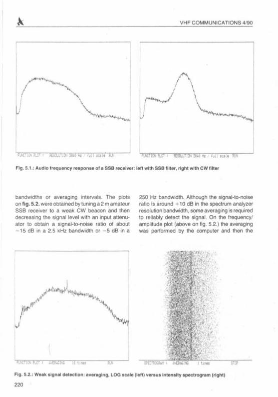
the mos l dlthe"lt tasks when build ing a sserlK*ver ,. 10 rTl8uur. the passband of !hecryslal Illtera used , reg81dleSl whether are lheyhOmebrew or commerCIally available Items. Toobtain a reliable result . a very I table sweepgenerator I. requi red In addltl()l"l to a storageoscilloacope due to the slow sweeping speedrequlfed. Alternatively . a FFTspectrum analyzercan be connected 10 lhe receiver alJdiO outpu'and a wideband noise source to 'he recewerInput (II the reeeiver own flOlse is 00' sutllelant ),Thanks lo the speed ot the FFTspect rum analySISthe resutl can be obta ined quiCker than With thesweep generator. alloWing raal·llma tuning 01thetrimme r. in and around the Crys tal III'e rs , Twotypica l resutls. plot,ed on a loga rithmiC amp llllJdescale. are shoWn on fig . 5.1.: a 2 kHz ssehtterabove and a 500 Hz CW Illter below. USIng FFTspectrum analyt,ls. the lfadeoU belween BCClJ
raq and speed is selected by choosi ng theaveraging lac1Ot' . How&vef . even With no averaging . the FFTanal YSiS WII' only prOVIde a f"IOIsypial while a 100 lasl sweep Q8r1el'a.or Will providea compIe 'ely distorted and thus useless resu l' ,
A FFT spectrum analyzer II able to reliablydetect very week eignell hidden in noise. lerbeyond what a human ear can do , since I'IS no tIImlled 10 certa in ' requeflC)' banda, resolution
219
I~
J
VHF COMMUNICATIONS 4/90
/\I \-......- \
\..--¥
., - , .. ., "'I, t
bandWIdthS or averagmg etetver• . The plclson 'Ig. 5.2. were Obtainedby tuning a2 m amaleursse rllC8iver 10 a weak CW beacon and thendecreUll'lg the Signal level with an Inpul altenuetor to obtain a SlQnal-to-nolse rene 01 aboUl- 15 dB In a 2,5 kHz bandwidth or - 5 dB in a
250 Hz bandwidth. Although lhe Slgnal·to-nolaerallOI' around +10 dB In !tie soeceum analyzerruolullon bandwidth, some averaging is required10 reliably detect lhe signal. On the Irequency!amplitude plot (above on Ilg, 5.2.) the averagingwal perlormed by the compuler and then the
(l":"", It.--, .000..;';: I t _
,,'.i'
'~..........~".......
'\ I'\' ''l
OJ.
220
VHF COMMUNICATIONS 4/iO
;
c
I1•
'.J'.~.
•!••••·•...~. -
•,..... -, .....~.. .........~
Sl'C"Y.Oo.t' ; , IX:
-•••,
'1eI.1
~._ ---_.. ' ·i-
I-_.._~ . .•..,l
result was pIoned , On Itle IntenSIty apectrog'am(belOw on fig. 5.2.) no ayeraglllg was performedby lhe compuler . A....raging is, howev er, per lormed by our eyes when ObServing the spectrograml
Eyen weaker Signals could be detected 8Ilherby increasing the Irequency resoluhon or byIncrealind the averaging lactor or both. Thepracheal Illmt is mainly imposed by the limerequired 100lhe tlgnai tobe available lor a rellabledetectlon . In a pract lC8lcommunica tIOnS systemthere are olher COIlslraints 100: receiver andtransmlner Irequency instability or phase noiseand propagation et1ac1s. The Fn spect rumanal yzer can solve the problem 01 Irequencyuncertainty, since i1allOws toObServealrequencyband 01 a lew kHz instaolaneouaty WIth a reI()lutlOn 01 5 10 10 Hz. The pNI" I'lCMS8 01 transminers and receIVers shoUld be mlmmized any·way. Unlortunately. lOme propagatIOn efleetsallO show up as phase or ampl itude noise ,especially in EME (moonbounce) communica·tiOns. These efleets are proportiOnal tothe earnerIrequency 10 maJOr advantage, 01 uSing FRtechnique ' lor EME communlC8tlOlls can only bee..pected on VHF and UHF Irequencie" Onthe.. Irequency bands FR SIgnal prOC8lllngmay deere8M the RF link performance ,..
QUlremenls by 1010 20 dB. l inee higher l igureswould result III usel.., cete ,a les . In any caM .
a communiCallonl protocol hal to be agreedupon belorellle.. technlQuel can be used :hand keyed CW il certainly nol a good choIctI lorcomputer processing
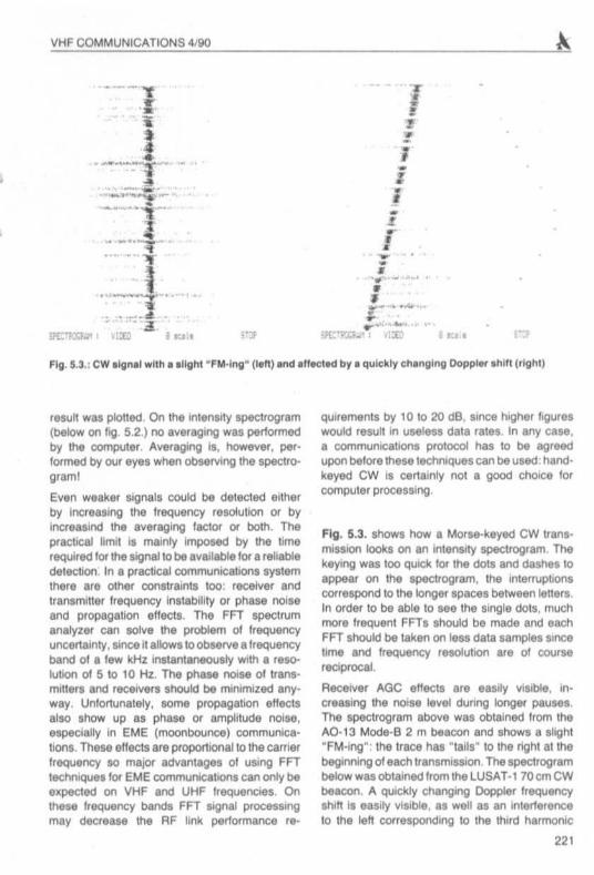
Fig . 5.3. shows how a Morse-keyed CW IranI milliOn Iooka on an inl8l'lSlty Ip8CIrogram. Thekeyrng was 100 QUICk 101 the dolS and dashes 10appear on the lpeclrog ram. the InterNpllOlllcor respond to Itle longe r spaces belween Ieners.In order to be able to Me the single dotl , muchmore Irequenl FRs should be made and eachFR lhould be laken on lell data sample, "neelime and Irequency re8OlUllOl'l are 01 coursereciprocal.
Receiver AGe efleets are easily visible , In·creallng the noise level during~ pauseS.The spect rogram above was obtained Irom IheA(). 13 Mode·B 2 m beacon and show, a llighl"FM·ing": the trace has "Ialll " 10 the righl al lhebeg.nning 01each Iransrmuion,The spect rogrambelow was obtained lrom the l USAT·l 70cmCWbeacon. A QUICkly Changll'ig Doppler Irequency&hit! Is eaSIly ViSible, as well as an interferenceto the len corresponding 10 the third harmonic
221
VHF COMMUNICATIO NS 4190
.'
01 the IIgnal . generated somewhera In the audioI lages of the SSB recei ver .
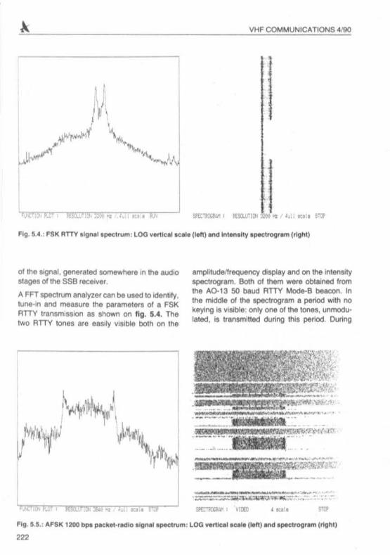
A FR speclrum a nalyze r can be used 10 Ideoilly,tune·in and measure the parame'~ 01 a FSKRTTY transmission as shown on fig . 5.... Thetwo RTTY tones are eaSily vIsible both on lhe
arnplilud&1requency display and on the intensllyspectrogram. BoIh 01 them were obtained l romthe A().1 3 50 baud RTTY Mode-B beacon. Inthe middle of the apeclrOgram a period WIth nokeying il viSible : only one of the tones, unmodu·laled. il transmitled during this period . During
=:o-=:- _ -_ .. ~.==-.--~"'\~ -.-:.. ~ :.-
.' il'Et1'IUtM" Vlllll
f lO· 5.1.: AfSK 1200. pac:~IIt, '.cl lo ""n.1apKtf\lm: l OG "'lHtlcal acale (t.n) and .pee1 rOV' ..... lrighll
222

•
VHF COMMUNICATIONS 4IiO
KWe ke'fW'Q me toni! 1J.cM become~ due10.... 50 bPI rroduIallOn~.
A FFT tpK1rUm MAfyZ_ eM tNni!(q be conSidlnd II an up-lO-dIite~ tor ....Q6d1aIhIonI<I RTTY,*~Uq 1ndIcRlr.BoIh toni!~ W 1M keying Ihft eMbequiddy and KCU'.llIty~, In 1lddrtIon,• FFT dtap&ay proYIdM intonnatlOn aboUt~d111Or11Dn (MIec1JW lung) or Inlel1erencn,Espeoally in 1M "fI... caM a FFT~y WillprowjIs IIOfne ,,"lui Inlonnallon aboUt ....
~.. 1o be ~en (noktI filler Uqtor• •&r'f'IPl-) and aboUt1hW~.
The paramet.... Of a FSK Of AfSK signal aramore OIf11cun 10 ldenlify it 1M dllta rllill II com palilble 10 lhe Ireq uency I Mt. III lhOwn onfig. $.5. 1200 bps PIIchHllcllo u... 1200 Hzand 2200 HZIonn.lhe I M III lheretora 1000 Hz.compalilble 10 IhII dllill rill. ol 1200 bps , Thespectrum ol IUCh II trllnsmillion III an a1moslconligUOUI I,eqU8nCYband wilh julla lew peak l ,that 00 nol nacellllrlly correspond 10 the lonefreque ncie l II' lhown on lig 5,5, llbova, TheInlensity spectrogram below showl lhe inler ·InInent nalura ol PKkIlt"adio 1ignaI1 ,~ 10IhIIIhor1 duratIOn of 1M pad!.atl, theit tPKIrumcouIcl neYIIl" be oblalned by II tcamng-Iac.vet
type IPIICtrum anatyzer.
A FFT IJ)eCIJUm .-,.zer CM be UMd as •valuable lutq .., tor PSK pedllIt·radlo communicabonl. Phue-lhIt1 keying II UMCl torN laln. pedlat.,adlo communicallOnS weeII aJlooNs • IongIIf~ range WIth.... NtTlII RF aqupmenl pettormInce, On !heoIhar '*'d, PSK and 0Ihel' oohatent~teQUll. ae:e:utala tunlng and goOd !f1lQUlll'\CYltabIIlty.
The spectrum ola 1200 bpi. pDlIt·radlO IransmiuQ'I trom 1M PACSAT·l NtalIrta lllhownonfig . U. The '*"~ shows .... spectrumdunng the tr~ ol rt.gt between 1MpDats, On thli '*" II III Hly 10 IdenI lty !heeam.r. IUrroundecl by~ apac«I at150 Hz. During the Iran llmu ion 01pac kel l ceotalnlrlg random dlltll lhe apactrum Iookl llimoelIIka pe rlect noise (Iig 5 6. below) lind II '1 mUChmor. dlfficul1 to Iclenltty lhe correct lUlling, Inlad . I llllighttorward PSK transmillion conllllrllvery bnle redundancy 1If1d thera lira no ,niduillcarn~ ai!her.
Some more redu ndancy ca n be roucee In IheA(). 13 400 bps BPSK Mode·S beacon Irllnl'mtIIion due 10 manchelllll C()dIng F"o!. 5.7.abova shows IN tPKIrum dunng IN IrllntmlNIOIl 01 the lining bylas (50 HI In be"","" Ihedlila !fames: thll repetItive penam gener.'as
223

VHF COMMUNICATIONS~
,'.
the many discrete spect ral lInes On the Intenartyspeclrogram onIlg. 5.7. below it is aasy to identify,he Singla data Irames and the Illling by1eperiodsIn-between them. Eyen dala !rames sometimescontain repetlllye patl ams causing discretespectral lines Inslda tha data frames . Regardless01 the modula tion data the signal spect rum hastwo main lObes caused by Ihe manchestercoding . The lalla r are potl tKJned symmelricallyaround the carrie r, IUppressed by this modulationtechmque
A FFT audIOspectrum analyzer Is uselulto chedIWEFAX and APT sateMe lignals and relatedIeceivlng eqUipment. USing a FFT spectrumanalyler importan t delalls olan unknown satellitetransmISSion, like lila' 01 • new satelillo, canoasl ly be determined . Further , Ih8 receivingequipment can be checked lor I COITOCl deemphasis ('0 ayold loosing geometrlca l resolutlon) and sources oleyentual interferences.
All this is easie r 10 deacrlbe on a well knowne~ample , Ilke lhe Meteosal WEFAX transmissionshown on fi g . 5,1. On the lTeqoency/amplitlJdepIol on fig . 5.8. abova the l lronges1 apecl raloomponenl il the 2400 Hz subcarfier. The 1Ub
22'
ca rner should be IUrTOUnded by symmetricallidebands il lhe deernphaals il properly ad1U11ed.The sidebands depend 01 (lOU1H on the picturecontent. The most notable dela il are lhe twosymmetrical peaks corraspondlng to the linesync 8040 Hz bursts. Thesehaye a rather roundedpeak, since their duration is yery shOrt: theirspect ral width Is inversely proportional 10 theirdur'liOn. The IntenSity spectrogr.m shown onIlg. 5 8. below IhowSlhat lhe sync burs1s appearin about every second FFT conversion. Also, theIP8CIrum cION 10 the 2 400 Hz subcanier alsoetIangeI wrlh the picture ~ne period. The annotatIOn IranSlT\llled at the end ol the picture IIwell viSIble . followed by the dlSCl'ele spedr.1linea 01 the ~50 Hz stop lone tasllng 5 seconds.What lotlows is Just part 011h8 spedrum ol a DCPrelransmlssion between two WEFAX pictur es.TheDCP flags creale twostrong discrete spectra lline Iraces on the spect rogram, interleayed wllhthree DCP delalrames visible on fig. 5.8, below .
The spectrum ol a NOAA APT IranamhlSion ,shownon fig . S .Q, Is a little morecompIell. Therestili a Itrong 2400 Hz subcarrier componenl, butthere are twodifferent lyTIC butsll ol 832 Hz and1040 Hz respectively. The sldeIobes geoerated

VHF COMMUNICATIONS 0&/90
..
, . ,.
I
....=•'Ig. 5.'.: MfTEOSAT WE'AIl'lgnal apec1ru," : LOQ lIertle.I .e.'" (Ieft) . nd Inl.... lty '1'I<1'oot.," (tigh l )
by both aync burStI are well viaabIe on fig. 5.9&boIIe . On the lntentrty lJ*1rOOratn on fig. 58be60w it II euy 10notICe that theN aync puiMIappear inl8fIUveCI In !he APT lignal . The r.mainlng spectrum 8110 ch8l"1Q81 with the ..me..-
. ~.
AlthOugh a FFT~ 8t\8Iyz..- II KtuIIIIya" audll).trequency 1_ ~I. II hII. many1l"It..-..tJng~11OnS ." the amateur-tlld!ofield . The aboY. a .ampIM were chosen ~t 10&how a lew poMIble applialbon. of • FFT apee.lrum analyzer and !he ma"y dlflefenl ways a
'1t.5.'.: HOAA·lO APT"''''lpeC1rvm : Loa ¥IftIC" eelItI l'-"l Iftd 1nt.,."'Y aptld"'9''''' (rlghl)
225
VHF COMMUNICATIONS 4/iOAL- --""====
FFT spectrum analyzer elln M uNd. Probablymost 0I1~ appIieIIllOnl .... yet to be dllCOVered ,Since FFT apeclrum analy... only becameI YIllable 10 amAleurs WIth recently developedlow COI1 and high~~and AID c:otWelf'l.,..
6.THE FFT SPECTRUM-ANALYZERPROGRAM FOR THE DSPCOMPUTER
The FFT algonItlm canbe mpIemeflled onalmostany digital c:ompuIer . rat'IgIAil !rom 8-bll vtdeOgame10)'110the .,~ end '..... lMIOlrarnM.The FFl a6gonhn '1IQUll''' vety 1m. "*""OI'y.tn:» \tie teeufta 01 • · bufterfly'" OI:*abOn ....stored In the Nl'M two rntmOfY IOCIiIIOnI wtlerlthe argumentI ... tp,.., trom Themor. thememory feQUltemerM ar. vwy low , n::ludlng",_ • bUtt., of the liz. 01 the IrlpUt ct-ta block
and anochef buffer of • tomIar Ill' 10 I'IClId 1M---01 COUfM the ••e<;ut l(lrl tImI ... depend on !hec:ompuIer UMd . ComputIOgI 1024-po1ntcomplexFFT on • 8-bot lTllCfocomputer ptogrammed In •
high-level 1an0u9 Ilk. BASIC WIll 'IQI•.m1
MYltfal lT'llnul" . ComputlrtgtheNme lQ24.poiotFFT on an IBM AT compatible eQUIPPed WIth1M mat'*NIbcal c:oproceuor and IllecullOg •
oompled program will , hi rllQUlfl ........... NCo
ones . A we!l·wr,nenm.chIne oodlI programtor.general-pufpOH 16-b11 microprocellOl' cancompute • 1024 ·polnl fFT In • lew hundredmllhMOOOdI uSing l8-bot Inleg_ ar ithmetiC'.FlO8lty, o.dlcated DSP rmcroproc-uorl ar.able 10 compute. 1024-pOinl FFT in lena ofmtlbMCOOda with the lop-o!·hne devicn 'e·quinng arew mlIIIHCOOdI,
A FFTspectrum·analyz.,program waswrmen lorthl asp compu'" publilhed In UKW·BE·RICHTENHF·COMMUNICATIQNS Thia comput8f Il'lCIudn a 8-b1! Ioganlhmic AID convert....InpUt port and a 512·pu:el by 258-1nI, 258-gey.IeYel YlCItlo d'~y . The MC680' 0 mlCfoptoeee
m
IIOl' UMd In !his computer II .. 10 comput.a 102"-point compIel FFT Itl eboul 150 mllltaec:onds. Considering ~t some CPU bme isrequlr~ lor ot,,* func1lons too , ~ke inlerruplhandling or d1sp1.1y upa.t., the m(uum"m sampling frequency tor~ bul non-G't'el".
lapping FFTs WIthout~ In'f JnPUl a.!IIIS abOul 8 kHz ThIs 1IQur. malc:hel v«'f weithe pertormance 01 the~filler In front of the AID /Xll"IV«Ier U well .. theaudio bMdwidth av..aablil !rOm s~.
IlOnS oram.leurt~.
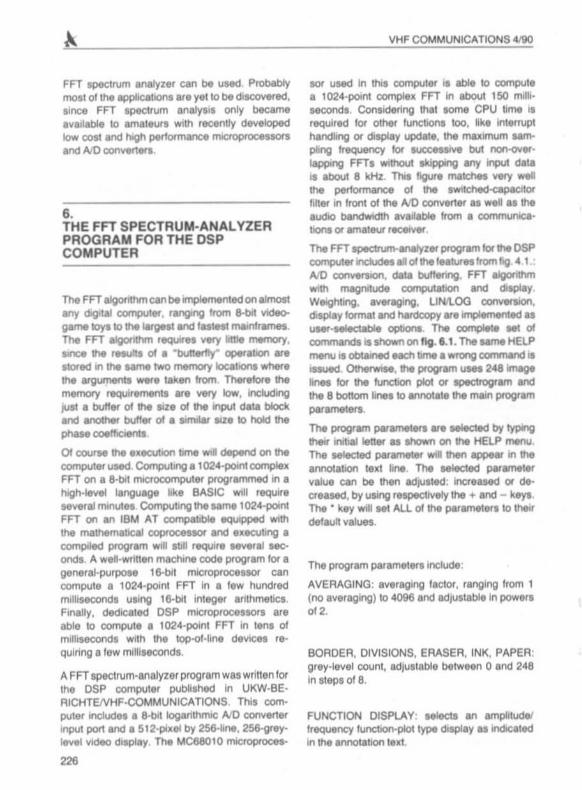
The FFTtpIICtfum-.wy:er progtam kif the DSPcomputer indudM.. of !he IMIUr.. tromflg.4 1AID 0ClI"IVetSI0fl . dWI~. FFT -'gOl ,ItmW11tt FNgtll!Ude CQI'l'IPU!IIbOn and dIsPIy,WlIIghbng , aV9tag.ng. UNIlOO c:onverslon .display klfmI,t sncI t\atdcopy ....~_U
...... ..111::1.. QClIIJOtW; . The~ ... ofCQI'IVfIIt'dS is shown on"e.1.1.n. sameHELPmenu .. CIbCalNd NCtl time a Wfong commrc:l ..-...ct. ()ttwrwIM. the progtwn lINt 2~~IineI tor the luncbon plot or spectrogram and!he 8 bottom Ilnlts 10 arn:Jtat. the main progtam,.-The ptOgtAmpar~.... M6eded by IyplngtheW irwbIl len.- u Ihown on .... HELP tNt'IU .
The MI«1ecI paramew WII then II(:lpNJ in theamoIabon 'ad line . The MleCtecl parametervalue can be then adJUst~ : inCf.aMd (It decreuecl, by uSing lespec1Jvely the + and - keys ,The • key ...... set AU of the parameters 10~delaunvalues,
The program paramel8fS incluoe:
AVERAGING : a....nlg,ng factor. rang ing Irom 1(no a..,., aging ) to "096 and adjustable In pow."012 .
BORDER, DIVISIONS. ERASER. INK, PAPER'gr.y·Iev.1 count, KI,uatabie betweeo 0 and 248in s'eps of 8 ,
FUNCTION DISPlAY: MIects an amplitude'Irequency function-plot typrI dlsplay u Indal~
III the annot.bOn Iel1_

VHF COMMUNICATlONS.vao
. 00 IPt'..l'£N"CI Cl:r1Wa OIl
1::' ...\ _...
I•••
Fig . fI.1.: H. lp INnu oflh. FFT ' pKln.lm-. n. ly..,prog"m . howln'll.U lmp!tmtnlotdco mm.nd.
GAIN: adjusts !he gain between !he AID ceoverlet output and FFT input to incr. ase !hedynamIC ' ange WIlh Iow-level lignals _ Usuallyset to 1 to pr....ent saturahon.
HARDCOPV: each time H Is deproued. a hard ·copy lile PL.OT ,DAT II crealed . The format ilselected to be understood by moel dot-malri~
and laser prlnlerl , Since these prlnters can nolprint grey levels, the IrBl hold between blackand white Is sel lo.grey·Ieve1count 01 127/1281
OVERLAP: twlleoel the ov.rlap (SO ""I optIOnON or OFF (Ioggle operatIOn). When ON. theoverlap optIOn is indICated by en ·0· In theannola tlOnle)(\.
RESOlUTION : Seledl lhe sampling trequencyand lher. lore lhe lull-scala trequency span orresolution balween 301 and 8400 Hz by se"mgme sampling-lrequency divkler modulo.
SPECTROGRAM DISPLAV: selects an intenSityspectrogram type dIsplay. as indlCBled In the. nnota Hon ted.
TRIGGER : starts or Slopt (toggle operahonllhe operahon of the spectrum an.lyzel . Th..I8luI RUN or STOPil IMalad in the annal.tlOnl.~t IN !HE STOP mode. the display il "l l ozen" _
....~ . ,,-,, ...... ' ," ' ~IlIU''''''
Fig . 4502 .: TP 3040 Input nn ... paHbaoncl flen ) MMI MK 1 116 " 0 con'llll"t... 1101.. w l1h _ Input .Ig...,. (righl)

VIDEO : MlectI the Ytdeo gaon aft., the FFT~Ithm ., the UN mode. The row.st MttlngNlects a tOO Ytdeo~ (dillaunl,
WEIGHTING ~ the r~
~ opIIOn ON Ot OFFj~ operallOn).When ON. ....~ opIIOn • 1ndIeI1" bya "W" ., IN W1r'lCUbOn IlIn
The per1ormIlnc::e ollhll FFT spectrum anatyz., IIof COUrM limit" by the analog harcJwar. UNdInpUt bandpass IIlterW1dAiO~er. Fig. 1.2..oov. ahowI the pusband 01 the InpU! lIlter,Obl..oed WIth the .-me apectrum aM!yzer bylimply connectll"lg a wideband ro..~ tolhe input. The dynamic ranQe of the 8-bI1loganthrTIIC AiO conv8f1ltf u.ed .. only abou1 40 dB due10 quanh'lIhon noise The performance of lhe.pectrum analyzer i. however beller : in manyprachcal case. lhe display dynamic ranger.achn 60 dB llnee lhe q....ntl.atlOn I"IOlHuMJalIy appear...~ notN.
The InpUl~ fill., and NO CO'\
-...rt., own roM II wei Ylllbleon flg 1 .2. below.Usang a IOganthmlc amplitude dalplay the QUWltlsatlOn 'lept beeome very large at low ...1........ In the Loo vertaI mode, IN lui ICaIeampIltude rangt II 15 bot. Ot go ee The till·lefenc:e tlefvwMn c;:cuQ I and 2~ ......lor. correlPCJf'Cl 10 the tilrrer.nc. betweencountI 1&384 and 32768 on .lOO 1C8le, how ever Ifl the lormet cue trler, ar. no addIbonalcounts poAIbIe betwMn 1 and 2 rnulllng .,r~allVety large "steps· on the Oisplay.
W,th a 10 MHz CPU clock, Ihe Fn~ana/yl... program • able 10 opel'" wrtt1 aumplIng frequency of aboul 8 kHz: (rHOlutlon4 kHz) on conbgUOUa but~ dataThe input dala butter r(IU1lne it dnlgoed to skipdata block. aulomahcally II the CP U ,. unableto lurther prcceee Ihem in reer lima, like In thacase of a higher sampling lrequency or overlappng FFTa, Sometimn it's very UHlul to beIIbIe to aperate In these conclltlOM even II aomedata is k»I , On Ihe ethel' hand, an aNIog lean
rlII"Ig-r~ type SPectrum an&lyz.,. uauaJlydrlCanla over 99 % oIlhe 1fll0000tJon cont8IrIedlfllhe Input~!
2:18
VHF COMMUNICATIONS "'W
The FFT program ndudM a 1024-p:wr1 c:omplrallFFT aIgonU'Im. The algorithm II UNd 10 processtwo~ "" 011024~ InpJIwmpIn. The rell.lftl 01 the Fn ar. then separated UIIng !he Founer Ifansform Iynwnevy laws"10 two indepWldenI 512-pQlf1( aignIII spectraThe phue r.tonnabon Ie re,acsed and the~ludltI.e~ UWIg a QUic:k approUNtlOntor the tqUar. rool. The U"'\,OO converston •obtaInltd wrtt1 • klokup.t8b18 Ilgonthm to aYOIdthe ....... .,..,. log h.n:liOn .
The display routine lOCludeI automahC ~mlbng
rl !he magrwlude allceeda the lop on a functionpial Ot the nWlllTlUlTI brightneat on an irIlltOlllyspecl1ogram , Hardc:JoPln of !he oomputltf lICfeenin the vanou. modes are UNd thrOUghoul thll
"'".
The FFT spectrum-analyzer program i. wnnenpartially In the MC680I O machine code andpartially in the DSP computer hlgholevel language,The comment.cllOU~ program i. about15 kiloby\el long wtvIe the compIIad programrequlrn about 47 kbytn. ThIa Is Ktu8Ity ....than moat CICh.- DSP programs lhanks to thecompac1nnt and lOw memory requwllfNOts 01the FFT aIgonthm, 01 COUrM the FFT programcan run lfl multitUll with other programs thaido notUH the aamepenpher.... llk.1he TRACK,,"",om
Future \W"-- to the FFT apectrum-anatyz.,program ehoU6d rdude '" C8PM*Y 10 ad,ult1M I&Z. 01' the FFT (number 01ponti) ICCOfdlrlg10 the~ 01 the mNeUfemenl: aomeproblems (qudlly Changing Ilg08III requM"
.... than 1024 poInlS wtvIe othetI require ahighel' rnolubon and thua men than 1024 pclIr'Itt
The 10241lO1fll Fn II~ a good comproIT1lM tor ma.l meuuremenu.
Finally, IIIsI'lOptld that lhIa artICle wiM encourageamateura 10 UN the FFT algonthm and FFTspectrum anaIY' il , sece the lane, can easily beImplemented on the descrlbed DSP computerand on many other computetl .. well. PresentlyFFT spectrum anatyM it only available on lop0I.Jrne prolnllonal 1nItru",,"lIitO'l and !hereuon tor thIa Ieprobabty the poor uncterstandlngof IhII newt«:Mq.wby !he INPflly 01apectruma~l"'~

VHF COMMUNICATIONS 4190
7.LITERATURE
(1) VKlmar , M., YT3 MV:Dig ital Signal Procesaing Techrwques lorRadIOAmat eursTheoratieal Par1VHF COM MUN ICATIONS Vol. 20,Ed , 211988. P. 78·97
Par1 2: Design of a DSP Com putar lor RadiOAmaleu r AppIic.8tlonlVHF COMMUNICATIONS Vol . 21 ,
Ed. 111989. P. 2 ·2"
Par13 : eonslrucllOl'1 and Use 01the DSPCom puterVHF COMMUNICATIONS Vol. 21,Ed 211989, P. 7"-94
Par1"a : AppIlcallon SoftwareVHF COMMUNICATIONS Vol , 21,Ed , 3'1989, P. 130 - 137
Par14b : Apphca.11OI'l SollwareVHF COMMUNICATIONS Vol . 21,Ed 4/1989, P. 216 - 227
Amaleu r·R adiOApp lIcations 01Ihe FaslFourier Translorm - Pal'! 2aVHF COMMUNICATIONS Vol . 22.Ed , 3' 1990. P. 130 ·138
50 n Coaxial Relays
"~ ex 120PArt.No .: 0500 OM 43.50
l uillble lor PCB ln" I IIIIIOftFreq range 500 "'HI . Pme. 150 W: onMf1IOflloM< 0 2 d8l 1 QHl : lIoIa llon .O dB/I GHl ; SWA l W1 OHl : 11• IIIVOC; ' 20 mAl13 11 VOC
ex 520 0Art.No .: 0503 OM 99.50
3 . N' lOCke ll, with lrM-ConlK1 1I'OUncll"'llFfIq_range 2 5 OHI : Pml~ 300 Wil OHI . .......toon 10II 0 2 dBll5 GHI : *"1l00n 50 dB/ l OHI.SWR 1,1/1 OHI; 11 .1 5 VDC: 160 mAt1 2 VDC
ex 600 NArt.No .: 05004 OM 89.-
ex 140 0Art .No. : 0501 OM 59.50
:2 . cable COftnec:t. RGSIU . 1 N·.cN:ketFleq rlnge:2,5GHI (mi x). Pm.. 2OQ W'500 MHl :InNflIOn loll 02 d8l 2 5 GHI . tIOll llon . 0 d811 OHl : SWA 1,W1 GHl : 1I • ' 11 VOC: 120 mA!1311 VOC
I\•
3 . N-toekli 'Freq . lange 1 5 OHI . Pm,. llOO WI500 "'HI ; In
M rtoon lop 0.2 d8lSOO MHz; isolatoon 35 d8l5OOMHI : SWR 1.1/500 MHI ; 10 ·1 5 VOC: teo mA!
"VOC
•ex 230OM 82.50" Ar1.No .: 0502
• ex 600 NeArt.No. : 0505 OM 84.
3 . u ble connect. RQ 51. 1 N..cN:ket3 . SHC tackell Freq rl nge 1 OHI : Pm.. 600 WI500 MHI : In·F,eq rlnge 1 5 OHI : Pml~ 300 W/500 "'HI ; InJe" H rtoon loll 02 dB/500 MHl : 'solation 35 dB!500toon l0li 0 2dS,500 MHI .,IOlIl00n30dBi500 MHI : M~, SWA 1 1/500 MH, : 10 · 15 VOC: leo mAlSWR 111500 "'HI : 11 - 15 VOC: leo mA!12 VOC 12 VOC
k IUOOJi 'berichte T. a ,"aoQHG •Jahn,• . 14 • Po,.acl! BO' 0·B523 aa,.,sqorlTel. 09133·47-0 · TelelalC 09133 -4747 · PSchKlo Nurnberg 30455·858
229


![Amateur Operato Advanced - Australian Maritime College · Amateur Operato Advanced Syllabus and Examination. The Amateur Licence (amateur advanced station) [the Advanced Amateur Licence]](https://img.pdfslide.us/doc/110x75/5f072ed67e708231d41bb822/amateur-operato-advanced-australian-maritime-college-amateur-operato-advanced.jpg)