Embed Size (px)
Citation preview

Revision Date: February 3, 2020 P a g e | 1 of 40
Amateur Radio
Technician Class License
Study Guide
(For use July 1, 2018 to June 30, 2022)
Compliments of:
Earl Paazig
W8BR
This document is based upon the publicly released question pool and was
developed for not-for-profit educational use only and may be used and
distributed accordingly.
Study Guide is based upon the FCC Exam Element 2 Question Pool for Technician
Class, effective 7/01/2018-6/30/2022 with added and revised material.
Revision Date: February 3, 2020 P a g e | 2 of 40
Foreword
This document is based upon the publicly available question pool. The format
intent is to retain as much of the original words from the question pool as
possible to leverage familiarization in the learning and memory process.
Specific references to Part 97 are retained throughout. The 18 terms most
frequently used in the text are:
amateur current power
antenna electrical radio
band FCC repeater
circuit frequency signals
communication license station
control operator voltage
The author’s hope is that this document might be useful as a resource in
studying for the Element 2, Technician Class License Amateur Radio Exam.
In order to pass the exam, you must correctly answer 26 of 35 questions. The
exam is constructed from the sections of the Question Pool in manner consistent
with the following table:
Sub-element Exam Questions
T1 - FCC Rules 6
T2 - Operating Procedures 3
T3 - Radio wave characteristics 3
T4 - Amateur radio practices 2
T5 - Electrical principles 4
T6 - Electrical components 4
T7 - Station equipment 4
T8 - Modulation modes 4
T9 – Antennas and feedlines 2
T0 – Electrical Safety 3
Total 35
Revision Date: February 3, 2020 P a g e | 3 of 40
Table of Contents
ELEMENT 2 SUBELEMENT Page #
T1 - FCC Rules ................................................. 4
T2 - Operating Procedures ....................................... 11
T3 - Radio wave characteristics ................................. 15
T4 - Amateur radio practices and station set-up ................. 18
T5 - Electrical principles ...................................... 20
T6 - Electrical components ...................................... 24
T7 - Station equipment .......................................... 28
T8 - Modulation modes ........................................... 32
T9 – Antennas and feedlines ..................................... 36
T0 – Electrical Safety, antenna installation, RF hazards ........ 38

Revision Date: February 3, 2020 P a g e | 4 of 40
SUBELEMENT T1 – FCC Rules, descriptions, and definitions for the Amateur Radio
Service, operator and station license responsibilities – [6 Exam Questions - 6
Groups]
T1A - Amateur Radio Service
Purpose and permissible use of the Amateur Radio Service
A purpose of the Amateur Radio Service as stated in the FCC rules and regulations is advancing skills in the technical and communication phases
of the radio art. [97.1]
The FCC regulates and enforces the rules for the Amateur Radio Service in the United States. [97.1]
Operator/primary station license grant
One operator/primary station license grant may be held by any one person. [97.5(b)(1)]
The proof of possession of an FCC-issued operator/primary license grant is when the control operator's operator/primary station license appears in
the FCC ULS consolidated licensee database. [97.7]
Meanings of basic terms used in FCC rules
The FCC Part 97 definition of a beacon is an amateur station transmitting communications for the purposes of observing propagation or related
experimental activities. [97.3(a)(9)]
The FCC Part 97 definition of a space station is an amateur station located more than 50 km above the Earth's surface. [97.3(a)(41)]
Radio Amateur Radio Emergency Service (RACES) rules
The Radio Amateur Civil Emergency Service (RACES) is described by the following:
o A radio service using amateur frequencies for emergency management or
civil defense communications
o A radio service using amateur stations for emergency management or
civil defense communications
o An emergency service using amateur operators certified by a civil
defense organization as being enrolled in that organization
(All of these choices are correct) [97.3(a)(38), 97.407]
Interference
At no time is willful interference to other amateur radio stations permitted. [97.101 (d)]
Phonetics
The use of a phonetic alphabet for station identification in the Amateur Radio Service is encouraged by the FCC rules. [97.119(b)(2)]
Revision Date: February 3, 2020 P a g e | 5 of 40
Frequency Coordinator
A Volunteer Frequency Coordinator, recognized by local amateurs, recommends transmit/receive channels and other parameters for auxiliary
and repeater stations. [97.3(a)(22)]
A Frequency Coordinator is selected by amateur operators in a local or regional area whose stations are eligible to be repeater or auxiliary
stations. [97.3(a)(22)]
T1B - Authorized frequencies
Frequency allocations, Restricted sub-bands, and Emission modes
The frequency, 52.525 MHz is within the 6-meter amateur band. [97.301(a)]
You are using the 2-meter band when your station is transmitting on 146.52 MHz. [97.301(a)]
The limitation for emissions on the frequencies between 219 and 220 MHz is Fixed digital message forwarding systems only. [97.305(c)]
The 50.0 MHz to 50.1 MHz and 144.0 MHz to 144.1 MHz, VHF/UHF frequency ranges are limited to CW only. [97.305(a), (c)]
Only the 10-meter HF band has frequencies available to the Technician class operator for RTTY and data transmissions. [97.301(e), 97.305(c)]
Within the HF bands, a Technician class operator has phone privileges in the 10-meter band only. [97.301(e), 97.305]
Transmissions near band edges
You should not set your transmit frequency to be exactly at the edge of an amateur band or sub-band for the following reasons:
o To allow for calibration error in the transmitter frequency display
o So that modulation sidebands do not extend beyond the band edge
o To allow for transmitter frequency drift
(All of these choices are correct) [97.101(a), 97.301(a-e)]
Spectrum sharing
A result of the fact that the Amateur Radio Service is secondary in all or portions of some amateur bands (such as portions of the 70 cm band) means
U.S. amateurs may find non-amateur stations in those portions, and must
avoid interfering with them. [97.303]
Contacting the International Space Station
Any amateur station licensee holding a Technician or higher-class license may make contact with an amateur radio station on the International Space
Station (ISS) using 2 meter and 70 cm band frequencies. [97.301,
97.207(c)]
International Telecommunications Union (ITU)
The International Telecommunications Union (ITU) is the United Nations agency for information and communication technology issues.
Revision Date: February 3, 2020 P a g e | 6 of 40
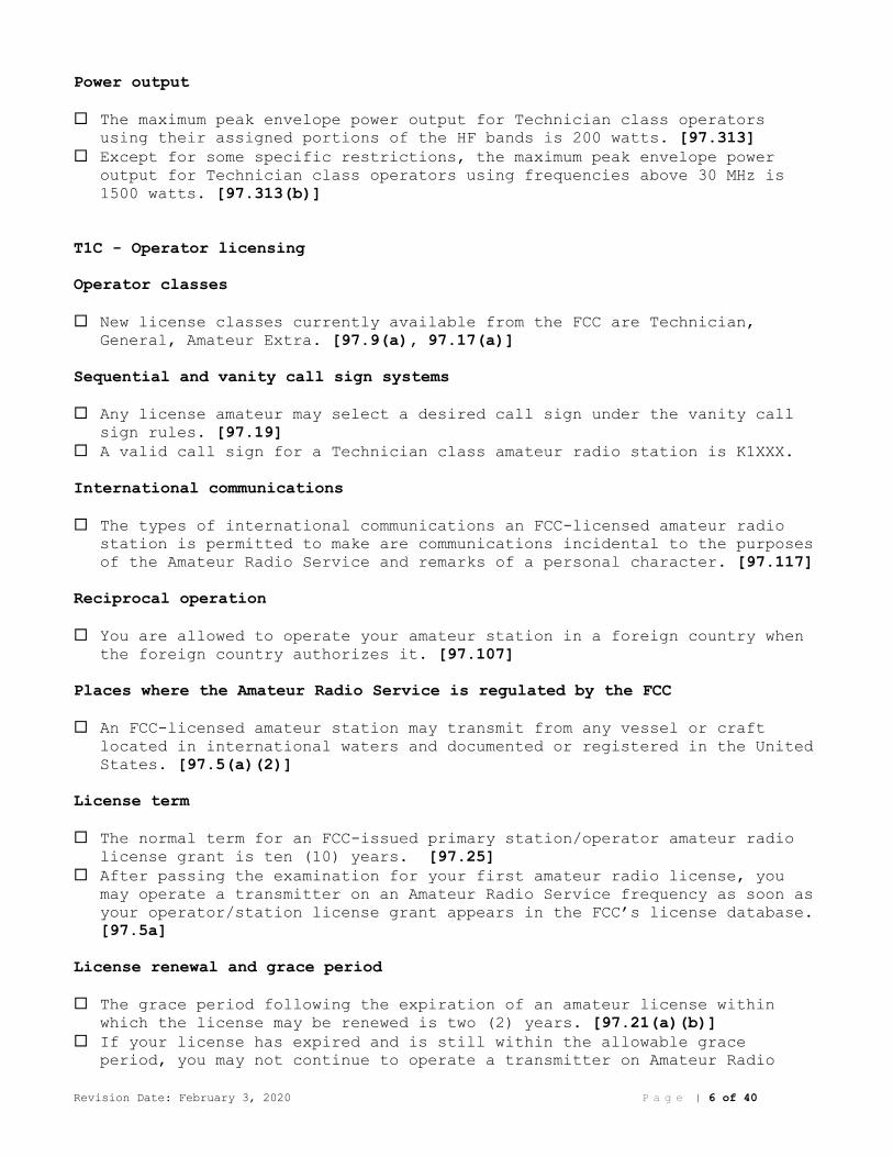
Power output
The maximum peak envelope power output for Technician class operators using their assigned portions of the HF bands is 200 watts. [97.313]
Except for some specific restrictions, the maximum peak envelope power output for Technician class operators using frequencies above 30 MHz is
1500 watts. [97.313(b)]
T1C - Operator licensing
Operator classes
New license classes currently available from the FCC are Technician, General, Amateur Extra. [97.9(a), 97.17(a)]
Sequential and vanity call sign systems
Any license amateur may select a desired call sign under the vanity call sign rules. [97.19]
A valid call sign for a Technician class amateur radio station is K1XXX.
International communications
The types of international communications an FCC-licensed amateur radio station is permitted to make are communications incidental to the purposes
of the Amateur Radio Service and remarks of a personal character. [97.117]
Reciprocal operation
You are allowed to operate your amateur station in a foreign country when the foreign country authorizes it. [97.107]
Places where the Amateur Radio Service is regulated by the FCC
An FCC-licensed amateur station may transmit from any vessel or craft located in international waters and documented or registered in the United
States. [97.5(a)(2)]
License term
The normal term for an FCC-issued primary station/operator amateur radio license grant is ten (10) years. [97.25]
After passing the examination for your first amateur radio license, you may operate a transmitter on an Amateur Radio Service frequency as soon as
your operator/station license grant appears in the FCC’s license database.
[97.5a]
License renewal and grace period
The grace period following the expiration of an amateur license within which the license may be renewed is two (2) years. [97.21(a)(b)]
If your license has expired and is still within the allowable grace period, you may not continue to operate a transmitter on Amateur Radio
Revision Date: February 3, 2020 P a g e | 7 of 40
Service frequencies. Transmitting is not allowed until the FCC license
database shows that the license has been renewed. [97.21(b)]
Name and address on FCC license database
Revocation of the station license or suspension of the operator license may be the result when correspondence from the FCC is returned as
undeliverable because the grantee failed to provide and maintain a correct
mailing address with the FCC. [97.23]
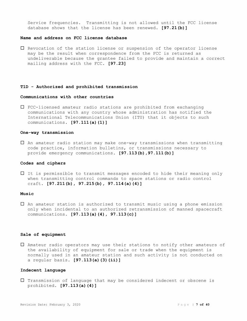
T1D - Authorized and prohibited transmission
Communications with other countries
FCC-licensed amateur radio stations are prohibited from exchanging communications with any country whose administration has notified the
International Telecommunications Union (ITU) that it objects to such
communications. [97.111(a)(1)]
One-way transmission
An amateur radio station may make one-way transmissions when transmitting code practice, information bulletins, or transmissions necessary to
provide emergency communications. [97.113(b),97.111(b)]
Codes and ciphers
It is permissible to transmit messages encoded to hide their meaning only when transmitting control commands to space stations or radio control
craft. [97.211(b), 97.215(b), 97.114(a)(4)]
Music
An amateur station is authorized to transmit music using a phone emission only when incidental to an authorized retransmission of manned spacecraft
communications. [97.113(a)(4), 97.113(c)]
Sale of equipment
Amateur radio operators may use their stations to notify other amateurs of the availability of equipment for sale or trade when the equipment is
normally used in an amateur station and such activity is not conducted on
a regular basis. [97.113(a)(3)(ii)]
Indecent language
Transmission of language that may be considered indecent or obscene is prohibited. [97.113(a)(4)]

Revision Date: February 3, 2020 P a g e | 8 of 40
Retransmission of other amateur signals
Repeater, auxiliary, or space stations are types of amateur stations that can automatically retransmit the signals of other amateur station.
[97.113(d)]
Compensation for use of station
When the communication is incidental to classroom instruction at an educational institution the control operator of an amateur station may
receive compensation for operating that station. [97.113(a)(3)(iii)]
Exchange of information with other services
Amateur stations may be authorized to transmit signals related to broadcasting, program production, or news gathering, assuming no other
means is available, only where such communications directly relate to the
immediate safety of human life or protection of property. [97.113(5)(b)]
The term broadcasting in the FCC rules for the Amateur Radio Service is defined as transmissions intended for reception by the general public.
[97.3(a)(10)]
Unidentified transmissions
An amateur station may transmit without on-the-air identification when transmitting signals to control model craft. [97.119(a)]
T1E - Control operator and control types
Control operator required
An amateur station is never permitted to transmit without a control operator. [97.7(a)]
Eligibility
Any amateur whose license privileges allow them to transmit on the satellite uplink frequency may be the control operator of a station
communicating through an amateur satellite or space station. [97.301,
97.207(c)]
Designation of control operator
The station licensee must designate the station control operator. [97.103(b)]
Control point and location of control operator
An amateur station control point is the location at which the control operator function is performed. [97.3(a)(14)]

Revision Date: February 3, 2020 P a g e | 9 of 40
Privileges and duties
The class of operator license held by the control operator determines the transmitting privileges of an amateur station. [97.103(b)]
At no time, may a Technician class licensee be the control operator of a station operating in an exclusive Amateur Extra class operator segment of
the amateur bands. [97.301]
When the control operator is not the station licensee, the control operator and the station licensee are equally responsible for the proper
operation of the station. [97.103(a)]
The FCC presumes the station licensee is the control operator of an amateur station, unless documentation to the contrary is in the station
records. [97.103(a)]
Local, automatic and remote control
Repeater operation is an example of automatic control. [97.3(a)(6), 97.205(d)]
Operating the station over the internet is an example of remote control as defined in Part 97. [97.3(a)(39)]
The following is true of remote-control operation: o The control operator must be at the control point
o A control operator is required at all times
o The control operator indirectly manipulates the controls
o (All of these choices are correct) [97.109(c)]
T1F - Station identification
FCC inspection
The station licensee must make the station and its records available for FCC inspection after failing to comply with an FCC notice of violation.
[97.103(c)]
Club stations
A requirement for the issuance of a club station license grant is the club must have at least four members. [97.5(b)(2)]
Station identification
An amateur station is required to transmit its assigned call sign at least every 10 minutes during and at the end of a communication. [97.119(a)]
The English language is an acceptable language to use for station identification when operating in a phone sub-band. [97.119(b)(2)]
Method of call sign identification required for a station transmitting phone signals are sending the call sign using a CW or phone emission.
[97.119(b)(2)]
When using tactical identifiers such as “Race Headquarters” during a community service net operation, you must transmit the station’s FCC-
Revision Date: February 3, 2020 P a g e | 10 of 40
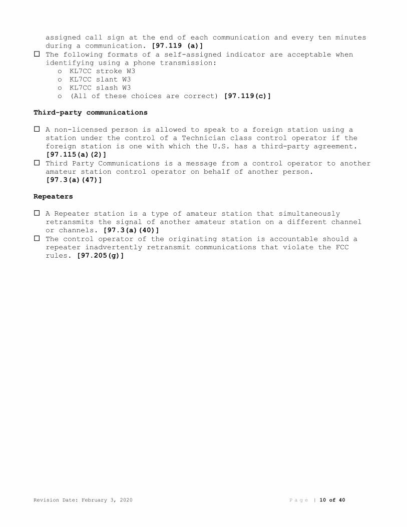
assigned call sign at the end of each communication and every ten minutes
during a communication. [97.119 (a)]
The following formats of a self-assigned indicator are acceptable when identifying using a phone transmission:
o KL7CC stroke W3
o KL7CC slant W3
o KL7CC slash W3
o (All of these choices are correct) [97.119(c)]
Third-party communications
A non-licensed person is allowed to speak to a foreign station using a station under the control of a Technician class control operator if the
foreign station is one with which the U.S. has a third-party agreement.
[97.115(a)(2)]
Third Party Communications is a message from a control operator to another amateur station control operator on behalf of another person.
[97.3(a)(47)]
Repeaters
A Repeater station is a type of amateur station that simultaneously retransmits the signal of another amateur station on a different channel
or channels. [97.3(a)(40)]
The control operator of the originating station is accountable should a repeater inadvertently retransmit communications that violate the FCC
rules. [97.205(g)]
Revision Date: February 3, 2020 P a g e | 11 of 40
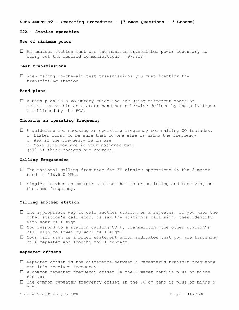
SUBELEMENT T2 - Operating Procedures - [3 Exam Questions - 3 Groups]
T2A - Station operation
Use of minimum power
An amateur station must use the minimum transmitter power necessary to carry out the desired communications. [97.313]
Test transmissions
When making on-the-air test transmissions you must identify the transmitting station.
Band plans
A band plan is a voluntary guideline for using different modes or activities within an amateur band not otherwise defined by the privileges
established by the FCC.
Choosing an operating frequency
A guideline for choosing an operating frequency for calling CQ includes: o Listen first to be sure that no one else is using the frequency
o Ask if the frequency is in use
o Make sure you are in your assigned band
(All of these choices are correct)
Calling frequencies
The national calling frequency for FM simplex operations in the 2-meter band is 146.520 MHz.
Simplex is when an amateur station that is transmitting and receiving on the same frequency.
Calling another station
The appropriate way to call another station on a repeater, if you know the other station's call sign, is say the station's call sign, then identify
with your call sign.
You respond to a station calling CQ by transmitting the other station’s call sign followed by your call sign.
Your call sign is a brief statement which indicates that you are listening on a repeater and looking for a contact.
Repeater offsets
Repeater offset is the difference between a repeater’s transmit frequency and it’s received frequency.
A common repeater frequency offset in the 2-meter band is plus or minus 600 kHz.
The common repeater frequency offset in the 70 cm band is plus or minus 5 MHz.
Revision Date: February 3, 2020 P a g e | 12 of 40
Procedural signs
The meaning of the procedural signal “CQ” is calling any station.
T2B – VHF/UHF operating practices
Frequency Splits and shifts
The most common use of the “reverse split” function of a VHF/UHF transceiver is to listen on a repeater’s input frequency.
Continuous Tone-Coded Squelch System (CTCSS)
CTCSS is the term describing the use of a sub-audible tone transmitted along with normal voice audio to open the squelch of a receiver.
The following could be reasons you are unable to access a repeater whose output you can hear:
o Improper transceiver offset
o The repeater may require a proper CTCSS tone from your transceiver
o The repeater may require a proper DCS tone from your transceiver
(All of these choices are correct)
Carrier Squelch
If a station is not strong enough to keep a repeater’s receiver squelch open you might receive the station’s signal by listening on the repeater
input frequency.
Over deviation
If a repeater user says your transmissions are breaking up on voice peaks, you are talking too loudly.
Dual-tone multi-frequency (DTMF)
DTMF tones are used to control repeaters linked by the Internet Relay Linking Project (IRLP) protocol.
Digital Mobile Radio (DMR) Talkgroup
You can join a digital repeater’s “talk group” by programming your radio with the group’s ID or code.
A “talk group” on a DMR digital repeater is a way for groups of users to share a channel at different times without being heard by other users on
the channel.

Revision Date: February 3, 2020 P a g e | 13 of 40
Operational problem resolution
When two stations are transmitting on the same frequency interfere with each other common courtesy should prevail, but no one has absolute right
to an amateur frequency.
Q signals
QRM is a Q signal indicating that you are receiving interference from other stations.
QSY is a Q signal indicating that you are changing frequency.
Simplex
Simplex channels are designated in the VHF/UHF band plans so that stations within mutual communications range can communicate without tying up a
repeater.
SSB phone
SSB phone may be used in at least some portion of all the amateur bands above 50 MHz.
FM repeater
A linked repeater network is a network of repeaters where signals received by one repeater are repeated by all the repeaters.
T2C – Public service
Applicability of FCC rules
FCC rules always apply to the operation of an amateur station. [97.103(a)]
Operating restrictions during emergencies
Amateur station control operators are permitted to operate outside the frequency privileges of their license class only if necessary, in
situations involving the immediate safety of human life or protection of
property.
RACES and ARES
Both Radio Amateur Civil Emergency Service (RACES) and Amateur Radio Emergency Service (ARES) organizations may provide communications during
emergencies.
The ARES is licensed amateurs who have voluntarily registered their qualifications and equipment for communications duty in the public
service.

Revision Date: February 3, 2020 P a g e | 14 of 40
Phonetic Alphabet
When using voice modes spell the words using a standard phonetic alphabet to ensure that voice messages containing unusual words are received
correctly.
Net and traffic procedures
The term "NCS" used in net operation is the Net Control Station (NCS).
The term “traffic” in net operation refers to formal messages exchanged by net stations.
An accepted practice to get the immediate attention of a net control station when reporting an emergency is to begin your transmission by
saying "Priority" or "Emergency" followed by your call sign.
An accepted practice for an amateur operator who has checked into a net is to remain on frequency without transmitting until asked to do so by the
net control station.
The information needed to track the message is contained in the preamble of a formal traffic message.
The term “check,” in reference to a formal traffic message, is the number of words or word equivalents in the text portion of the message.
A characteristic of good traffic handling is passing messages exactly as received.
Revision Date: February 3, 2020 P a g e | 15 of 40
SUBELEMENT T3 – Radio wave characteristics: properties of radio waves;
propagation modes – [3 Exam Questions - 3 Groups]
T3A - Radio wave characteristics
Multipath and Fading
If another operator reports that your station’s 2-meter signals were strong just a moment ago, but now they are weak or distorted, try moving a
few feet or changing the direction of your antenna if possible, as
reflections may be causing multi-path distortion.
A likely cause of irregular fading of signals received by ionospheric reflection is random combining of signals arriving via different paths.
Error rates are likely to increase if data signals arrive via multiple paths.
Wavelength vs absorption
The range of VHF and UHF signals be greater in the winter due to less absorption by vegetation.
Fog and light rain will have little effect on radio range on the 10 meter and 6-meter bands.
Precipitation would decrease range at microwave frequencies.
Antenna orientation
Horizontal antenna polarization is normally used for long-distance weak-signal CW and SSB contacts using the VHF and UHF bands.
Polarization
If the antennas at opposite ends of a VHF or UHF line of sight radio link are not using the same polarization the signals could be significantly
weaker.
Either vertically or horizontally polarized antennas may be used for transmission or reception due to the fact that skip signals refracted from
the ionosphere are elliptically polarized.
How a radio signal travels
When using a directional antenna, your station might be able to access a distant repeater if buildings or obstructions are blocking the direct line
of sight path by trying to find a path that reflects signals to the
repeater.
Electromagnetic waves carry radio signals between transmitting and receiving stations.
The ionosphere enables the propagation of radio signals around the world.
Picket Fencing
Picket fencing is commonly used to describe the rapid fluttering sound sometimes heard from mobile stations that are moving while transmitting.
Revision Date: February 3, 2020 P a g e | 16 of 40
T3B - Radio and electromagnetic wave properties
The electromagnetic spectrum
Wavelength is the name for the distance a radio wave travels during one complete cycle.
The orientation of the electric field is the property of a radio wave used to describe its polarization.
The two components of a radio wave are electric and magnetic fields.
A radio wave travels through free space at the speed of light.
Wavelength vs frequency
The wavelength of a radio wave gets shorter as the frequency increases.
Calculating wavelength
The formula for converting frequency to approximate wavelength in meters is wavelength in meters equals 300 divided by frequency in megahertz.
Definition of UHF, VHF, HF bands
The approximate wavelength of radio waves is often used to identify the different frequency bands.
The frequency range referred to as HF is 3 to 30 MHz.
The frequency limits of the VHF spectrum are 30 to 300 MHz.
The frequency limits of the UHF spectrum are 300 to 3000 MHz.
Nature and velocity of electromagnetic waves
The approximate velocity of a radio wave as it travels through free space is 300,000,000 meters per second.
T3C - Propagation modes
Line of sight
Direct (not via a repeater) UHF signals are rarely heard from stations outside your local coverage area because UHF signals are usually not
reflected by the ionosphere.
VHF and UHF radio signals usually travel somewhat farther than the visual line of sight distance between two stations because the Earth seems less
curved to radio waves than to light.
Sporadic E
Sporadic E propagation is most commonly associated with occasional strong over-the-horizon signals on the 10, 6, and 2-meter bands.
Meteor and auroral scatter and reflections
The 6-meter band is best suited for communicating via meteor scatter.

Revision Date: February 3, 2020 P a g e | 17 of 40
A characteristic of VHF signals received via auroral reflection is the signals exhibit rapid fluctuations of strength and often sound distorted.
Tropospheric ducting
Tropospheric ducting mode is responsible for allowing over-the-horizon VHF and UHF communications to ranges of approximately 300 miles on a regular
basis.
Tropospheric ducting is caused by temperature inversions in the atmosphere.
F layer skip
Generally, the best time for long-distance 10-meter band propagation via the F layer is from dawn to shortly after sunset during periods of high
sunspot activity.
Radio horizon
An advantage of HF vs VHF and higher frequencies is long distance ionospheric propagation is far more common on HF.
Knife-edge diffraction effects might cause radio signals to be heard despite obstructions between the transmitting and receiving stations.
The 6- or 10-meter bands may provide long distance communications during the peak of the sunspot cycle.
Revision Date: February 3, 2020 P a g e | 18 of 40
SUBELEMENT T4 - Amateur radio practices and station set-up – [2 Exam
Questions - 2 Groups]
T4A – Station setup
Power source
To determine the minimum current capacity needed for a transceiver power supply you must consider:
Efficiency of the transmitter at full power output
Receiver and control circuit power
Power supply regulation and heat dissipation
(All of these choices are correct)
Wiring between the power source and radio must be heavy-gauge wire and kept as short as possible to avoid voltage falling below that needed for
proper operation.
The negative return connection of a mobile transceiver's power cable should be connected at the battery or engine block ground strap.
Reducing unwanted emissions
The alternator is the source of a high-pitched whine that varies with engine speed in a mobile transceiver’s receive audio.
RF grounding
A Flat strap conductor provides the lowest impedance to RF signals.
Connecting a computer
A computer might be used as part of an amateur radio station:
For logging contacts and contact information
For sending and/or receiving CW
For generating and decoding digital signals (All of these choices are correct)
A microphone or a line input computer sound card port is connected to a transceiver’s headphone or speaker output for operating digital modes.
Connecting digital equipment
Receive audio, transmit audio, and push-to-talk (PTT) connections might be used between a voice transceiver and a computer for digital operation.
A computer’s sound card can be used when conducting digital communications by having the sound card provide audio to the radio's microphone input and
convert received audio to digital form.
Connecting microphones
You could use a Ferrite choke to cure distorted audio caused by RF current on the shield of a microphone cable.
Revision Date: February 3, 2020 P a g e | 19 of 40
Connecting an SWR meter
The proper location for an external SWR meter is in series with the feed line, between the transmitter and antenna.
T4B - Operating controls
Transceiver operation
If a transmitter is operated with the microphone gain set too high the output signal might become distorted.
A use for the scanning function of an FM transceiver is to scan through a range of frequencies to check for activity.
Tuning
The keypad or VFO knob can be used to enter the operating frequency on a modern transceiver.
The term “RIT” means Receiver Incremental Tuning (RIT).
The receiver RIT or clarifier controls could be used if the voice pitch of a single-sideband signal seems too high or low.
Use of filters
You may be able to reduce ignition interference to a receiver by turning on the noise blanker.
The advantage of having multiple receive bandwidth choices on a multimode transceiver is it permits noise or interference reduction by selecting a
bandwidth matching the mode.
An appropriate receive filter bandwidth for minimizing noise and interference for SSB reception is 2400 Hz.
An appropriate receive filter bandwidth for minimizing noise and interference for CW reception is 500 Hz.
A Noise blanker could be used to remove power line noise or ignition noise.
Squelch function
The purpose of the squelch control on a transceiver is to mute receiver output noise when no signal is being received.
AGC
The function of automatic gain control (AGC) is to keep received audio relatively constant.
Memory channels
A way to enable quick access to a favorite frequency on your transceiver is to store the frequency in a memory channel.

Revision Date: February 3, 2020 P a g e | 20 of 40
SUBELEMENT T5 – Electrical principles: math for electronics; electronic
principles; Ohm’s Law – [4 Exam Questions - 4 Groups]
T5A - Electrical principles, units, and terms
Conductors and insulators
Copper is a good electrical conductor.
Glass is a good electrical insulator.
Current, voltage, and power
Electrical current is measured in units of Amperes.
Current is the name for the flow of electrons in an electric circuit.
Direct Current is the name for a current that flows only in one direction.
Voltage is the electrical term for the electromotive force (EMF) that causes electron flow.
Volt is the unit of electromotive force.
A mobile transceiver typically requires about 12 volts of voltage.
Electrical power is measured in units of Watts.
Power describes the rate at which electrical energy is used.
Alternating and direct current
Alternating current is the name for a current that reverses direction on a regular basis.
Frequency describes the number of times per second that an alternating current makes a complete cycle.
Series and parallel circuits
In a Series circuit, current is the same through all components.
In a Parallel circuit, voltage is the same across all components.
T5B - Math for electronics
Conversion of electrical units
1.5 amperes can be expressed as 1500 milliamperes.
If an ammeter calibrated in amperes is used to measure a 3000-milliampere current, would have a reading of three (3) amperes.
One thousand (1000) volts equals one (1) kilovolt.
One one-millionth of a volt is equal to one (1) microvolt.
O.5 watts is equal to 500 milliwatts.
One (1) microfarad is equal to 1,000,000 picofarads.
1,500,000 hertz can be expressed as 1500 kHz.
The proper abbreviation for megahertz is MHz.
If a frequency display calibrated in megahertz shows a reading of 3.525 MHz, it would read 3525 kHz if it were calibrated in kilohertz.
28,400 kHz is equal to 28.400 MHz.
A frequency display showing a reading of 2425 MHz, is the same as 2.425 GHz.
Revision Date: February 3, 2020 P a g e | 21 of 40
Decibels
A power increase from 5 watts to 10 watts is approximately 3 dB.
The approximate amount of change, measured in decibels (dB), of a power decrease from 12 watts to 3 watts is -6 dB.
The amount of change, measured in decibels (dB), of a power increase from 20 watts to 200 watts is 10 dB.
T5C - Electronic principles
Capacitance
The ability to store energy in an electric field is called Capacitance.
The basic unit of capacitance is the farad.
Inductance
The ability to store energy in a magnetic field is called Inductance.
The basic unit of inductance is the henry.
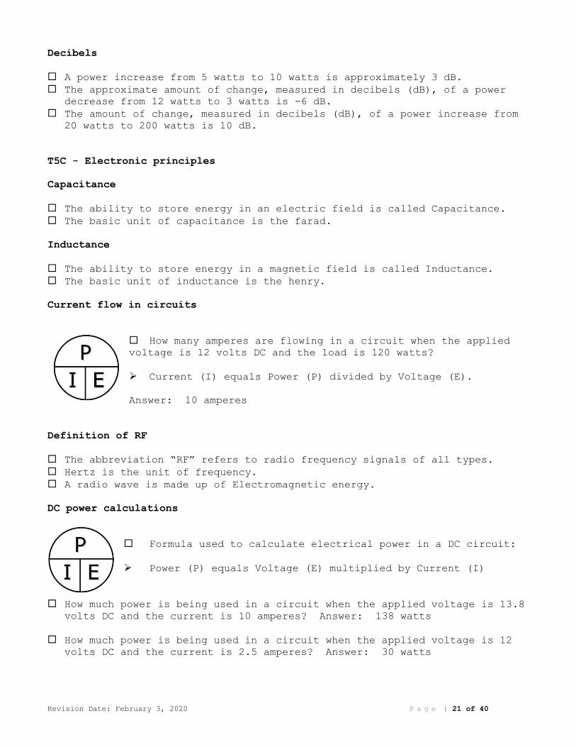
Current flow in circuits
How many amperes are flowing in a circuit when the applied
voltage is 12 volts DC and the load is 120 watts?
➢ Current (I) equals Power (P) divided by Voltage (E).
Answer: 10 amperes
Definition of RF
The abbreviation “RF” refers to radio frequency signals of all types.
Hertz is the unit of frequency.
A radio wave is made up of Electromagnetic energy.
DC power calculations
Formula used to calculate electrical power in a DC circuit:
➢ Power (P) equals Voltage (E) multiplied by Current (I)
How much power is being used in a circuit when the applied voltage is 13.8 volts DC and the current is 10 amperes? Answer: 138 watts
How much power is being used in a circuit when the applied voltage is 12 volts DC and the current is 2.5 amperes? Answer: 30 watts
Revision Date: February 3, 2020 P a g e | 22 of 40
Impedance
Impedance is a measure of the opposition to AC current flow in a circuit.
Ohms is the unit of impedance.
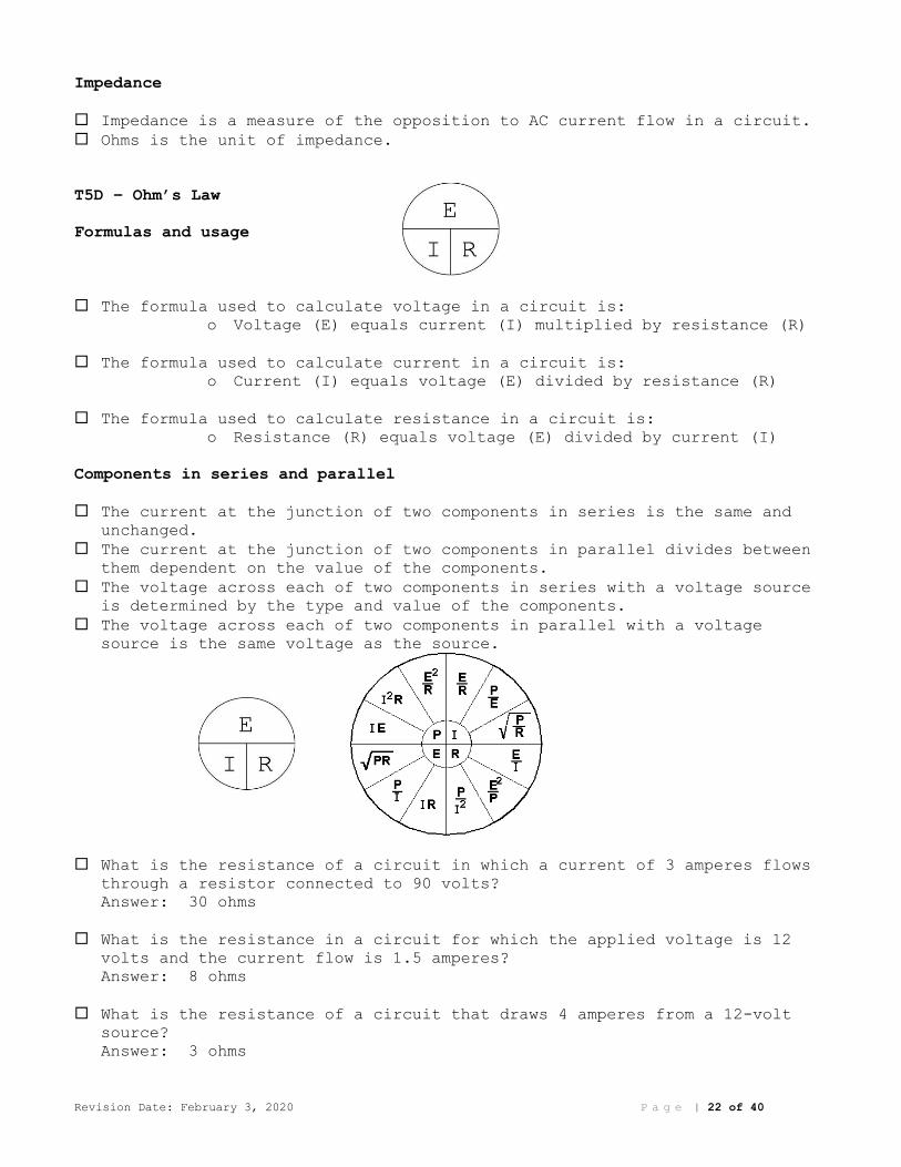
T5D – Ohm’s Law
Formulas and usage
The formula used to calculate voltage in a circuit is: o Voltage (E) equals current (I) multiplied by resistance (R)
The formula used to calculate current in a circuit is: o Current (I) equals voltage (E) divided by resistance (R)
The formula used to calculate resistance in a circuit is: o Resistance (R) equals voltage (E) divided by current (I)
Components in series and parallel
The current at the junction of two components in series is the same and unchanged.
The current at the junction of two components in parallel divides between them dependent on the value of the components.
The voltage across each of two components in series with a voltage source is determined by the type and value of the components.
The voltage across each of two components in parallel with a voltage source is the same voltage as the source.
What is the resistance of a circuit in which a current of 3 amperes flows through a resistor connected to 90 volts?
Answer: 30 ohms
What is the resistance in a circuit for which the applied voltage is 12 volts and the current flow is 1.5 amperes?
Answer: 8 ohms
What is the resistance of a circuit that draws 4 amperes from a 12-volt source?
Answer: 3 ohms
Revision Date: February 3, 2020 P a g e | 23 of 40
What is the current in a circuit with an applied voltage of 120 volts and a resistance of 80 ohms?
Answer: 1.5 amperes
What is the current through a 100-ohm resistor connected across 200 volts? Answer: 2 amperes
What is the current through a 24-ohm resistor connected across 240 volts? Answer: 10 amperes
What is the voltage across a 2-ohm resistor if a current of 0.5 amperes flows through it?
Answer: 1 volt
What is the voltage across a 10-ohm resistor if a current of 1 ampere flows through it?
Answer: 10 volts
What is the voltage across a 10-ohm resistor if a current of 2 amperes flows through it?
Answer: 20 volts
Revision Date: February 3, 2020 P a g e | 24 of 40
SUBELEMENT T6 – Electrical components; circuit diagrams; component functions
– [4 Exam Questions - 4 Groups]
T6A - Electrical components
Fixed and variable resistors
A resistor opposes the flow of current in a DC circuit.
A Potentiometer is often used as an adjustable volume control.
Resistance is controlled by a potentiometer.
Capacitors
A capacitor stores energy in an electric field.
A Capacitor consists of two or more conductive surfaces separated by an insulator.
Inductors
An Inductor stores energy in a magnetic field.
An Inductor is usually constructed as a coil of wire.
Fuses
A Fuse is used to protect other circuit components from current overloads.
Switches
A Switch is used to connect or disconnect electrical circuits.
Batteries
The following battery types are rechargeable:
Nickel-metal hydride
Lithium-ion
Lead-acid gel-cell (All of these choices are correct)
Carbon-zinc battery types are not rechargeable.
T6B – Semiconductors
Basic principles and applications of solid-state devices
Transistor
A Transistor uses a voltage or current signal to control current flow.
A Transistor can be used as an electronic switch or amplifier.
A Transistor can consist of three layers of semiconductor material.
Revision Date: February 3, 2020 P a g e | 25 of 40
A Transistor can amplify signals.
A Transistor could be the primary gain-producing component in an RF power amplifier.
Gain is the term that describes a device's ability to amplify a signal.
Field Effect Transistor (FET)
Diode
A Diode allows current to flow in only one direction.
The cathode lead of a semiconductor diode often marked with a stripe on the package.
Light Emitting Diode (LED)
The names of the two electrodes of a diode are the anode and cathode.
T6C - Circuit diagrams; schematic symbols
Schematic is the name of an electrical wiring diagram that uses standard component symbols.
The symbols on an electrical schematic represent electrical components.
The way components are interconnected is accurately represented in electrical schematics.
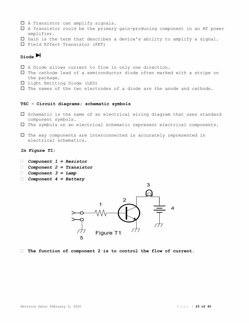
In Figure T1:
Component 1 = Resistor
Component 2 = Transistor
Component 3 = Lamp
Component 4 = Battery
The function of component 2 is to control the flow of current.
Revision Date: February 3, 2020 P a g e | 26 of 40
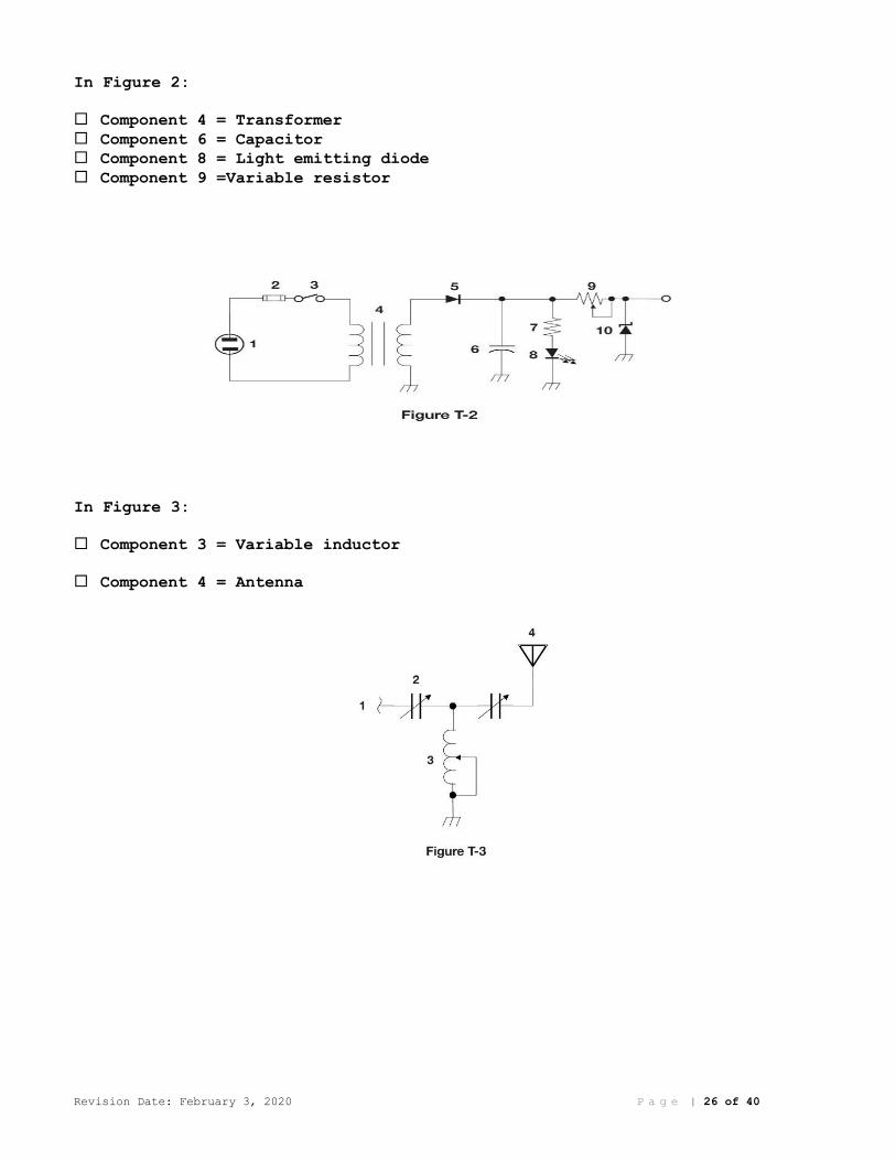
In Figure 2:
Component 4 = Transformer
Component 6 = Capacitor
Component 8 = Light emitting diode
Component 9 =Variable resistor
In Figure 3:
Component 3 = Variable inductor
Component 4 = Antenna

Revision Date: February 3, 2020 P a g e | 27 of 40
T6D - Component functions
Rectification
Rectifier devices or circuits change an alternating current into a varying direct current signal.
Switches
A relay is an electrically-controlled switch.
A Single-pole single-throw switch is represented by component 3 in figure T2.
Indicators
A Meter displays an electrical quantity as a numeric value.
A Light Emitting Diode (LED) is commonly used as a visual indicator.
Power supply components
A Regulator circuit controls the amount of voltage from a power supply.
Resonant circuit
An inductor and a capacitor connected in series or parallel to form a filter is a resonant or tuned circuit.
Shielding
A common reason to use shielded wire is to prevent coupling of unwanted signals to or from the wire.
Power transformers
A Transformer is commonly used to change 120V AC house current to a lower AC voltage for other uses.
Integrated circuits
An integrated circuit is a device that combines several semiconductors and other components into one package.
Revision Date: February 3, 2020 P a g e | 28 of 40
SUBELEMENT T7 – Station equipment: common transmitter and receiver problems;
antenna measurements; troubleshooting; basic repair and testing – [4 Exam
Questions - 4 Groups]
T7A – Station equipment
Receivers
Sensitivity is the term which describes the ability of a receiver to detect the presence of a signal.
Selectivity is the term which describes the ability of a receiver to discriminate between multiple signals.
Transmitters
An Oscillator circuit generates a signal at a specific frequency.
A Mixer is used to convert a radio signal from one frequency to another.
Transceivers
A transceiver is a unit combining the functions of a transmitter and a receiver.
The push-to-talk (PTT) function is what switches between receive and transmit.
Modulation
Modulation describes combining speech with an RF carrier signal.
Transverters
A Transverter device converts the RF input and output of a transceiver to another band.
Transmit and receive amplifiers
The function of the SSB/CW-FM switch on a VHF power amplifier is to set the amplifier for proper operation in the selected mode.
An RF power amplifier device increases the low-power output from a handheld transceiver.
An RF preamplifier is installed between the antenna and receiver.
T7B – Common transmitter and receiver problems
Interference and consumer electronics
You can reduce or eliminate interference from an amateur transmitter to a nearby telephone by putting an RF filter on the telephone.
Part 15 devices
A Part 15 device is an unlicensed device that may emit low-powered radio signals on frequencies used by a licensed service.
Revision Date: February 3, 2020 P a g e | 29 of 40
Off frequency signals and Distortion
If you receive a report that your audio signal through the repeater is distorted or unintelligible:
o Your transmitter is slightly off frequency
o Your batteries are running low
o You are in a bad location
(All of these choices are correct)
Symptoms of overload and overdrive
A broadcast AM or FM radio could receive an amateur radio transmission unintentionally if the receiver is unable to reject strong signals outside
the AM or FM band.
Over-modulation
If you are told your FM handheld or mobile transceiver is over-deviating, talk farther away from the microphone.
RF feedback
A symptom of RF feedback in a transmitter or transceiver is reports of garbled, distorted, or unintelligible voice transmissions.
Causes of interference
The first step to resolve cable TV interference from your ham radio transmission is be sure all TV coaxial connectors are installed properly.
All of the following can cause radio frequency interference: o Fundamental overload
o Harmonics
o Spurious emissions
(All of these choices are correct)
Overload of a non-amateur radio or TV receiver by an amateur signal be reduced or eliminated by blocking the amateur signal with a filter at the
antenna input of the affected receiver.
If a neighbor tells you that your station’s transmissions are interfering with their radio or TV reception make sure that your station is
functioning properly and that it does not cause interference to your own
radio or television when it is tuned to the same channel.
A Band-reject filter can reduce overload to a VHF transceiver from a nearby FM broadcast station.
If something in a neighbor’s home is causing harmful interference to your amateur station:
o Work with your neighbor to identify the offending device
o Politely inform your neighbor about the rules that prohibit the use of
devices that cause interference
o Check your station and make sure it meets the standards of good amateur
practice
(All of these choices are correct)

Revision Date: February 3, 2020 P a g e | 30 of 40
T7C – Antenna measurements and troubleshooting
Standing Wave Ratio (SWR)
A standing wave ratio (SWR) is a measure of how well a load is matched to a transmission line.
A reading of 1 to 1 (1:1) on an SWR meter indicates a perfect impedance match between the antenna and the feed line.
An SWR reading of 4:1 indicates an impedance mismatch.
Most solid-state amateur radio transmitters reduce output power as SWR increases to protect the output amplifier transistors.
Power lost in a feed line is converted into heat.
Measuring SWR
A Directional wattmeter could be used to determine if a feed line and antenna are properly matched.
An antenna analyzer can be used to determine if an antenna is resonant at the desired operating frequency.
Dummy loads
A dummy load consists of a non-inductive resistor and a heat sink.
The primary purpose of a dummy load is to prevent transmitting signals over the air when making tests.
Coaxial cables and Causes of feed line failures
A disadvantage of air core coaxial cable when compared to foam or solid dielectric types is it requires special techniques to prevent water
absorption.
Moisture contamination is the most common cause for failure of coaxial cables.
The outer jacket of coaxial cable needs to be resistant to ultraviolet light because ultraviolet light can damage the jacket and allow water to
enter the cable.
T7D – Basic repair and testing
Soldering
Rosin-core solder is best for radio and electronic use.
A characteristic appearance of a cold solder joint is a grainy or dull surface. (not desired)
Using and Connecting a voltmeter
A voltmeter is used to measure electric potential or electromotive force.
The correct way to connect a voltmeter to a circuit is in parallel with the circuit.
Revision Date: February 3, 2020 P a g e | 31 of 40
Using and Connecting an ammeter
A simple ammeter is connected in series with the circuit.
An ammeter is used to measure electric current.
Using and Connecting an ohmmeter
An ohmmeter is used to measure resistance.
Precautions
Attempting to measure voltage when using the resistance setting might damage a multimeter.
Precautions should be taken when measuring circuit resistance with an ohmmeter --ensure that the circuit is not powered
Precautions should be taken when measuring high voltages with a voltmeter – ensure that the voltmeter and leads are rated for use at the voltages to
be measured.
Use of Measuring Equipment
Voltage and resistance are commonly made using a multimeter.
When an ohmmeter, connected across an unpowered circuit, initially indicates a low resistance and then shows increasing resistance with time,
usually, the circuit contains a large capacitor.
Revision Date: February 3, 2020 P a g e | 32 of 40
SUBELEMENT T8 – Modulation modes: amateur satellite operation; operating
activities; non-voice and digital communications – [4 Exam Questions - 4
Groups]
T8A – Modulation modes
Choice of emission type
Single sideband is a form of amplitude modulation.
Single sideband (SSB) voice mode is most often used for long-distance (weak signal) contacts on the VHF and UHF bands.
Upper sideband is normally used for 10-meter HF, VHF, and UHF single-sideband communications.
Frequency Modulation (FM) is most commonly used for VHF and UHF voice repeaters.
Frequency Modulation (FM) is most commonly used for VHF packet radio transmissions.
An advantage of single sideband (SSB) over FM for voice transmissions is SSB signals have narrower bandwidth.
CW emission has the narrowest bandwidth.
Bandwidth of various signals
The approximate bandwidth of a single sideband (SSB) voice signal is 3 kHz.
The approximate bandwidth of a VHF repeater FM phone signal is between 10 and 15 kHz.
The typical bandwidth of analog fast-scan TV transmissions on the 70-centimeter band is about 6 MHz.
The approximate maximum bandwidth required to transmit a CW signal is 150 Hz.
T8B - Amateur satellite operation
Doppler shift and spin fading
With regard to satellite communications, Doppler shift is an observed change in signal frequency caused by relative motion between the satellite
and the earth station.
Rotation of the satellite and its antennas causes spin fading of satellite signals.
Basic orbits
An amateur satellite may be in a Low Earth Orbit (LEO).
Revision Date: February 3, 2020 P a g e | 33 of 40
Operating protocols
All of these modes of transmission are commonly used by amateur radio satellites:
o SSB
o FM
o CW/data
(All of these choices are correct)
When a satellite is operating in mode U/V, the satellite uplink is in the 70-centimeter band and the downlink is in the 2-meter band.
A good way to judge whether your uplink power is neither too low nor too high is your signal strength on the downlink should be about the same as
the beacon.
Transmitter power considerations
Blocking access by other users is the impact of using too much effective radiated power on a satellite uplink.
Telemetry and telecommand
A satellite beacon is a transmission from a satellite that contains status information.
Health and status of the satellite telemetry information is typically transmitted by satellite beacons.
Anyone who can receive the telemetry signal from a space station.
Satellite tracking
Satellite tracking programs provide: o Maps showing the real-time position of the satellite track over the
earth
o The time, azimuth, and elevation of the start, maximum altitude, and
end of a pass
o The apparent frequency of the satellite transmission, including effects
of Doppler shift
(All of these choices are correct)
The Keplerian elements are inputs to a satellite tracking program.
T8C – Operating activities
Contests
Contesting as an operating activity involves contacting as many stations as possible during a specified period.
A good procedure when contacting another station in a radio contest is send only the minimum information needed for proper identification and the
contest exchange.
Linking over the internet
A gateway is an amateur radio station that is used to connect other amateur stations to the internet.
Revision Date: February 3, 2020 P a g e | 34 of 40
Access to some Internet Radio Linking Project (IRLP) nodes is accomplished by using DTMF signals.
The Internet Radio Linking Project (IRLP) is a technique to connect amateur radio systems, such as repeaters, via the internet using Voice
Over Internet Protocol (VoIP).
Voice Over Internet Protocol (VoIP), as used in amateur radio, is a method of delivering voice communications over the internet using digital
techniques.
You might obtain a list of active nodes that use VoIP: o By subscribing to an on line service
o From on line repeater lists maintained by the local repeater frequency
coordinator
o From a repeater directory
(All of these choices are correct)
You must register your call sign and provide proof of license before you may use the EchoLink system to communicate using a repeater.
Radio direction finding
Radio direction finding methods are used to locate sources of noise interference or jamming.
A directional antenna would be useful for a hidden transmitter hunt.
Grid locators
A grid locator is a letter-number designator assigned to a geographic location.
T8D – Non-voice and digital communications
Digital modes
The following are digital communications modes: o Packet radio
o IEEE 802.11
o JT65
(All of these choices are correct)
The following operating activities are supported by digital mode software in the WSJT suite:
o Moonbounce or Earth-Moon-Earth
o Weak-signal propagation beacons
o Meteor scatter
(All of these choices are correct)
FT8 is a digital mode capable of operating in low signal-to-noise conditions that transmits on 15-second intervals.
CW
International Morse code is used when sending CW in the amateur bands.
An electronic keyer is a device that assists in manual sending of Morse code.

Revision Date: February 3, 2020 P a g e | 35 of 40
Packet radio
Packet transmissions may include: o A check sum that permits error detection
o A header that contains the call sign of the station to which the
information is being sent
o Automatic repeat request in case of error
(All of these choices are correct)
PSK31
Phase Shift Keying (PSK)
APRS
Automatic Packet Reporting System (APRS)
An application of APRS (Automatic Packet Reporting System) is providing real-time tactical digital communications in conjunction with a map
showing the locations of stations.
Error detection and correction
An ARQ transmission system is a digital scheme whereby the receiving station detects errors and sends a request to the sending station to
retransmit the information.
Image Signals and NTSC
An analog fast scan color TV signal is a type of transmission indicated by the term "NTSC”.
Amateur radio networking
Broadband-Hamnet(TM), also referred to as a high-speed multi-media network, is best described as an amateur-radio-based data network using
commercial Wi-Fi gear with modified firmware.
Digital Mobile Radio
DMR (Digital Mobile Radio) is a technique for time-multiplexing two digital voice signals on a single 12.5 kHz repeater channel.
Global Positioning System (GPS)
A Global Positioning System (GPS) receiver is used to provide data to the transmitter when sending automatic position reports from a mobile amateur
radio station.
Revision Date: February 3, 2020 P a g e | 36 of 40
SUBELEMENT T9 – Antennas and feed lines - [2 Exam Questions - 2 Groups]
T9A – Antennas
Concept of dipole antennas
A half-wave dipole antenna radiates the strongest signal broadside to the antenna.
Vertical and horizontal polarization
A simple dipole oriented parallel to the Earth's surface is a horizontally polarized antenna.
Concept of gain
The gain of an antenna is the increase in signal strength in a specified direction compared to a reference antenna.
A beam antenna is an antenna that concentrates signals in one direction.
The quad, Yagi, and dish are directional antennas.
Common portable and mobile antennas
A disadvantage of the “rubber duck” antenna supplied with most handheld radio transceivers when compared to a full-sized quarter-wave antenna is
it does not transmit or receive as effectively.
A disadvantage of using a handheld VHF transceiver, with its integral antenna, inside a vehicle is signals might not propagate well due to the
shielding effect of the vehicle.
An advantage of using a properly mounted 5/8 wavelength antenna for VHF or UHF mobile service is it has a lower radiation angle and more gain than a
1/4 wavelength antenna.
Relationships between resonant length and frequency
You would shorten a dipole antenna to make it resonant on a higher frequency.
Inserting an inductor in the radiating portion of the antenna to make it electrically longer is a type of antenna loading.
The approximate length, in inches, of a quarter-wavelength vertical antenna for 146 MHz is 19 inches.
The approximate length, in inches, of a half-wavelength 6-meter dipole antenna is 112 inches.
T9B – Feed lines
Types
Coaxial cable is the most common feed line selected for amateur radio antenna systems because it is easy to use and requires few special
installation considerations.
The impedance of most coaxial cables used in amateur radio installations is 50 ohms.
Revision Date: February 3, 2020 P a g e | 37 of 40
Attenuation vs frequency
In general, the loss increases as the frequency of a signal passing through coaxial cable is increased.
The electrical difference between RG-58 and RG-8 coaxial cable is RG-8 cable has less loss at a given frequency.
Air-insulated hard line has the lowest loss at VHF and UHF.
SWR concepts
It is important to have low SWR when using coaxial cable feed line to reduce signal loss.
Antenna tuners
The major function of an antenna tuner (antenna coupler) is it matches the antenna system impedance to the transceiver's output impedance.
RF Connectors: selecting, weather protection
A Type N connector is most suitable for frequencies above 400 MHz.
PL-259 type coax connectors are commonly used at HF frequencies.
Coax connectors exposed to the weather should be sealed against water intrusion to prevent an increase in feed line loss.
A loose connection in an antenna or a feed line can cause erratic changes in SWR readings.
Revision Date: February 3, 2020 P a g e | 38 of 40
SUBELEMENT T0 – Electrical safety: AC and DC power circuits; antenna
installation; RF hazards – [3 Exam Questions - 3 Groups]
T0A – Power circuits and hazards
Hazardous voltages
Electrical current flowing through the body is a hazard because: o It may cause injury by heating tissue
o It may disrupt the electrical functions of cells
o It may cause involuntary muscle contractions
(All of these choices are correct)
A hazard might still exist in a power supply when it is turned off and disconnected -- You might receive an electric shock from the charge stored
in large capacitors.
Fuses and circuit breakers
The purpose of a fuse in an electrical circuit is to interrupt power in case of overload.
It is unwise to install a 20-ampere fuse in the place of a 5-ampere fuse because excessive current could cause a fire.
A fuse or circuit breaker in series with the AC hot conductor should always be included in home-built equipment that is powered from 120V AC
power circuits.
Grounding
In the United States, equipment ground is connected to the green wire in a three-wire electrical AC plug.
All external ground rods or earth connections should be bonded together with heavy wire or conductive strap.
Lightning protection
This precaution should be taken when installing devices for lightning protection in a coaxial cable feed line -- Mount all of the protectors on
a metal plate that is in turn connected to an external ground rod.
Battery safety
A safety hazard of a 12-volt storage battery is shorting the terminals can cause burns, fire, or an explosion.
If a lead-acid storage battery is charged or discharged too quickly, the battery could overheat, give off flammable gas, or explode.
Electrical code compliance
Good ways to guard against electrical shock at your station: o Use three-wire cords and plugs for all AC powered equipment
o Connect all AC powered station equipment to a common safety ground
o Use a circuit protected by a ground-fault interrupter
(All of these choices are correct)

Revision Date: February 3, 2020 P a g e | 39 of 40
T0B – Antenna safety
Tower safety
Members of a tower work team should wear a hard hat and safety glasses at all times when any work is being done on the tower.
A good precaution to observe before climbing an antenna tower is put on a carefully inspected climbing harness (fall arrester) and safety glasses.
It is never safe to climb a tower without a helper or observer.
Look for and stay clear of any overhead electrical wires -- It is an important safety precaution to observe when putting up an antenna tower.
An important safety rule to remember when using a crank-up tower is this type of tower must not be climbed unless retracted or mechanical safety
locking devices have been installed.
Tower grounding
Local electrical codes establish grounding requirements for an amateur radio tower or antenna.
A proper grounding method for a tower is separate eight-foot long ground rods for each tower leg, bonded to the tower and each other.
When installing grounding conductors used for lightning protection sharp bends must be avoided.
As a good practice, ensure that connections are short and direct when installing ground wires on a tower for lightning protection.
Erecting an antenna support
The purpose of a safety wire through a turnbuckle used to tension guy lines is to prevent loosening of the guy line from vibration.
Safely installing an antenna
The purpose of a gin pole is to lift tower sections or antennas.
The minimum safe distance from a power line to allow when installing an antenna is enough so that if the antenna falls unexpectedly, no part of it
can come closer than 10 feet to the power wires.
You should avoid attaching an antenna to a utility pole because the antenna could contact high-voltage power lines.
T0C - RF hazards
Radiation exposure
Exposure limits vary with frequency because the human body absorbs more RF energy at some frequencies than at others.
Acceptable methods to determine that your station complies with FCC RF exposure regulations include:
o By calculation based on FCC OET Bulletin 65
o By calculation based on computer modeling
o By measurement of field strength using calibrated equipment
(All of these choices are correct)

Revision Date: February 3, 2020 P a g e | 40 of 40
50 MHz has the lowest value for Maximum Permissible Exposure limit.
Proximity to antennas
If a person accidentally touched your antenna while you were transmitting, they might receive a painful RF burn.
Amateur operators might relocate antennas to prevent exposure to RF radiation in excess of FCC-supplied limits.
RF Exposure to others
Factors affecting the RF exposure of people near an amateur station antenna are:
o Frequency and power level of the RF field
o Distance from the antenna to a person
o Radiation pattern of the antenna
(All of these choices are correct)
Radiation types
VHF and UHF radio signals are Non-ionizing radiation.
RF radiation does not have sufficient energy to cause genetic damage. That’s how it differs from ionizing radiation (radioactivity).
Duty cycle
Duty cycle is one of the factors used to determine safe RF radiation exposure levels because it affects the average exposure of people to
radiation.
The definition of duty cycle during the averaging time for RF exposure is the percentage of time that a transmitter is transmitting.
If the averaging time for exposure is 6 minutes, how much power density is permitted if the signal is present for 3 minutes and absent for 3 minutes
rather than being present for the entire 6 minutes?
Answer: Two (2) times as much
Recognized safe power levels
A maximum power level an amateur radio station may use at VHF frequencies before an RF exposure evaluation is required -- 50 watts PEP at the
antenna.
You can make sure your station stays in compliance with RF safety regulations by re-evaluating the station whenever an item of equipment is
changed.
End of Study Guide