Embed Size (px)
Citation preview
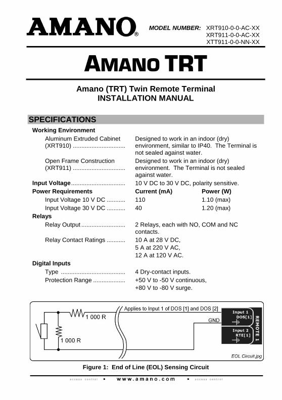
MODEL NUMBER: XRT910-0-0-AC-XX
XRT911-0-0-AC-XX XTT911-0-0-NN-XX
AMANO TRT Amano (TRT) Twin Remote Terminal
INSTALLATION MANUAL
SPECIFICATIONS
Working Environment
Aluminum Extruded Cabinet (XRT910) ...............................
Designed to work in an indoor (dry) environment, similar to IP40. The Terminal is not sealed against water.
Open Frame Construction (XRT911) ...............................
Designed to work in an indoor (dry) environment. The Terminal is not sealed against water.
Input Voltage ................................ 10 V DC to 30 V DC, polarity sensitive.
Power Requirements Current (mA) Power (W)
Input Voltage 10 V DC ........... 110 1.10 (max)
Input Voltage 30 V DC ........... 40 1.20 (max)
Relays
Relay Output .......................... 2 Relays, each with NO, COM and NC contacts.
Relay Contact Ratings ........... 10 A at 28 V DC,
5 A at 220 V AC,
12 A at 120 V AC.
Digital Inputs
Type ...................................... 4 Dry-contact inputs.
Protection Range ................... +50 V to -50 V continuous,
+80 V to -80 V surge.
Figure 1: End of Line (EOL) Sensing Circuit
XRT300-0-0-AC-07 May 2010 Page 2
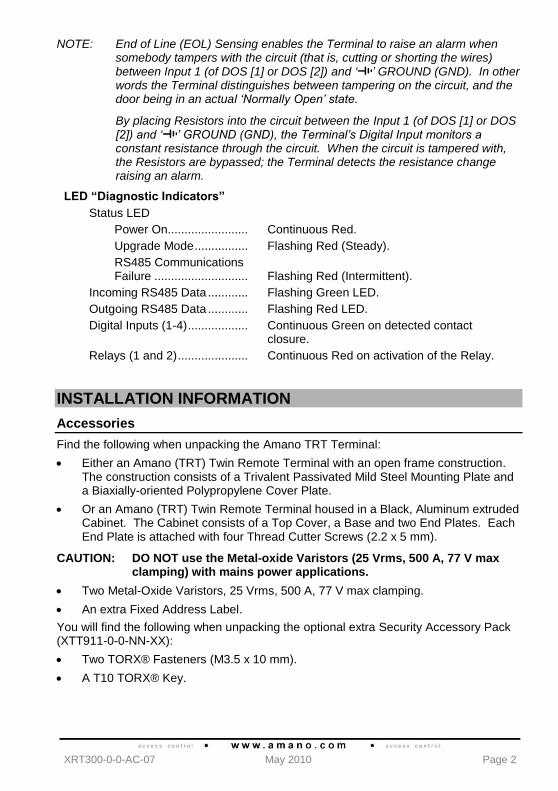
NOTE: End of Line (EOL) Sensing enables the Terminal to raise an alarm when somebody tampers with the circuit (that is, cutting or shorting the wires) between Input 1 (of DOS [1] or DOS [2]) and ‘ ’ GROUND (GND). In other words the Terminal distinguishes between tampering on the circuit, and the door being in an actual ‘Normally Open’ state.
By placing Resistors into the circuit between the Input 1 (of DOS [1] or DOS [2]) and ‘ ’ GROUND (GND), the Terminal’s Digital Input monitors a constant resistance through the circuit. When the circuit is tampered with, the Resistors are bypassed; the Terminal detects the resistance change raising an alarm.
LED “Diagnostic Indicators”
Status LED
Power On........................ Continuous Red.
Upgrade Mode ................ Flashing Red (Steady).
RS485 Communications Failure ............................ Flashing Red (Intermittent).
Incoming RS485 Data ............ Flashing Green LED.
Outgoing RS485 Data ............ Flashing Red LED.
Digital Inputs (1-4) .................. Continuous Green on detected contact closure.
Relays (1 and 2) ..................... Continuous Red on activation of the Relay.
INSTALLATION INFORMATION
Accessories
Find the following when unpacking the Amano TRT Terminal:
Either an Amano (TRT) Twin Remote Terminal with an open frame construction. The construction consists of a Trivalent Passivated Mild Steel Mounting Plate and a Biaxially-oriented Polypropylene Cover Plate.
Or an Amano (TRT) Twin Remote Terminal housed in a Black, Aluminum extruded Cabinet. The Cabinet consists of a Top Cover, a Base and two End Plates. Each End Plate is attached with four Thread Cutter Screws (2.2 x 5 mm).
CAUTION: DO NOT use the Metal-oxide Varistors (25 Vrms, 500 A, 77 V max clamping) with mains power applications.
Two Metal-Oxide Varistors, 25 Vrms, 500 A, 77 V max clamping.
An extra Fixed Address Label.
You will find the following when unpacking the optional extra Security Accessory Pack (XTT911-0-0-NN-XX):
Two TORX® Fasteners (M3.5 x 10 mm).
A T10 TORX® Key.
XRT300-0-0-AC-07 May 2010 Page 3
General
Remember the following when installing the Amano TRT Terminal:
Communications Distance
The RS485 communications distance between the Amano Controller and the LAST Amano TRT in a cable run, MUST NOT exceed 1 km (1 090 yd). Achieve this by using good quality screened, twisted 2-pair cable, with the screen EARTHED at one end.
Jumper Links
Long transmission lines or multiple “star” connections, may cause communication problems. Placing a Jumper Link across the jumper [TR1] in the LAST UNIT AT THE END OF THE CABLE RUN should solve the problem. See Figure 5 for the location of the jumper [TR1].
Distance between the Amano TRT and its Multi-mode Remote Readers
The maximum cable distance between the Amano TRT and its Multi-mode Remote Readers MUST NOT exceed 10 m (33 ft). Achieve this by using good quality screened, twisted pair cable.
Distance between the Amano TRT and its Wiegand Readers
CAUTION: When implementing the 150 m (164 yd) cable distances with Amano Wiegand Readers use the 12 V power output option.
For maximum data communications distance, install the Wiegand Readers no further than 150 m (164 yd) from the Terminal. The cable individual conductor cross-sectional area should not be less than 0.2 mm
2 (0.0003 in
2).
Avoid mutual interference, install Wiegand Readers no closer than 500 mm (20 in) apart.
Distance between Amano Units
You can mount Amano TRT‟s directly next to each other.
To avoid mutual interference, install the Amano Remotes alongside each other at least 500 mm (20 in) apart.
EARTH Connection
Connect the Amano TRT Terminal to a good EARTH point. Using the RS485 Port, connect the EARTH Lead to the „ ‟ Terminal. Mains EARTH can be used, but electrical noise may exist.
CAUTION: When using the Amano TRT with FCC approved accessories, ensure that the RS485 cable is routed through a separate grommet to the power cable. Also ensure that you use a CE approved Power Supply Unit.
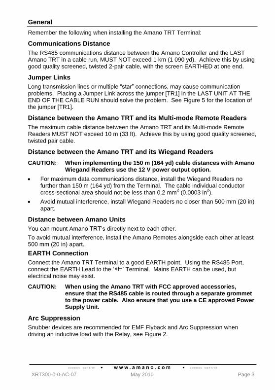
Arc Suppression
Snubber devices are recommended for EMF Flyback and Arc Suppression when driving an inductive load with the Relay, see Figure 2.
XRT300-0-0-AC-07 May 2010 Page 4
Figure 2: EMF Flyback and Arc Suppression
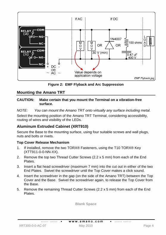
Mounting the Amano TRT
CAUTION: Make certain that you mount the Terminal on a vibration-free surface.
NOTE: You can mount the Amano TRT onto virtually any surface including metal.
Select the mounting position of the Amano TRT Terminal, considering accessibility, routing of wires and visibility of the LEDs.
Aluminum Extruded Cabinet (XRT910)
Secure the Base to the mounting surface, using four suitable screws and wall plugs, nuts and bolts or rivets.
Top Cover Release Mechanism
1. If installed, remove the two TORX® Fasteners, using the T10 TORX® Key (XTT911-0-0-NN-XX).
2. Remove the top two Thread Cutter Screws (2.2 x 5 mm) from each of the End Plates.
3. Insert a flat head screwdriver (maximum 7 mm) into the cut out in either of the two End Plates. Swivel the screwdriver until the Top Cover makes a click sound.
4. Insert the screwdriver in the gap (on the side of the Amano TRT) between the Top Cover and the Base. Swivel the screwdriver again, to release the Top Cover from the Base.
5. Remove the remaining Thread Cutter Screws (2.2 x 5 mm) from each of the End Plates.
Blank Space
XRT300-0-0-AC-07 May 2010 Page 5
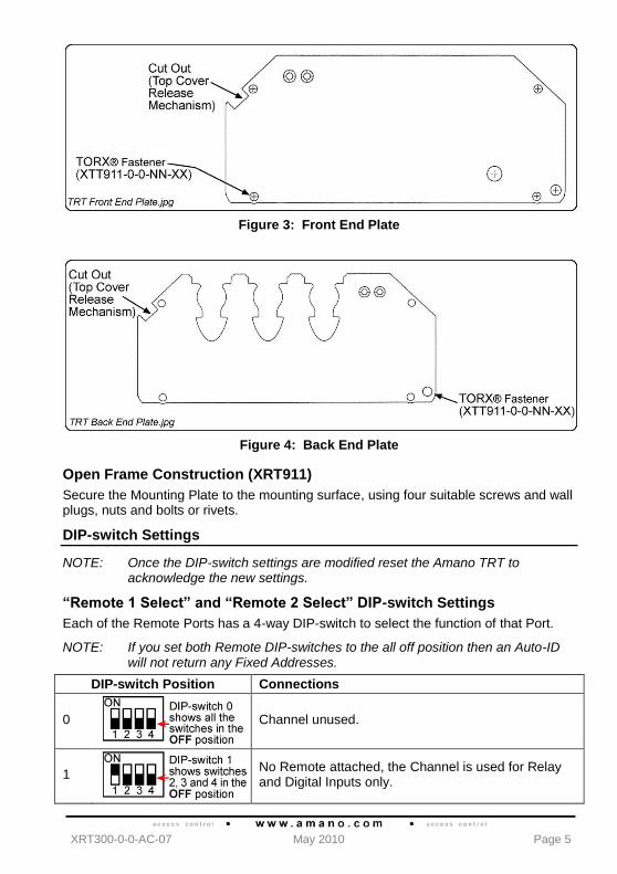
Figure 3: Front End Plate
Figure 4: Back End Plate
Open Frame Construction (XRT911)
Secure the Mounting Plate to the mounting surface, using four suitable screws and wall plugs, nuts and bolts or rivets.
DIP-switch Settings
NOTE: Once the DIP-switch settings are modified reset the Amano TRT to acknowledge the new settings.
“Remote 1 Select” and “Remote 2 Select” DIP-switch Settings
Each of the Remote Ports has a 4-way DIP-switch to select the function of that Port.
NOTE: If you set both Remote DIP-switches to the all off position then an Auto-ID will not return any Fixed Addresses.
DIP-switch Position Connections
0
Channel unused.
1
No Remote attached, the Channel is used for Relay and Digital Inputs only.
XRT300-0-0-AC-07 May 2010 Page 6
DIP-switch Position Connections
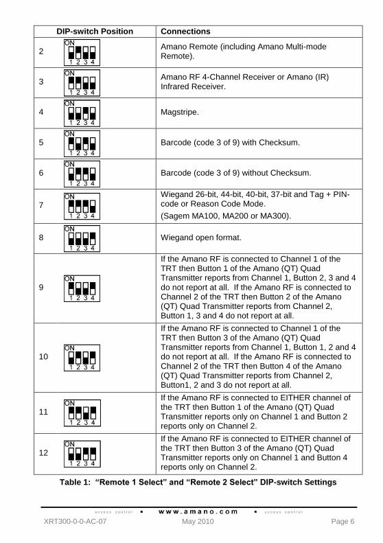
2
Amano Remote (including Amano Multi-mode Remote).
3
Amano RF 4-Channel Receiver or Amano (IR) Infrared Receiver.
4
Magstripe.
5
Barcode (code 3 of 9) with Checksum.
6
Barcode (code 3 of 9) without Checksum.
7
Wiegand 26-bit, 44-bit, 40-bit, 37-bit and Tag + PIN-code or Reason Code Mode.
(Sagem MA100, MA200 or MA300).
8
Wiegand open format.
9
If the Amano RF is connected to Channel 1 of the TRT then Button 1 of the Amano (QT) Quad Transmitter reports from Channel 1, Button 2, 3 and 4 do not report at all. If the Amano RF is connected to Channel 2 of the TRT then Button 2 of the Amano (QT) Quad Transmitter reports from Channel 2, Button 1, 3 and 4 do not report at all.
10
If the Amano RF is connected to Channel 1 of the TRT then Button 3 of the Amano (QT) Quad Transmitter reports from Channel 1, Button 1, 2 and 4 do not report at all. If the Amano RF is connected to Channel 2 of the TRT then Button 4 of the Amano (QT) Quad Transmitter reports from Channel 2, Button1, 2 and 3 do not report at all.
11
If the Amano RF is connected to EITHER channel of the TRT then Button 1 of the Amano (QT) Quad Transmitter reports only on Channel 1 and Button 2 reports only on Channel 2.
12
If the Amano RF is connected to EITHER channel of the TRT then Button 3 of the Amano (QT) Quad Transmitter reports only on Channel 1 and Button 4 reports only on Channel 2.
Table 1: “Remote 1 Select” and “Remote 2 Select” DIP-switch Settings
XRT300-0-0-AC-07 May 2010 Page 7
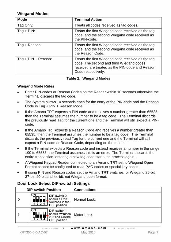
Wiegand Modes
Mode Terminal Action
Tag Only: Treats all codes received as tag codes.
Tag + PIN: Treats the first Wiegand code received as the tag code, and the second Wiegand code received as the PIN-code.
Tag + Reason: Treats the first Wiegand code received as the tag code, and the second Wiegand code received as the Reason Code.
Tag + PIN + Reason: Treats the first Wiegand code received as the tag code. The second and third Wiegand codes received are treated as the PIN-code and Reason Code respectively.
Table 2: Wiegand Modes
Wiegand Mode Rules
Enter PIN-codes or Reason Codes on the Reader within 10 seconds otherwise the Terminal discards the tag code.
The System allows 10 seconds each for the entry of the PIN-code and the Reason Code in Tag + PIN + Reason Mode.
If the Amano TRT expects a PIN-code and receives a number greater than 65535, then the Terminal assumes the number to be a tag code. The Terminal discards the previously read Tag for the current one and the Terminal will still expect a PIN-code.
If the Amano TRT expects a Reason Code and receives a number greater than 65535, then the Terminal assumes the number to be a tag code. The Terminal discards the previously read Tag for the current one and the Terminal will still expect a PIN-code or Reason Code, depending on the mode.
If the Terminal expects a Reason code and instead receives a number in the range 100 to 65535, the Terminal assumes this is an error. The Terminal discards the entire transaction, entering a new tag code starts the process again.
A Wiegand Keypad Reader connected to an Amano TRT set to Wiegand Open Format cannot be configured to read PAC-codes or special key codes.
If using PIN and Reason codes set the Amano TRT switches for Wiegand 26-bit, 37-bit, 40-bit and 44-bit, not Wiegand open format.
Door Lock Select DIP-switch Settings
DIP-switch Position Connections
0
Normal Lock.
1
Motor Lock.
XRT300-0-0-AC-07 May 2010 Page 8
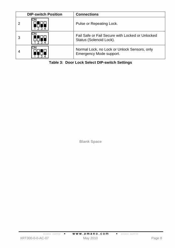
DIP-switch Position Connections
2
Pulse or Repeating Lock.
3
Fail Safe or Fail Secure with Locked or Unlocked Status (Solenoid Lock).
4
Normal Lock, no Lock or Unlock Sensors, only Emergency Mode support.
Table 3: Door Lock Select DIP-switch Settings
Blank Space
XRT300-0-0-AC-07 May 2010 Page 9
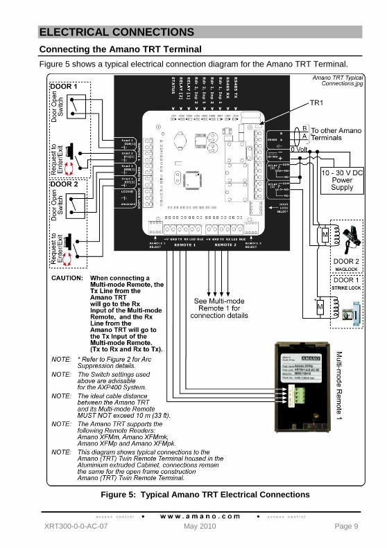
ELECTRICAL CONNECTIONS
Connecting the Amano TRT Terminal
Figure 5 shows a typical electrical connection diagram for the Amano TRT Terminal.
Figure 5: Typical Amano TRT Electrical Connections
XRT300-0-0-AC-07 May 2010 Page 10
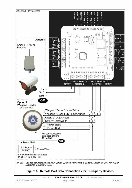
Figure 6: Remote Port Data Connections for Third-party Devices
XRT300-0-0-AC-07 May 2010 Page 11
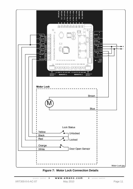
Figure 7: Motor Lock Connection Details
XRT300-0-0-AC-07 May 2010 Page 12
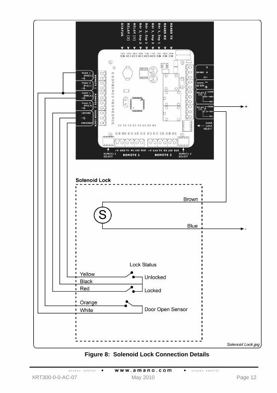
Figure 8: Solenoid Lock Connection Details
XRT300-0-0-AC-07 May 2010 Page 13
Fixed Address Label
Once the Amano TRT is installed, sketch a rough site plan. Attach the loose (additional Fixed Address Label packaged with the Terminal) Fixed Address Label in the position of the Terminal on the sketched site plan. When the system installation is complete and all the units are represented on the site plan by their Fixed Address Labels, file the site plan for future reference.
GUARANTEE OR WARRANTY
CAUTION: We reserve the right to nullify the products guarantee or warranty where you have not properly installed the Metal-oxide Varistors.
This product conforms to our Guarantee or Warranty details placed on our Web Site, to read further please go to www.amano.com.
USER NOTES

XRT300-0-0-AC-07 May 2010 Page 14
USER NOTES

XRT300-0-0-AC-07 May 2010 Page 15
USER NOTES

XRT300-0-0-AC-07 May 2010 Page 16
Security Systems Division
180 Alt. 19, Suite A, Palm Harbor, FL 34683
Technical Support: (800) 390 5837
Corporate Headquarters
140 Harrison Avenue, Roseland, NJ 07068-1239,
(800) 526-2559
www.amano.com
This manual is applicable to the Amano (TRT) Twin Remote Terminal, XRT910-0-0-AC-02, XRT911-0-0-AC-01 and XTT911-0-0-NN-00.
(The last two digits of the Amano stock code indicate the issue status of the product).
XRT300-0-0-AC-07 Issue 08 May 2010 TRT\Amano USA\LATEST ISSUE \
AmanoTRT-insm-en-08.docx