Embed Size (px)
Citation preview
Type series booklet1592.551/6--EN Amamix
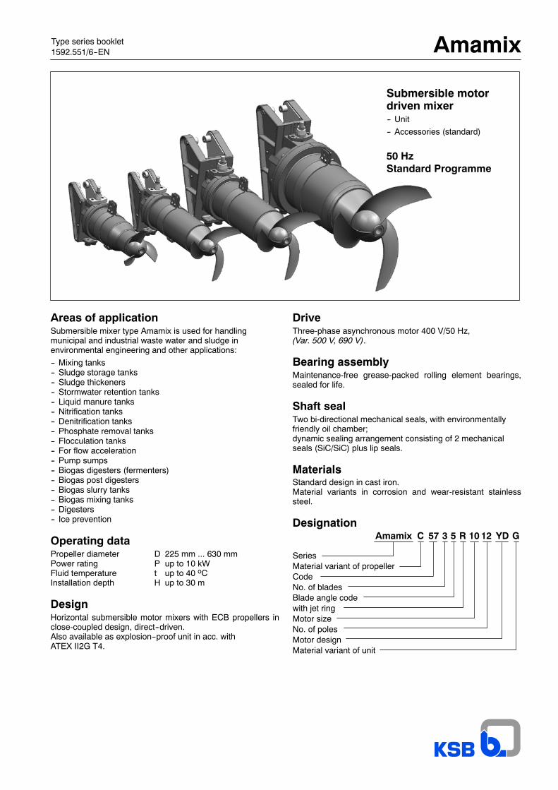
Submersible motordriven mixer-- Unit
-- Accessories (standard)
50 HzStandard Programme
Areas of applicationSubmersible mixer type Amamix is used for handlingmunicipal and industrial waste water and sludge inenvironmental engineering and other applications:
-- Mixing tanks-- Sludge storage tanks-- Sludge thickeners-- Stormwater retention tanks-- Liquid manure tanks-- Nitrification tanks-- Denitrification tanks-- Phosphate removal tanks-- Flocculation tanks-- For flow acceleration-- Pump sumps-- Biogas digesters (fermenters)-- Biogas post digesters-- Biogas slurry tanks-- Biogas mixing tanks-- Digesters-- Ice prevention
Operating dataPropeller diameter D 225 mm ... 630 mmPower rating P up to 10 kWFluid temperature t up to 40 oCInstallation depth H up to 30 m
DesignHorizontal submersible motor mixers with ECB propellers inclose-coupled design, direct--driven.Also available as explosion--proof unit in acc. withATEX II2G T4.
DriveThree-phase asynchronous motor 400 V/50 Hz,(Var. 500 V, 690 V).
Bearing assemblyMaintenance-free grease-packed rolling element bearings,sealed for life.
Shaft sealTwo bi-directional mechanical seals, with environmentallyfriendly oil chamber;dynamic sealing arrangement consisting of 2 mechanicalseals (SiC/SiC) plus lip seals.
MaterialsStandard design in cast iron.Material variants in corrosion and wear-resistant stainlesssteel.
Designation
SeriesMaterial variant of propellerCodeNo. of bladesBlade angle codewith jet ringMotor sizeNo. of polesMotor designMaterial variant of unit
Amamix C YD GR 10 1257 53
Amamix
2
Table of contentsPage
Modular design of Amamix 3
Product advantages, example Amamix 400 G 4
Product advantages, example Amamix 400 C 5
Guarantee, testing and quality control, scope of supply, frequency inverter operation, warranty 6
Material variant, material comparison, oil fill for mech. seal reservoir, materials -- information 7
TECHNICAL DETAILS -- STANDARD PROGRAMME / (standard variants) 8
OPTIONS (extra charge) and information on special designs 9
General drawing with list of components (Example: Amamix C 4135/4 8 UDG) 10
General drawing with list of components (Example: Amamix C 4135/4 8 YDC) 11
Technical data 12--25
Version without jet ring
Amamix 200 - material variant G Page 12Amamix 200 - material variant C Page 13
Amamix 300 - material variant G Page 14Amamix 300 - material variant C Page 15
Amamix 400 - material variant G Page 16Amamix 400 - material variant C Page 17
Amamix 600 - material variant G Page 18Amamix 600 - material variant C Page 19
Version with jet ring
Amamix 300 - material variant G Page 20Amamix 300 - material variant C Page 21
Amamix 400 - material variant G Page 22Amamix 400 - material variant C Page 23
Amamix 600 - material variant G Page 24Amamix 600 - material variant G Page 25
Overview of accessories 27
Standard accessories 6 28--29
Standard accessories 7 30--33
Standard accessories 22 / Accessories 22 -- Options 34--55
Standard accessories 4 56--57
Other accessories 58
Guide rails, minimum submergence and wall/floor clearance 59
Amamix
3
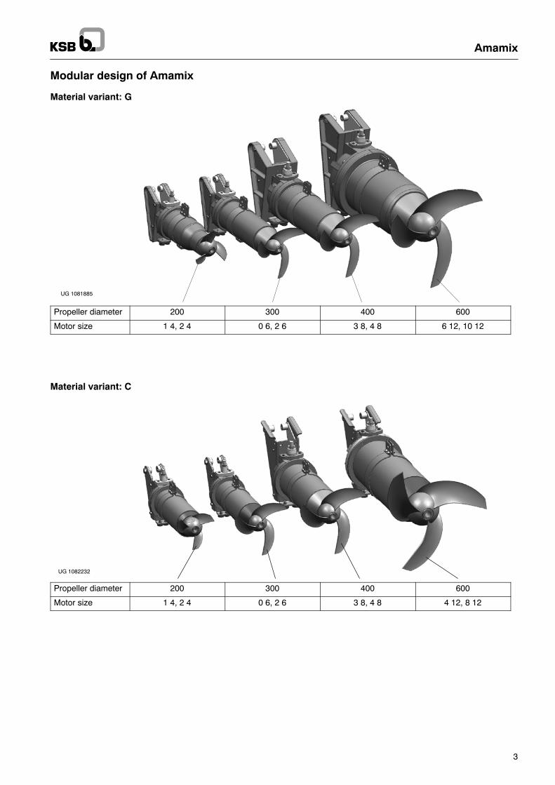
Modular design of Amamix
Material variant: G
UG 1081885
Propeller diameter 200 300 400 600
Motor size 1 4, 2 4 0 6, 2 6 3 8, 4 8 6 12, 10 12
Material variant: C
UG 1082232
Propeller diameter 200 300 400 600
Motor size 1 4, 2 4 0 6, 2 6 3 8, 4 8 4 12, 8 12
Amamix
4
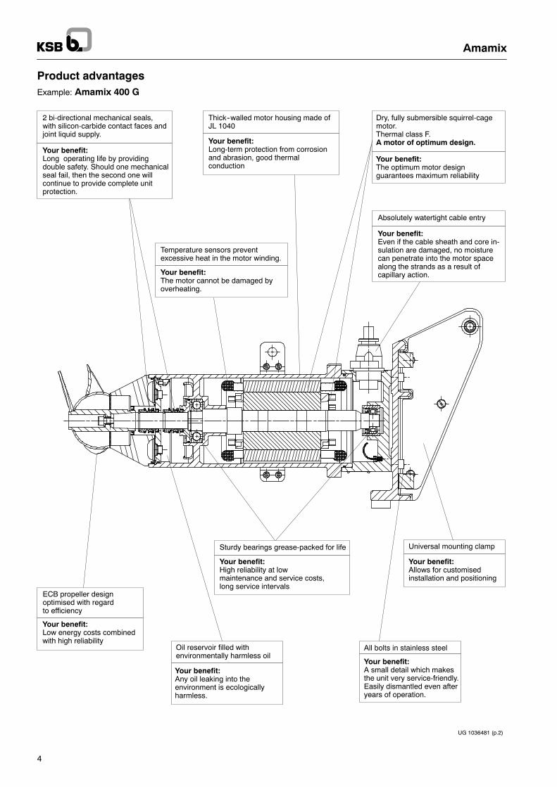
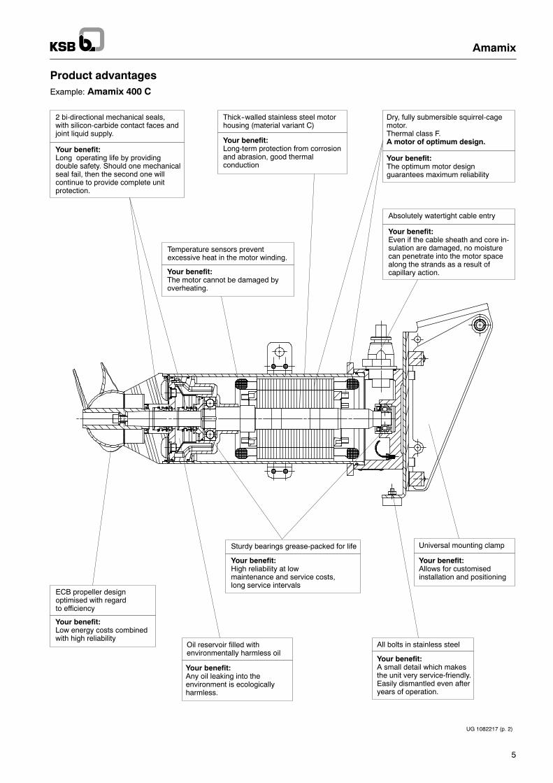
Product advantagesExample: Amamix 400 G
Absolutely watertight cable entry
Your benefit:Even if the cable sheath and core in-sulation are damaged, no moisturecan penetrate into the motor spacealong the strands as a result ofcapillary action.
2 bi-directional mechanical seals,with silicon-carbide contact faces andjoint liquid supply.
Your benefit:Long operating life by providingdouble safety. Should one mechanicalseal fail, then the second one willcontinue to provide complete unitprotection.
Thick--walled motor housing made ofJL 1040
Dry, fully submersible squirrel-cagemotor.Thermal class F.A motor of optimum design.
Your benefit:The optimum motor designguarantees maximum reliability
Your benefit:Long-term protection from corrosionand abrasion, good thermalconduction
Your benefit:The motor cannot be damaged byoverheating.
Temperature sensors preventexcessive heat in the motor winding.
Your benefit:High reliability at lowmaintenance and service costs,long service intervals
Sturdy bearings grease-packed for life
Your benefit:Low energy costs combinedwith high reliability
ECB propeller designoptimised with regardto efficiency
Oil reservoir filled withenvironmentally harmless oil
Your benefit:Any oil leaking into theenvironment is ecologicallyharmless.
All bolts in stainless steel
Your benefit:A small detail which makesthe unit very service-friendly.Easily dismantled even afteryears of operation.
Universal mounting clamp
Your benefit:Allows for customisedinstallation and positioning
UG 1036481 (p.2)
Amamix
5
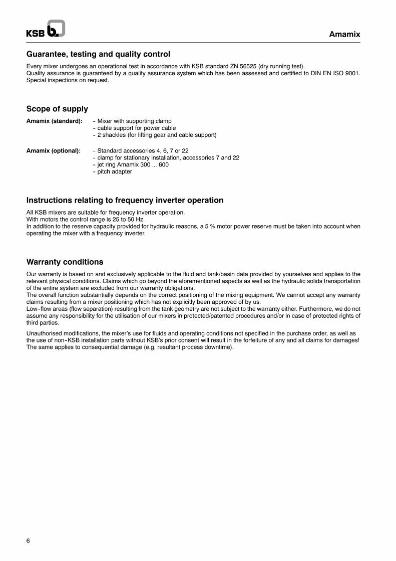
Product advantagesExample: Amamix 400 C
Thick--walled stainless steel motorhousing (material variant C)
Dry, fully submersible squirrel-cagemotor.Thermal class F.A motor of optimum design.
Your benefit:The optimum motor designguarantees maximum reliability
Your benefit:Long-term protection from corrosionand abrasion, good thermalconduction
2 bi-directional mechanical seals,with silicon-carbide contact faces andjoint liquid supply.
Your benefit:Long operating life by providingdouble safety. Should one mechanicalseal fail, then the second one willcontinue to provide complete unitprotection.
Your benefit:The motor cannot be damaged byoverheating.
Temperature sensors preventexcessive heat in the motor winding.
Your benefit:High reliability at lowmaintenance and service costs,long service intervals
Sturdy bearings grease-packed for life
Your benefit:Low energy costs combinedwith high reliability
ECB propeller designoptimised with regardto efficiency
Oil reservoir filled withenvironmentally harmless oil
Your benefit:Any oil leaking into theenvironment is ecologicallyharmless.
All bolts in stainless steel
Your benefit:A small detail which makesthe unit very service-friendly.Easily dismantled even afteryears of operation.
Universal mounting clamp
Your benefit:Allows for customisedinstallation and positioning
UG 1082217 (p. 2)
Absolutely watertight cable entry
Your benefit:Even if the cable sheath and core in-sulation are damaged, no moisturecan penetrate into the motor spacealong the strands as a result ofcapillary action.
Amamix
6
Guarantee, testing and quality controlEvery mixer undergoes an operational test in accordance with KSB standard ZN 56525 (dry running test).Quality assurance is guaranteed by a quality assurance system which has been assessed and certified to DIN EN ISO 9001.Special inspections on request.
Scope of supplyAmamix (standard): -- Mixer with supporting clamp
-- cable support for power cable-- 2 shackles (for lifting gear and cable support)
Amamix (optional): -- Standard accessories 4, 6, 7 or 22-- clamp for stationary installation, accessories 7 and 22-- jet ring Amamix 300 ... 600-- pitch adapter
Instructions relating to frequency inverter operationAll KSB mixers are suitable for frequency inverter operation.With motors the control range is 25 to 50 Hz.In addition to the reserve capacity provided for hydraulic reasons, a 5 % motor power reserve must be taken into account whenoperating the mixer with a frequency inverter.
Warranty conditionsOur warranty is based on and exclusively applicable to the fluid and tank/basin data provided by yourselves and applies to therelevant physical conditions. Claims which go beyond the aforementioned aspects as well as the hydraulic solids transportationof the entire system are excluded from our warranty obligations.The overall function substantially depends on the correct positioning of the mixing equipment. We cannot accept any warrantyclaims resulting from a mixer positioning which has not explicitly been approved of by us.Low--flow areas (flow separation) resulting from the tank geometry are not subject to the warranty either. Furthermore, we do notassume any responsibility for the utilisation of our mixers in protected/patented procedures and/or in case of protected rights ofthird parties.
Unauthorised modifications, the mixer’s use for fluids and operating conditions not specified in the purchase order, as well asthe use of non--KSB installation parts without KSB’s prior consent will result in the forfeiture of any and all claims for damages!The same applies to consequential damage (e.g. resultant process downtime).
This graphite cast iron to DIN 1691 is used mostcommonly for pumping municipal sewage, foul water,sludges and storm and surface water. It is suitable forneutral and slightly aggressive fluids.The pH-value should be ≥6.5 and the sand content≤0.5 g/l.
The resistance to pitting of this ferritic-austenitic stainlesscast steel makes it particularly suitable to pump wastewater containing substantial amounts of chlorides andacids or sea and brackish water.Its good chemical resistance, even to phosphorus andsulphuric acid, makes it suitable for a wide range ofapplications in the chemical and process industries.Units manufactured in duplex steel have also been usedvery successfully to pump brine and chemical effluents(pH 1--12), foul water and seepage from waste tips.
Duplex SteelCast stainless steel
(1.4517 or technically equivalent material)
Grey Cast Iron JL 1040 (GG-25)Graphite cast iron
This austenitic steel acc. to DIN 17 440 is highlycorrosion-resistant in municipal and chemical effluentand is resistant against intercrystalline corrosion dueto its titanium stabilisation even when welded.
1.4571 / 1.4581 (X10 CrNiMoTi 18 10)Austenitic steel
Amamix
7
UG 1036481 (p. 2)
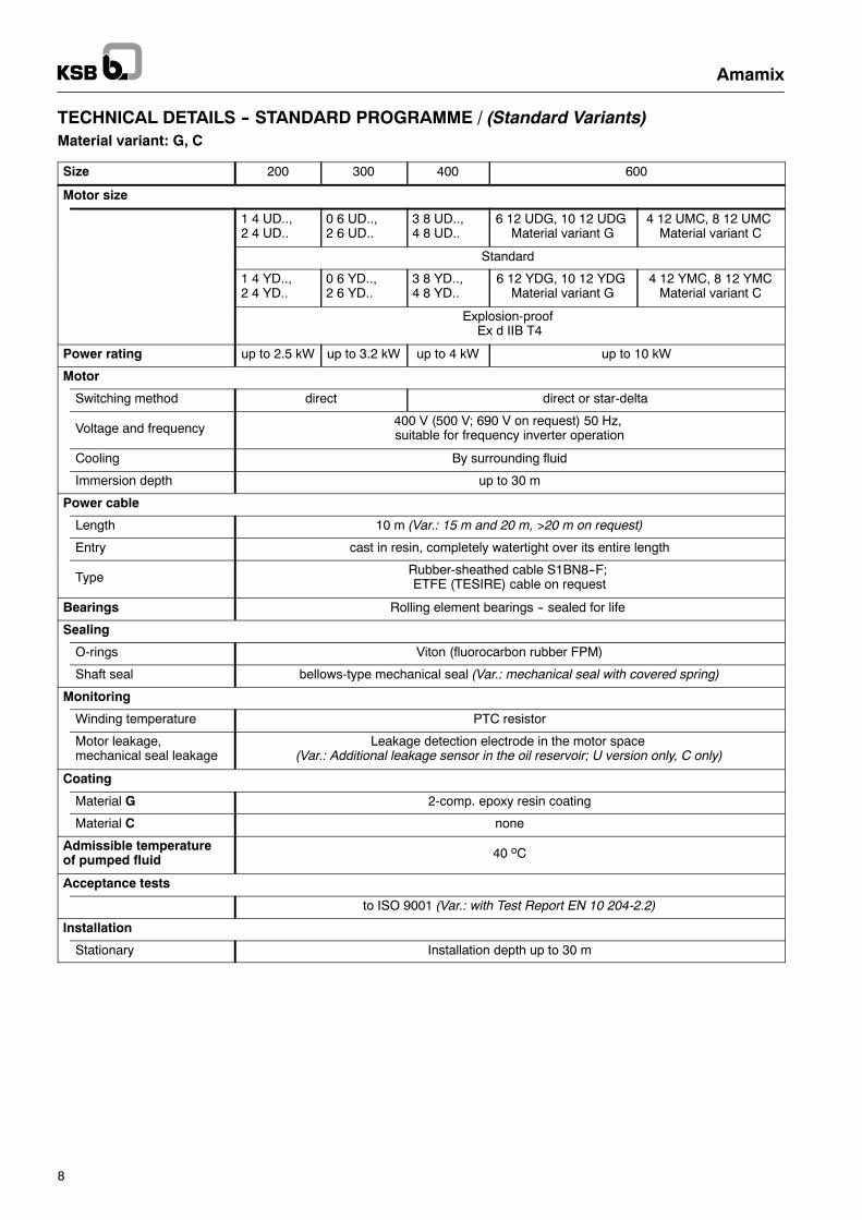
Motor housing cover
Propeller Shaft
Supportingclamp
Clamp
Motor housingCasing cover
UG 1117042
Jet ring
Adapter
Material variantPart Material variant
G C
Pump UnitMotor housing JL 1040 1.4581Motor housing cover JL 1040 1.4517Casing cover JL 1040 1.4571Adapter (except 200 G) PU
Propeller Amamix 200 PU(optional 1.4571) 1.4571
other sizes 1.4571
Mechanical sealpropeller side SiC/SiC
Mechanical sealmotor side SiC/SiC
Shaft 1.4571(Amamix 600 G in 1.4021)
O-rings Viton (FPM)Bolts A4 (as 1.4571)Clamp JL 1040 1.4571Supporting clamp 1.4571Jet ring (option) 1.4571Power cable EPR (optional ETFE)
Materials -- Information
Material comparisonEN Similar to ASTM material
JL 10 40 A 48 Class 40 B1.4517 A 890 CD 4 MCu1.4571 / 1.4581 A 276 Type 316 Ti1.4021 A 276 Type 420PU (Polyurethane) PolyurethaneFPM FKM
JL 1040 GG-25
Oil fill for mech. seal reservoirAmamix 200 G 0.3 lAmamix 200 C 0.4 lAmamix 300 G/C 0.4 lAmamix 400 G/C 0.8 lAmamix 600 G 2.4 lAmamix 600 C 1.4 l
Amamix
8
TECHNICAL DETAILS -- STANDARD PROGRAMME / (Standard Variants)Material variant: G, C
Size 200 300 400 600
Motor size
1 4 UD..,2 4 UD..
0 6 UD..,2 6 UD..
3 8 UD..,4 8 UD..
6 12 UDG, 10 12 UDGMaterial variant G
4 12 UMC, 8 12 UMCMaterial variant C
Standard
1 4 YD..,2 4 YD..
0 6 YD..,2 6 YD..
3 8 YD..,4 8 YD..
6 12 YDG, 10 12 YDGMaterial variant G
4 12 YMC, 8 12 YMCMaterial variant C
Explosion-proofEx d IIB T4
Power rating up to 2.5 kW up to 3.2 kW up to 4 kW up to 10 kW
Motor
Switching method direct direct or star-delta
Voltage and frequency400 V (500 V; 690 V on request) 50 Hz,suitable for frequency inverter operation
Cooling By surrounding fluid
Immersion depth up to 30 m
Power cable
Length 10 m (Var.: 15 m and 20 m, >20 m on request)
Entry cast in resin, completely watertight over its entire length
TypeRubber-sheathed cable S1BN8--F;ETFE (TESIRE) cable on request
Bearings Rolling element bearings -- sealed for life
Sealing
O-rings Viton (fluorocarbon rubber FPM)
Shaft seal bellows-type mechanical seal (Var.: mechanical seal with covered spring)
Monitoring
Winding temperature PTC resistor
Motor leakage,mechanical seal leakage
Leakage detection electrode in the motor space(Var.: Additional leakage sensor in the oil reservoir; U version only, C only)
Coating
Material G 2-comp. epoxy resin coating
Material C none
Admissible temperatureof pumped fluid 40 oC
Acceptance tests
to ISO 9001 (Var.: with Test Report EN 10 204-2.2)
Installation
Stationary Installation depth up to 30 m
Amamix
9
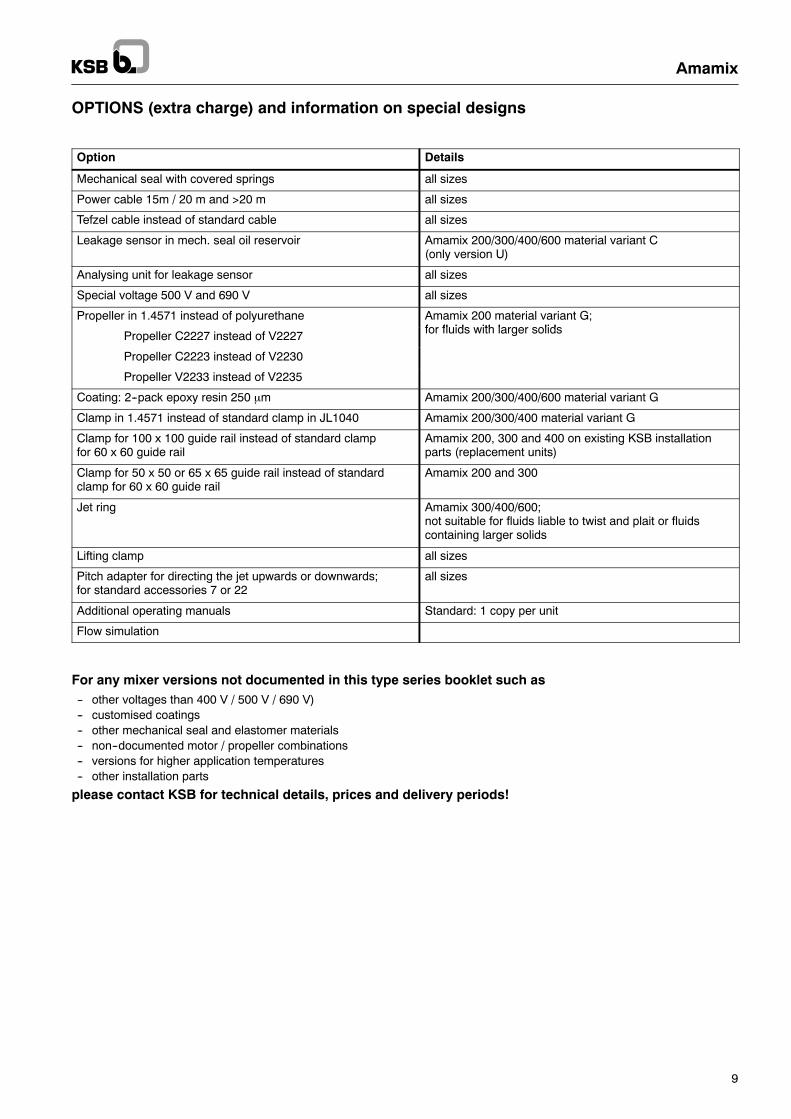
OPTIONS (extra charge) and information on special designs
Option Details
Mechanical seal with covered springs all sizes
Power cable 15m / 20 m and >20 m all sizes
Tefzel cable instead of standard cable all sizes
Leakage sensor in mech. seal oil reservoir Amamix 200/300/400/600 material variant C(only version U)
Analysing unit for leakage sensor all sizes
Special voltage 500 V and 690 V all sizes
Propeller in 1.4571 instead of polyurethane Amamix 200 material variant G;for fluids with larger solidsPropeller C2227 instead of V2227 for fluids with larger solids
Propeller C2223 instead of V2230
Propeller V2233 instead of V2235
Coating: 2--pack epoxy resin 250 μm Amamix 200/300/400/600 material variant G
Clamp in 1.4571 instead of standard clamp in JL1040 Amamix 200/300/400 material variant G
Clamp for 100 x 100 guide rail instead of standard clampfor 60 x 60 guide rail
Amamix 200, 300 and 400 on existing KSB installationparts (replacement units)
Clamp for 50 x 50 or 65 x 65 guide rail instead of standardclamp for 60 x 60 guide rail
Amamix 200 and 300
Jet ring Amamix 300/400/600;not suitable for fluids liable to twist and plait or fluidscontaining larger solids
Lifting clamp all sizes
Pitch adapter for directing the jet upwards or downwards;for standard accessories 7 or 22
all sizes
Additional operating manuals Standard: 1 copy per unit
Flow simulation
For any mixer versions not documented in this type series booklet such as-- other voltages than 400 V / 500 V / 690 V)-- customised coatings-- other mechanical seal and elastomer materials-- non--documented motor / propeller combinations-- versions for higher application temperatures-- other installation parts
please contact KSB for technical details, prices and delivery periods!
Amamix
10
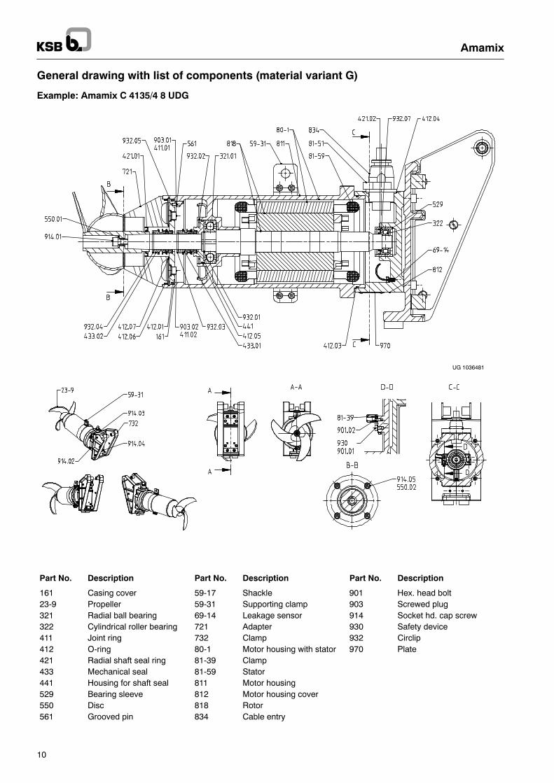
General drawing with list of components (material variant G)
Example: Amamix C 4135/4 8 UDG
UG 1036481
Part No. Description Part No. Description Part No. Description
161 Casing cover 59-17 Shackle 901 Hex. head bolt23-9 Propeller 59-31 Supporting clamp 903 Screwed plug321 Radial ball bearing 69-14 Leakage sensor 914 Socket hd. cap screw322 Cylindrical roller bearing 721 Adapter 930 Safety device411 Joint ring 732 Clamp 932 Circlip412 O-ring 80-1 Motor housing with stator 970 Plate421 Radial shaft seal ring 81-39 Clamp433 Mechanical seal 81-59 Stator441 Housing for shaft seal 811 Motor housing529 Bearing sleeve 812 Motor housing cover550 Disc 818 Rotor561 Grooved pin 834 Cable entry
Amamix
11
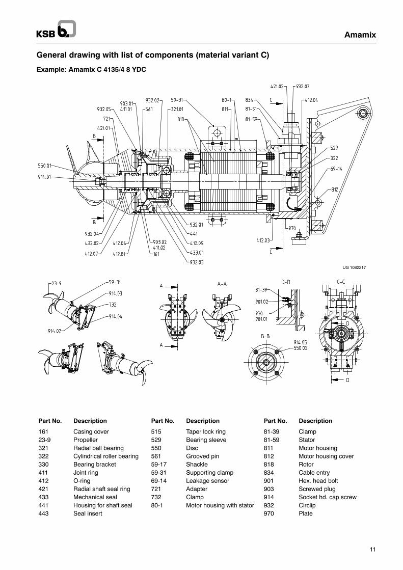
General drawing with list of components (material variant C)
Example: Amamix C 4135/4 8 YDC
UG 1082217
Part No. Description Part No. Description Part No. Description
161 Casing cover 515 Taper lock ring 81-39 Clamp23-9 Propeller 529 Bearing sleeve 81-59 Stator321 Radial ball bearing 550 Disc 811 Motor housing322 Cylindrical roller bearing 561 Grooved pin 812 Motor housing cover330 Bearing bracket 59-17 Shackle 818 Rotor411 Joint ring 59-31 Supporting clamp 834 Cable entry412 O-ring 69-14 Leakage sensor 901 Hex. head bolt421 Radial shaft seal ring 721 Adapter 903 Screwed plug433 Mechanical seal 732 Clamp 914 Socket hd. cap screw441 Housing for shaft seal 80-1 Motor housing with stator 932 Circlip443 Seal insert 970 Plate
Amamix
12
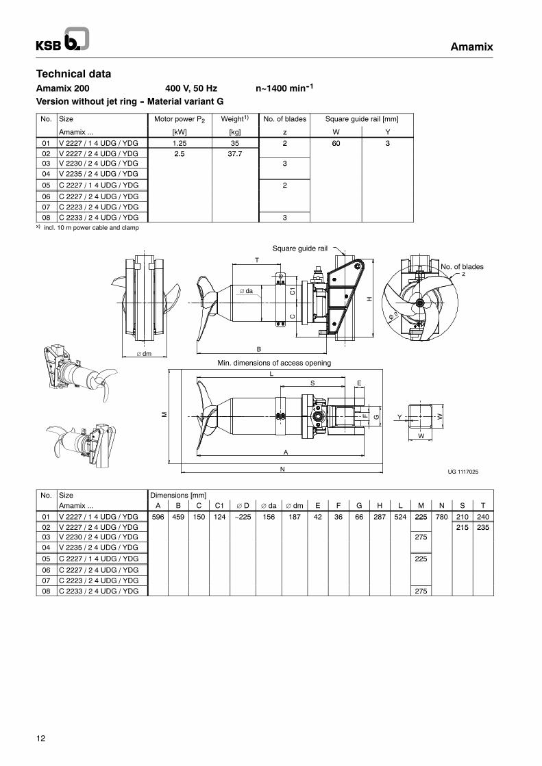
Technical dataAmamix 200 400 V, 50 Hz n~1400 min--1
Version without jet ring -- Material variant G
No. Size Motor power P2 Weight1) No. of blades Square guide rail [mm]
Amamix ... [kW] [kg] z W Y
01 V 2227 / 1 4 UDG / YDG 1.25 35 2 60 302 V 2227 / 2 4 UDG / YDG 2.5 37.7
2 60 3
03 V 2230 / 2 4 UDG / YDG2.5 37.7
304 V 2235 / 2 4 UDG / YDG
3
05 C 2227 / 1 4 UDG / YDG 2
06 C 2227 / 2 4 UDG / YDG
2
07 C 2223 / 2 4 UDG / YDG08 C 2233 / 2 4 UDG / YDG 3
x) incl. 10 m power cable and clamp
Min. dimensions of access opening
Square guide rail
No. of blades
UG 1117025
T
∅ da
∅ dm
H
CC
1
N
M
B
A
L
S EGF WY
W
z
No. Size Dimensions [mm]Amamix ... A B C C1 ∅ D ∅ da ∅ dm E F G H L M N S T
01 V 2227 / 1 4 UDG / YDG 596 459 150 124 ~225 156 187 42 36 66 287 524 225 780 210 24002 V 2227 / 2 4 UDG / YDG
225215 235
03 V 2230 / 2 4 UDG / YDG 275215 235
04 V 2235 / 2 4 UDG / YDG275
05 C 2227 / 1 4 UDG / YDG 225
06 C 2227 / 2 4 UDG / YDG
225
07 C 2223 / 2 4 UDG / YDG08 C 2233 / 2 4 UDG / YDG 275
Amamix
13
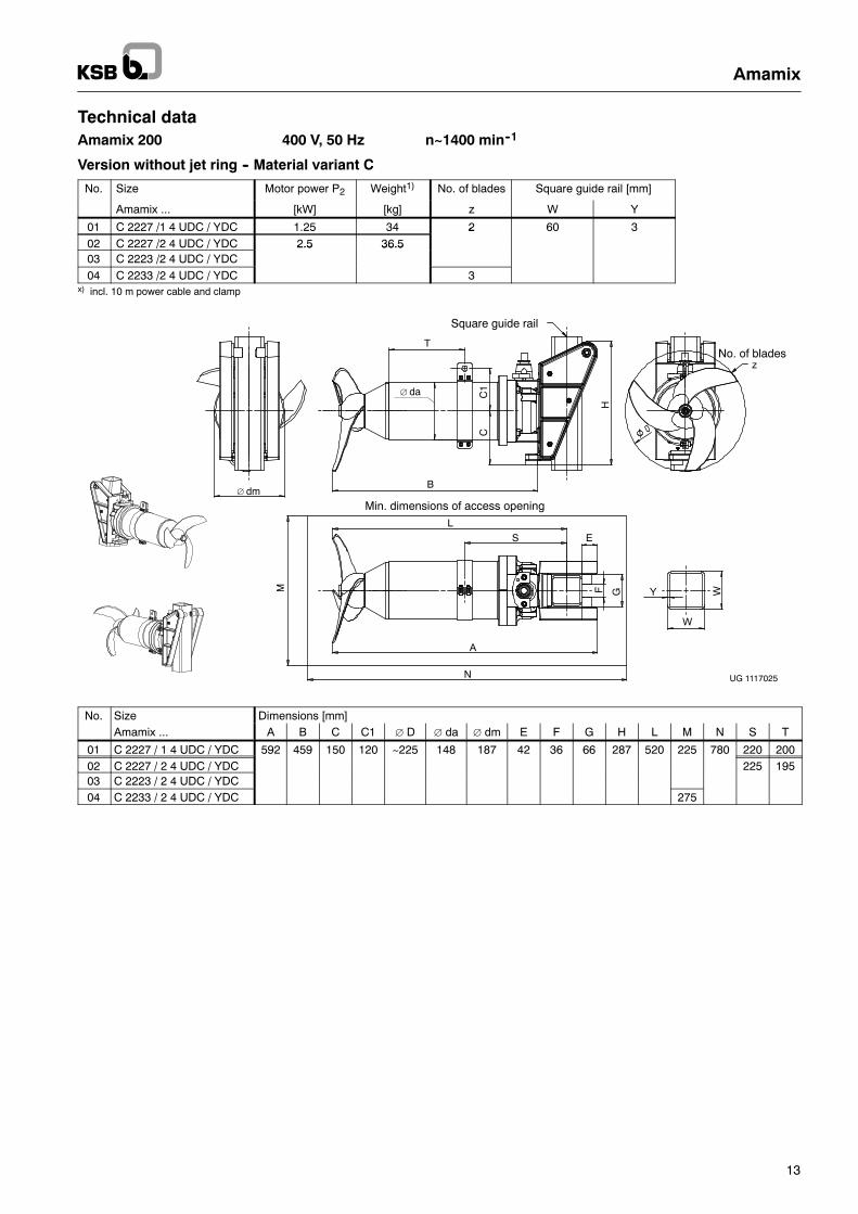
Technical dataAmamix 200 400 V, 50 Hz n~1400 min--1
Version without jet ring -- Material variant C
No. Size Motor power P2 Weight1) No. of blades Square guide rail [mm]
Amamix ... [kW] [kg] z W Y
01 C 2227 /1 4 UDC / YDC 1.25 34 2 60 302 C 2227 /2 4 UDC / YDC 2.5 36.5
2
03 C 2223 /2 4 UDC / YDC2.5 36.5
04 C 2233 /2 4 UDC / YDC 3x) incl. 10 m power cable and clamp
Min. dimensions of access opening
Square guide rail
No. of blades
UG 1117025
T
∅ da
∅ dm
H
CC
1
N
M
B
A
L
S E
GF WY
W
z
No. Size Dimensions [mm]Amamix ... A B C C1 ∅ D ∅ da ∅ dm E F G H L M N S T
01 C 2227 / 1 4 UDC / YDC 592 459 150 120 ~225 148 187 42 36 66 287 520 225 780 220 20002 C 2227 / 2 4 UDC / YDC 225 19503 C 2223 / 2 4 UDC / YDC04 C 2233 / 2 4 UDC / YDC 275
Amamix
14
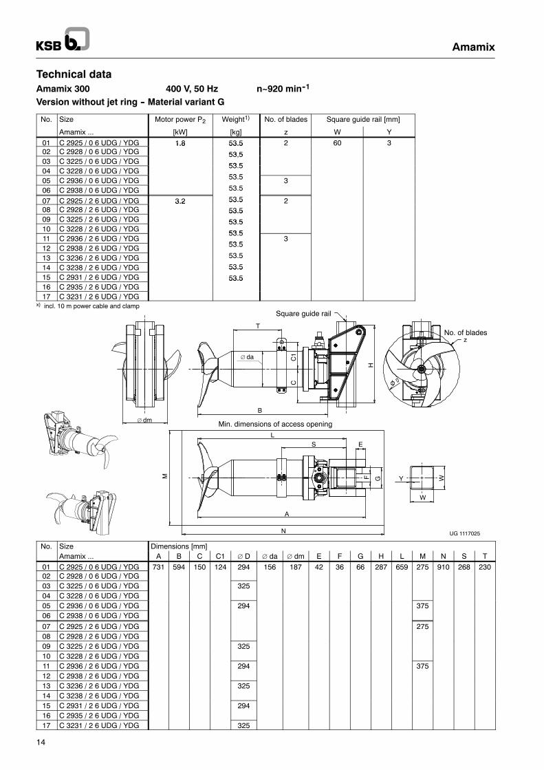
Technical dataAmamix 300 400 V, 50 Hz n~920 min--1
Version without jet ring -- Material variant G
No. Size Motor power P2 Weight1) No. of blades Square guide rail [mm]
Amamix ... [kW] [kg] z W Y
01 C 2925 / 0 6 UDG / YDG 1.8 53.5 2 60 302 C 2928 / 0 6 UDG / YDG
1.8 53.5
53 503 C 3225 / 0 6 UDG / YDG
53,5
53 504 C 3228 / 0 6 UDG / YDG
53.5
53 505 C 2936 / 0 6 UDG / YDG 53.5 306 C 2938 / 0 6 UDG / YDG 53.5
07 C 2925 / 2 6 UDG / YDG 3.2 53.5 208 C 2928 / 2 6 UDG / YDG
3.2 53.5
53.509 C 3225 / 2 6 UDG / YDG
53.5
53 510 C 3228 / 2 6 UDG / YDG
53.5
53 511 C 2936 / 2 6 UDG / YDG
53.5
53 53
12 C 2938 / 2 6 UDG / YDG 53.5
13 C 3236 / 2 6 UDG / YDG 53.5
14 C 3238 / 2 6 UDG / YDG 53.515 C 2931 / 2 6 UDG / YDG
53.5
53.516 C 2935 / 2 6 UDG / YDG
53.5
17 C 3231 / 2 6 UDG / YDGx) incl. 10 m power cable and clamp
Min. dimensions of access opening
Square guide rail
No. of blades
UG 1117025
T
∅ da
∅ dm
H
CC
1
N
M
B
A
L
S E
GF WY
W
z
No. Size Dimensions [mm]Amamix ... A B C C1 ∅ D ∅ da ∅ dm E F G H L M N S T
01 C 2925 / 0 6 UDG / YDG 731 594 150 124 294 156 187 42 36 66 287 659 275 910 268 23002 C 2928 / 0 6 UDG / YDG03 C 3225 / 0 6 UDG / YDG 32504 C 3228 / 0 6 UDG / YDG05 C 2936 / 0 6 UDG / YDG 294 37506 C 2938 / 0 6 UDG / YDG
07 C 2925 / 2 6 UDG / YDG 27508 C 2928 / 2 6 UDG / YDG09 C 3225 / 2 6 UDG / YDG 32510 C 3228 / 2 6 UDG / YDG11 C 2936 / 2 6 UDG / YDG 294 37512 C 2938 / 2 6 UDG / YDG13 C 3236 / 2 6 UDG / YDG 32514 C 3238 / 2 6 UDG / YDG15 C 2931 / 2 6 UDG / YDG 29416 C 2935 / 2 6 UDG / YDG17 C 3231 / 2 6 UDG / YDG 325
Amamix
15
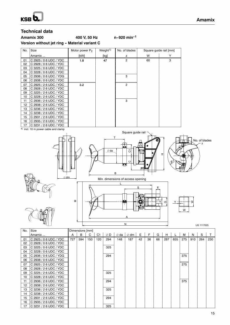
Technical dataAmamix 300 400 V, 50 Hz n~920 min--1
Version without jet ring -- Material variant C
No. Size Motor power P2 Weight1) No. of blades Square guide rail [mm]
Amamix ... [kW] [kg] z W Y
01 C 2925 / 0 6 UDC / YDC 1.8 47 2 60 302 C 2928 / 0 6 UDC / YDC
1.8 47
03 C 3225 / 0 6 UDC / YDC04 C 3228 / 0 6 UDC / YDC05 C 2936 / 0 6 UDC / YDG 306 C 2938 / 0 6 UDC / YDC07 C 2925 / 2 6 UDC / YDC 3.2 208 C 2928 / 2 6 UDC / YDC
3.2
09 C 3225 / 2 6 UDC / YDC10 C 3228 / 2 6 UDC / YDC11 C 2936 / 2 6 UDC / YDC 312 C 2938 / 2 6 UDC / YDC13 C 3236 / 2 6 UDC / YDC14 C 3238 / 2 6 UDC / YDC15 C 2931 / 2 6 UDC / YDC16 C 2935 / 2 6 UDC / YDC17 C 3231 / 2 6 UDC / YDC
x) incl. 10 m power cable and clamp
Min. dimensions of access opening
Square guide rail
No. of blades
UG 1117025
T
∅ da
∅ dm
H
CC
1
N
M
B
A
L
S E
GF WY
W
z
No. Size Dimensions [mm]Amamix ... A B C C1 ∅ D ∅ da ∅ dm E F G H L M N S T
01 C 2925 / 0 6 UDC / YDC 727 594 150 120 294 148 187 42 36 66 287 655 275 910 264 23002 C 2928 / 0 6 UDC / YDC03 C 3225 / 0 6 UDC / YDC 32504 C 3228 / 0 6 UDC / YDC05 C 2936 / 0 6 UDC / YDG 294 37506 C 2938 / 0 6 UDC / YDC
07 C 2925 / 2 6 UDC / YDC 27508 C 2928 / 2 6 UDC / YDC09 C 3225 / 2 6 UDC / YDC 32510 C 3228 / 2 6 UDC / YDC11 C 2936 / 2 6 UDC / YDC 294 37512 C 2938 / 2 6 UDC / YDC13 C 3236 / 2 6 UDC / YDC 32514 C 3238 / 2 6 UDC / YDC15 C 2931 / 2 6 UDC / YDC 29416 C 2935 / 2 6 UDC / YDC17 C 3231 / 2 6 UDC / YDC 325
Amamix
16
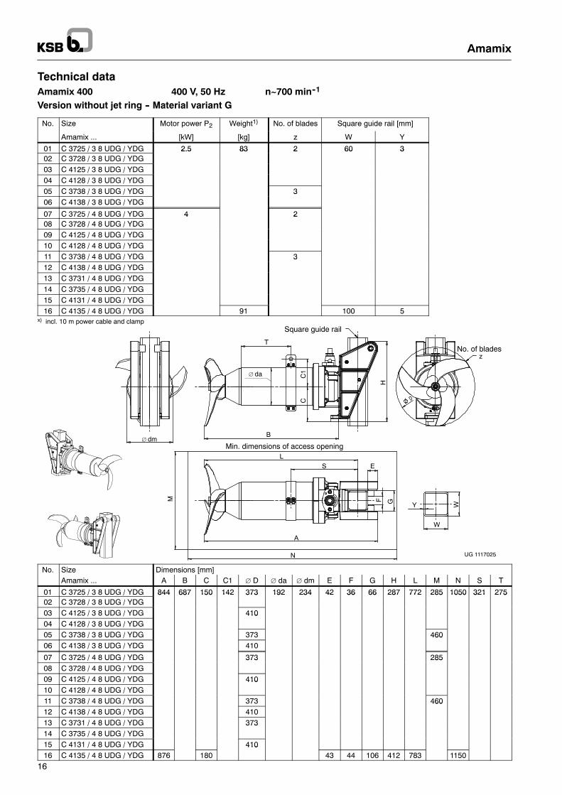
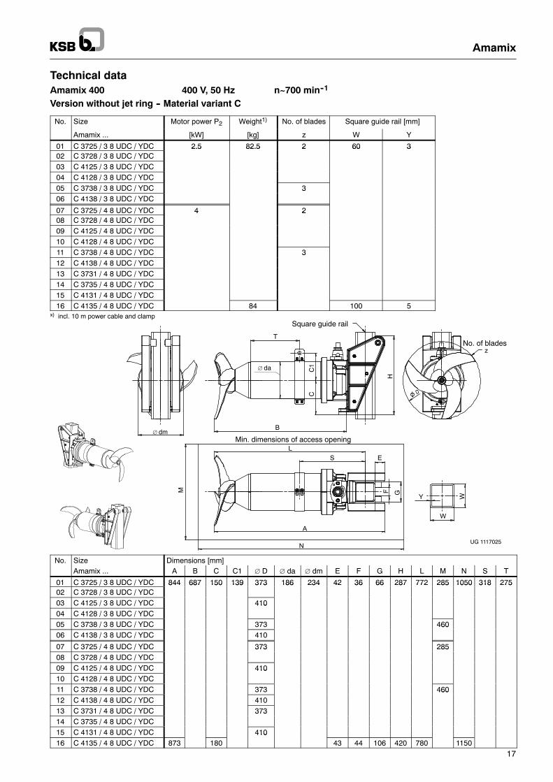
Technical dataAmamix 400 400 V, 50 Hz n~700 min--1
Version without jet ring -- Material variant G
No. Size Motor power P2 Weight1) No. of blades Square guide rail [mm]
Amamix ... [kW] [kg] z W Y
01 C 3725 / 3 8 UDG / YDG 2.5 83 2 60 302 C 3728 / 3 8 UDG / YDG
2.5 83 2 60 3
03 C 4125 / 3 8 UDG / YDG04 C 4128 / 3 8 UDG / YDG05 C 3738 / 3 8 UDG / YDG 306 C 4138 / 3 8 UDG / YDG
3
07 C 3725 / 4 8 UDG / YDG 4 208 C 3728 / 4 8 UDG / YDG
4 2
09 C 4125 / 4 8 UDG / YDG10 C 4128 / 4 8 UDG / YDG11 C 3738 / 4 8 UDG / YDG 312 C 4138 / 4 8 UDG / YDG
3
13 C 3731 / 4 8 UDG / YDG14 C 3735 / 4 8 UDG / YDG15 C 4131 / 4 8 UDG / YDG16 C 4135 / 4 8 UDG / YDG 91 100 5
x) incl. 10 m power cable and clamp
Min. dimensions of access opening
Square guide rail
No. of blades
UG 1117025
T
∅ da
∅ dm
H
CC
1
N
M
B
A
L
S E
GF
WY
W
z
No. Size Dimensions [mm]Amamix ... A B C C1 ∅ D ∅ da ∅ dm E F G H L M N S T
01 C 3725 / 3 8 UDG / YDG 844 687 150 142 373 192 234 42 36 66 287 772 285 1050 321 27502 C 3728 / 3 8 UDG / YDG
844 687 150 142 373 192 234 42 36 66 287 772 285 1050 321 275
03 C 4125 / 3 8 UDG / YDG 41004 C 4128 / 3 8 UDG / YDG
410
05 C 3738 / 3 8 UDG / YDG 373 46006 C 4138 / 3 8 UDG / YDG 410
460
07 C 3725 / 4 8 UDG / YDG 373 28508 C 3728 / 4 8 UDG / YDG
373 285
09 C 4125 / 4 8 UDG / YDG 41010 C 4128 / 4 8 UDG / YDG
410
11 C 3738 / 4 8 UDG / YDG 373 46012 C 4138 / 4 8 UDG / YDG 410
460
13 C 3731 / 4 8 UDG / YDG 37314 C 3735 / 4 8 UDG / YDG
373
15 C 4131 / 4 8 UDG / YDG 41016 C 4135 / 4 8 UDG / YDG 876 180
41043 44 106 412 783 1150
Amamix
17
Technical dataAmamix 400 400 V, 50 Hz n~700 min--1
Version without jet ring -- Material variant C
No. Size Motor power P2 Weight1) No. of blades Square guide rail [mm]
Amamix ... [kW] [kg] z W Y
01 C 3725 / 3 8 UDC / YDC 2.5 82.5 2 60 302 C 3728 / 3 8 UDC / YDC
2.5 82.5 2 60 3
03 C 4125 / 3 8 UDC / YDC04 C 4128 / 3 8 UDC / YDC05 C 3738 / 3 8 UDC / YDC 306 C 4138 / 3 8 UDC / YDC
3
07 C 3725 / 4 8 UDC / YDC 4 208 C 3728 / 4 8 UDC / YDC
4 2
09 C 4125 / 4 8 UDC / YDC10 C 4128 / 4 8 UDC / YDC11 C 3738 / 4 8 UDC / YDC 312 C 4138 / 4 8 UDC / YDC
3
13 C 3731 / 4 8 UDC / YDC14 C 3735 / 4 8 UDC / YDC15 C 4131 / 4 8 UDC / YDC16 C 4135 / 4 8 UDC / YDC 84 100 5
x) incl. 10 m power cable and clamp
Min. dimensions of access opening
Square guide rail
No. of blades
UG 1117025
T
∅ da
∅ dm
H
CC
1
N
M
B
A
L
S E
GF
WY
W
z
No. Size Dimensions [mm]Amamix ... A B C C1 ∅ D ∅ da ∅ dm E F G H L M N S T
01 C 3725 / 3 8 UDC / YDC 844 687 150 139 373 186 234 42 36 66 287 772 285 1050 318 27502 C 3728 / 3 8 UDC / YDC
844 687 150 139 373 186 234 42 36 66 287 772 285 1050 318 275
03 C 4125 / 3 8 UDC / YDC 41004 C 4128 / 3 8 UDC / YDC
410
05 C 3738 / 3 8 UDC / YDC 373 46006 C 4138 / 3 8 UDC / YDC 410
460
07 C 3725 / 4 8 UDC / YDC 373 28508 C 3728 / 4 8 UDC / YDC
373 285
09 C 4125 / 4 8 UDC / YDC 41010 C 4128 / 4 8 UDC / YDC
410
11 C 3738 / 4 8 UDC / YDC 373 46012 C 4138 / 4 8 UDC / YDC 410
460
13 C 3731 / 4 8 UDC / YDC 37314 C 3735 / 4 8 UDC / YDC
373
15 C 4131 / 4 8 UDC / YDC 41016 C 4135 / 4 8 UDC / YDC 873 180
41043 44 106 420 780 1150
Amamix
18
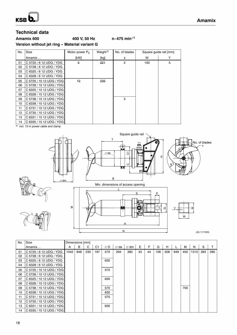
Technical dataAmamix 600 400 V, 50 Hz n~475 min--1
Version without jet ring -- Material variant G
No. Size Motor power P2 Weight1) No. of blades Square guide rail [mm]
Amamix ... [kW] [kg] z W Y
01 C 5725 / 6 12 UDG / YDG 5 221 2 100 502 C 5728 / 6 12 UDG / YDG
5 221
03 C 6325 / 6 12 UDG / YDG04 C 6328 / 6 12 UDG / YDG
05 C 5725 / 10 12 UDG / YDG 10 23506 C 5728 / 10 12 UDG / YDG
10 235
07 C 6325 / 10 12 UDG / YDG08 C 6328 / 10 12 UDG / YDG09 C 5738 / 10 12 UDG / YDG 310 C 6338 / 10 12 UDG / YDG11 C 5731 / 10 12 UDG / YDG12 C 5735 / 10 12 UDG / YDG13 C 6331 / 10 12 UDG / YDG14 C 6335 / 10 12 UDG / YDG
x) incl. 10 m power cable and clamp
Min. dimensions of access opening
Square guide rail
No. of blades
UG 1117025
T
∅ da
∅ dm
H
CC
1
N
M
B
A
L
S E
GF WY
W
z
No. Size Dimensions [mm]Amamix ... A B C C1 ∅ D ∅ da ∅ dm E F G H L M N S T
01 C 5725 / 6 12 UDG / YDG 1042 848 230 197 570 294 380 43 44 106 508 949 450 1310 393 28002 C 5728 / 6 12 UDG / YDG03 C 6325 / 6 12 UDG / YDG 63004 C 6328 / 6 12 UDG / YDG
05 C 5725 / 10 12 UDG / YDG 57006 C 5728 / 10 12 UDG / YDG07 C 6325 / 10 12 UDG / YDG 63008 C 6328 / 10 12 UDG / YDG09 C 5738 / 10 12 UDG / YDG 570 70010 C 6338 / 10 12 UDG / YDG 63011 C 5731 / 10 12 UDG / YDG 57012 C 5735 / 10 12 UDG / YDG13 C 6331 / 10 12 UDG / YDG 63014 C 6335 / 10 12 UDG / YDG
Amamix
19
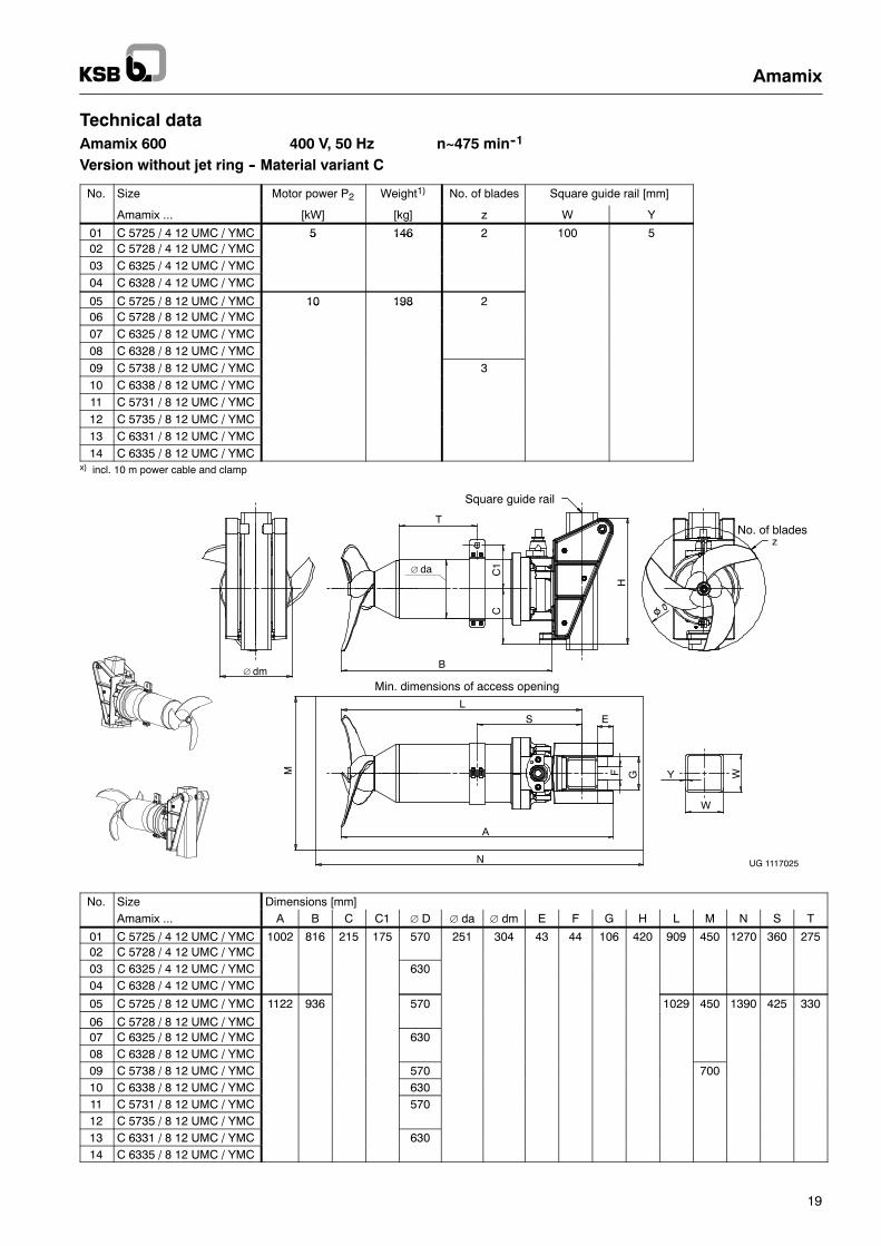
Technical dataAmamix 600 400 V, 50 Hz n~475 min--1
Version without jet ring -- Material variant C
No. Size Motor power P2 Weight1) No. of blades Square guide rail [mm]
Amamix ... [kW] [kg] z W Y
01 C 5725 / 4 12 UMC / YMC 5 146 2 100 502 C 5728 / 4 12 UMC / YMC
5 146
03 C 6325 / 4 12 UMC / YMC04 C 6328 / 4 12 UMC / YMC
05 C 5725 / 8 12 UMC / YMC 10 198 206 C 5728 / 8 12 UMC / YMC
10 198
07 C 6325 / 8 12 UMC / YMC08 C 6328 / 8 12 UMC / YMC09 C 5738 / 8 12 UMC / YMC 310 C 6338 / 8 12 UMC / YMC11 C 5731 / 8 12 UMC / YMC12 C 5735 / 8 12 UMC / YMC13 C 6331 / 8 12 UMC / YMC14 C 6335 / 8 12 UMC / YMC
x) incl. 10 m power cable and clamp
Min. dimensions of access opening
Square guide rail
No. of blades
UG 1117025
T
∅ da
∅ dm
H
CC
1
N
M
B
A
L
S E
GF WY
W
z
No. Size Dimensions [mm]Amamix ... A B C C1 ∅ D ∅ da ∅ dm E F G H L M N S T
01 C 5725 / 4 12 UMC / YMC 1002 816 215 175 570 251 304 43 44 106 420 909 450 1270 360 27502 C 5728 / 4 12 UMC / YMC03 C 6325 / 4 12 UMC / YMC 63004 C 6328 / 4 12 UMC / YMC
05 C 5725 / 8 12 UMC / YMC 1122 936 570 1029 450 1390 425 330
06 C 5728 / 8 12 UMC / YMC07 C 6325 / 8 12 UMC / YMC 63008 C 6328 / 8 12 UMC / YMC09 C 5738 / 8 12 UMC / YMC 570 70010 C 6338 / 8 12 UMC / YMC 63011 C 5731 / 8 12 UMC / YMC 57012 C 5735 / 8 12 UMC / YMC13 C 6331 / 8 12 UMC / YMC 63014 C 6335 / 8 12 UMC / YMC
Amamix
20
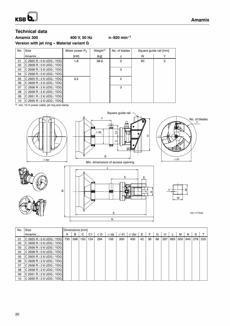
Technical dataAmamix 300 400 V, 50 Hz n~920 min--1
Version with jet ring -- Material variant G
No. Size Motor power P2 Weight1) No. of blades Square guide rail [mm]
Amamix ... [kW] [kg] z W Y
01 C 2925 R / 0 6 UDG / YDG 1.8 58.2 2 60 302 C 2928 R / 0 6 UDG / YDG
1.8 58.2
03 C 2936 R / 0 6 UDG / YDG 304 C 2938 R / 0 6 UDG / YDG
05 C 2925 R / 2 6 UDG / YDG 3.2 206 C 2928 R / 2 6 UDG / YDG
3.2
07 C 2936 R / 2 6 UDG / YDG 308 C 2938 R / 2 6 UDG / YDG09 C 2931 R / 2 6 UDG / YDG10 C 2935 R / 2 6 UDG / YDG
x) incl. 10 m power cable, jet ring and clamp
UG 1117042
Min. dimensions of access opening
T
H
CC
1
B
Square guide rail
∅ dsr
WY
W
N
M
A
L
S E
GF
∅ da
No. of bladesz
∅ d1
∅ D
No. Size Dimensions [mm]Amamix ... A B C C1 ∅ D ∅ da ∅ d1 ∅ dsr E F G H L M N S T
01 C 2925 R / 0 6 UDG / YDG 735 598 150 124 294 156 300 400 42 36 66 287 663 500 945 278 22002 C 2928 R / 0 6 UDG / YDG03 C 2936 R / 0 6 UDG / YDG04 C 2938 R / 0 6 UDG / YDG
05 C 2925 R / 2 6 UDG / YDG06 C 2928 R / 2 6 UDG / YDG07 C 2936 R / 2 6 UDG / YDG08 C 2938 R / 2 6 UDG / YDG09 C 2931 R / 2 6 UDG / YDG10 C 2935 R / 2 6 UDG / YDG
Amamix
21
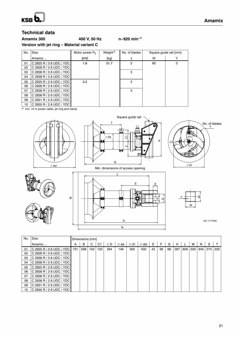
Technical dataAmamix 300 400 V, 50 Hz n~920 min--1
Version with jet ring -- Material variant C
No. Size Motor power P2 Weight1) No. of blades Square guide rail [mm]
Amamix ... [kW] [kg] z W Y
01 C 2925 R / 0 6 UDC / YDC 1.8 51.7 2 60 302 C 2928 R / 0 6 UDC / YDC
1.8 51.7
03 C 2936 R / 0 6 UDC / YDC 304 C 2938 R / 0 6 UDC / YDC
05 C 2925 R / 2 6 UDC / YDC 3.2 206 C 2928 R / 2 6 UDC / YDC
3.2
07 C 2936 R / 2 6 UDC / YDC 308 C 2938 R / 2 6 UDC / YDC09 C 2931 R / 2 6 UDC / YDC10 C 2935 R / 2 6 UDC / YDC
x) incl. 10 m power cable, jet ring and clamp
UG 1117042
Min. dimensions of access opening
T
H
CC
1
B
Square guide rail
∅ dsr
WY
W
N
M
A
L
S E
GF
∅ da
No. of bladesz
∅ d1
∅ D
No. Size Dimensions [mm]
Amamix ... A B C C1 ∅ D ∅ da ∅ d1 ∅ dsr E F G H L M N S T
01 C 2925 R / 0 6 UDC / YDC 731 598 150 120 294 148 300 400 42 36 66 287 659 500 945 274 22002 C 2928 R / 0 6 UDC / YDC03 C 2936 R / 0 6 UDC / YDC04 C 2938 R / 0 6 UDC / YDC
05 C 2925 R / 2 6 UDC / YDC06 C 2928 R / 2 6 UDC / YDC07 C 2936 R / 2 6 UDC / YDC08 C 2938 R / 2 6 UDC / YDC09 C 2931 R / 2 6 UDC / YDC10 C 2935 R / 2 6 UDC / YDC
Amamix
22
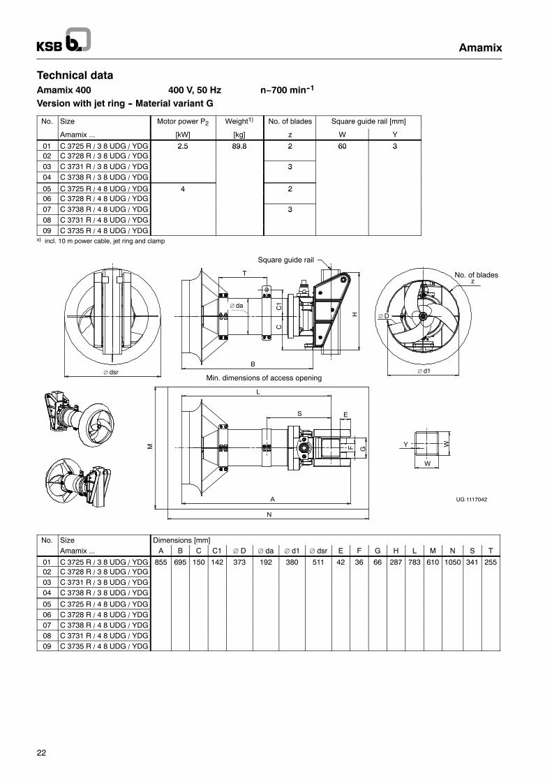
Technical dataAmamix 400 400 V, 50 Hz n~700 min--1
Version with jet ring -- Material variant G
No. Size Motor power P2 Weight1) No. of blades Square guide rail [mm]
Amamix ... [kW] [kg] z W Y
01 C 3725 R / 3 8 UDG / YDG 2.5 89.8 2 60 302 C 3728 R / 3 8 UDG / YDG
2.5 89.8 2 60 3
03 C 3731 R / 3 8 UDG / YDG 304 C 3738 R / 3 8 UDG / YDG
3
05 C 3725 R / 4 8 UDG / YDG 4 206 C 3728 R / 4 8 UDG / YDG
4 2
07 C 3738 R / 4 8 UDG / YDG 308 C 3731 R / 4 8 UDG / YDG
3
09 C 3735 R / 4 8 UDG / YDGx) incl. 10 m power cable, jet ring and clamp
UG 1117042
Min. dimensions of access opening
T
H
CC
1
B
Square guide rail
∅ dsr
WY
W
N
M
A
L
S E
GF
∅ da
No. of bladesz
∅ d1
∅ D
No. Size Dimensions [mm]Amamix ... A B C C1 ∅ D ∅ da ∅ d1 ∅ dsr E F G H L M N S T
01 C 3725 R / 3 8 UDG / YDG 855 695 150 142 373 192 380 511 42 36 66 287 783 610 1050 341 25502 C 3728 R / 3 8 UDG / YDG03 C 3731 R / 3 8 UDG / YDG04 C 3738 R / 3 8 UDG / YDG
05 C 3725 R / 4 8 UDG / YDG06 C 3728 R / 4 8 UDG / YDG07 C 3738 R / 4 8 UDG / YDG08 C 3731 R / 4 8 UDG / YDG09 C 3735 R / 4 8 UDG / YDG
Amamix
23
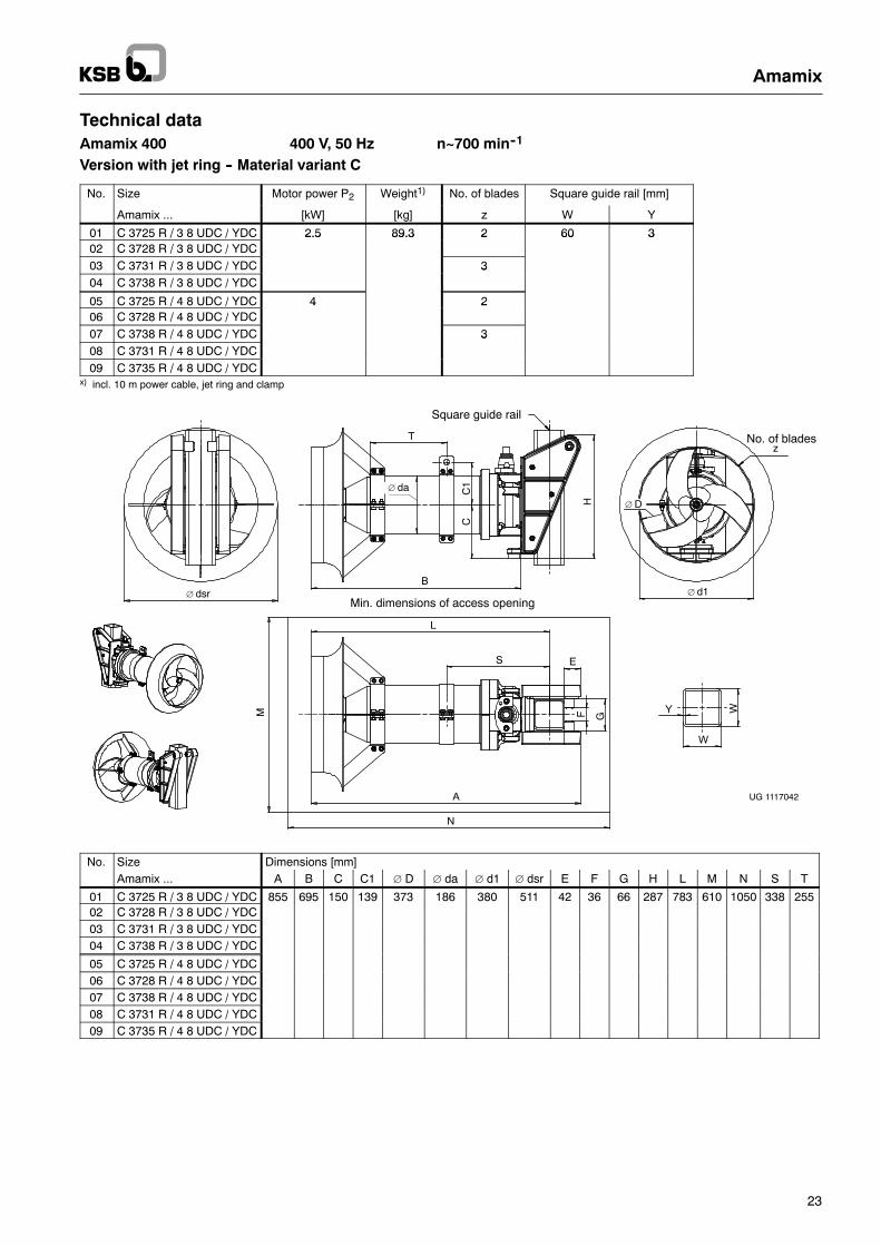
Technical dataAmamix 400 400 V, 50 Hz n~700 min--1
Version with jet ring -- Material variant C
No. Size Motor power P2 Weight1) No. of blades Square guide rail [mm]
Amamix ... [kW] [kg] z W Y
01 C 3725 R / 3 8 UDC / YDC 2.5 89.3 2 60 302 C 3728 R / 3 8 UDC / YDC
2.5 89.3 2 60 3
03 C 3731 R / 3 8 UDC / YDC 304 C 3738 R / 3 8 UDC / YDC
3
05 C 3725 R / 4 8 UDC / YDC 4 206 C 3728 R / 4 8 UDC / YDC
4 2
07 C 3738 R / 4 8 UDC / YDC 308 C 3731 R / 4 8 UDC / YDC
3
09 C 3735 R / 4 8 UDC / YDCx) incl. 10 m power cable, jet ring and clamp
UG 1117042
Min. dimensions of access opening
T
H
CC
1
B
Square guide rail
∅ dsr
WY
W
N
M
A
L
S E
GF
∅ da
No. of bladesz
∅ d1
∅ D
No. Size Dimensions [mm]Amamix ... A B C C1 ∅ D ∅ da ∅ d1 ∅ dsr E F G H L M N S T
01 C 3725 R / 3 8 UDC / YDC 855 695 150 139 373 186 380 511 42 36 66 287 783 610 1050 338 25502 C 3728 R / 3 8 UDC / YDC03 C 3731 R / 3 8 UDC / YDC04 C 3738 R / 3 8 UDC / YDC
05 C 3725 R / 4 8 UDC / YDC06 C 3728 R / 4 8 UDC / YDC07 C 3738 R / 4 8 UDC / YDC08 C 3731 R / 4 8 UDC / YDC09 C 3735 R / 4 8 UDC / YDC

Amamix
24
Technical dataAmamix 600 400 V, 50 Hz n~475 min--1
Version with jet ring -- Material variant G
No. Size Motor power P2 Weight1) No. of blades Square guide rail [mm]
Amamix ... [kW] [kg] z W Y
01 C 5725 R / 6 12 UDG / YDG 5 240.5 2 100 502 C 5728 R / 6 12 UDG / YDG
5 240.5
03 C 5731 R / 6 12 UDG / YDG 304 C 5738 R / 6 12 UDG / YDG
05 C 5725 R / 10 12 UDG / YDG 10 254.5 206 C 5728 R / 10 12 UDG / YDG
10 254.5
07 C 5738 R / 10 12 UDG / YDG 308 C 5731 R / 10 12 UDG / YDG09 C 5735 R / 10 12 UDG / YDG
x) incl. 10 m power cable, jet ring and clamp
UG 1117042
Min. dimensions of access opening
T
H
CC
1
B
Square guide rail
∅ dsr
WY
W
N
M
A
L
S E
GF
∅ da
No. of bladesz
∅ d1
∅ D
No. Size Dimensions [mm]Amamix ... A B C C1 ∅ D ∅ da ∅ d1 ∅ dsr E F G H L M N S T
01 C 5725 R / 6 12 UDG / YDG 1048 854 230 197 570 294 580 773 54 44 106 507 953 875 1335 403 27002 C 5728 R / 6 12 UDG / YDG03 C 5731 R / 6 12 UDG / YDG04 C 5738 R / 6 12 UDG / YDG
05 C 5725 R / 10 12 UDG / YDG06 C 5728 R / 10 12 UDG / YDG07 C 5738 R / 10 12 UDG / YDG08 C 5731 R / 10 12 UDG / YDG09 C 5735 R / 10 12 UDG / YDG

Amamix
25
Technical dataAmamix 600 400 V, 50 Hz n~475 min--1
Version with jet ring -- Material variant C
No. Size Motor power P2 Weight1) No. of blades Square guide rail [mm]
Amamix ... [kW] [kg] z W Y
01 C 5725 R / 4 12 UMC / YMC 5 165.5 2 100 502 C 5728 R / 4 12 UMC / YMC
5 165.5
03 C 5731 R / 4 12 UMC / YMC 304 C 5738 R / 4 12 UMC / YMC
05 C 5725 R / 8 12 UMC / YMC 10 217.5 206 C 5728 R / 8 12 UMC / YMC
10 217.5
07 C 5738 R / 8 12 UMC / YMC 308 C 5731 R / 8 12 UMC / YMC09 C 5735 R / 8 12 UMC / YMC
x) incl. 10 m power cable, jet ring and clamp
UG 1117042
Min. dimensions of access opening
T
H
CC
1
B
Square guide rail
∅ dsr
WY
W
N
M
A
L
S E
GF
∅ da
No. of bladesz
∅ d1
∅ D
No. Size Dimensions [mm]Amamix ... A B C C1 ∅ D ∅ da ∅ d1 ∅ dsr E F G H L M N S T
01 C 5725 R / 4 12 UMC / YMC 1016 830 215 176 570 251 580 773 43 44 106 420 908 890 1290 380 25002 C 5728 R / 4 12 UMC / YMC03 C 5731 R / 4 12 UMC / YMC04 C 5738 R / 4 12 UMC / YMC
05 C 5725 R/ 8 12 UMC / YMC 1137 950 1028 1410 445 31006 C 5728 R / 8 12 UMC / YMC07 C 5738 R / 8 12 UMC / YMC08 C 5731 R / 8 12 UMC / YMC09 C 5735 R / 8 12 UMC / YMC

Amamix
26
Amamix
27
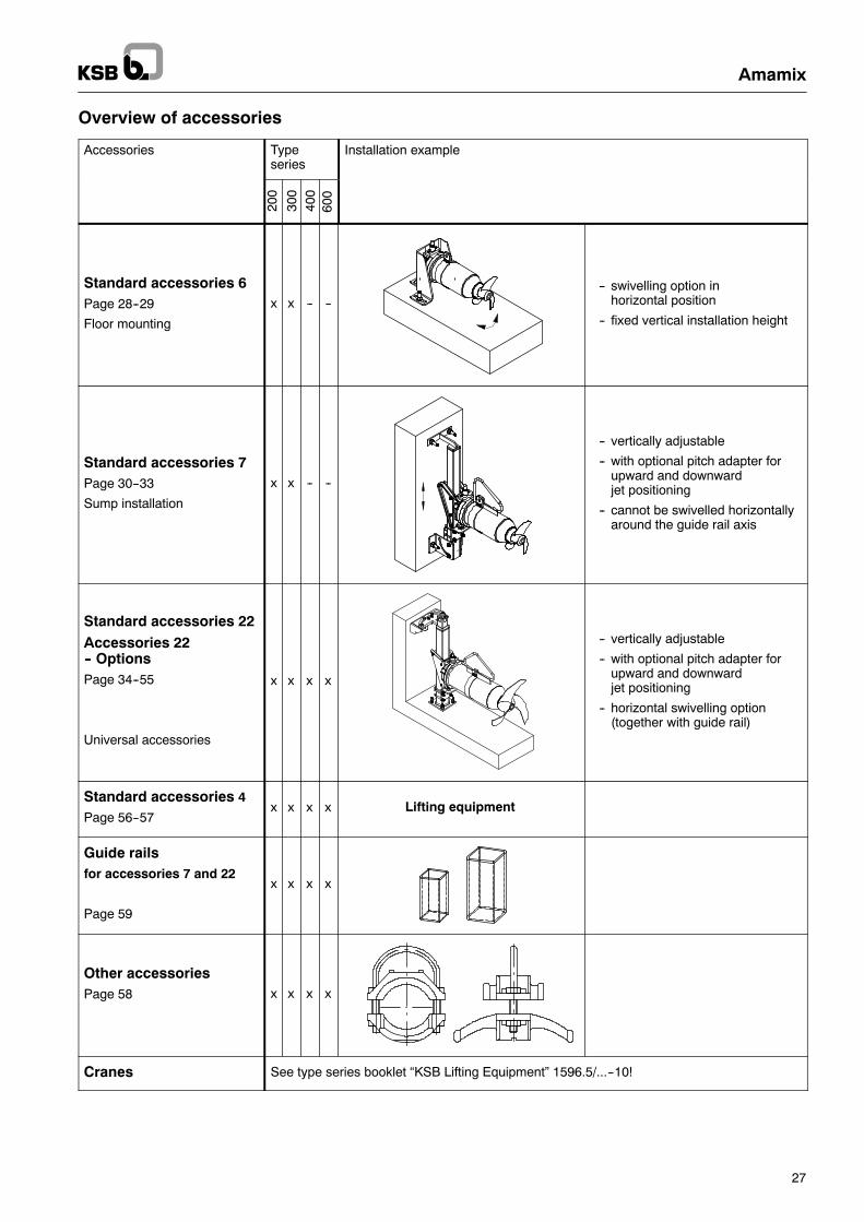
Overview of accessories
Accessories Typeseries
Installation example
200
300
400
600
Standard accessories 6Page 28--29
Floor mounting
x x -- ---- swivelling option in
horizontal position
-- fixed vertical installation height
Standard accessories 7Page 30--33
Sump installation
x x -- --
-- vertically adjustable
-- with optional pitch adapter forupward and downwardjet positioning
-- cannot be swivelled horizontallyaround the guide rail axis
Standard accessories 22Accessories 22-- OptionsPage 34--55
Universal accessories
x x x x
-- vertically adjustable
-- with optional pitch adapter forupward and downwardjet positioning
-- horizontal swivelling option(together with guide rail)
Standard accessories 4
Page 56--57x x x x Lifting equipment
Guide railsfor accessories 7 and 22
Page 59
x x x x
Other accessoriesPage 58 x x x x
Cranes See type series booklet “KSB Lifting Equipment” 1596.5/...--10!
Amamix
28
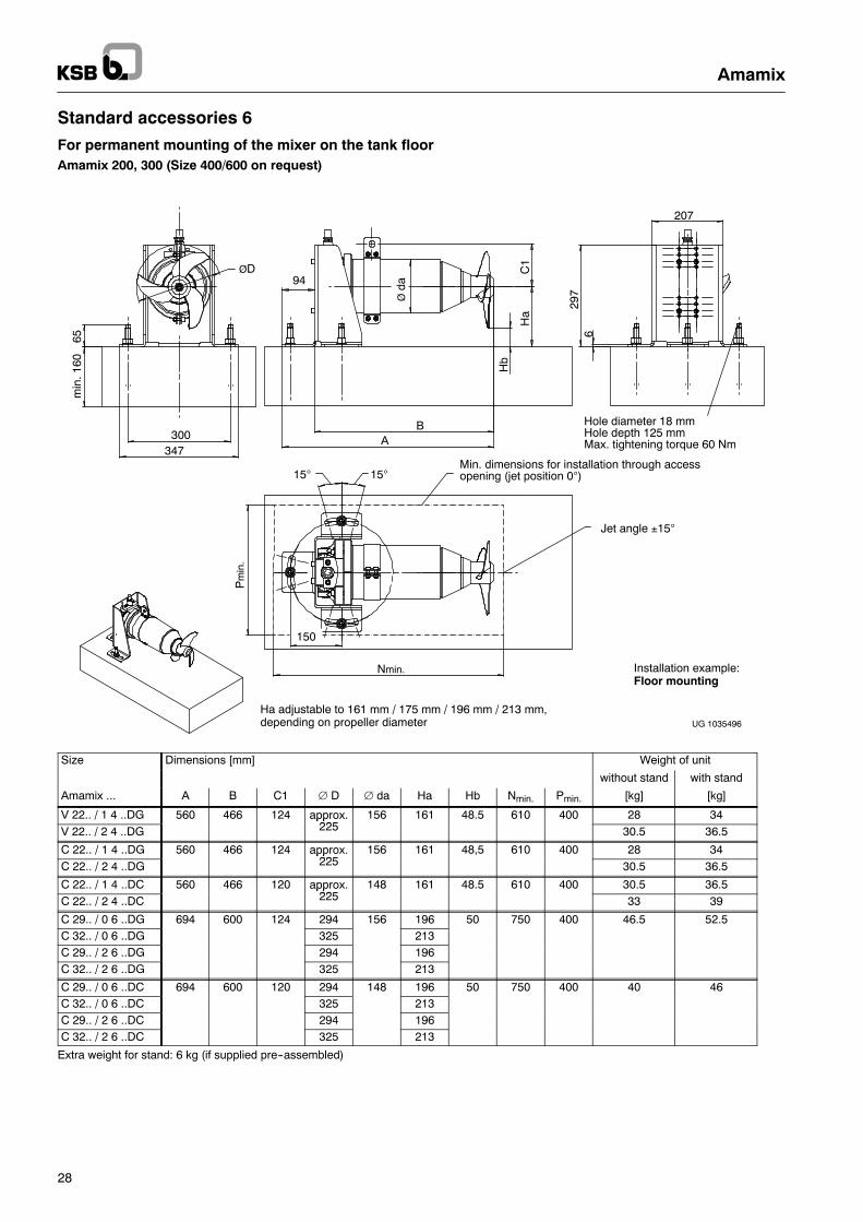
Standard accessories 6
For permanent mounting of the mixer on the tank floorAmamix 200, 300 (Size 400/600 on request)
Hole diameter 18 mmHole depth 125 mmMax. tightening torque 60 Nm
Ha adjustable to 161 mm / 175 mm / 196 mm / 213 mm,depending on propeller diameter
Installation example:Floor mounting
UG 1035496
629
7
207
AB
94
C1
Ha
Hb
Øda
min
.160
65
300347
ØD
Nmin.
150
Pm
in.
15°15°Min. dimensions for installation through accessopening (jet position 0°)
Jet angle ±15°
Size Dimensions [mm] Weight of unit
without stand with stand
Amamix ... A B C1 ∅ D ∅ da Ha Hb Nmin. Pmin. [kg] [kg]
V 22.. / 1 4 ..DG 560 466 124 approx.225
156 161 48.5 610 400 28 34V 22.. / 2 4 ..DG
pp225 30.5 36.5
C 22.. / 1 4 ..DG 560 466 124 approx.225
156 161 48,5 610 400 28 34C 22.. / 2 4 ..DG
pp225 30.5 36.5
C 22.. / 1 4 ..DC 560 466 120 approx.225
148 161 48.5 610 400 30.5 36.5C 22.. / 2 4 ..DC
pp225 33 39
C 29.. / 0 6 ..DG 694 600 124 294 156 196 50 750 400 46.5 52.5C 32.. / 0 6 ..DG 325 213C 29.. / 2 6 ..DG 294 196C 32.. / 2 6 ..DG 325 213
C 29.. / 0 6 ..DC 694 600 120 294 148 196 50 750 400 40 46C 32.. / 0 6 ..DC 325 213C 29.. / 2 6 ..DC 294 196C 32.. / 2 6 ..DC 325 213
Extra weight for stand: 6 kg (if supplied pre--assembled)
Amamix
29
Standard accessories 6
For permanent mounting of the mixer on the tank floorAmamix 200, 300
Item No. Accessories Description
6 Stand for permanent mounting of the mixer (sizes 200, 300) on the tank floor;application in tanks where regular drainage provides access to the unit(e.g. for maintenance and inspection purposes),e.g. stormwater balancing systems.
Incl. composite anchorbolts
Composite anchor bolts for fastening the stand on the tank floor(concrete grade at least B25)
Item No. Description For size Material Material No. Weight[kg]
6 Standincl 3 nos composite anchor bolts
Amamix 200/300 1.4301 01 109 062 8.0incl. 3 nos. composite anchor bolts
1.4571 19 556 921 8.0
Amamix
30
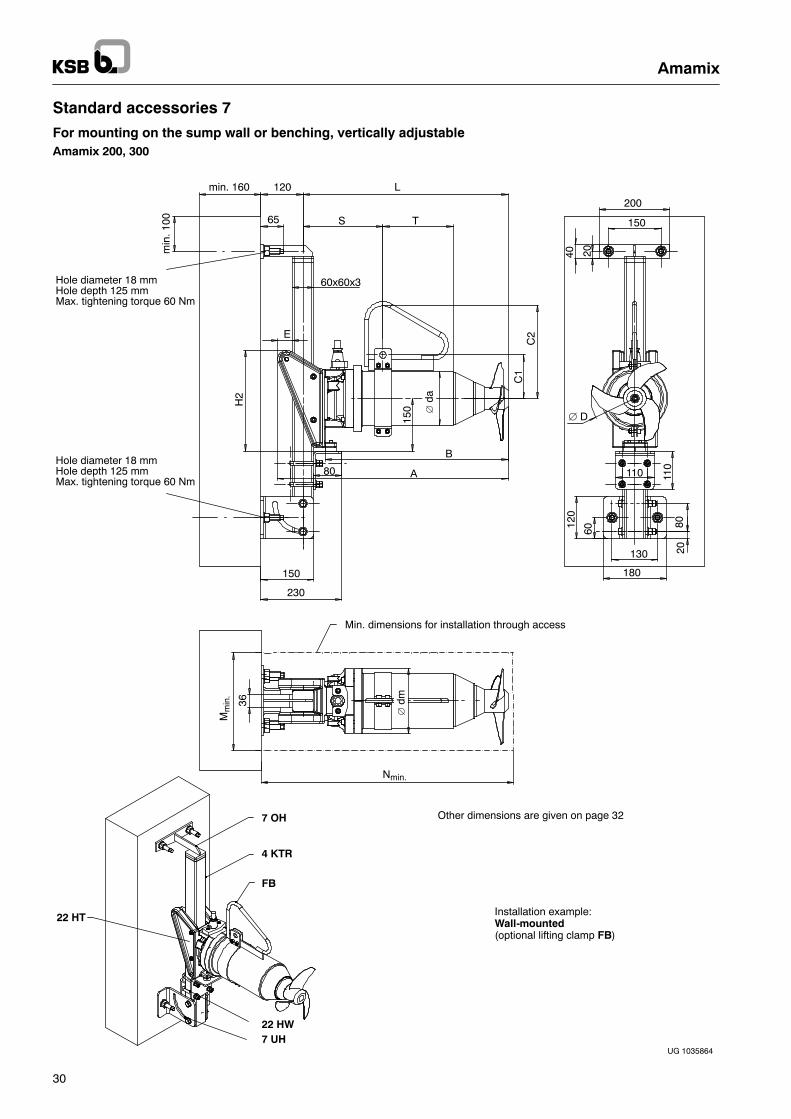
Standard accessories 7
For mounting on the sump wall or benching, vertically adjustableAmamix 200, 300
UG 1035864
7 OH
4 KTR
FB
22 HW7 UH
40
200
150
C1
C2
∅ D
120
60
130
180
110 110
8020
20min
.100
120
60x60x3
H2
150
230
80
∅da
A
B
150
min. 160
65 S T
L
E
22 HT
Hole diameter 18 mmHole depth 125 mmMax. tightening torque 60 Nm
Hole diameter 18 mmHole depth 125 mmMax. tightening torque 60 Nm
Min. dimensions for installation through access
Other dimensions are given on page 32
Installation example:Wall-mounted(optional lifting clamp FB)
∅dm
Mm
in.
Nmin.
36
Amamix
31
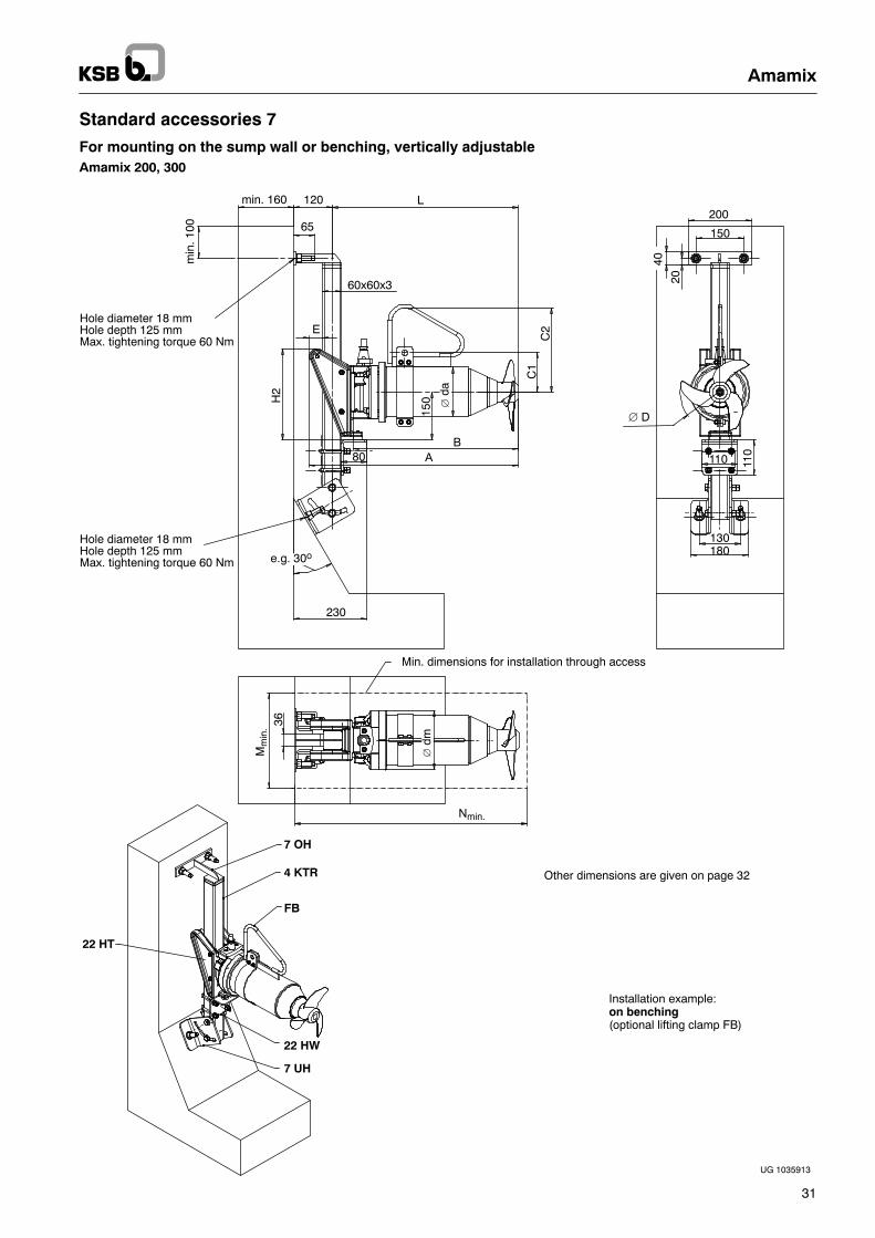
Standard accessories 7
For mounting on the sump wall or benching, vertically adjustableAmamix 200, 300
UG 1035913
Installation example:on benching(optional lifting clamp FB)
Min. dimensions for installation through access
7 OH
4 KTR
FB
22 HW
7 UH
Other dimensions are given on page 32
min. 160 120m
in.1
00 65
L
60x60x3
80 AB
150
C1
C2
230
H2
E
∅da
40
200
150
∅ D
130180
110
20
110
e.g. 30o
22 HT
Hole diameter 18 mmHole depth 125 mmMax. tightening torque 60 Nm
Hole diameter 18 mmHole depth 125 mmMax. tightening torque 60 Nm
∅dm
Mm
in.
Nmin.
36
Amamix
32
Standard accessories 7
For mounting on the sump wall or benching, vertically adjustableAmamix 200, 300
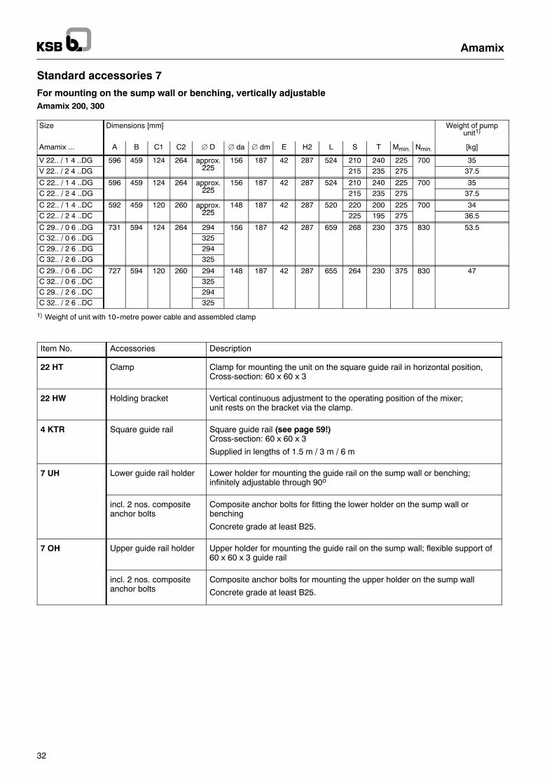
Size Dimensions [mm] Weight of pumpunit1)
Amamix ... A B C1 C2 ∅ D ∅ da ∅ dm E H2 L S T Mmin. Nmin. [kg]
V 22.. / 1 4 ..DG 596 459 124 264 approx.225
156 187 42 287 524 210 240 225 700 35V 22.. / 2 4 ..DG
pp225 215 235 275 37.5
C 22.. / 1 4 ..DG 596 459 124 264 approx.225
156 187 42 287 524 210 240 225 700 35C 22.. / 2 4 ..DG
pp225 215 235 275 37.5
C 22.. / 1 4 ..DC 592 459 120 260 approx.225
148 187 42 287 520 220 200 225 700 34C 22.. / 2 4 ..DC
pp225 225 195 275 36.5
C 29.. / 0 6 ..DG 731 594 124 264 294 156 187 42 287 659 268 230 375 830 53.5C 32.. / 0 6 ..DG 325C 29.. / 2 6 ..DG 294C 32.. / 2 6 ..DG 325
C 29.. / 0 6 ..DC 727 594 120 260 294 148 187 42 287 655 264 230 375 830 47C 32.. / 0 6 ..DC 325C 29.. / 2 6 ..DC 294C 32.. / 2 6 ..DC 325
1) Weight of unit with 10--metre power cable and assembled clamp
Item No. Accessories Description
22 HT Clamp Clamp for mounting the unit on the square guide rail in horizontal position,Cross-section: 60 x 60 x 3
22 HW Holding bracket Vertical continuous adjustment to the operating position of the mixer;unit rests on the bracket via the clamp.
4 KTR Square guide rail Square guide rail (see page 59!)Cross-section: 60 x 60 x 3
Supplied in lengths of 1.5 m / 3 m / 6 m
7 UH Lower guide rail holder Lower holder for mounting the guide rail on the sump wall or benching;infinitely adjustable through 90o
incl. 2 nos. compositeanchor bolts
Composite anchor bolts for fitting the lower holder on the sump wall orbenching
Concrete grade at least B25.
7 OH Upper guide rail holder Upper holder for mounting the guide rail on the sump wall; flexible support of60 x 60 x 3 guide rail
incl. 2 nos. compositeanchor bolts
Composite anchor bolts for mounting the upper holder on the sump wall
Concrete grade at least B25.
Amamix
33
Standard accessories 7
For mounting on the sump wall or benching, vertically adjustableAmamix 200, 300
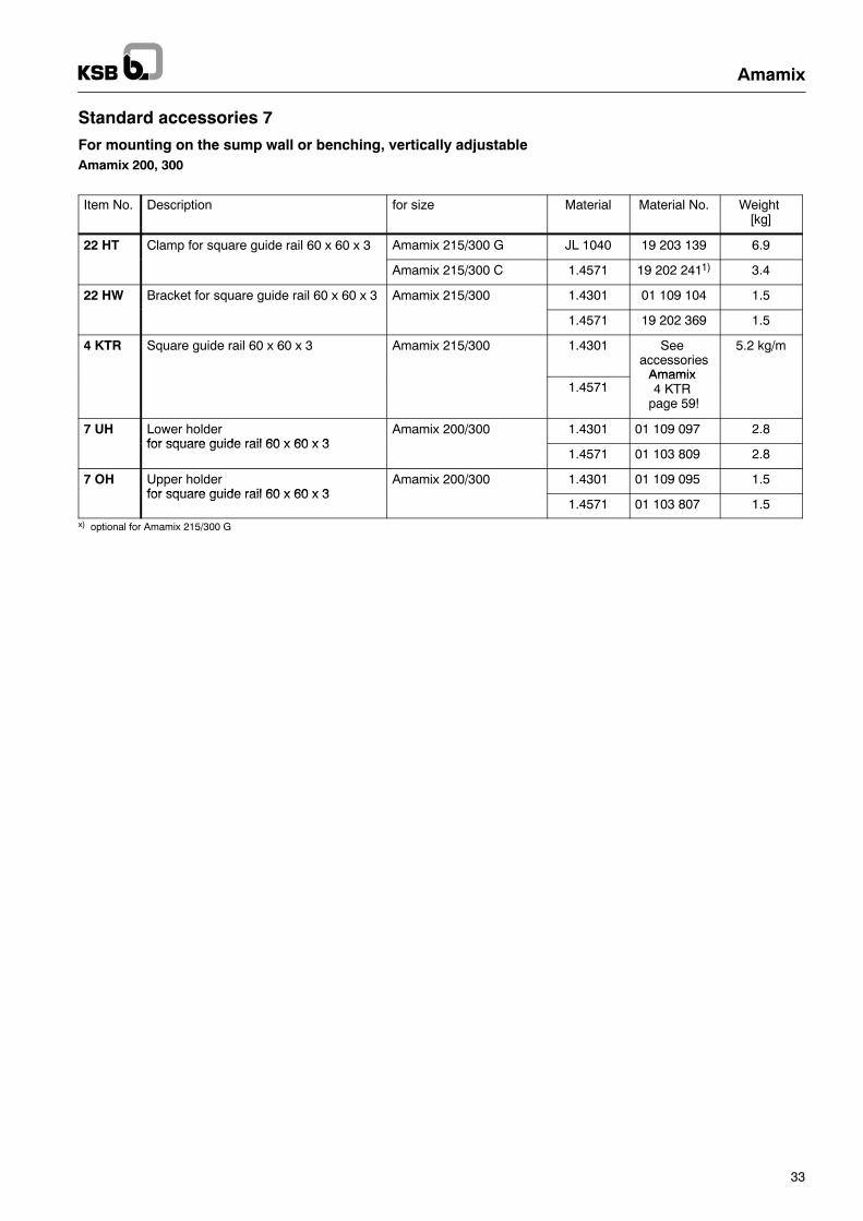
Item No. Description for size Material Material No. Weight[kg]
22 HT Clamp for square guide rail 60 x 60 x 3 Amamix 215/300 G JL 1040 19 203 139 6.9
Amamix 215/300 C 1.4571 19 202 2411) 3.4
22 HW Bracket for square guide rail 60 x 60 x 3 Amamix 215/300 1.4301 01 109 104 1.5
1.4571 19 202 369 1.5
4 KTR Square guide rail 60 x 60 x 3 Amamix 215/300 1.4301 Seeaccessories
Amamix
5.2 kg/m
1.4571Amamix4 KTR
page 59!
7 UH Lower holderfor square guide rail 60 x 60 x 3
Amamix 200/300 1.4301 01 109 097 2.8for square guide rail 60 x 60 x 3
1.4571 01 103 809 2.8
7 OH Upper holderfor square guide rail 60 x 60 x 3
Amamix 200/300 1.4301 01 109 095 1.5for square guide rail 60 x 60 x 3
1.4571 01 103 807 1.5x) optional for Amamix 215/300 G
Amamix
34
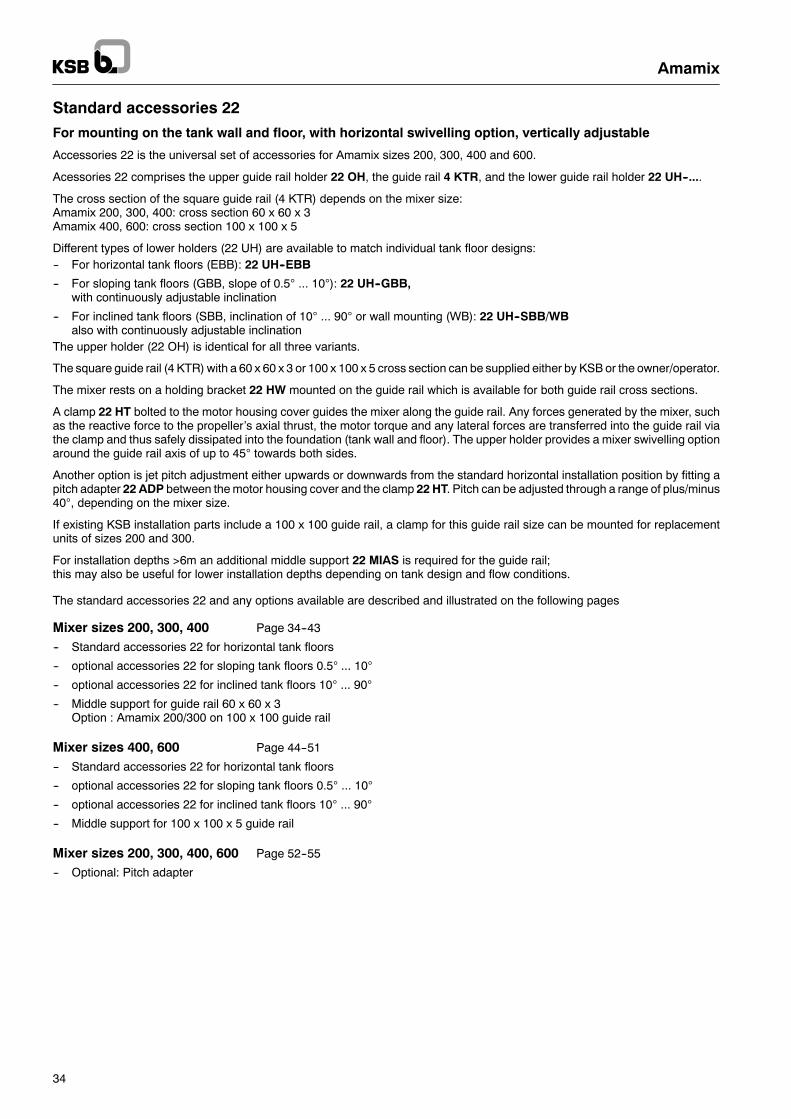
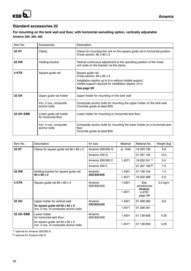
Standard accessories 22
For mounting on the tank wall and floor, with horizontal swivelling option, vertically adjustable
Accessories 22 is the universal set of accessories for Amamix sizes 200, 300, 400 and 600.
Acessories 22 comprises the upper guide rail holder 22 OH, the guide rail 4 KTR, and the lower guide rail holder 22 UH--....
The cross section of the square guide rail (4 KTR) depends on the mixer size:Amamix 200, 300, 400: cross section 60 x 60 x 3Amamix 400, 600: cross section 100 x 100 x 5
Different types of lower holders (22 UH) are available to match individual tank floor designs:-- For horizontal tank floors (EBB): 22 UH--EBB
-- For sloping tank floors (GBB, slope of 0.5° ... 10°): 22 UH--GBB,with continuously adjustable inclination
-- For inclined tank floors (SBB, inclination of 10° ... 90° or wall mounting (WB): 22 UH--SBB/WBalso with continuously adjustable inclination
The upper holder (22 OH) is identical for all three variants.
The square guide rail (4 KTR) with a 60 x 60 x 3 or 100 x 100 x 5 cross section can be supplied either by KSB or the owner/operator.
The mixer rests on a holding bracket 22 HW mounted on the guide rail which is available for both guide rail cross sections.
A clamp 22 HT bolted to the motor housing cover guides the mixer along the guide rail. Any forces generated by the mixer, suchas the reactive force to the propeller’s axial thrust, the motor torque and any lateral forces are transferred into the guide rail viathe clamp and thus safely dissipated into the foundation (tank wall and floor). The upper holder provides a mixer swivelling optionaround the guide rail axis of up to 45° towards both sides.
Another option is jet pitch adjustment either upwards or downwards from the standard horizontal installation position by fitting apitch adapter 22 ADP between the motor housing cover and the clamp 22 HT. Pitch can be adjusted through a range of plus/minus40°, depending on the mixer size.
If existing KSB installation parts include a 100 x 100 guide rail, a clamp for this guide rail size can be mounted for replacementunits of sizes 200 and 300.
For installation depths >6m an additional middle support 22 MIAS is required for the guide rail;this may also be useful for lower installation depths depending on tank design and flow conditions.
The standard accessories 22 and any options available are described and illustrated on the following pages
Mixer sizes 200, 300, 400 Page 34--43
-- Standard accessories 22 for horizontal tank floors
-- optional accessories 22 for sloping tank floors 0.5° ... 10°
-- optional accessories 22 for inclined tank floors 10° ... 90°
-- Middle support for guide rail 60 x 60 x 3Option : Amamix 200/300 on 100 x 100 guide rail
Mixer sizes 400, 600 Page 44--51
-- Standard accessories 22 for horizontal tank floors
-- optional accessories 22 for sloping tank floors 0.5° ... 10°
-- optional accessories 22 for inclined tank floors 10° ... 90°
-- Middle support for 100 x 100 x 5 guide rail
Mixer sizes 200, 300, 400, 600 Page 52--55
-- Optional: Pitch adapter
Amamix
35
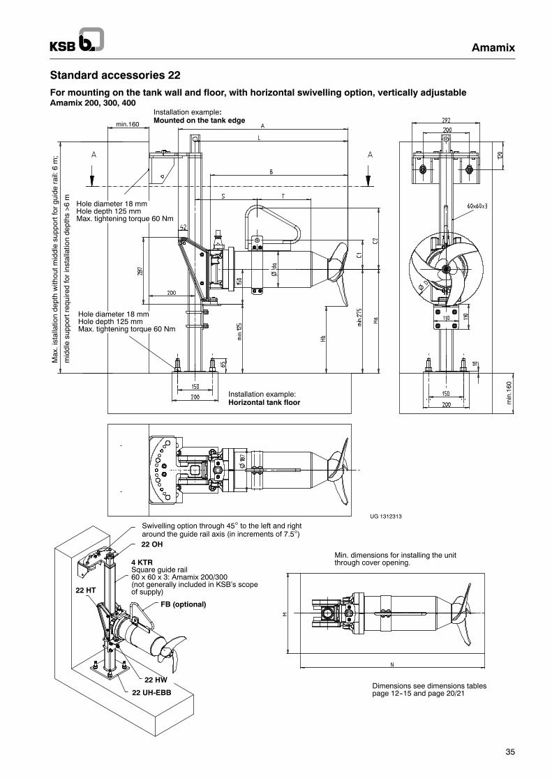
Standard accessories 22
For mounting on the tank wall and floor, with horizontal swivelling option, vertically adjustableAmamix 200, 300, 400
min
.160
min.160
Min. dimensions for installing the unitthrough cover opening.
Installation example:Horizontal tank floor
Installation example:Mounted on the tank edge
Dimensions see dimensions tablespage 12--15 and page 20/21
22 OH
22 HT
22 UH-EBB
FB (optional)
Swivelling option through 45° to the left and rightaround the guide rail axis (in increments of 7.5°)
Square guide rail60 x 60 x 3: Amamix 200/300(not generally included in KSB’s scopeof supply)
4 KTR
Hole diameter 18 mmHole depth 125 mmMax. tightening torque 60 Nm
Hole diameter 18 mmHole depth 125 mmMax. tightening torque 60 Nm
Max
.ist
alla
tion
dept
hw
ithou
tmid
dle
supp
ortf
orgu
ide
rail:
6m
;
mid
dle
supp
ortr
equi
red
for
inst
alla
tion
dept
hs>
6m
22 HW
UG 1312313
Amamix
36
Standard accessories 22
For mounting on the tank wall and floor, with horizontal swivelling option, vertically adjustableAmamix 200, 300, 400
Item No. Accessories Description
22 HT Clamp Clamp for mounting the unit on the square guide rail in horizontal position.Cross-section: 60 x 60 x 3
22 HW Holding bracket Vertical continuous adjustment to the operating position of the mixer;unit rests on the bracket via the clamp.
4 KTR Square guide rail Square guide railCross-section: 60 x 60 x 3
Installation depths up to 6 m without middle support;middle support required for installation depths >6 m
See page 59!
22 OH Upper guide rail holder Upper holder for mounting on the tank wall
Incl. 2 nos. compositeanchor bolts
Composite anchor bolts for mounting the upper holder on the tank wall.Concrete grade at least B25.
22 UH--EBB Lower guide rail holderfor horizontal floor
Lower holder for mounting on horizontal tank floor.
Incl. 4 nos. compositeanchor bolts
Composite anchor bolts for mounting the lower holder on a horizontal tankfloor.Concrete grade at least B25.
Item No. Description for size Material Material No. Weight [kg]
22 HT Clamp for square guide rail 60 x 60 x 3 Amamix 200/300 G JL 1040 19 203 139 6.9
Amamix 400 G 01 307 155 10.5
Amamix 200/300 C 1.4571 19 202 241 1) 3.4
Amamix 400 C 01 307 156 2) 7.0
22 HW Holding bracket for square guide rail60 x 60 x 3
Amamix200/300/400
1.4301 01 109 104 1.560 x 60 x 3 200/300/400
1.4571 19 202 369 3.5
4 KTR Square guide rail 60 x 60 x 3 Amamix200/300/400
1.4301 Seeaccessories
Amamix
5.2 kg/m
1.4571Amamix4 KTR
page 59!
22 OH Upper holder for vertical wall;
for square guide rail 60 x 60 x 3
Amamix200/300/400
1.4301 01 306 260 8.9for square guide rail 60 x 60 x 3incl. 2 nos. of composite anchor bolts
200/300/4001.4571 01 306 261
22 UH--EBB Lower holderfor horizontal tank floor;
Amamix200/300/400
1.4301 01 129 858 4.25
for square guide rail 60 x 60 x 3incl. 4 nos. of composite anchor bolts 1.4571 01 129 859 4.25
1) optional for Amamix 200/300 G2) optional for Amamix 400 G
Amamix
37
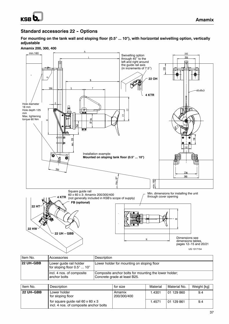
Standard accessories 22 -- Options
For mounting on the tank wall and sloping floor (0.5° ... 10°), with horizontal swivelling option, verticallyadjustableAmamix 200, 300, 400
4 KTR
FB (optional)
22 UH -- GBB
22 HT
22 HW
UG 1317154
Dimensions seedimensions tables,pages 12--15 and 20/21
Swivelling optionthrough 45° to theleft and right aroundthe guide rail axis(in increments of 7.5°)
4 KTR
22 OH
Square guide rail60 x 60 x 3: Amamix 200/300/400(not generally included in KSB’s scope of supply)
min
.160
min.160
Hole diameter18 mmHole depth 125mmMax. tighteningtorque 60 Nm
Installation example:Mounted on sloping tank floor (0.5° ... 10°)
Min. dimensions for installing the unitthrough cover opening
Item No. Accessories Description
22 UH--GBB Lower guide rail holderfor sloping floor 0.5° ... 10°
Lower holder for mounting on sloping floor
incl. 4 nos. of compositeanchor bolts
Composite anchor bolts for mounting the lower holder;Concrete grade at least B25.
Item No. Description for size Material Material No. Weight [kg]
22 UH--GBB Lower holderfor sloping floor
Amamix200/300/400
1.4301 01 129 860 9.4
for square guide rail 60 x 60 x 3incl. 4 nos. of composite anchor bolts
1.4571 01 129 861 9.4
Amamix
38
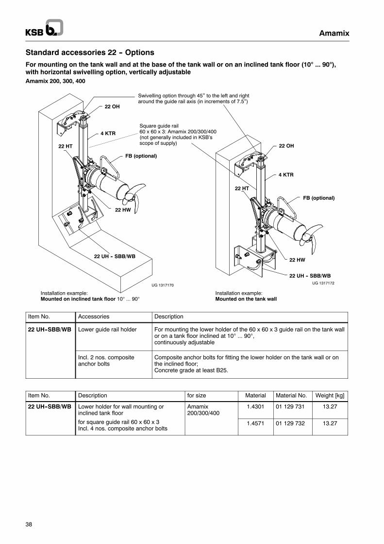
Standard accessories 22 -- Options
For mounting on the tank wall and at the base of the tank wall or on an inclined tank floor (10° ... 90°),with horizontal swivelling option, vertically adjustableAmamix 200, 300, 400
4 KTR
FB (optional)
FB (optional)
4 KTR
22 HW
22 HW
22 UH -- SBB/WB
22 UH -- SBB/WB
22 HT
22 HT
22 OH
22 OH
Square guide rail60 x 60 x 3: Amamix 200/300/400(not generally included in KSB’sscope of supply)
Installation example:Mounted on inclined tank floor 10° ... 90°
Installation example:Mounted on the tank wall
Swivelling option through 45° to the left and rightaround the guide rail axis (in increments of 7.5°)
UG 1317170 UG 1317172
Item No. Accessories Description
22 UH--SBB/WB Lower guide rail holder For mounting the lower holder of the 60 x 60 x 3 guide rail on the tank wallor on a tank floor inclined at 10° ... 90°,continuously adjustable
Incl. 2 nos. compositeanchor bolts
Composite anchor bolts for fitting the lower holder on the tank wall or onthe inclined floor;Concrete grade at least B25.
Item No. Description for size Material Material No. Weight [kg]
22 UH--SBB/WB Lower holder for wall mounting orinclined tank floor
Amamix200/300/400
1.4301 01 129 731 13.27
for square guide rail 60 x 60 x 3Incl. 4 nos. composite anchor bolts
1.4571 01 129 732 13.27
Amamix
39
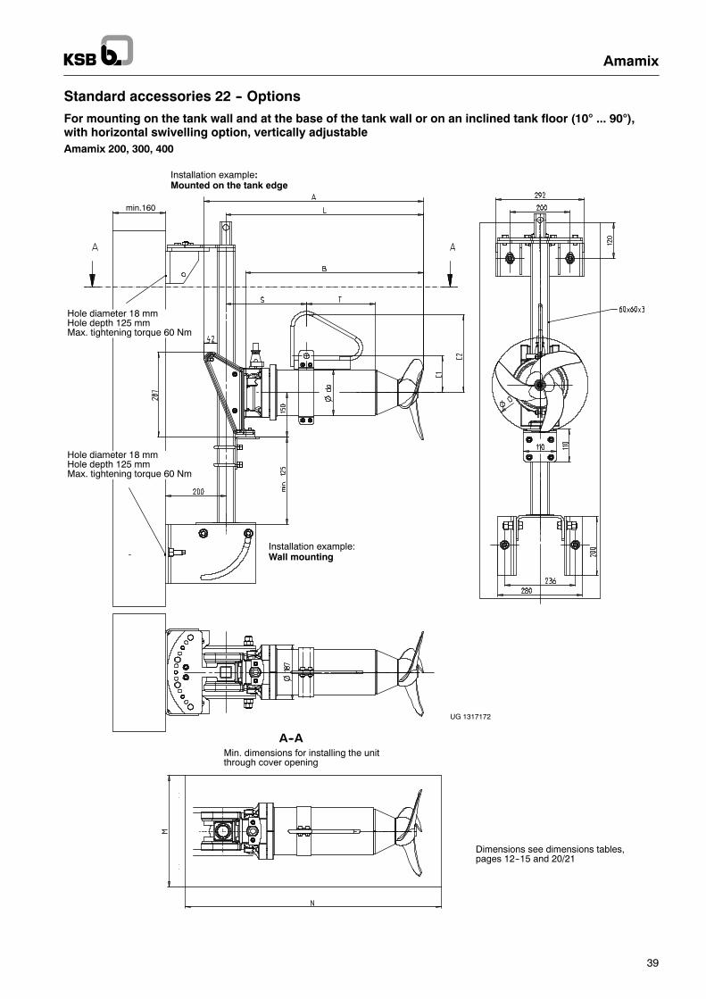
Standard accessories 22 -- Options
For mounting on the tank wall and at the base of the tank wall or on an inclined tank floor (10° ... 90°),with horizontal swivelling option, vertically adjustableAmamix 200, 300, 400
UG 1317172
min.160
Min. dimensions for installing the unitthrough cover opening
A--A
Installation example:Wall mounting
Installation example:Mounted on the tank edge
Dimensions see dimensions tables,pages 12--15 and 20/21
Hole diameter 18 mmHole depth 125 mmMax. tightening torque 60 Nm
Hole diameter 18 mmHole depth 125 mmMax. tightening torque 60 Nm
Amamix
40
Standard accessories 22 -- Options
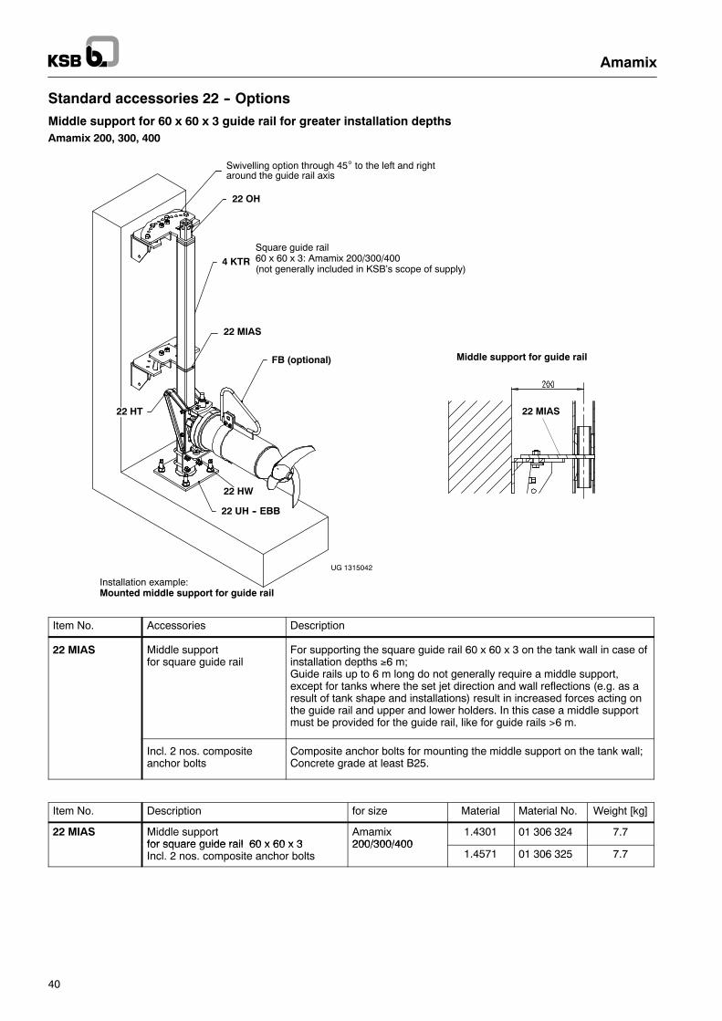
Middle support for 60 x 60 x 3 guide rail for greater installation depthsAmamix 200, 300, 400
Middle support for guide rail
4 KTR
FB (optional)
22 UH -- EBB
22 OH
Square guide rail60 x 60 x 3: Amamix 200/300/400(not generally included in KSB’s scope of supply)
22 MIAS
Installation example:Mounted middle support for guide rail
Swivelling option through 45° to the left and rightaround the guide rail axis
UG 1315042
22 MIAS
22 HW
22 HT
Item No. Accessories Description
22 MIAS Middle supportfor square guide rail
For supporting the square guide rail 60 x 60 x 3 on the tank wall in case ofinstallation depths ≥6 m;Guide rails up to 6 m long do not generally require a middle support,except for tanks where the set jet direction and wall reflections (e.g. as aresult of tank shape and installations) result in increased forces acting onthe guide rail and upper and lower holders. In this case a middle supportmust be provided for the guide rail, like for guide rails >6 m.
Incl. 2 nos. compositeanchor bolts
Composite anchor bolts for mounting the middle support on the tank wall;Concrete grade at least B25.
Item No. Description for size Material Material No. Weight [kg]
22 MIAS Middle supportfor square guide rail 60 x 60 x 3
Amamix200/300/400
1.4301 01 306 324 7.7for square guide rail 60 x 60 x 3Incl. 2 nos. composite anchor bolts
200/300/4001.4571 01 306 325 7.7
Amamix
41
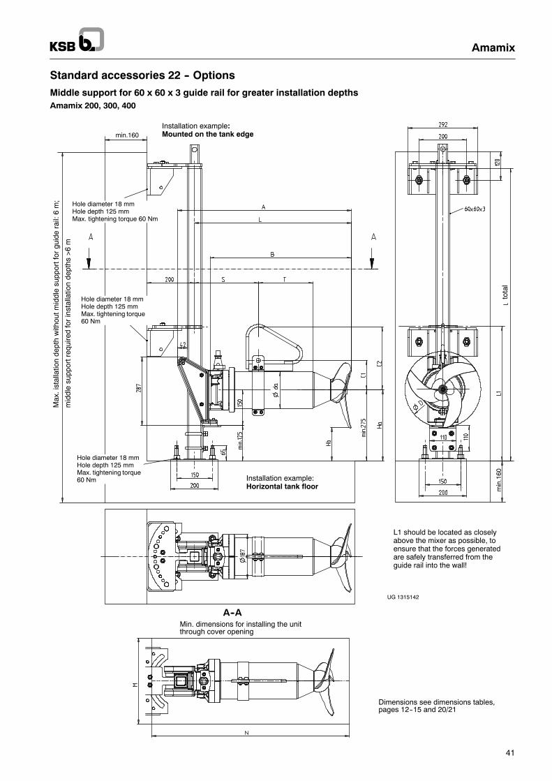
Standard accessories 22 -- Options
Middle support for 60 x 60 x 3 guide rail for greater installation depthsAmamix 200, 300, 400
UG 1315142
min.160
min
.160
tota
l
Installation example:Mounted on the tank edge
Installation example:Horizontal tank floor
Min. dimensions for installing the unitthrough cover opening
A--A
Max
.ist
alla
tion
dept
hw
ithou
tmid
dle
supp
ortf
orgu
ide
rail:
6m
;
mid
dle
supp
ortr
equi
red
for
inst
alla
tion
dept
hs>
6m
Hole diameter 18 mmHole depth 125 mmMax. tightening torque 60 Nm
Hole diameter 18 mmHole depth 125 mmMax. tightening torque60 Nm
Hole diameter 18 mmHole depth 125 mmMax. tightening torque60 Nm
Dimensions see dimensions tables,pages 12--15 and 20/21
L1 should be located as closelyabove the mixer as possible, toensure that the forces generatedare safely transferred from theguide rail into the wall!
Amamix
42
Standard accessories 22 -- Options
Amamix 200 and 300 with clamp for guide rail 100 x 100
The standard version of Amamix 200/300 with accessories set no. 22 is designed for the (square) guide rail measuring60 x 60 x 3 (new installations).
If a square guide rail 100 x 100 has been specified, or if a square guide rail 100 x 100 is already installed (e.g. in the case of KSBreplacement units), Amamix 200/300 units can be retrofitted with the following clamps instead of the standard clamps:
-- Amamix 200/300 material variant G -- Clamp 19 556 701 (JL 1040)/optional clamp 19202242 (1.4571)
-- Amamix 200/300 material variant C -- Clamp 19 202 242 (1.4571)
The clamp is already provided with the holes required for fastening the Amamix 200/300 unit.Mounting to the motor housing cover: 4 cheese--head screws M8; tightening torque 17 Nm.
Compared to the technical data given in the type series booklet for the standard version (clamp for square guide rail 60 x 60 x 3)(dimensions sheet), the complete unit weight, incl. clamp and 10--metre power cable, will be increased by 9.1 kg (”G” variant) or5.1 kg (”C” variant).
This higher--weight clamp also results in different dimensions and a different position of the supporting clamp, as shown on thenext page.
Please note:Holding brackets already mounted on the guide rail (for adjusting the unit’s distance from the floor) do not need to be replaced.Once the unit is lowered, it will rest on these brackets via the flexible rubber buffers mounted on the clamp.
Amamix
43
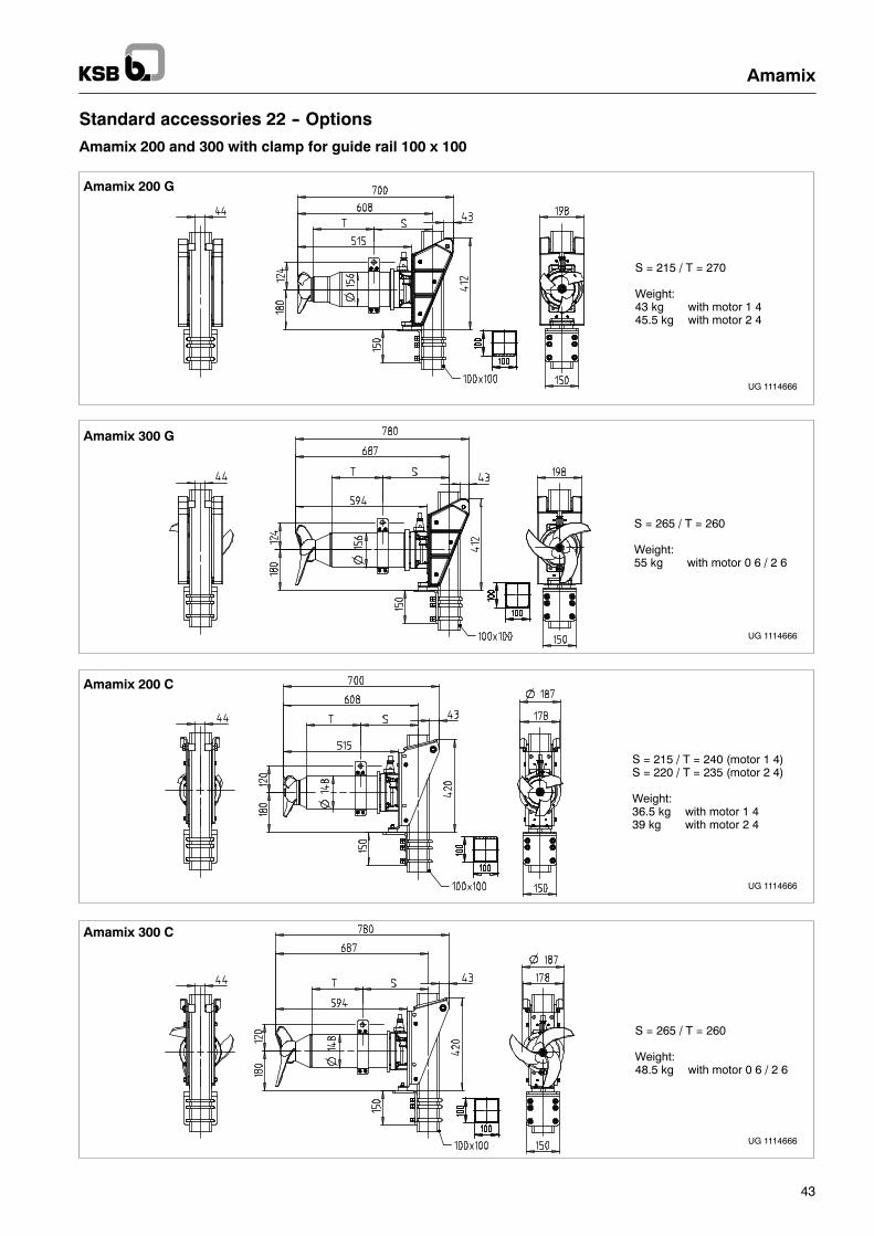
Standard accessories 22 -- Options
Amamix 200 and 300 with clamp for guide rail 100 x 100
S = 215 / T = 270
Weight:43 kg with motor 1 445.5 kg with motor 2 4
Amamix 200 G
UG 1114666
S = 265 / T = 260
Weight:55 kg with motor 0 6 / 2 6
Amamix 300 G
UG 1114666
Amamix 200 C
S = 215 / T = 240 (motor 1 4)S = 220 / T = 235 (motor 2 4)
Weight:36.5 kg with motor 1 439 kg with motor 2 4
UG 1114666
Amamix 300 C
S = 265 / T = 260
Weight:48.5 kg with motor 0 6 / 2 6
UG 1114666
Amamix
44
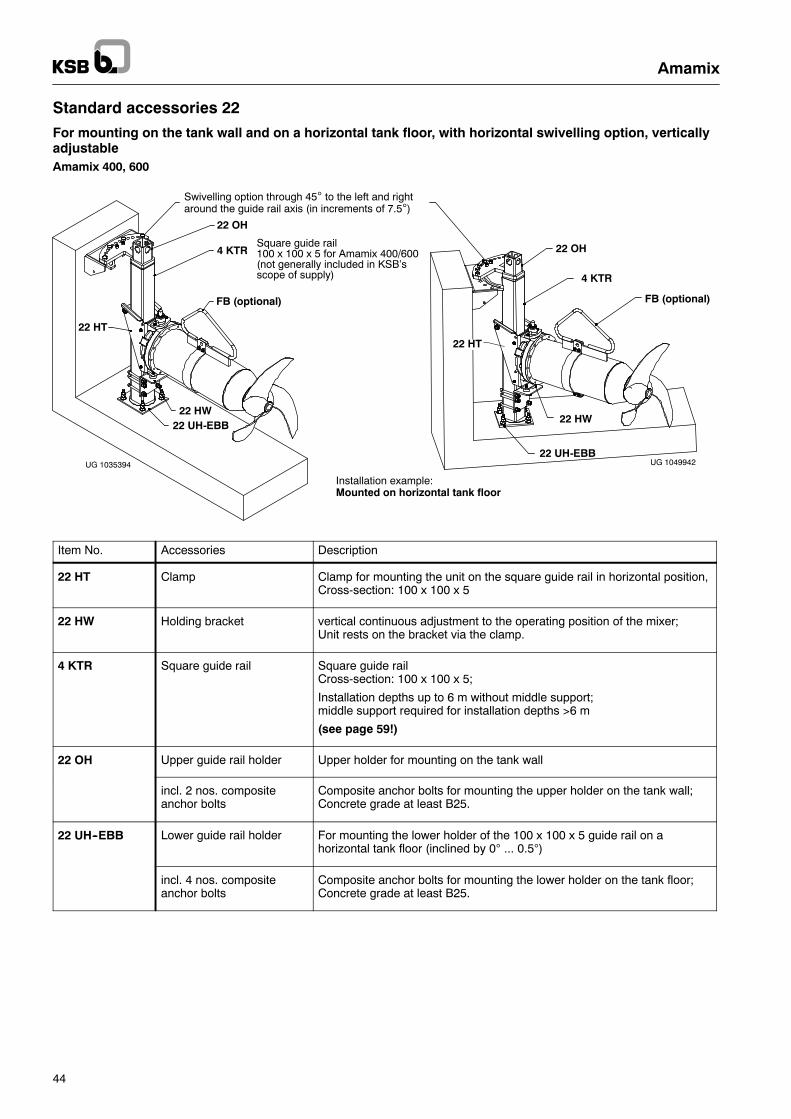
Standard accessories 22
For mounting on the tank wall and on a horizontal tank floor, with horizontal swivelling option, verticallyadjustableAmamix 400, 600
Installation example:Mounted on horizontal tank floor
22 OH
4 KTR
22 HW
22 HT
22 UH-EBB
FB (optional)
Square guide rail100 x 100 x 5 for Amamix 400/600(not generally included in KSB’sscope of supply)
UG 1035394 UG 1049942
22 OH
4 KTR
22 HW
22 HT
22 UH-EBB
FB (optional)
Swivelling option through 45° to the left and rightaround the guide rail axis (in increments of 7.5°)
Item No. Accessories Description
22 HT Clamp Clamp for mounting the unit on the square guide rail in horizontal position,Cross-section: 100 x 100 x 5
22 HW Holding bracket vertical continuous adjustment to the operating position of the mixer;Unit rests on the bracket via the clamp.
4 KTR Square guide rail Square guide railCross-section: 100 x 100 x 5;
Installation depths up to 6 m without middle support;middle support required for installation depths >6 m
(see page 59!)
22 OH Upper guide rail holder Upper holder for mounting on the tank wall
incl. 2 nos. compositeanchor bolts
Composite anchor bolts for mounting the upper holder on the tank wall;Concrete grade at least B25.
22 UH--EBB Lower guide rail holder For mounting the lower holder of the 100 x 100 x 5 guide rail on ahorizontal tank floor (inclined by 0° ... 0.5°)
incl. 4 nos. compositeanchor bolts
Composite anchor bolts for mounting the lower holder on the tank floor;Concrete grade at least B25.
Amamix
45
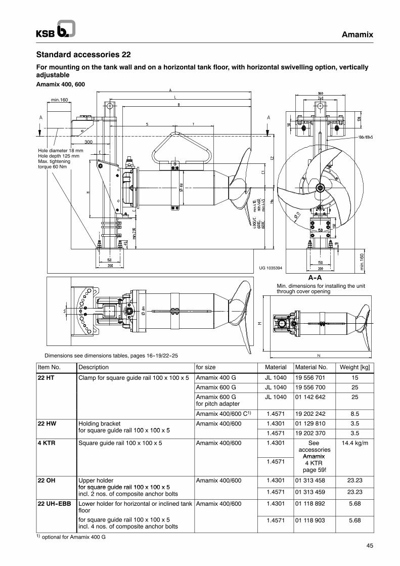
Standard accessories 22
For mounting on the tank wall and on a horizontal tank floor, with horizontal swivelling option, verticallyadjustableAmamix 400, 600
UG 1035394
Min. dimensions for installing the unitthrough cover opening
A--A
Dimensions see dimensions tables, pages 16--19/22--25
Hole diameter 18 mmHole depth 125 mmMax. tighteningtorque 60 Nm
min.160
min
.160
300
Item No. Description for size Material Material No. Weight [kg]
22 HT Clamp for square guide rail 100 x 100 x 5 Amamix 400 G JL 1040 19 556 701 15p q g
Amamix 600 G JL 1040 19 556 700 25
Amamix 600 Gfor pitch adapter
JL 1040 01 142 642 25
Amamix 400/600 C1) 1.4571 19 202 242 8.5
22 HW Holding bracketf id il 100 100 5
Amamix 400/600 1.4301 01 129 810 3.5gfor square guide rail 100 x 100 x 5 1.4571 19 202 370 3.5
4 KTR Square guide rail 100 x 100 x 5 Amamix 400/600 1.4301 Seeaccessories
Amamix
14.4 kg/m
1.4571Amamix4 KTR
page 59!
22 OH Upper holderfor square guide rail 100 x 100 x 5
Amamix 400/600 1.4301 01 313 458 23.23for square guide rail 100 x 100 x 5incl. 2 nos. of composite anchor bolts 1.4571 01 313 459 23.23
22 UH--EBB Lower holder for horizontal or inclined tankfloor
Amamix 400/600 1.4301 01 118 892 5.68
for square guide rail 100 x 100 x 5incl. 4 nos. of composite anchor bolts
1.4571 01 118 903 5.68
1) optional for Amamix 400 G
Amamix
46
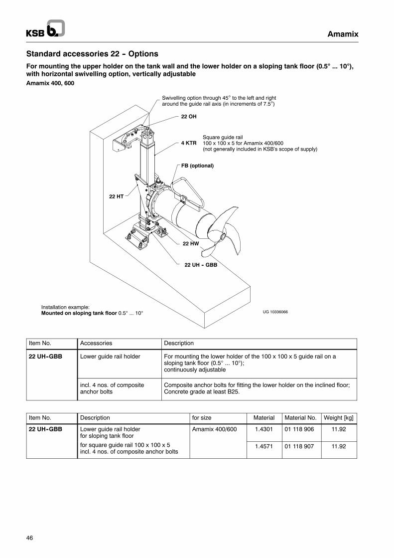
Standard accessories 22 -- Options
For mounting the upper holder on the tank wall and the lower holder on a sloping tank floor (0.5° ... 10°),with horizontal swivelling option, vertically adjustableAmamix 400, 600
4 KTR
FB (optional)
22 UH -- GBB
22 HT
Installation example:Mounted on sloping tank floor 0.5° ... 10°
22 HW
22 OH
Square guide rail100 x 100 x 5 for Amamix 400/600(not generally included in KSB’s scope of supply)
UG 10336066
Swivelling option through 45° to the left and rightaround the guide rail axis (in increments of 7.5°)
Item No. Accessories Description
22 UH--GBB Lower guide rail holder For mounting the lower holder of the 100 x 100 x 5 guide rail on asloping tank floor (0.5° ... 10°);continuously adjustable
incl. 4 nos. of compositeanchor bolts
Composite anchor bolts for fitting the lower holder on the inclined floor;Concrete grade at least B25.
Item No. Description for size Material Material No. Weight [kg]
22 UH--GBB Lower guide rail holderfor sloping tank floor
Amamix 400/600 1.4301 01 118 906 11.92
for square guide rail 100 x 100 x 5incl. 4 nos. of composite anchor bolts
1.4571 01 118 907 11.92
Amamix
47
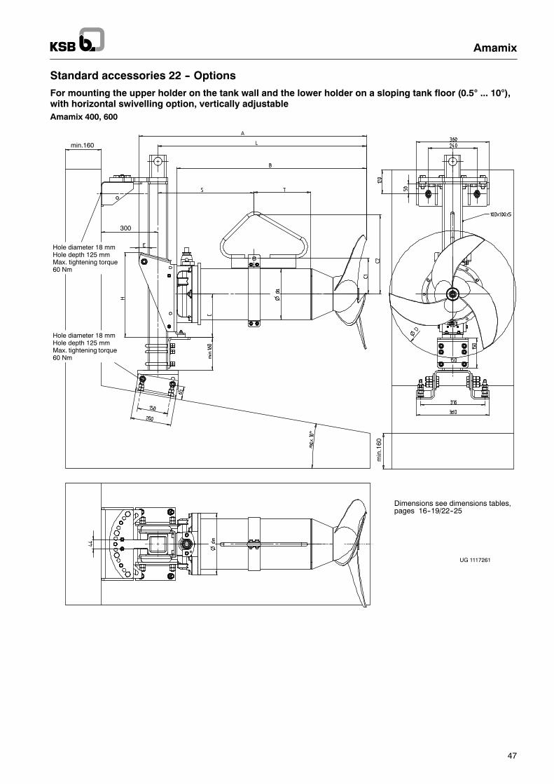
Standard accessories 22 -- Options
For mounting the upper holder on the tank wall and the lower holder on a sloping tank floor (0.5° ... 10°),with horizontal swivelling option, vertically adjustableAmamix 400, 600
UG 1117261
Hole diameter 18 mmHole depth 125 mmMax. tightening torque60 Nm
Dimensions see dimensions tables,pages 16--19/22--25
Hole diameter 18 mmHole depth 125 mmMax. tightening torque60 Nm
min
.160
min.160
300
Amamix
48
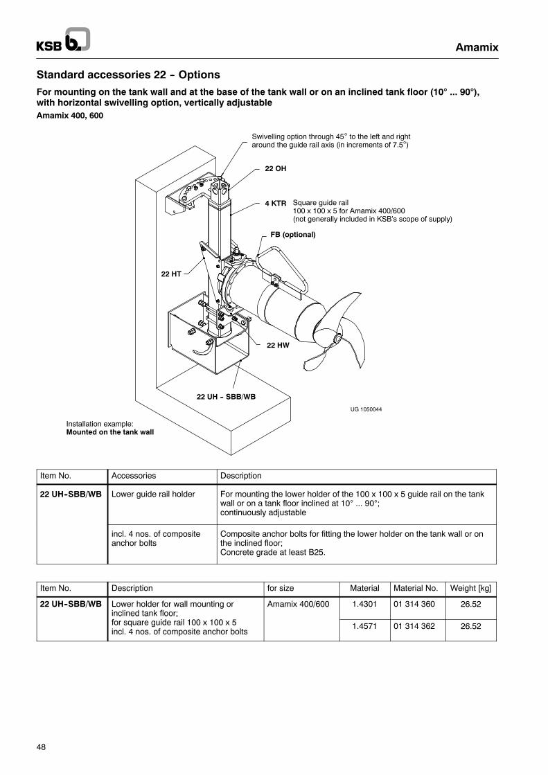
Standard accessories 22 -- Options
For mounting on the tank wall and at the base of the tank wall or on an inclined tank floor (10° ... 90°),with horizontal swivelling option, vertically adjustableAmamix 400, 600
Square guide rail100 x 100 x 5 for Amamix 400/600(not generally included in KSB’s scope of supply)
FB (optional)
4 KTR
22 HW
22 UH -- SBB/WB
22 HT
22 OH
Installation example:Mounted on the tank wall
UG 1050044
Swivelling option through 45° to the left and rightaround the guide rail axis (in increments of 7.5°)
Item No. Accessories Description
22 UH--SBB/WB Lower guide rail holder For mounting the lower holder of the 100 x 100 x 5 guide rail on the tankwall or on a tank floor inclined at 10° ... 90°;continuously adjustable
incl. 4 nos. of compositeanchor bolts
Composite anchor bolts for fitting the lower holder on the tank wall or onthe inclined floor;Concrete grade at least B25.
Item No. Description for size Material Material No. Weight [kg]
22 UH--SBB/WB Lower holder for wall mounting orinclined tank floor;f
Amamix 400/600 1.4301 01 314 360 26.52c ed a oo ;
for square guide rail 100 x 100 x 5incl. 4 nos. of composite anchor bolts
1.4571 01 314 362 26.52
Amamix
49
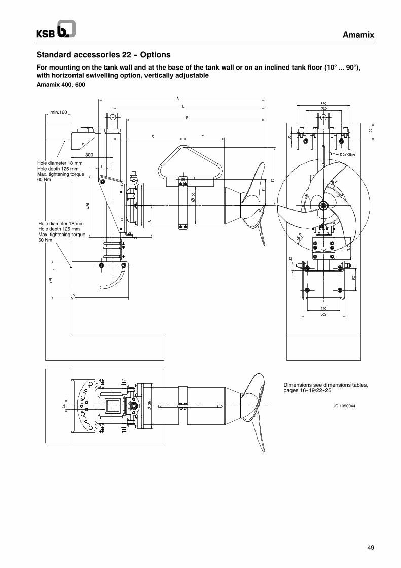
Standard accessories 22 -- Options
For mounting on the tank wall and at the base of the tank wall or on an inclined tank floor (10° ... 90°),with horizontal swivelling option, vertically adjustableAmamix 400, 600
UG 1050044
Dimensions see dimensions tables,pages 16--19/22--25
Hole diameter 18 mmHole depth 125 mmMax. tightening torque60 Nm
Hole diameter 18 mmHole depth 125 mmMax. tightening torque60 Nm
min.160
300
Amamix
50
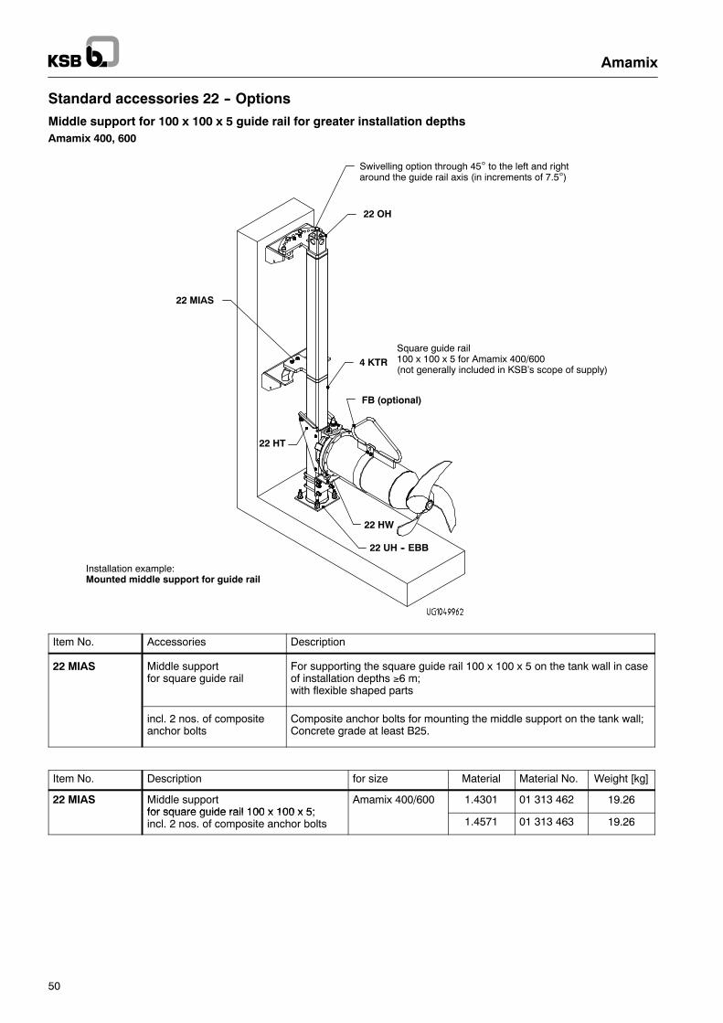
Standard accessories 22 -- Options
Middle support for 100 x 100 x 5 guide rail for greater installation depthsAmamix 400, 600
Installation example:Mounted middle support for guide rail
4 KTR
FB (optional)
22 HW
22 UH -- EBB
22 HT
22 OH
Square guide rail100 x 100 x 5 for Amamix 400/600(not generally included in KSB’s scope of supply)
22 MIAS
Swivelling option through 45° to the left and rightaround the guide rail axis (in increments of 7.5°)
Item No. Accessories Description
22 MIAS Middle supportfor square guide rail
For supporting the square guide rail 100 x 100 x 5 on the tank wall in caseof installation depths ≥6 m;with flexible shaped parts
incl. 2 nos. of compositeanchor bolts
Composite anchor bolts for mounting the middle support on the tank wall;Concrete grade at least B25.
Item No. Description for size Material Material No. Weight [kg]
22 MIAS Middle supportfor square guide rail 100 x 100 x 5;
Amamix 400/600 1.4301 01 313 462 19.26for square guide rail 100 x 100 x 5;incl. 2 nos. of composite anchor bolts 1.4571 01 313 463 19.26
Amamix
51
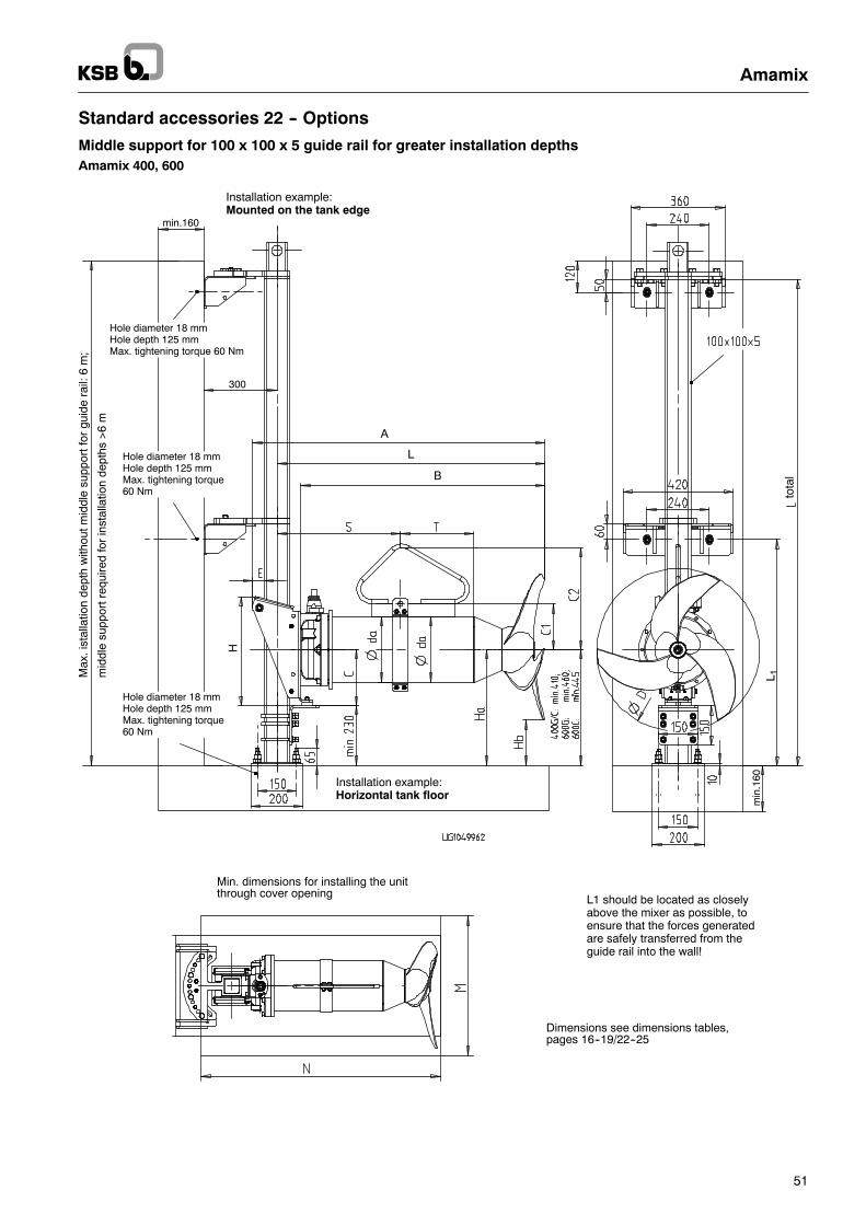
Standard accessories 22 -- Options
Middle support for 100 x 100 x 5 guide rail for greater installation depthsAmamix 400, 600
Min. dimensions for installing the unitthrough cover opening L1 should be located as closely
above the mixer as possible, toensure that the forces generatedare safely transferred from theguide rail into the wall!
Dimensions see dimensions tables,pages 16--19/22--25
Hole diameter 18 mmHole depth 125 mmMax. tightening torque60 Nm
Hole diameter 18 mmHole depth 125 mmMax. tightening torque 60 Nm
Hole diameter 18 mmHole depth 125 mmMax. tightening torque60 Nm
Installation example:Horizontal tank floor
Installation example:Mounted on the tank edge
H
A
L
B
L 1Max
.ist
alla
tion
dept
hw
ithou
tmid
dle
supp
ortf
orgu
ide
rail:
6m
;
mid
dle
supp
ortr
equi
red
for
inst
alla
tion
dept
hs>
6m
tota
l
min.160
min
.160
300
Amamix
52
Accessories 22 -- Options
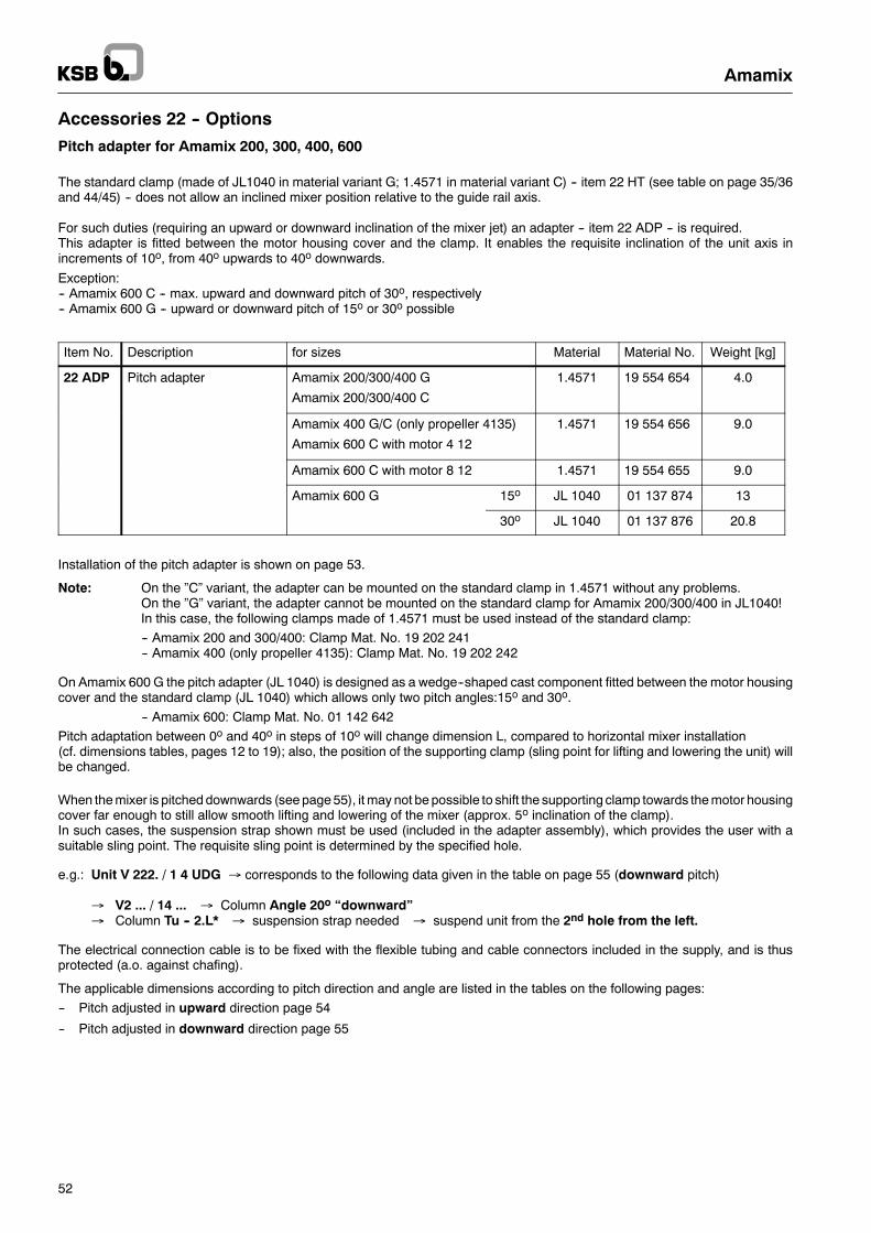
Pitch adapter for Amamix 200, 300, 400, 600
The standard clamp (made of JL1040 in material variant G; 1.4571 in material variant C) -- item 22 HT (see table on page 35/36and 44/45) -- does not allow an inclined mixer position relative to the guide rail axis.
For such duties (requiring an upward or downward inclination of the mixer jet) an adapter -- item 22 ADP -- is required.This adapter is fitted between the motor housing cover and the clamp. It enables the requisite inclination of the unit axis inincrements of 10o, from 40o upwards to 40o downwards.
Exception:-- Amamix 600 C -- max. upward and downward pitch of 30o, respectively-- Amamix 600 G -- upward or downward pitch of 15o or 30o possible
Item No. Description for sizes Material Material No. Weight [kg]
22 ADP Pitch adapter Amamix 200/300/400 G
Amamix 200/300/400 C
1.4571 19 554 654 4.0
Amamix 400 G/C (only propeller 4135)
Amamix 600 C with motor 4 12
1.4571 19 554 656 9.0
Amamix 600 C with motor 8 12 1.4571 19 554 655 9.0
Amamix 600 G 15o JL 1040 01 137 874 13
30o JL 1040 01 137 876 20.8
Installation of the pitch adapter is shown on page 53.
Note: On the ”C” variant, the adapter can be mounted on the standard clamp in 1.4571 without any problems.On the ”G” variant, the adapter cannot be mounted on the standard clamp for Amamix 200/300/400 in JL1040!In this case, the following clamps made of 1.4571 must be used instead of the standard clamp:
-- Amamix 200 and 300/400: Clamp Mat. No. 19 202 241-- Amamix 400 (only propeller 4135): Clamp Mat. No. 19 202 242
On Amamix 600 G the pitch adapter (JL 1040) is designed as a wedge--shaped cast component fitted between the motor housingcover and the standard clamp (JL 1040) which allows only two pitch angles:15o and 30o.
-- Amamix 600: Clamp Mat. No. 01 142 642
Pitch adaptation between 0o and 40o in steps of 10o will change dimension L, compared to horizontal mixer installation(cf. dimensions tables, pages 12 to 19); also, the position of the supporting clamp (sling point for lifting and lowering the unit) willbe changed.
When the mixer is pitched downwards (see page 55), it may not be possible to shift the supporting clamp towards the motor housingcover far enough to still allow smooth lifting and lowering of the mixer (approx. 5o inclination of the clamp).In such cases, the suspension strap shown must be used (included in the adapter assembly), which provides the user with asuitable sling point. The requisite sling point is determined by the specified hole.
e.g.: Unit V 222. / 1 4 UDG → corresponds to the following data given in the table on page 55 (downward pitch)
→ V2 ... / 14 ... → Column Angle 20o “downward”→ Column Tu -- 2.L* → suspension strap needed → suspend unit from the 2nd hole from the left.
The electrical connection cable is to be fixed with the flexible tubing and cable connectors included in the supply, and is thusprotected (a.o. against chafing).
The applicable dimensions according to pitch direction and angle are listed in the tables on the following pages:
-- Pitch adjusted in upward direction page 54
-- Pitch adjusted in downward direction page 55
Amamix
53
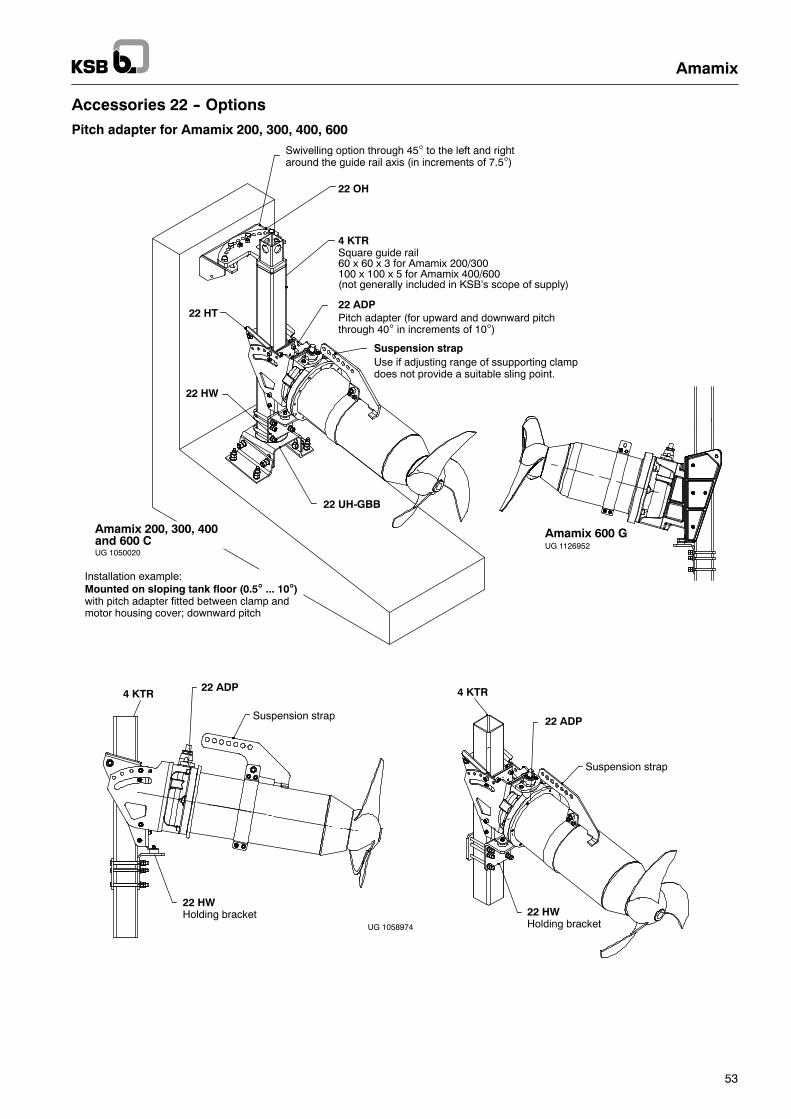
Accessories 22 -- Options
Pitch adapter for Amamix 200, 300, 400, 600
UG 1058974
Suspension strap
22 HWHolding bracket
4 KTR
Pitch adapter (for upward and downward pitchthrough 40° in increments of 10°)
Suspension strap
22 ADP
4 KTRSquare guide rail60 x 60 x 3 for Amamix 200/300100 x 100 x 5 for Amamix 400/600(not generally included in KSB’s scope of supply)
22 OH
22 UH-GBB
22 HT
22 HW
Use if adjusting range of ssupporting clampdoes not provide a suitable sling point.
Suspension strap
4 KTR
22 HWHolding bracket
22 ADP
22 ADP
Installation example:Mounted on sloping tank floor (0.5° ... 10°)with pitch adapter fitted between clamp andmotor housing cover; downward pitch
UG 1050020
Amamix 200, 300, 400and 600 C UG 1126952
Amamix 600 G
Swivelling option through 45° to the left and rightaround the guide rail axis (in increments of 7.5°)
Amamix
54
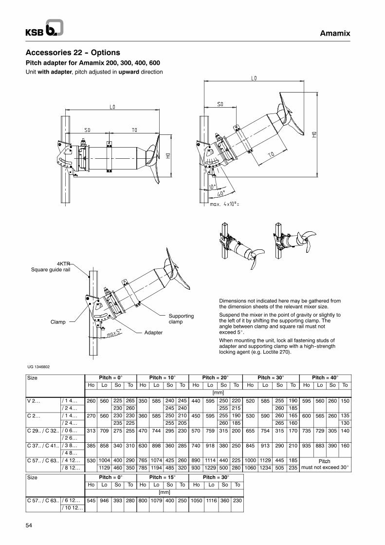
Accessories 22 -- OptionsPitch adapter for Amamix 200, 300, 400, 600Unit with adapter, pitch adjusted in upward direction
SupportingclampClamp
Adapter
4KTRSquare guide rail
Dimensions not indicated here may be gathered fromthe dimension sheets of the relevant mixer size.
Suspend the mixer in the point of gravity or slightly tothe left of it by shifting the supporting clamp. Theangle between clamp and square rail must notexceed 5_.
When mounting the unit, lock all fastening studs ofadapter and supporting clamp with a high--strengthlocking agent (e.g. Loctite 270).
UG 1346802
Size Pitch = 0° Pitch = 10° Pitch = 20° Pitch = 30° Pitch = 40°Ho Lo So To Ho Lo So To Ho Lo So To Ho Lo So To Ho Lo So To
[mm]
V 2… / 1 4… 260 560 225 265 350 585 240 245 440 595 250 220 520 585 255 190 595 560 260 150/ 2 4… 230 260 245 240 255 215 260 185
C 2… / 1 4… 270 560 230 230 360 585 250 210 450 595 255 190 530 590 260 165 600 565 260 135/ 2 4… 235 225 255 205 260 185 265 160 130
C 29.. / C 32.. / 0 6… 313 709 275 255 470 744 295 230 570 759 315 200 655 754 315 170 735 729 305 140// 2 6…
C 37.. / C 41.. / 3 8… 385 858 340 310 630 898 360 285 740 918 380 250 845 913 290 210 935 883 390 160// 4 8…
C 57.. / C 63.. / 4 12… 530 1004 400 290 765 1074 425 260 890 1114 440 225 1000 1129 445 185 Pitch// 8 12… 1129 460 350 785 1194 485 320 930 1229 500 280 1060 1234 505 235
Pitchmust not exceed 30_
Size Pitch = 0° Pitch = 15° Pitch = 30°Ho Lo So To Ho Lo So To Ho Lo So To
[mm]
C 57.. / C 63.. / 6 12… 545 946 393 280 800 1079 400 250 1050 1116 360 230// 10 12…
Amamix
55
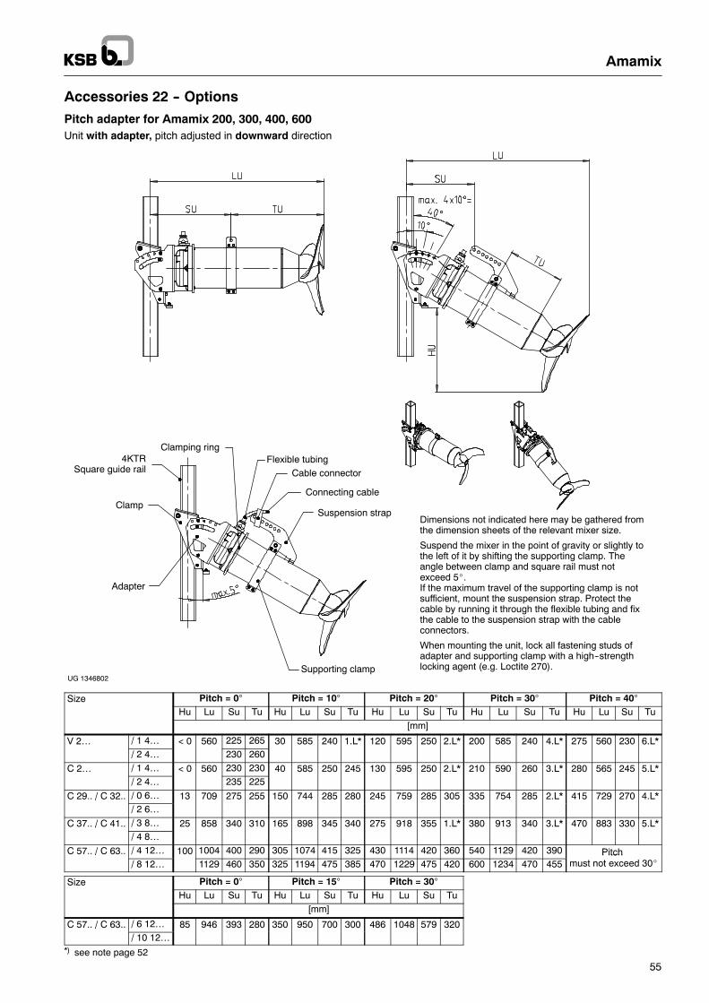
Accessories 22 -- Options
Pitch adapter for Amamix 200, 300, 400, 600Unit with adapter, pitch adjusted in downward direction
Supporting clamp
Adapter
Dimensions not indicated here may be gathered fromthe dimension sheets of the relevant mixer size.
Suspend the mixer in the point of gravity or slightly tothe left of it by shifting the supporting clamp. Theangle between clamp and square rail must notexceed 5_.If the maximum travel of the supporting clamp is notsufficient, mount the suspension strap. Protect thecable by running it through the flexible tubing and fixthe cable to the suspension strap with the cableconnectors.
When mounting the unit, lock all fastening studs ofadapter and supporting clamp with a high--strengthlocking agent (e.g. Loctite 270).
4KTRSquare guide rail
Clamp
Clamping ring
Cable connectorFlexible tubing
Connecting cable
Suspension strap
UG 1346802
Size Pitch = 0° Pitch = 10° Pitch = 20° Pitch = 30° Pitch = 40°Hu Lu Su Tu Hu Lu Su Tu Hu Lu Su Tu Hu Lu Su Tu Hu Lu Su Tu
[mm]
V 2… / 1 4… < 0 560 225 265 30 585 240 1.L* 120 595 250 2.L* 200 585 240 4.L* 275 560 230 6.L*/ 2 4… 230 260
C 2… / 1 4… < 0 560 230 230 40 585 250 245 130 595 250 2.L* 210 590 260 3.L* 280 565 245 5.L*/ 2 4… 235 225
C 29.. / C 32.. / 0 6… 13 709 275 255 150 744 285 280 245 759 285 305 335 754 285 2.L* 415 729 270 4.L*// 2 6…
C 37.. / C 41.. / 3 8… 25 858 340 310 165 898 345 340 275 918 355 1.L* 380 913 340 3.L* 470 883 330 5.L*// 4 8…
C 57.. / C 63.. / 4 12… 100 1004 400 290 305 1074 415 325 430 1114 420 360 540 1129 420 390 Pitch// 8 12… 1129 460 350 325 1194 475 385 470 1229 475 420 600 1234 470 455
Pitchmust not exceed 30_
Size Pitch = 0° Pitch = 15° Pitch = 30°Hu Lu Su Tu Hu Lu Su Tu Hu Lu Su Tu
[mm]
C 57.. / C 63.. / 6 12… 85 946 393 280 350 950 700 300 486 1048 579 320// 10 12…
*) see note page 52
Amamix
56
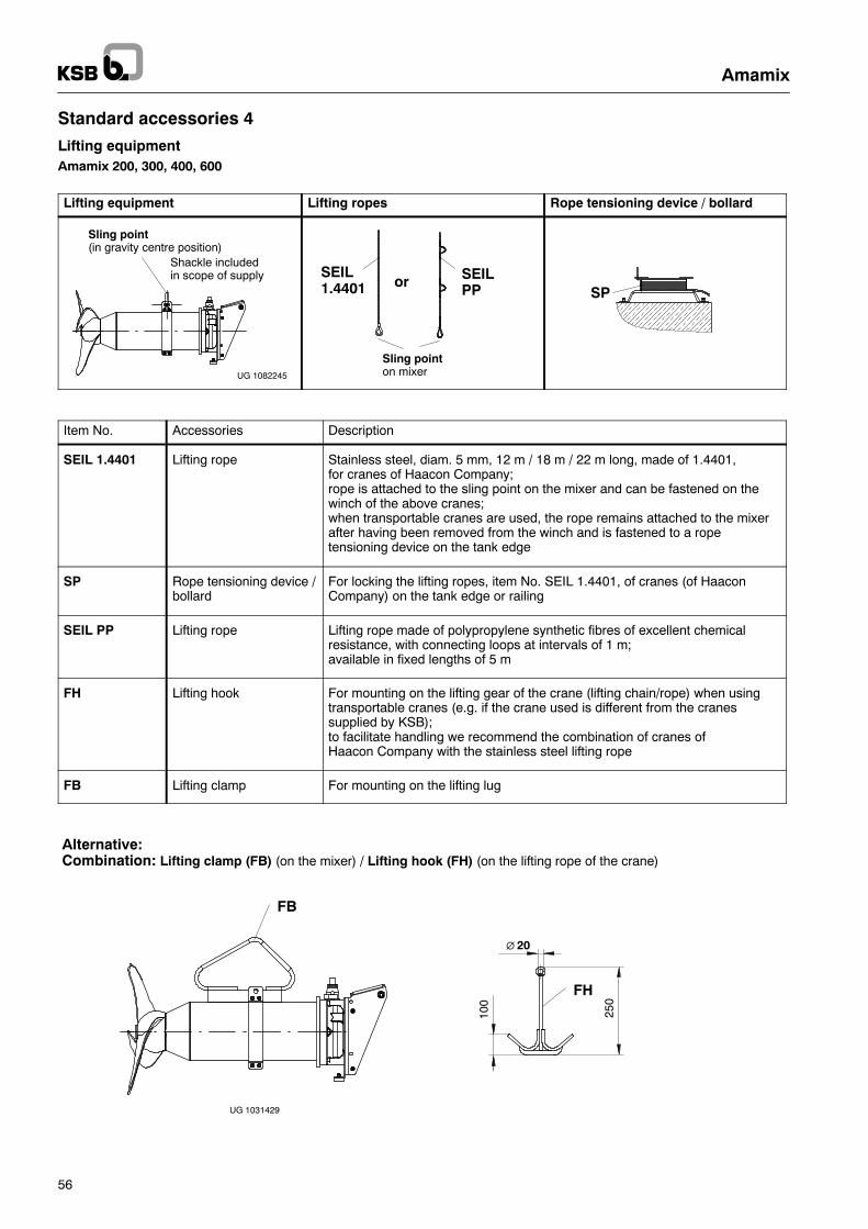
Standard accessories 4
Lifting equipmentAmamix 200, 300, 400, 600
Lifting equipment Lifting ropes Rope tensioning device / bollard
UG 1082245
Sling point(in gravity centre position)
Shackle includedin scope of supply SEIL
PPSEIL1.4401 or
Sling pointon mixer
SP
Item No. Accessories Description
SEIL 1.4401 Lifting rope Stainless steel, diam. 5 mm, 12 m / 18 m / 22 m long, made of 1.4401,for cranes of Haacon Company;rope is attached to the sling point on the mixer and can be fastened on thewinch of the above cranes;when transportable cranes are used, the rope remains attached to the mixerafter having been removed from the winch and is fastened to a ropetensioning device on the tank edge
SP Rope tensioning device /bollard
For locking the lifting ropes, item No. SEIL 1.4401, of cranes (of HaaconCompany) on the tank edge or railing
SEIL PP Lifting rope Lifting rope made of polypropylene synthetic fibres of excellent chemicalresistance, with connecting loops at intervals of 1 m;available in fixed lengths of 5 m
FH Lifting hook For mounting on the lifting gear of the crane (lifting chain/rope) when usingtransportable cranes (e.g. if the crane used is different from the cranessupplied by KSB);to facilitate handling we recommend the combination of cranes ofHaacon Company with the stainless steel lifting rope
FB Lifting clamp For mounting on the lifting lug
FH
Alternative:Combination: Lifting clamp (FB) (on the mixer) / Lifting hook (FH) (on the lifting rope of the crane)
250
100
∅ 20
FB
UG 1031429
Amamix
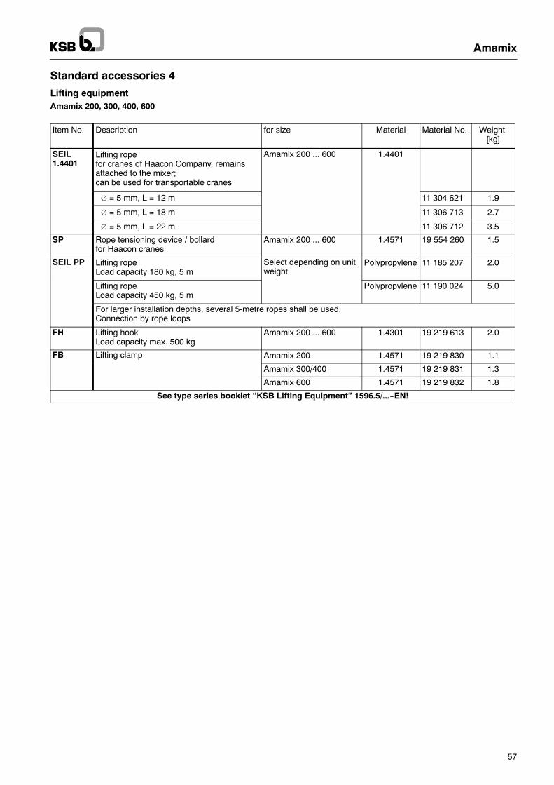
57
Standard accessories 4
Lifting equipmentAmamix 200, 300, 400, 600
Item No. Description for size Material Material No. Weight[kg]
SEIL1.4401
Lifting ropefor cranes of Haacon Company, remainsattached to the mixer;can be used for transportable cranes
Amamix 200 ... 600 1.4401
∅ = 5 mm, L = 12 m 11 304 621 1.9
∅ = 5 mm, L = 18 m 11 306 713 2.7
∅ = 5 mm, L = 22 m 11 306 712 3.5
SP Rope tensioning device / bollardfor Haacon cranes
Amamix 200 ... 600 1.4571 19 554 260 1.5
SEIL PP Lifting ropeLoad capacity 180 kg, 5 m
Select depending on unitweight
Polypropylene 11 185 207 2.0
Lifting ropeLoad capacity 450 kg, 5 m
Polypropylene 11 190 024 5.0
For larger installation depths, several 5-metre ropes shall be used.Connection by rope loops
FH Lifting hookLoad capacity max. 500 kg
Amamix 200 ... 600 1.4301 19 219 613 2.0
FB Lifting clamp Amamix 200 1.4571 19 219 830 1.1
Amamix 300/400 1.4571 19 219 831 1.3
Amamix 600 1.4571 19 219 832 1.8
See type series booklet “KSB Lifting Equipment” 1596.5/...--EN!
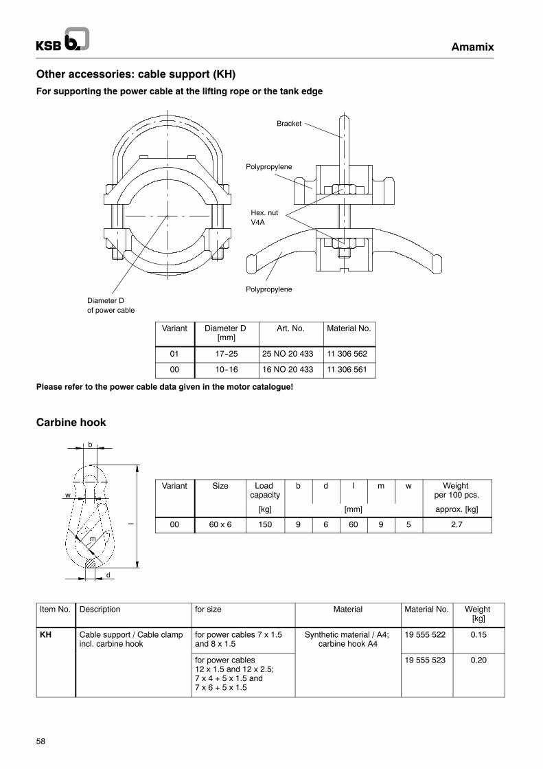
d
b
w
l
m
Amamix
58
Other accessories: cable support (KH)
For supporting the power cable at the lifting rope or the tank edge
Polypropylene
Hex. nutV4A
Polypropylene
Bracket
Diameter Dof power cable
Variant Diameter D[mm]
Art. No. Material No.
01 17--25 25 NO 20 433 11 306 562
00 10--16 16 NO 20 433 11 306 561
Please refer to the power cable data given in the motor catalogue!
Carbine hook
Variant Size Loadcapacity
b d l m w Weightper 100 pcs.
[kg] [mm] approx. [kg]
00 60 x 6 150 9 6 60 9 5 2.7
Item No. Description for size Material Material No. Weight[kg]
KH Cable support / Cable clampincl. carbine hook
for power cables 7 x 1.5and 8 x 1.5
Synthetic material / A4;carbine hook A4
19 555 522 0.15
for power cables12 x 1.5 and 12 x 2.5;7 x 4 + 5 x 1.5 and7 x 6 + 5 x 1.5
19 555 523 0.20
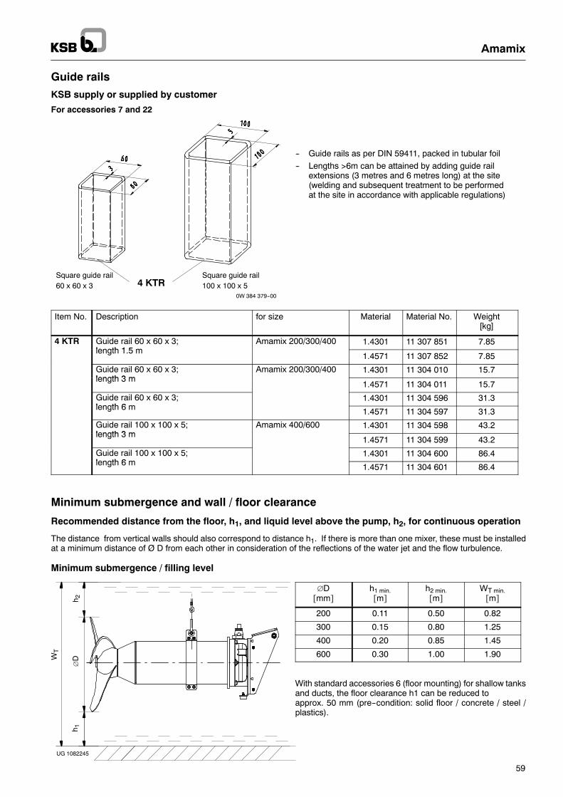
Amamix
59
Guide rails
KSB supply or supplied by customer
For accessories 7 and 22
Square guide rail60 x 60 x 3 4 KTR
Square guide rail100 x 100 x 5
0W 384 379--00
-- Guide rails as per DIN 59411, packed in tubular foil
-- Lengths >6m can be attained by adding guide railextensions (3 metres and 6 metres long) at the site(welding and subsequent treatment to be performedat the site in accordance with applicable regulations)
Item No. Description for size Material Material No. Weight[kg]
4 KTR Guide rail 60 x 60 x 3;length 1 5 m
Amamix 200/300/400 1.4301 11 307 851 7.85length 1.5 m
1.4571 11 307 852 7.85
Guide rail 60 x 60 x 3;length 3 m
Amamix 200/300/400 1.4301 11 304 010 15.7length 3 m
1.4571 11 304 011 15.7
Guide rail 60 x 60 x 3;length 6 m
1.4301 11 304 596 31.3length 6 m 1.4571 11 304 597 31.3
Guide rail 100 x 100 x 5;length 3 m
Amamix 400/600 1.4301 11 304 598 43.2length 3 m
1.4571 11 304 599 43.2
Guide rail 100 x 100 x 5;length 6 m
1.4301 11 304 600 86.4length 6 m 1.4571 11 304 601 86.4
Minimum submergence and wall / floor clearance
Recommended distance from the floor, h1, and liquid level above the pump, h2, for continuous operation
The distance from vertical walls should also correspond to distance h1. If there is more than one mixer, these must be installedat a minimum distance of Ø D from each other in consideration of the reflections of the water jet and the flow turbulence.
Minimum submergence / filling level
∅DW
T
h 1h 2
UG 1082245
∅D[mm]
h1 min.[m]
h2 min.[m]
WT min.[m]
200 0.11 0.50 0.82
300 0.15 0.80 1.25
400 0.20 0.85 1.45
600 0.30 1.00 1.90
With standard accessories 6 (floor mounting) for shallow tanksand ducts, the floor clearance h1 can be reduced toapprox. 50 mm (pre--condition: solid floor / concrete / steel /plastics).
KSB AktiengesellschaftP.O. Box 200743 • 06008 Halle (Saale) • Turmstraße 92 • 06110 Halle (Germany)Tel. +49 (345) 48 26 0 • Fax +49 (345) 48 26 46 99 • www.ksb.com
1592
.551
/6--E
N04
.201
1S
ubje
ctto
mod
ifica
tion
with
outn
otic
e
Amamix
To: KSB AktiengesellschaftTurmstr. 9206110 Halle/SaaleDept.: Competence Center Rührwerke
Fax: (+49) 345 4826 4695 Tel: (+49) 345 4826--0
From:
Project:
Data required for mixer selectionMixing duty:
Product to be mixedDescription:
Solids content: %
Temperature: oC
Density: kg/m3
Viscosity: m Pas
Loss on ignition: %
Explosion protection:
Flow behaviour
j Newtonian j Intrinsically viscous j Thixotropic
j Other:
Type of thickening
j Static j Mechanical
j Centrifuge j Screening drum
Application of polymers: j yes j no
Installation parts
j Floor mounting (access. 6) j 1.4301 j 1.4571
j Pump sump (access. 7) j 1.4301 j 1.4571
j Tank (access. 22) j 1.4301 j 1.4571
j Guide rail (access. 7 and 22) j 1.4301 j 1.4571
Process duty of tank:
Hoisting device (crane)Material: j St galv. j 1.4301 j Alu
AerationType of aeration: j None
j Pipe diffusers j Disc diffusers j Jet aerator
j Surface rotor j Plates
Air supply: m3N/h
Tank/reservoir
Material
j Concrete j Steel j Stainless steel
j Synthetic material j Steel, enamelled
Coating
Design j Covered j Open
Tank geometry
j Round j Ring channel j Square
j Rectangular j Channel
j Other:
Dimensions
Length: m
Width: m
Diameter: m
Filling level: m
Tank depth: m
Comment: