Embed Size (px)
Citation preview
AM Radio Morse Code PaddleCreated by John Park
Last updated on 2018-03-20 07:55:53 PM UTC
2335
666
6
999
11
141414151718202024
282829
33
Guide Contents
Guide ContentsOverview
PartsMaterials
Set up your Gemma M0Setup
https://adafruit.github.io/arduino-board-index/package_adafruit_index.json
Libraries
What is Morse Code?Morse CodeKeyersArduino Sketch
Build the Morse Code PaddleContact Switch InputsPaddle ConstructionClothespin ContactsPaddle BoardPivot PointContact NailSelf CenteringSwitch Wiring
AM AntennaAM AntennaDipole Experiment
Send Secret Messages
© Adafruit Industries https://learn.adafruit.com/am-radio-morse-code-paddle Page 2 of 34

Overview
Having the ability to send secret messages is a critical spy skill. By harnessing the power of radio waves and usingMorse code, you can transmit your plans to your base station for your fellow operatives!
The Gemma M0 can act as a basic AM radio transmitter by taking advantage of M0 chip's digital-to-analog converter(DAC) and direct memory access (DMA). Here's more info on how this clever hack by our own Phillip Burgess works.
You’ll tell other operatives nearby to tune in to your chosen frequency, and then you’ll send your Morse messages witha specially built Morse code keyer attached to the Gemma M0.
Parts
1 x Gemma M0Wearable microcontroller board
OUT OF STOCK
1 x Woven Conductive FabricFor building contact switches
ADD TO CART
1 x 3x AAA Battery Holderwith On/Off Switch and 2-pin JST
ADD TO CART
1 x AAA batteries3 pack
© Adafruit Industries https://learn.adafruit.com/am-radio-morse-code-paddle Page 3 of 34

ADD TO CART
1 x Enameled Copper Magnet Wiremakeshift antenna
ADD TO CART
1 x USB CableA/MicroB - 6"
ADD TO CART
© Adafruit Industries https://learn.adafruit.com/am-radio-morse-code-paddle Page 4 of 34

Materials
In addition to the above parts, you'll also need:
An AM radio to tune in the Morse transmissionsWooden clothespinSmall block of wood, approximately 2-1/2" x 5" x 3/4" (a.k.a. a 5" length of nominal 1" x 3" lumber)Two nails that fit in the clothespin spring coil and are electrically conductiveDouble stick tapeTwo small rubber bandsStranded wire or alligator clip leads
© Adafruit Industries https://learn.adafruit.com/am-radio-morse-code-paddle Page 5 of 34

Set up your Gemma M0
Setup
We’ll code this project using the Arduino IDE. First, install the Arduino IDE by following thisguide https://learn.adafruit.com/adafruit-gemma-m0/arduino-ide-setup
Arduino IDE Download
https://adafru.it/f1P
Then, follow this guide on using the Gemma M0 with the Arduino IDE https://learn.adafruit.com/adafruit-gemma-m0/using-with-arduino-ide
Be sure to set up the Arduino Preferences with this URL in the Additional Boards Manager URLs field:
https://adafruit.github.io/arduino-board-index/package_adafruit_index.json
Add the proper boards to the Board Manager for the Gemma M0:
Adafruit AVR Boards - Includes support for Flora, Gemma, Feather 32u4, Trinket, & Trinket Pro.Adafruit SAMD Boards - Includes support for Feather M0, Metro M0, Circuit Playground Express, Gemma M0and Trinket M0Arduino Leonardo & Micro MIDI-USB - This adds MIDI over USB support for the Flora, Feather 32u4, Micro andLeonardo using the arcore project.
Libraries
The Gemma M0 doesn’t have a traditional AM radio transmitter circuit built in, but it is possible to transmit by using thisclever DAC/DMA hack. https://learn.adafruit.com/circuit-playground-express-dac-hacks/overview
© Adafruit Industries https://learn.adafruit.com/am-radio-morse-code-paddle Page 6 of 34

In short, it is possible to use the digital-to-analog converter (DAC) in an unintended way by sending it messagesvery quickly using direct memory access (DMA) — so quickly that the frequency of the analog write pulses actuallygenerate AM radio waveforms!
Check out this page for more info: https://learn.adafruit.com/circuit-playground-express-dac-hacks/transmitting-am-radio
Install the ZeroDMA library as directed here https://learn.adafruit.com/circuit-playground-express-dac-hacks/overview#getting-started
Download Adafruit_ZeroDMA Library
https://adafru.it/lnd
Then, install the AMRadio library as shown here https://learn.adafruit.com/circuit-playground-express-dac-hacks/transmitting-am-radio
Download Adafruit_AMRadio Library
https://adafru.it/wAf
To test it all out, and confirm that it's all working, in Arduino open Examples > Adafruit_AMRadio > melody and uploadit to your Gemma M0. Clip a wire to the A0 pin to act as an antenna. Hold it close to an AM radio tuned to 540 AM andyou’ll hear a familiar song!
Now that we know it’s working, we’ll use a modified version of the original code to send Morse code messages,instead of tone melodies.
© Adafruit Industries https://learn.adafruit.com/am-radio-morse-code-paddle Page 7 of 34

© Adafruit Industries https://learn.adafruit.com/am-radio-morse-code-paddle Page 8 of 34

What is Morse Code?
Morse Code
Morse code follows conventions on timing for the lengths of dots and dashes, spaces between elements, spacesbetween letters, and spaces between words.
Keyers
In the original telegraph system, keyers used a single button straight key, kind of like a typewriter key, and held it forshort or long durations.
© Adafruit Industries https://learn.adafruit.com/am-radio-morse-code-paddle Page 9 of 34

An alternative to the straight key are paddles (either "bug" or "iambic" style) that can be pressed in two possibledirections — a push with the index finger is a long duration ' dash ', while a push with the thumb is a short 'dot '. Bykeeping the paddle pressed in one of the directions, it will automatically repeat with proper spacing between dots ordashes.
The letter 'D' for example, is made with a ' dash-dot-dot '. The dots and dashes are separated by inter-element gaps,
Did you know that electronics distributor Digi-Key was named after founder Ronald Stordahl's "Digi-Keyer Kit"he designed for sending radiotelegraph code? It's true!
© Adafruit Industries https://learn.adafruit.com/am-radio-morse-code-paddle Page 10 of 34

which are equal to a dot in duration, so it really looks like ' dash-gap-dot-gap-dot '.
When using a traditional straight Morse code key, the sender would use one finger to manually hold for the correct' dash ' duration, release, pause for the correct ' gap ' duration, tap a ' dot ', release, pause for ' gap ' duration, and tapanother ' dot ', and release.
A Morse code paddle automates some of this process. By tapping the paddle with the thumb from left to right, a 'dot'
is sent with the correct duration no matter if the paddle is only very quickly tapped. In other words, the timing is takencare of. By pushing the paddle with the index finger from right to left, the 'dash' duration is automatically sent. And,holding the paddle continuously repeats the dot or dash (depending on thumb or index finger direction) with theproper gap.
The Arduino code will set the dot duration at 100ms, and then derive the gap space between elements -- 1x a dot - andduration of dashes -- 3x a dot - from that.
It will be up to you to pause the appropriate time between letters (3x a dot length) and words (7x a dot length).
Here's an example: SOS . . . - - - . . . can be sent by paddling thumb and holding for three dots, index finger for threedashes, and thumb for three dots. That's only three presses with the paddle for the complete word, versus ninepresses on a traditional Morse key!
Arduino Sketch
Copy the code here, paste it into a new Arduino sketch, and then save it as AM_Radio_Morse.ino . Now, upload it to yourGemma M0 board.
© Adafruit Industries https://learn.adafruit.com/am-radio-morse-code-paddle Page 11 of 34
// For Adafruit_AMRadio library -- Morse code transmits on AM 540.// Connect antenna (40" wire) to pin A0 and GND// RANGE IS LIMITED TO A FEW FEET// Morse "dot" key is a contact switch connected to D2 and GND// "Dash" key is switch connected to D0 and GND// Adapted from Phil Burgess's AMRadio sketch
#include <Adafruit_AMRadio.h>
Adafruit_AMRadio radio;
const int buttonDotPin = 2; //pushbutton pin for ditconst int buttonDashPin = 0; //pushbutton pin for dahconst int ledPin = 13; //to light the onboard LED
int buttonDotState = 0; //to store button stateint buttonDashState = 0;
//Morse varaiblasconst int PITCH = 680;const int DOT = 100; //duration of short dot in millisconst int DASH = DOT * 3;const int GAP = DOT;
void setup() { pinMode(ledPin, OUTPUT); pinMode(buttonDotPin, INPUT_PULLUP); pinMode(buttonDashPin, INPUT_PULLUP);
radio.begin(540000); //start radio object, transmits at 540MHz AM}
void loop() { buttonDotState = digitalRead(buttonDotPin); buttonDashState = digitalRead(buttonDashPin); if (buttonDotState == HIGH) { // not pressed digitalWrite(ledPin, LOW); // light is off } else { // pressed digitalWrite(ledPin, HIGH); // light on radio.tone(PITCH, DOT); delay(GAP); } if (buttonDashState == HIGH) { // not pressed digitalWrite(ledPin, LOW); // light is off } else { // pressed digitalWrite(ledPin, HIGH); // light on radio.tone(PITCH, DASH); delay(GAP); } delay(15);}
© Adafruit Industries https://learn.adafruit.com/am-radio-morse-code-paddle Page 12 of 34

You can test this out by, again, holding the board near the AM radio tuned into 540MHz, and then use a piece of wireto bridge D0 or D2 to GND. Each time you close the contact, it will beep either a "di" or a "dah" with proper durationand spacing.
Next, we'll turn this into a proper Morse code keying paddle!
© Adafruit Industries https://learn.adafruit.com/am-radio-morse-code-paddle Page 13 of 34

Build the Morse Code Paddle
Contact Switch Inputs
In our code, the digital inputs D0 and D2 are used as switches. The pins are set to INPUT_PULLUP mode, whichmeans they will normally read HIGH , until they are sent to ground by a button press, which will cause them to readLOW .
The program checks these pins and when one goes LOW (is pressed) it broadcasts the tone for the appropriateduration, pauses for the gap duration, and repeats until the pin goes low again.
Paddle Construction
We can use any button as a key switch or pair of buttons as a paddle. If you want a more authentic paddle experience,you can build a simple one from a clothespin, a block of wood, two nails, rubber bands, and a bit of conductive fabric(or aluminum foil), some wire, and tape.
© Adafruit Industries https://learn.adafruit.com/am-radio-morse-code-paddle Page 14 of 34

Clothespin Contacts
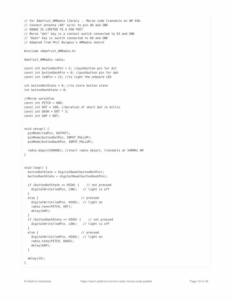
First, we'll make two contact switches on the clothespin. These will be two pieces of conductive material -- eitherconductive woven fabric, or aluminum foil -- which can be connected to the D0 and D2 pads on the Gemma M0, andwhich will be able to close the circuit to ground when they contact a nail connected to GND.
© Adafruit Industries https://learn.adafruit.com/am-radio-morse-code-paddle Page 15 of 34
First, cut two strips of the material to size so they'll
each wrap around the ends of the clothespin
Next, place a piece of double stick tape on the
material, leaving a bit of extra material on one end
for connecting your wires
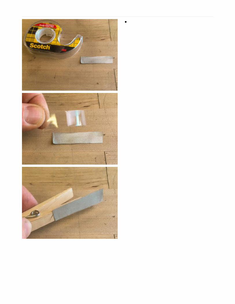
Press the material strips to the ends of the
clothespin as shown
Wrap the material around to the inside as well --
this is where it will contact the nail
© Adafruit Industries https://learn.adafruit.com/am-radio-morse-code-paddle Page 16 of 34
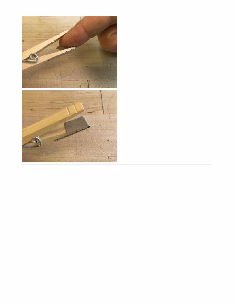
Paddle Board
Now, we'll make the base for the keying paddle, by fastening the clothespin to a small piece of wool with a nail, anddriving in another nail for the ground contact.
© Adafruit Industries https://learn.adafruit.com/am-radio-morse-code-paddle Page 17 of 34
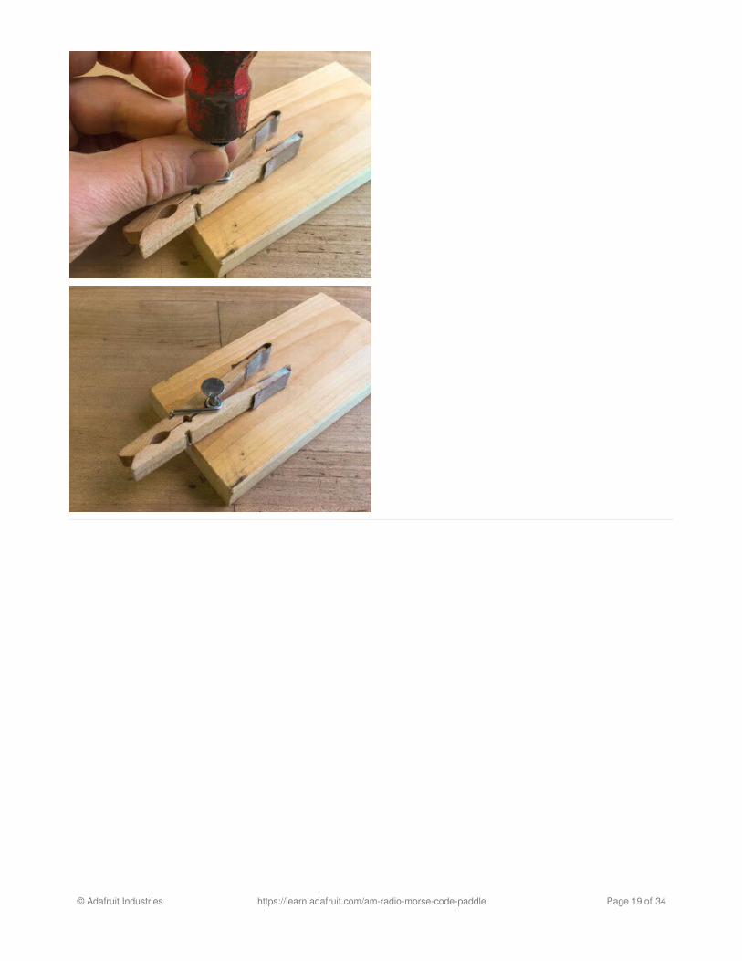
Pivot PointMeasure and mark a point in the center of the
board's width (1-1/4" from either side) and 3/4" up
from the bottom edge
Place a nail through the clothespin's spring coil
and hammer it into this marked point as shown --
be careful not to hammer too deeply or the
clothespin won't be able to rotate
© Adafruit Industries https://learn.adafruit.com/am-radio-morse-code-paddle Page 18 of 34
© Adafruit Industries https://learn.adafruit.com/am-radio-morse-code-paddle Page 19 of 34
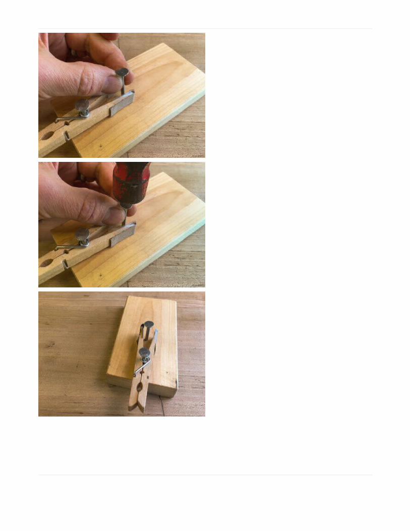
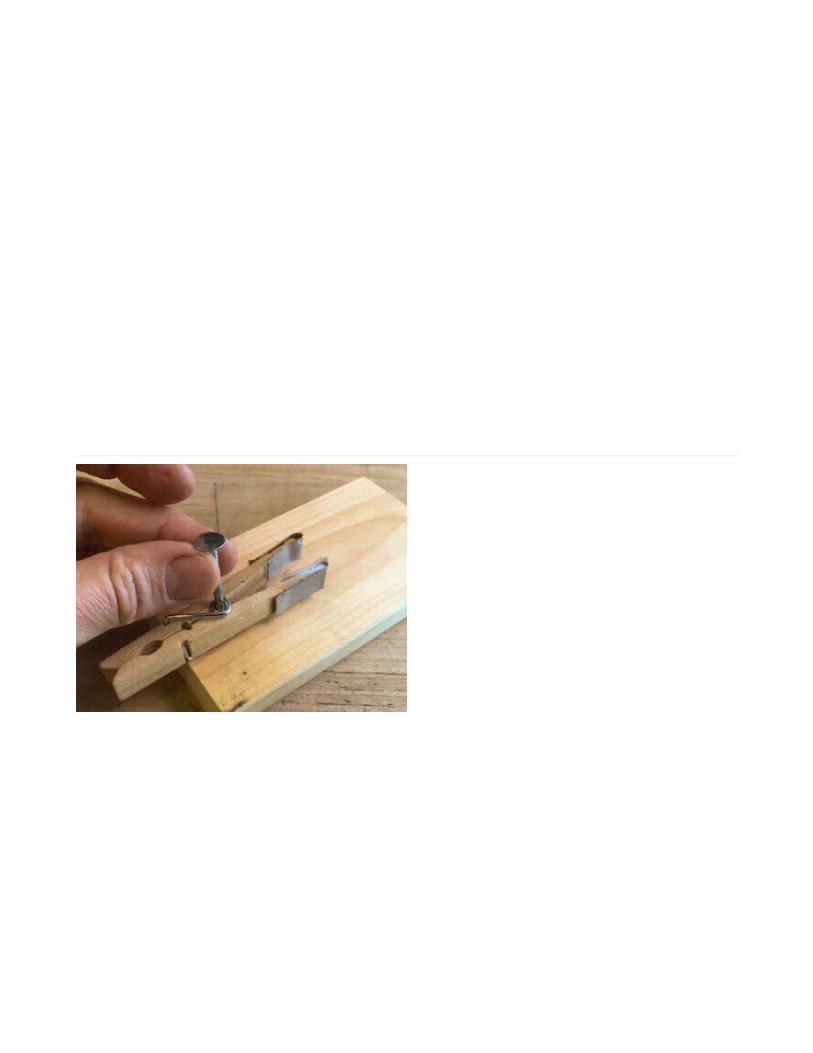
Contact NailMark a point in the center of the board's width,
about 2" up from the bottom edge -- this should be
right in the middle of the clothespin's legs
Hammer in the other nail as shown
This is the point either paddle contact will touch when
pressing the paddle from either direction.
© Adafruit Industries https://learn.adafruit.com/am-radio-morse-code-paddle Page 20 of 34

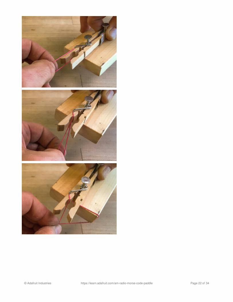
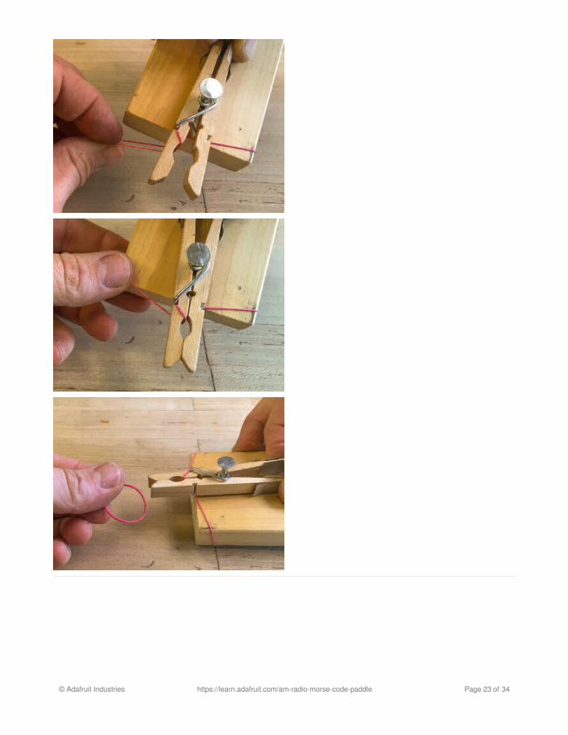
Self Centering
We want the paddle to return to its home position after every tap. To do this, we'll use a pair of rubber bands pullingequally to the left and right on the clothespin.
Squeeze the clothespin open
Loop one rubber band around the left side of the
clothespin head as shown
Twist the band to capture the head, then wrap it
around the wooden board base as shown
Repeat this for the other side
You may need to pull each band left or right to adjust it
and get the clothespin legs centered an equal distance
apart from the contact nail.
© Adafruit Industries https://learn.adafruit.com/am-radio-morse-code-paddle Page 21 of 34
© Adafruit Industries https://learn.adafruit.com/am-radio-morse-code-paddle Page 22 of 34
© Adafruit Industries https://learn.adafruit.com/am-radio-morse-code-paddle Page 23 of 34

Now you can tap the paddle from either side and test out the action! It will contact the nail and then return to homeposition.
Switch Wiring
We'll now wire the D0, D2, and GND pads on the Gemma M0 to the left, right, and ground contacts respectively on theclothespin conductive material and contact nail.
This is what the circuit looks like using regular buttons, but our contact switches will serve the same purpose as thesebuttons. We'll add an antenna wire later.
© Adafruit Industries https://learn.adafruit.com/am-radio-morse-code-paddle Page 24 of 34

Plug the Gemma M0 into the battery box, then
secure both to the end of the board with a rubber
band or tape
Connect the Gemma M0's GND pad to the contact
nail with an alligator clip lead (or twist the ends of
© Adafruit Industries https://learn.adafruit.com/am-radio-morse-code-paddle Page 25 of 34
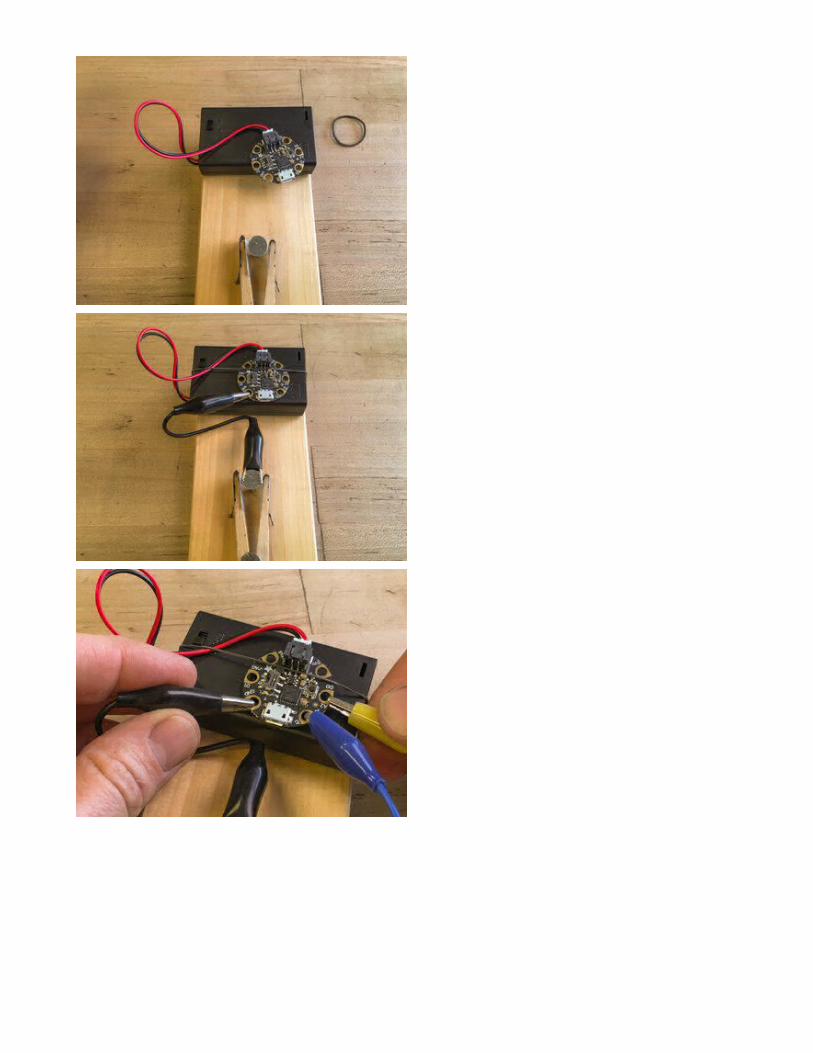
solid core hookup wire or stranded wire around
the pad and the nail if you don't have alligator clip
leads)
Connect a wire from the Gemma M0's D2 pad to
the conductive material on the right leg of the
clothespin paddle
Connect a wire from the D0 pad to the left leg
conductive material
© Adafruit Industries https://learn.adafruit.com/am-radio-morse-code-paddle Page 26 of 34

If you're eager to test your progress so far, you can turn on the battery's on/off switch and tap the paddle in eitherdirection -- you will see the on-board LED light up for a long dash when you press with your index finger, and a shortdot duration when tapped with your thumb.
But, before we can hear anything transmitted over the AM radio waves, we need to build an antenna.
© Adafruit Industries https://learn.adafruit.com/am-radio-morse-code-paddle Page 27 of 34

AM Antenna
AM Antenna
An AM radio transmitter requires an antenna to radiate its signal to the receiver. An ideal antenna would be very, verylong (usually coiled for most of this length to keep it small), but we can get a decent signal by using a 40" wire that isconnected to the output signal pad A0. (You can effectively double the range by using an 80" length of wire, and gaina bit more at 120", however beyond that the ambient noise will increase a lot.)
To make this simple antenna, measure and cut a 40" length of enamel coated copper wire (called "magnet" wirebecause it's often wound into coils to create electromagnets.)
The wire is coated in enamel, so it is electrically insulated. We need to expose a bit of the copper at onw to connect itto the Gemma M0. You can use a flame to burn away the enamel, or scrape it away carefully with a knife blade asshown here.
Use alligator clip leads to connect one of the antenna wire to A0 on the Gemma M0.
Special thanks to Jan Goolsbey for his great insights on antenna design and testing for this guide. Here are his noteson the antenna experiments he conducted:
A 40- to 80-inch long wire antenna is the better solution. After looking at the carrier and modulation waveform onthe 'scope, I began to test it without an antenna, playing with loading on the analog output pin. As the loaddropped below 5k ohms, I noticed an increase in radiated energy and signal distortion. When shorted to ground,the circuit created a distorted tone with lots of carrier sidebands, but could only be picked up by the radio withinabout 10 inches. Adding a 40-inch antenna (shorted to ground) seemed to increase the range, but only along thelength of the antenna wire -- the signal died out quickly if the radio was more than about 10 inches away from theantenna wire. Testing an open-ended 40-inch long wire was the next test. Without a ground connection, the range
© Adafruit Industries https://learn.adafruit.com/am-radio-morse-code-paddle Page 28 of 34

was about 8 to 10 feet. Adding a 40-inch ground plane wire (dipole configuration) to the ground had no noticeableeffect.
Increasing the antenna length to 80 inches almost doubled the range to 18 feet. 120 inches increased it to about25 feet. The range stayed at 25 feet when the antenna length was increased to 160 inches. The ambient noise atthe low end of the band was just too much for the Gemma to overcome even with longer antenna lengths.
I also created a helical antenna using the 160-inch antenna wire wound around a paper towel tube. The rangedropped to about a foot. In theory, 600 feet of wire wound around a tube could work if you need a more compactantenna than a 586-foot quarter-wave wire length. I'll leave that idea there for the discussion...
The basis of it is understanding how a wave travels over time. In this case, it's a 450kHz sine wave travelingthrough air at 186,272 mi/sec. Note that synchronized peak energy (the absolute value of the area under thecurve) happens at a full wavelength, 3/4, 1/2, and 1/4. Anything between those values creates a moving waveacross the length of the antenna, lowering the antenna's ability to transmit the power of the wave. Our 40-inchantenna is very inefficient since it represents only 0.0015 of the 450kHz wavelength.
Tuning an antenna is the process of reducing the destructive energy caused by wave movement across theantenna. It's accomplished by trimming the length of the antenna to match the 0.25, 0.50, 0.75, or 1.0 wavelengthnodes of the carrier wave.
Dipole Experiment
If you'd like to try some of these same experiments, here's an example of a dipole antenna, which would have equallengths of wire connected to A0 and GND.
© Adafruit Industries https://learn.adafruit.com/am-radio-morse-code-paddle Page 29 of 34

To make the dipole antenna, you'll use two wires instead. Prepare them both as before by scraping off the insulationfrom one end.
Use alligator clip leads to connect one of the antenna wires to A0 on the Gemma M0, and the other to GND.
© Adafruit Industries https://learn.adafruit.com/am-radio-morse-code-paddle Page 30 of 34

You can try out other arrangements and lengths of antennas to see how the signal strength and noise levels change.What if you orient the antenna differently? What happens if you become part of the antenna by touching the wire?
Next, we'll send some secret messages...
© Adafruit Industries https://learn.adafruit.com/am-radio-morse-code-paddle Page 31 of 34

© Adafruit Industries https://learn.adafruit.com/am-radio-morse-code-paddle Page 32 of 34

Send Secret Messages
It’s time to use your Morse paddle and transmitter to send some messages! Turn on your AM radio, tune it to 540AM,and power up the Gemma M0.
Tap out your secret messages — you could be hidden away in a secret location sending information to an operativenearby with an AM receiver and discrete earphone and nobody will ever know!
© Adafruit Industries https://learn.adafruit.com/am-radio-morse-code-paddle Page 33 of 34

© Adafruit Industries Last Updated: 2018-03-20 07:55:52 PM UTC Page 34 of 34