Embed Size (px)
Citation preview

7/31/2019 Am 60
http://slidepdf.com/reader/full/am-60 1/20
AM-60Compact DMM with
NCV & Logic Test
Users Manual• Mode d’emploi• Bedienungshandbuch• Manual d’Uso• Manual de uso

7/31/2019 Am 60
http://slidepdf.com/reader/full/am-60 2/20

7/31/2019 Am 60
http://slidepdf.com/reader/full/am-60 3/20
AM-60Compact DMM withNCV & Logic Test
Users Manual
©2009 Amprobe Test Tools.All rights reserved. Printed in China
E n g l i s h

7/31/2019 Am 60
http://slidepdf.com/reader/full/am-60 4/20
Limited Warranty and Limitation of Liability
Your Amprobe product will be ree rom deects in material and workmanship or 1 year rom thedate o purchase. This warranty does not cover uses, disposable batteries or damage rom accident,neglect, misuse, alteration, contamination, or abnormal conditions o operation or handling. Resellersare not authorized to extend any other warranty on Amprobe’s behal. To obtain service during thewarranty period, return the product with proo o purchase to an authorized Amprobe Test ToolsService Center or to an Amprobe dealer or distributor. See Repair Section or details. THIS WARRANTYIS YOUR ONLY REMEDY. ALL OTHER WARRANTIES - WHETHER EXPRESS, IMPLIED OR STAUTORY -
INCLUDING IMPLIED WARRANTIES OF FITNESS FOR A PARTICULAR PURPOSE OR MERCHANTABILITY,ARE HEREBY DISCLAIMED. MANUFACTURER SHALL NOT BE LIABLE FOR ANY SPECIAL, INDIRECT,INCIDENTAL OR CONSEQUENTIAL DAMAGES OR LOSSES, ARISING FROM ANY CAUSE OR THEORY.Since some states or countries do not allow the exclusion or limitation o an implied warranty or oincidental or consequential damages, this limitation o liability may not apply to you.
Repair
All test tools returned or warranty or non-warranty repair or or calibration should be accompaniedby the ollowing: your name, company’s name, address, telephone number, and proo o purchase.Additionally, please include a brie description o the problem or the service requested and include
the test leads with the meter. Non-warranty repair or replacement charges should be remitted in theorm o a check, a money order, credit card with expiration date, or a purchase order made payable toAmprobe® Test Tools.
In-Warranty Repairs and Replacement – All Countries
Please read the warranty statement and check your battery beore requesting repair. During thewarranty period any deective test tool can be returned to your Amprobe® Test Tools distributoror an exchange or the same or like product. Please check the “Where to Buy” section on www.amprobe.com or a list o distributors near you. Additionally, in the United States and Canada In-Warranty repair and replacement units can also be sent to a Amprobe® Test Tools Service Center(see next page or address).
Non-Warranty Repairs and Replacement – US and Canada
Non-warranty repairs in the United States and Canada should be sent to a Amprobe® Test ToolsService Center. Call Amprobe® Test Tools or inquire at your point o purchase or current repairand replacement rates.
In USA In Canada
Amprobe Test Tools Amprobe Test Tools
Everett, WA 98203 Mississauga, ON L4Z 1X9
Tel: 888-993-5853 Tel: 905-890-7600
Fax: 425-446-6390 Fax: 905-890-6866
Non-Warranty Repairs and Replacement – Europe
European non-warranty units can be replaced by your Amprobe® Test Tools distributor or anominal charge. Please check the “Where to Buy” section on www.amprobe.com or a list odistributors near you.
Amprobe® Test Tools Europe
In den Engematten 14
79286 Glottertal, Germany
tel: +49 (0) 7684 8009 - 0
*(Correspondence only – no repair or replacement available rom this address. Europeancustomers please contact your distributor.)

7/31/2019 Am 60
http://slidepdf.com/reader/full/am-60 5/20
AM-60 Compact DMM with NCV & Logic Test
1
2
3
5
64
1
2
3
3-3/4 digits 2000 counts LCD display
Push-buttons or special unctions & eatures
Selector to turn the Power On or O and select Function
Input Jack (+) current unction
Common (Ground reerence) Input Jack (-) or all unctions
Input Jack (+) or all unctions except current unction
4
5
6

7/31/2019 Am 60
http://slidepdf.com/reader/full/am-60 6/20
1
AM-60 Compact DMM with NCV & Logic Test
CONTENTS
SYMBOLS ...............................................................................................................2
UNPACKING AND INSPECTION ............................................................................3
INTRODUCTION .....................................................................................................4OPERATION ............................................................................................................4
SPECIFICATION ......................................................................................................8
MAINTENANCE ......................................................................................................12
TROUBLE SHOOTING.............................................................................................12
Fuse Replacement ............................................................................................13
Battery Replacement .......................................................................................13

7/31/2019 Am 60
http://slidepdf.com/reader/full/am-60 7/20
2
SYMBOLS
X Warning! Dangerous Voltage (Risk o electric shock).
Caution ! Reer to the user’s manual beore using this Meter.
T Double Insulation or Reinorced insulation
B Alternating Current (AC).
F Direct Current (DC).
N Low battery indicator
I Fuse
JGround (maximum permitted voltage between terminal and
ground).
Please remove all the test leads beore preorming maintenance,
cleaning, battery replacement, use replacement, etc
Complies with European Directives
� Conorms to relevant Australian standards
=Do not dispose o this pruduct as unsorted municipal waste.
Contact a qualifed recycler or disposal
Warnings!
• Do not operate this meter in explosive gas (material), combustible gas(material) steam or flled with dust.
• When using test leads or probes, keep your ngers behind the ngerguards.
• Remove test lead from Meter before opening the battery door or Meter
case.• Use the Meter only as specied in this manual or the protection by the
Meter might be impaired.
• Always use proper terminals, switch position, and range formeasurements.
• Never attempt a voltage measurement with the test lead inserted intothe A input terminal.
• Verify the Meter’s operation by measuring a known voltage. If in doubt,
have the Meter serviced.

7/31/2019 Am 60
http://slidepdf.com/reader/full/am-60 8/20
3
• Do not apply more than the rated voltage, as marked on Meter,between terminals or between any terminal and earth ground.
• Do not attempt a current measurement when the open voltage is abovethe use protection rating.
• Suspected open circuit voltage can be checked with voltage function.
• Only replace the blown fuse with the proper rating as specied in thismanual.
• Use caution with voltages above 30 Vac rms, 42 Vac peak , or 60 Vdc.These voltages pose a shock hazard.
• To avoid false readings that can lead to electric shock and injury, replace
battery as soon as low battery indicatorN appears.
• Disconnect circuit power and discharge all high-voltage capacitorsbeore testing resistance, continuity, diodes, or capacitance.
• Do not use Meter around explosive gas or vapor.
• To reduce the risk of re or electric shock do not expose this product torain or moisture.
• Disconnect the test leads from the test points before changing theposition o the unction rotary switch.
• Never connect a source of voltage with the function rotary switch in
e / G / FBA / E /Hz position.
• Do not expose Meter to extremes in temperature or high humidity.
• Never set the meter in FBA unction to measure the voltage o a powersupply circuit in equipment that could result in damage the meter andthe equipment under test.
UNPACKING AND INSPECTION
Your shipping carton should include:
1 AM-60 Meter
2 Test Leads
2 Battery (SIZE AAA, 1.5V)
1 User’s Manual
I any o the items are damaged or missing, return the complete package to
the place o purchase or an exchange.

7/31/2019 Am 60
http://slidepdf.com/reader/full/am-60 9/20
4
INTRODUCTION
Multimeter AM-60 can be used to measure voltage, resistance, capacitance,requency, current; It is an electronic measuring instrument that combinesseveral measurement unctions in one unit. AM-60 multimeter is portablehand-held devices useul or basic ault fnding and feld service work or abench instrument which can measure to a very high degree o accuracy. They
can be used to troubleshoot electrical problems in a wide array o industrialand household devices such as batteries, motor controls, appliances, powersupplies, and wiring systems.
OPERATION
Measuring AC/DC Voltage And Frequency
Testing for Continuity and Diode

7/31/2019 Am 60
http://slidepdf.com/reader/full/am-60 10/20
5
Resistance and Capacitance
Note – To improve the measurement accuracy o small value capacitor, record
the reading with the test leads open then substract the residual capacitance othe Meter and leads rom measurement.
CUNKNOWN = CMEASUREMENT - CRESIDUAL
MIN MAX Record
Measuring DC / AC Current
7/31/2019 Am 60
http://slidepdf.com/reader/full/am-60 11/20
6
Display Hold
Manual Ranging and Auto Ranging
Auto Power Off (Battery Saver)

7/31/2019 Am 60
http://slidepdf.com/reader/full/am-60 12/20
7
Disable Auto Power Off
Non-Contact Voltage (Volt sense)
1. Volt sense switch will be activated on any unction or at OFF status.2. Test leads are not used or the Volt sense test.3. Press the Volt sense button. The display goes black, a tone sounds and
the red LED lights up to veriy the instrument is operational. The Voltsense button must be held down to detect the presence o voltagewithout use o the leads.
4. I a voltage o 50V to 600V (50 to 500Hz) is detected near the top ometer a continuous tone sounds and the red LED near the top o meterIlluminates.

7/31/2019 Am 60
http://slidepdf.com/reader/full/am-60 13/20
8
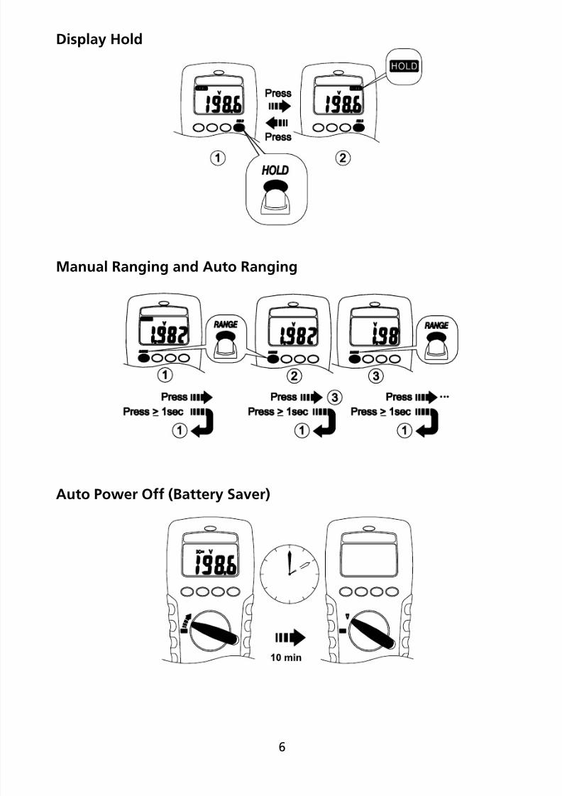
SPECIFICATIONS
General Specications
Display : 2000 counts.
Polarity Indication : Automatic, positive implied, negative
indicated.
Overrange Indication : “OL” or “-OL”.
Batteries Lie : Alkaline 250 hours
Low Batteries Indication : “N” is displayed when the batteries voltage
drops below operating voltage.
Auto Power Off : Approx 10 minutes.
Operating Ambient : Non-condensing≦50°F, 51.8°F ~ 86°F
(≦80% R.H) 87.8°F ~ 104°F (≦75% R.H),
105.8°F ~ 122°F (≦45% R.H)Storage Temperature : -4°F to 140°F , 0 to 80% R.H. when battery
removed rom Meter.
Temperature Coefcient :0.15 x (Spec. Accy) /°F ,< 64.4°F or >
82.4°F.
Measure : Samples 2 times per second nominal.
Altitude : 6561.7 t (2000m)
Safety : Complies with EN61010-1, UL61010-1,
IEC 61010-1,
V/e : CAT.III. 600V, CAT.II. 1000V.
A : CAT.III. 500V
Pollution degree : 2
Power Requirements : 1.5V x 2 IEC LR03, AM4 or AAA size
Dimensions (W x H x D) : 74mm (2.9”) x 156mm (6.1”) x 44mm (1.7”)
Weight : 320g (0.71lb) including battery.
Accessories : Battery (installed), Test leads and user manual.
Electrical Specications
Accuracy is ±(% reading + number o digits) at 23°C ± 5°C < 80%RH.

7/31/2019 Am 60
http://slidepdf.com/reader/full/am-60 14/20
9
DC / AC Volts
Range AC Accuracy
200.0mV * Unspecifed
2.000V * ±(1.5%+5dgt) 50Hz ~ 300Hz
20.00V ~ 200.0V *±(1.5%+5dgt) 50Hz ~ 500Hz
750V AC / 1000V DC
DC Accuracy : ±(0.5% + 2dgt)
Over voltage protection : 1000V DC or 750 V ACrms.
Input Impedance : 10Me // less than 100pF.
* CMRR / NMRR : (Common Mode Rejection Ratio)
(Normal Mode Rejection Ratio)
VAC : CMRR > 60dB at DC, 50Hz / 60Hz
VDC : CMRR > 100dB at DC, 50Hz / 60Hz
NMRR > 50dB at DC, 50Hz / 60Hz
AC Conversion Type :
Average sensing rms indication.
AC conversions are ac-coupled, true rms responding,
calibrated to the sine wave input.
* The minimum LCD reading is 1400 count in Auto Ranging Mode.
Crest Factor : C.F. = Peak / Rms
+ 1.5% addition error or C.F. rom 1.4 to 3
+ 3% addition error or C.F. rom 3 to 4
DC / AC Current
Range DC Accuracy AC AccuracyVoltage
Burden
2.000A
±(1.0% + 3 dgt)
±(1.5% + 5 dgt)
50Hz ~ 500Hz
*
2V max10.00A **
Overload Protection :
A input : 10A (500V) ast blow use

7/31/2019 Am 60
http://slidepdf.com/reader/full/am-60 15/20
10
* AC Conversion Type : Conversion type and additional specifcation are same
as DC/AC Voltage.
** Ampere Testing Duty Ratio Table
Ampere Testing Time Rest Time
10A 1min 10min
9A 2min 10min
8A 3min 10min
7A 4min 10min
6A 5min 10min
5A Continually N/A
Resistance
Range Accuracy Voltage Burden
200.0~200.0Ke ** ±(0.7% + 3 dgt)
2V max2.000Me ** ±(1.0% + 3 dgt)
20.00Me * ±(1.5% + 3 dgt)
Open circuit Voltage: -1.3V approx.
* < 100 dgt rolling.
** The minimum LCD reading is 1400 count in Auto Ranging Mode.
Diode Check and Continuity
Resolution Accuracy
10 mV ±(1.5% + 5 dgt)*
* For 0.4V ~ 0.8V
Max.Test Current : 1.5mA
Max. Open Circuit Voltage : 2V
Overload Protection : 600V rms.
7/31/2019 Am 60
http://slidepdf.com/reader/full/am-60 16/20

7/31/2019 Am 60
http://slidepdf.com/reader/full/am-60 17/20
12
MAINTENACE
I there appears to be a malunction during the operation o the meter, theollowing steps should be perormed in order to isolate the cause o theproblem.
1. Check the battery. Replace the battery immediately when the “N”
symbol appears on the LCD.2. Review the operating instructions or possible mistakes in operatingprocedure.
Except or the replacement o the battery, repair o the meter should beperormed only by a Factory Authorized Service Center or by other qualifedinstrument service personnel. The ront panel and case can be cleaned witha mild solution o detergent and water. Apply sparingly with a sot cloth andallow to dry completely beore using. Do not use aromatic hydrocarbons orchlorinated solvents or cleaning. I the meter is not to be used or periods o
longer than 60 days, remove the batteries and store them separatelyDo not attempt to repair this Meter. It contains no user-serviceable parts.Repair or servicing should only be perormed by qualifed personnel.
TROUBLE SHOOTING
I the instrument ails to operate, check batteries and test leads etc., andreplace as necessary. Double check operating procedure as described in this
user’s manual.
If the instrument voltage-resistance input terminal has subjected to highvoltage transient (caused by lightning or switching surge to the system) byaccident or abnormal conditions o operation, the series usible resistors willbe blown o (become high impedance) like uses to protect the user and theinstrument. Most measuring unctions through this terminal will then be opencircuit. The series usible resistors and the spark gaps should then be replacedby qualifed technician. Reer to the LIMITED WARRANTY section or obtaining
warranty or repairing service.

7/31/2019 Am 60
http://slidepdf.com/reader/full/am-60 18/20
13
Fuse Replacement
Reer to the ollowing fgure to replace use :
CAUTION:
• Use only a fuse with the amperage, interrupt, voltage, and speed ratingspecifed.
• Fuse rating : 10A, 500V
Battery ReplacementReer to the ollowing fgure to replace the batteries:
1
2
3
4
1
2
3

7/31/2019 Am 60
http://slidepdf.com/reader/full/am-60 19/20

7/31/2019 Am 60
http://slidepdf.com/reader/full/am-60 20/20


![You Said Something [from the musical 'Have a Heart'] · JEROME KERN .60 .60 And I Am All Alone .60 Polly Believed In Preparedness .60 Honeymoon Inn .60 Napoleon .60 I'm so Busy .60](https://img.pdfslide.us/doc/110x75/5b5c13737f8b9ad21d8b75fb/you-said-something-from-the-musical-have-a-heart-jerome-kern-60-60-and.jpg)