Embed Size (px)
Citation preview

© 2016 CPT Autopilot Inc. Version 16
CPT Autopilot Installation Manual
The CPT has been installed in a large variety of sailing and motor vessels, in many different installations.
This manual will help you install, operate, and maintain your CPT.
Mounting the CPT on a pedestal or bulkhead is a quick and easy installation. This manual also has advice
for alternative installations, including slanted gear-driven wheels, wooden wheels, and large oversized
wheels. This manual will help you choose the best installation method for your boat.
The CPT is an extra crew member to man the wheel, day or night, rain or shine. It is amazing to take your
hands off the wheel and experience the freedom the CPT provides.
Always remember to maintain a proper look-out:
Warning! Do not use the CPT in traffic or in waters where navigation is restricted!
An autopilot is NOT a substitute for good seamanship. Always maintain a permanent watch by the
helm.
INTERNATIONAL REGULATIONS FOR PREVENTING COLLISIONS AT SEA, 1972 (72 COLREGS)
Part B - Steering and Sailing Rules
Section 1 - Conduct of Vessels in any Condition of Visibility
Rule 5 - Lookout
Every vessel shall at all times maintain a proper look-out by sight and hearing as well as by all available means
appropriate in the prevailing circumstances and conditions so as to make a full appraisal of the situation and risk of
collision.
WARNING!
KEEP CHILDREN & PETS AWAY
FROM THE CPT BELT.

Page 2 of 21
HOW TO USE THE CPT MANUAL
1. Review the “Basic Mounting Requirements and Types of Installations” on page 6 to see how the CPT
can best be mounted in your cockpit. The standard pedestal, bulkhead, or L-bracket mounts are the
easiest, most straightforward installations. Review “Part I—Installation” for more detailed information.
2. Download installation templates from our website at www.cptautopilot.com. Print the templates and
use them to get the measurements for mounting your CPT. Order your CPT and submit your basic
measurements through our website, or by calling us at 831-687-0541
3. When your CPT arrives, follow instructions in “Part I, Installation” for installing the CPT.
Then perform the “Dockside Check-Out” and “Sea Trials”.
4. To become more familiar with the CPT, review the CPT Operation Manual.
If you have any questions or suggestions for improving this manual, please let us know. We are
always pleased to receive photos of CPT installations and suggestions for improving the CPT.
MANUFACTURED AND SOLD DIRECT BY
CPT AUTOPILOT INC. 7960 B Soquel Drive, #114, Aptos, CA 95003 USA
www.cptautopilot.com email: [email protected]

Page 3 of 21
PART I – INSTALLATION .................................................................................................................. 4
1. Parts List .................................................................................................................................... 4
2. Installation Summary .................................................................................................................... 4
A. Standard Pedestal Mount, L-Bracket Mount, or Bulkhead Mount: * ................................................... 5
B. Reversed Motor Box; L-Bracket, Pedestal, or Bulkhead Mount *...................................................... 5
4. Mounting The Wheel Pulley ........................................................................................................... 6
A. Wheels with Metal Spokes:........................................................................................................ 6
B. Wheels with Wooden Spokes ..................................................................................................... 8
5. Mounting The Motor Box (only after Wheel Pulley is mounted) ............................................................ 9
A. Standard Pedestal Mount: .......................................................................................................... 9
B. L-Bracket Mount; Sidewall or Cockpit Sole Mount....................................................................... 11
C. Bulkhead Mount; Console or Square Pedestal Mount .................................................................... 12
D. Tilted or Angled Wheels ......................................................................................................... 14
E. Oversize and Large Wheels ...................................................................................................... 14
F. Reverse Pedestal Mount; Large Wheels or Limited Helm Space ...................................................... 15
G. Mounting Problems Not Addressed ........................................................................................... 15
6. Electrical Connection .................................................................................................................. 16
Splicing Control Box Cable: ............................................................................................................ 16
A. Changing the rotation of the wheel & small drive pulley.................................................................... 16
Standard installations with the drive-pulley facing forward .................................................................... 16
Reverse-mounting with the drive pulley facing aft: ............................................................................... 16
B. Setting the Magnetic Reference:.................................................................................................... 17
7. Mounting the Control Box............................................................................................................ 17
A. Control Box Mounting Requirements......................................................................................... 18
B. Testing the Control Box before final mounting ............................................................................ 18
C. Troubleshooting..................................................................................................................... 19
8. How to check for magnetic interference .......................................................................................... 20
Page 4 of 21
PART I – INSTALLATION
1. Parts List
Before beginning the installation, unpack and identify all parts.
Standard Parts
• Motor box (larger box with clutch/gear on back) w/10' power cable
• Control box w/heading controls, attached to motor box w/10' cable)
• Wheel pulley (for clamping to steering wheel)
• Drive belt
• 316 stainless J-bolts with nuts & washers (quantity & length to suit boat's wheel)
• Short Control box Bracket for pedestal rail & bulkhead mounting or Long Control box Bracket for
console & overhead mounting: specify when ordering. Peel off white or grey plastic protective
covering.
• Motor box bracket for mounting Motor box to bulkhead or pedestal kit
• Carriage bolt with wing-nut, & washer for mounting Motor Box
• Spare shear pin set
• In-line fuse
• This manual
Additional Parts, If Ordered
• Pedestal mount kit (standard or shallow) with hardware, hose clamps and anti-scratch rubber pads.
Peel off white plastic protective covering.
• L-bracket, Drop-down plate, or Reverse-mounting plate for mounting Motor box
• Waterproof plug & receptacle for 12-volt power supply
• Extra belts
• Extra shear pin sets
• Shim pads if needed for mounting motor box, spacers for wheel pulley if needed
• Custom cable lengths for power cable and control box cable
• Miscellaneous spares, as ordered
2. Installation Summary
Installation requires:
A. Mounting the large wheel pulley onto the steering wheel. (page 6)
B. Mounting the motor box on pedestal, bulkhead, console or deck. (page 8)
C. Running the power cable to the 12-volt power source. (page Error! Bookmark not defined.)
D. Mounting the control box. (page 16)
This installation can normally be completed in an afternoon, depending on the particular boat, installer, &
ease of wheel removal.
The power & control box cables are not removable. The black cable fittings are not
removable plugs and should not be loosened or disturbed due to the watertight seals. Do not
attempt to open the control box or motor box, there are no user serviceable parts inside.
Loosening the black cable fittings or opening the unit will void your warranty.
Do not cut any wires or fit owner plugs until after sea trials, when you are sure of the
installation! If you wish to run power or control box cable through a deck or bulkhead,
the cable can later be cut at a point where the splice will be inside and dry. The standard
cable length is 10 ft, let us know if a longer length is needed at the time of ordering. The
Page 5 of 21
control box cable is six-conductor, color-coded & shielded. Solder & heat-shrink the
splices, or use a terminal block with soldered lugs, keeping the splice or terminal block
shielded. A waterproof connector may be used on the power line. (See “Electrical
Connection”)
3. Basic Mounting Requirements and Types of Installations
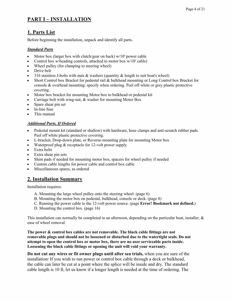
A. Standard Pedestal Mount, L-Bracket Mount, or Bulkhead Mount: *
• Recommended standard mounting; clutch/small drive-pulley facing forward
• Motor Box mounted with pedestal mounting kit (pg 8) or directly to bulkhead (pg 11)
• Motor Box mounted on PORT side of wheel with L-Bracket to deck or sidewall
Minimum of 2 ¾" needed
between spokes and pedestal.
2 ¾" to 4" uses shallow
pedestal bracket; over 4" uses
standard pedestal bracket.
L-Bracket
Mount
Pedestal
Mount Bottom of drive box to deck
2 ¾" minimum clearance
Wheel to deck
7 ¾" minimum clearance
B. Reversed Motor Box; L-Bracket, Pedestal, or Bulkhead Mount *
• For installations where space is restricted. Motor Box is reversed, with clutch facing AFT.
• Motor Box mounted on Starboard side of wheel with L-Bracket to deck or sidewall
• Motor Box can be mounted completely forward of the wheel & inside the perimeter of the wheel
(rather than below & aft of the wheel) by using a spacer ring or individual spacers on the wheel
pulley to allow operation of the clutch. (contact us for details)
Page 6 of 21
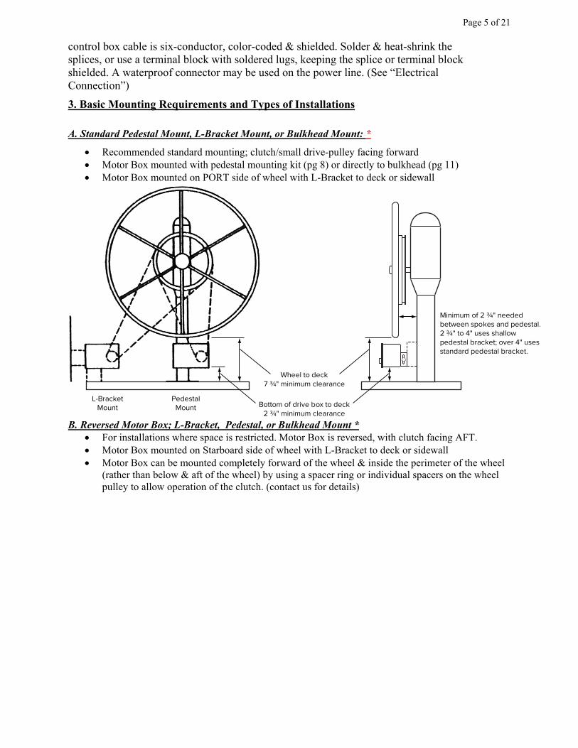
• Motor box mounted on the pedestal to PORT w/ reverse-plate, 19”min belt size (see “F. page
13)
Bottom of drive box to deck
2 ¾" minimum clearance
Wheel to deck
7 ¾" minimum clearance
Minimum of 2 ¾" needed
between spokes and pedestal.
2 ¾" to 4" uses shallow
pedestal bracket; over 4" uses
standard pedestal bracket.
Bottom of drive box to deck
2 ¾" minimum clearance
Wheel to deck
7 ¾" minimum clearance
L-Bracket
Mount
Pedestal
Mount
4. Mounting The Wheel Pulley
A. Wheels with Metal Spokes:
1. **DO NOT OVERTIGHTEN J-bolts** Tighten the nut until the back of the J-bolt
grips the spoke and just begins to resist swinging, then turn the nut only another ¼
turn. Do not over tighten J-bolts or the pulley will eventually warp or distort. If
there is a gap between the spoke and pulley, a shim must be used to fill the gap; do not
tighten J-bolt to lessen the gap or the pulley will distort and warp. With tapered or dished
wheels there will be a gap at the outer edge of the pulley, and contact will be made only on
the inside edge; tapered spokes or dished wheels may require angled shims if the gap is
large.
2. Remove the steering wheel. (On older boats, this may require a gear puller. Grease shaft
before replacing the wheel and you will have less trouble next time.)
3. Place the Wheel Pulley on back of wheel, thick flange against spokes. Hook J-Bolts
provided around spokes, and pass them through holes in pulley. Center pulley approximately
on the wheel. J-bolts should all point the same way clockwise or counter-clockwise around
the wheel. Put a drop of oil, flat washer and a nut on each J-bolt.
4. Inspect fit of pulley against spokes. If steering wheel spokes are out of alignment or not in
plane, and show a gap or space with the pulley, low spokes must be
shimmed. DO NOT attempt to pull them into alignment by
tightening the J-bolts – the pulley will warp and distort. On
dished wheels or if spokes are tapered, if the gap on the outside edge
is large, use tapered shims of teak, pieces of pvc or acrylic between
pulley and spokes to even the backing on the pulley.
5. Temporarily remount steering wheel (with mounted pulley). Overlong
J-bolt stems can be cut off flush later.
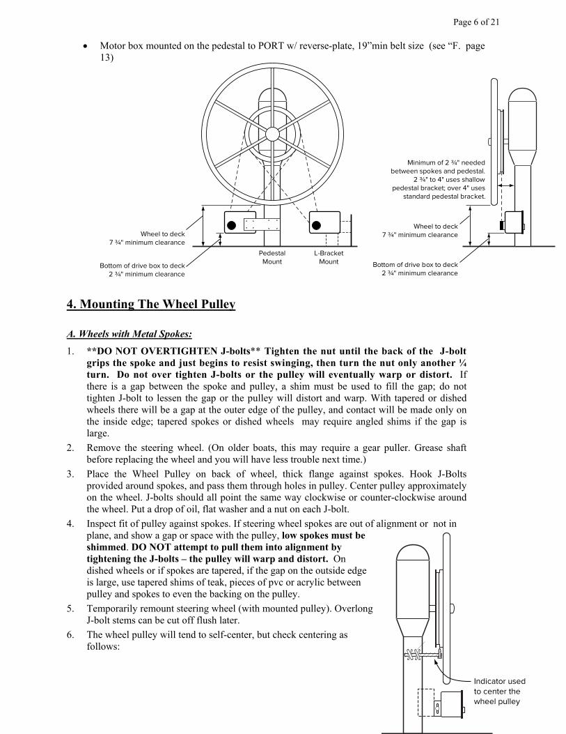
6. The wheel pulley will tend to self-center, but check centering as
follows:
Indicator used
to center the
wheel pulley

Page 7 of 21
a) As an indicator, mount a tool (a taped coffee stick, or coat-hanger taped to the pedestal, for
example) with its tip close to pulley. Tape it solidly to pedestal so it does not move.
b) Rotate the wheel.
c) Use your hand to tap the pulley to adjust its center position until distance between pulley and
pointer is fairly uniform, +/- 1/8” is fine.
d) Tighten J-bolt nuts. Use a nut driver or small wrench: tighten the nut until the back of the J-
bolt grips the spoke and just begins to resist swinging, then turn the nut only another ¼ turn
(35 inch-Lbs max.).
e) With large wheels, place the belt on wheel pulley before putting wheel back onto shaft.
(belt may not fit over large wheels)

Page 8 of 21
B. Wheels with Wooden Spokes
Proceed in the same general fashion as for metal-spoked wheels. If preferred the spokes can be padded
to prevent crushing the wood or damaging the varnish under J-bolts. Clear vinyl tubing cut to length
and slipped over J-bolt hooks works well.
If you prefer not to use J-bolts, you may screw the pulley to wheel directly with self-tapping or wood
screws (Use pan-head screws with washers, not flat-head screws):
1. Temporarily fasten pulley to wheel with tape or a lashing of light line.
2. Center pulley as described under “Metal-Spoked Wheels”.
3. Mark and drill pilot holes in wooden spokes for fasteners.
4. If desired, use bedding compound in the holes to fill any gap with the fasteners used.
Page 9 of 21
5. Mounting The Motor Box (only after Wheel Pulley is mounted)
A) STANDARD PEDESTAL MOUNT (below): The CPT's Pedestal Bracket is designed to mount
on most pedestals - it comes in two sizes (shallow bracket for spoke-to pedestal clearances from
2-3/4” to 3-3/4”, and deep bracket for spoke-to-pedestal clearances over 3-3/4”). The pedestal
bracket uses the motor box bracket to hold the motor box assembly.
B) L-BRACKET MOUNT (on page 11): Mounting on a surface that is parallel to wheel shaft, such
as a coaming, sidewall, deck or cabin sole requires the L-bracket. The L-bracket also uses the
motor box bracket to hold the motor box assembly.
C) BULKHEAD MOUNT (on page 12): The motor box bracket by itself can be used with
appropriate shims to mount the motor box assembly directly onto a console or bulkhead parallel
to the boat's wheel. Teak or marine-board shims are used to align the drive belt with the wheel.
D) TILTED WHEELS (on page 14): The L-bracket is used to mount motor box on cockpit sole or
cockpit side-wall for boats with tilted wheels or slanted gear-driven wheels.
E) OVERSIZED WHEELS (on page 14): The L-bracket is used to mount motor box to deck or
sidewall in boats with large wheels, or “Deck-sweeper” wheels.
F) PEDESTAL REVERSE MOUNT (on page 15): An optional method for mounting motor box
using pedestal bracket with a shimmed offset reverse-plate to reverse and place the motor box
forward of the wheel.
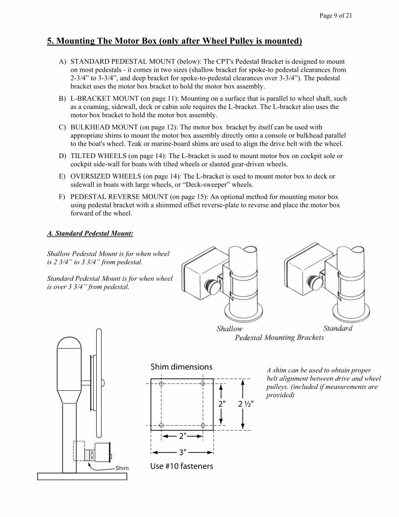
A. Standard Pedestal Mount:
Shallow Pedestal Mount is for when wheel
is 2 3/4” to 3 3/4” from pedestal.
Standard Pedestal Mount is for when wheel
is over 3 3/4” from pedestal.
Shim Use #10 fasteners
3"
2"
2" 2 ½"
Shim dimensions A shim can be used to obtain proper
belt alignment between drive and wheel
pulleys. (included if measurements are
provided)
Page 10 of 21
Note: If pedestal diameter is less than 3-3/4”, hose-clamps alone may not provide adequate support.
(Use clamps temporarily to hold bracket in place for drilling) Proceed as directed, but use holes in the
four corners of pedestal mounting bracket as a guide and drill four holes for #10 self-tapping screws,
or drill and tap for #10 machine screws.
1. Hang the belt on wheel pulley, between flanges.
2. Bolt motor box bracket to pedestal bracket using the four #10 fasteners, along with any shims (if
needed for belt alignment) Sides of bracket should be vertical at the sides of Pedestal Bracket.
3. Take the assembly and position the motor box bracket over fitting on back of Motor Box, and fasten
them together with the bolt, washer, and wing nut . Orient the bracket so the 4 offset holes in the
pedestal mount on the bottom. Tighten the carriage bolt midway & centered in the slots.
With the belt on the wheel, place the drive-gear of the motor box in the belt. Allow the motor box
and pedestal bracket assembly to hang in the belt and rest snug against the pedestal while you support
it. Check belt for a clear run between pulleys with no interference or rubbing.
Starting from inside the bracket, pass the hose clamps through the slots (from the side with the 2
holes) and around the pedestal stem & loosely tighten. Adjust the pedestal bracket so that the
stainless edge of the bracket is 1” from the pedestal if using the shallow bracket, or 2-1/2” if
using the deep bracket (check at both the top and bottom of the bracket). Tighten hose clamps
enough to hold the assembly in position.
4. Check for alignment: hold a yardstick or straight-edge against the back of the wheel adapter; it should
be fairly parallel with the belt when viewed from the side (clutch engaged & pushed in). Also look
from above the wheel and from the side to be sure the motor box is square with the wheel from all
directions and not at an angle. If in doubt or your wheel is not uniform, favor a slight belt slant that
will help keep the clutch engaged. If the belt is not parallel you can squeeze the stainless bracket
deeper or shallower on the pedestal as needed, or add or remove a shim. Re-tighten clamps after 2-
3 days, as the rubber compresses.
5. Tension belt by sliding motor box down in the slots with hand pressure and tightening the wing-nuts.
Do not over-tension the belt. Tensioning tools are not needed; if it’s snug it’s tight enough.
An over-tensioned belt will wear motor bearings, belt and clutch, & make the clutch hard to
operate. If the wheel pulley is not centered the motor shaft can shear.
Page 11 of 21
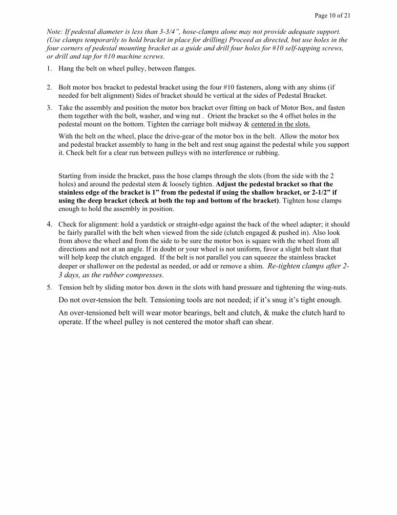
Drop-Down Plate: Pedestal Mount, limited deck clearance
If there is a minimum space of 7-1/2” between wheel rim and
cockpit sole, but the pedestal base is too high to allow the stainless
steel pedestal bracket to fasten, a “dropped” installation can be
used. Insert a sturdy metal or marine board plate to the pedestal
bracket. CPT Autopilot can determine exactly what is needed if
customer helm measurements are provided; a predrilled stainless
or anodized drop-down plate is available.
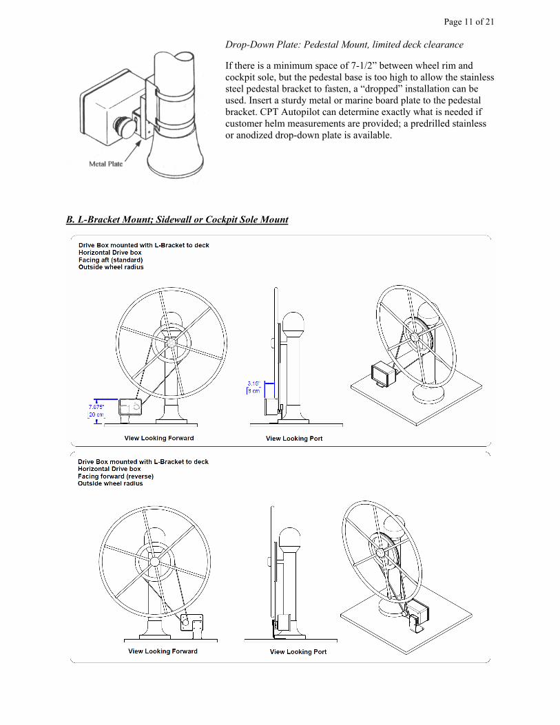
B. L-Bracket Mount; Sidewall or Cockpit Sole Mount
Page 12 of 21
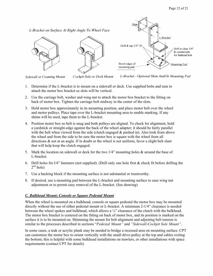
1. Determine if the L-bracket is to mount on a sidewall or deck. Use supplied bolts and nuts to
attach the motor box bracket so slots will be vertical.
2. Use the carriage bolt, washer and wing nut to attach the motor box bracket to the fitting on
back of motor box. Tighten the carriage bolt midway in the center of the slots.
3. Hold motor box approximately in its mounting position, and place motor belt over the wheel
and motor pulleys. Place tape over the L-bracket mounting area to enable marking. If any
shims will be used, tape them to the L-bracket.
4. Position motor box so belt is snug and both pulleys are aligned. To check for alignment, hold
a yardstick or straight-edge against the back of the wheel adapter; it should be fairly parallel
with the belt when viewed from the side (clutch engaged & pushed in). Also look from above
the wheel and from the side to be sure the motor box is square with the wheel from all
directions & not at an angle. If in doubt or the wheel is not uniform, favor a slight belt slant
that will help keep the clutch engaged.
5. Mark the location on sidewall or deck for the two 1/4” mounting holes & around the base of
L-bracket.
6. Drill holes for l/4” fasteners (not supplied). (Drill only one hole first & check fit before drilling the
2nd hole)
7. Use a backing block if the mounting surface is not substantial or trustworthy.
8. If desired, use a mounting pad between the L-bracket and mounting surface to ease wing nut
adjustment or to permit easy removal of the L-bracket. (See drawing)
C. Bulkhead Mount; Console or Square Pedestal Mount
When the wheel is mounted on a bulkhead, console or square pedestal the motor box may be mounted
directly without the use of either pedestal mount or L-bracket. A minimum 2-1/4” clearance is needed
between the wheel spokes and bulkhead, which allows a ¼” clearance of the clutch with the bulkhead.
The motor box bracket is centered on the fitting on back of motor box, and its position is marked on the
surface it is to be mounted on. Shimming the mount for belt alignment and adjusting belt tension is
similar to the processes described in sections “Pedestal Mount” and “Sidewall-Cockpit Sole Mount”.
In some cases, a teak or acrylic plank may be needed to bridge a recessed area on mounting surface. CPT
can customize the motor box to orient vertically with the small drive-pulley at the top and cables exiting
the bottom; this is helpful with some bulkhead installations on trawlers, or other installations with space
requirements (contact CPT for details)
L-Bracket on Surface At Right Angle To Wheel Face
Page 13 of 21
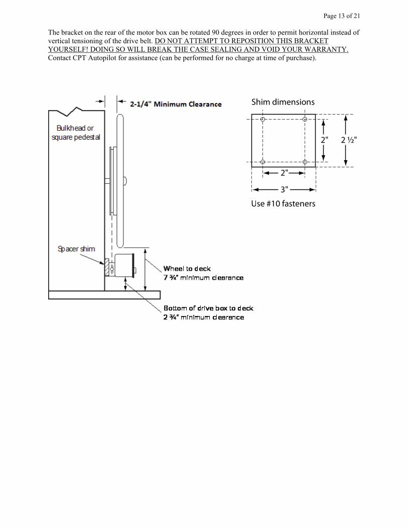
The bracket on the rear of the motor box can be rotated 90 degrees in order to permit horizontal instead of
vertical tensioning of the drive belt. DO NOT ATTEMPT TO REPOSITION THIS BRACKET
YOURSELF! DOING SO WILL BREAK THE CASE SEALING AND VOID YOUR WARRANTY.
Contact CPT Autopilot for assistance (can be performed for no charge at time of purchase).
Use #10 fasteners
3"
2"
2" 2 ½"
Shim dimensions
Page 14 of 21
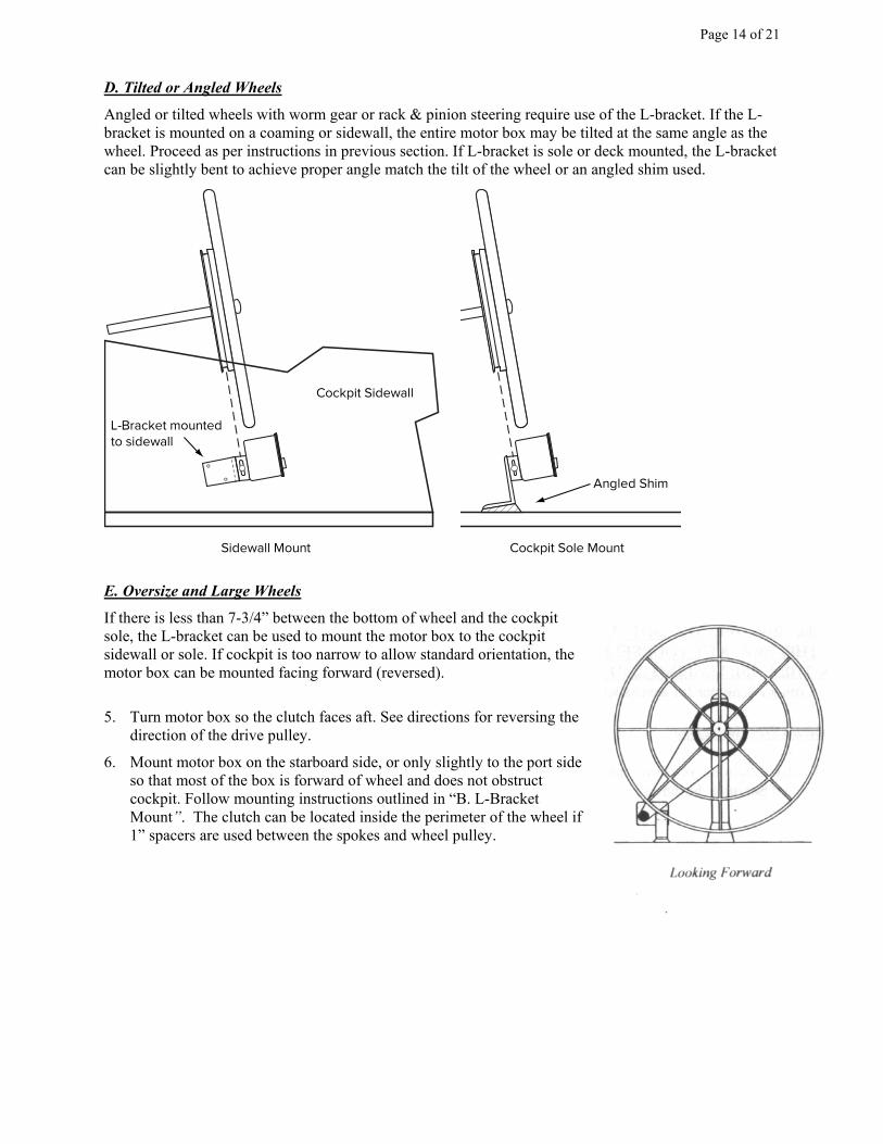
D. Tilted or Angled Wheels
Angled or tilted wheels with worm gear or rack & pinion steering require use of the L-bracket. If the L-
bracket is mounted on a coaming or sidewall, the entire motor box may be tilted at the same angle as the
wheel. Proceed as per instructions in previous section. If L-bracket is sole or deck mounted, the L-bracket
can be slightly bent to achieve proper angle match the tilt of the wheel or an angled shim used.
Angled Shim
Cockpit Sidewall
L-Bracket mounted
to sidewall
Sidewall Mount Cockpit Sole Mount
E. Oversize and Large Wheels
If there is less than 7-3/4” between the bottom of wheel and the cockpit
sole, the L-bracket can be used to mount the motor box to the cockpit
sidewall or sole. If cockpit is too narrow to allow standard orientation, the
motor box can be mounted facing forward (reversed).
5. Turn motor box so the clutch faces aft. See directions for reversing the
direction of the drive pulley.
6. Mount motor box on the starboard side, or only slightly to the port side
so that most of the box is forward of wheel and does not obstruct
cockpit. Follow mounting instructions outlined in “B. L-Bracket
Mount”. The clutch can be located inside the perimeter of the wheel if
1” spacers are used between the spokes and wheel pulley.
Page 15 of 21
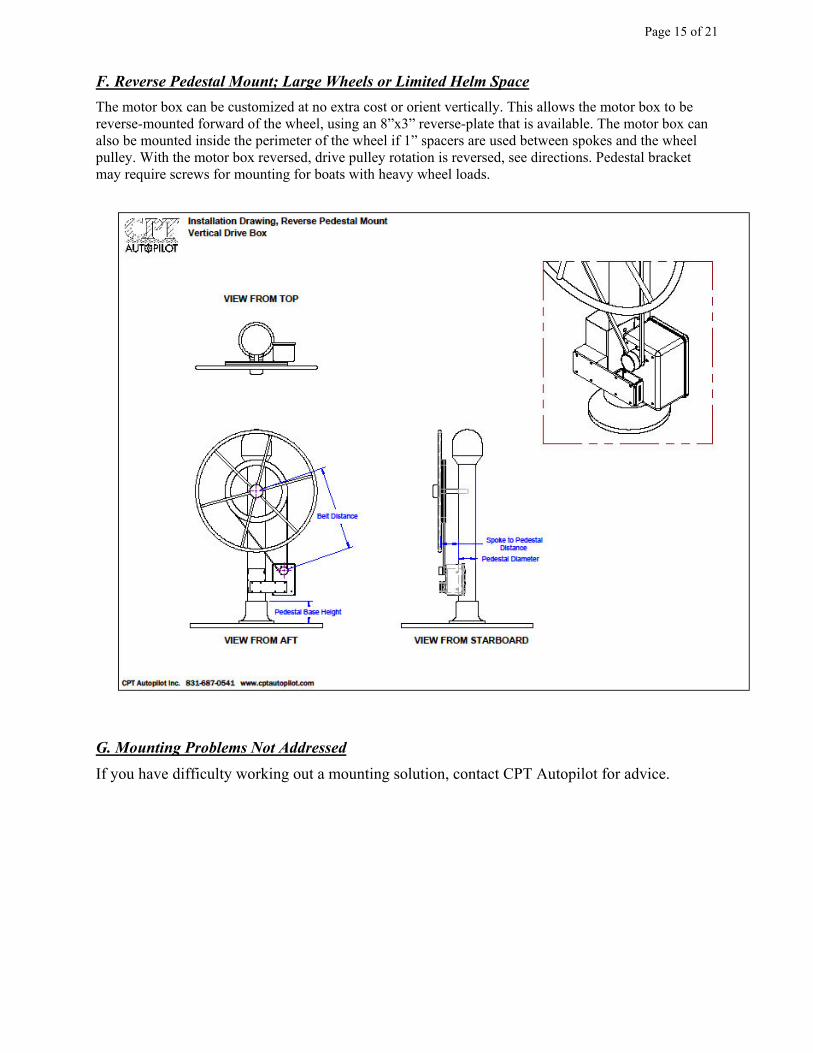
F. Reverse Pedestal Mount; Large Wheels or Limited Helm Space
The motor box can be customized at no extra cost or orient vertically. This allows the motor box to be
reverse-mounted forward of the wheel, using an 8”x3” reverse-plate that is available. The motor box can
also be mounted inside the perimeter of the wheel if 1” spacers are used between spokes and the wheel
pulley. With the motor box reversed, drive pulley rotation is reversed, see directions. Pedestal bracket
may require screws for mounting for boats with heavy wheel loads.
G. Mounting Problems Not Addressed
If you have difficulty working out a mounting solution, contact CPT Autopilot for advice.
Page 16 of 21
6. Electrical Connection
The autopilot is turned On/Off by rotating the rudder-control knob from the off position. Keep
the autopilot turned off when making electrical connections. Connect motor box power line to a
good 12-volt power source with 12ga cable. Even though current draw is low, the CPT will
compensate for voltage drop from small wires by increasing current draw. Be sure to use a good
quality 10-amp circuit-breaker, or attach the 10-amp inline fuse that is supplied. A 10-amp
circuit breaker is recommended to avoid a slight 0.00004 amp draw when the unit is off. If
possible, use a circuit breaker directly from the battery or battery selector switch. If this is not
possible, tie into 12 gauge wire minimum, with the shortest run. Do not tie into the ignition side
of any source. It is important that good solid connections be made. A waterproof connector may
be used on the power line, do not use a push-in or cigarette-lighter type connector. Use a
connector with a screw-down cap and plug, and a compression fitting to seal cable-jacket as it
enters the cap, and tin the wire ends. The cable jacket should always be kept sealed; an open or
damaged jacket can lead to water intrusion. The RED WIRE CONNECTS TO 12V (+). Do not
leave supplied fuse holder out in the weather, it is not waterproof.
Size cable for 3% voltage drop or less. Use 12 AWG 12-2 cable for adding up to 10’ of cable,
use 10 AWG for adding 20’, 8 AWG for adding 30’.
Splicing Control Box Cable:
The control cable is shielded 6-conductor, 24ga color-coded. If wires are cross-connected during
splicing or routing damage may result which is not covered under the warranty. ONLY cut or
splice for routing AFTER SEA TRIALS.
A. Changing the rotation of the wheel & small drive pulley
This has been preset for your installation at the factory and should not need
changing, but can be changed easily:
Standard installations with the drive-pulley facing forward:
Hold down the Starboard 1& 10 degree buttons and the Port 10 degree button at the same time,
hold the three buttons down while turning the pilot on, then release the buttons 5 seconds afterwards.
Test by pusing a 10-degree button.
Reverse-mounting with the drive pulley facing aft:
Hold the Port 1& 10 degree buttons and the Starboard 10 degree button down at the same time,
hold the three buttons down while turning the pilot on, then release the buttons 5 seconds afterwards.
Test by pushing a 10-degree button.
Page 17 of 21
B. Setting the Magnetic Reference; Northern/Southern Hemispheres
The autopilot comes set for the Northern Hemisphere’s magnetic field inclination. If you are located near
the equator, south of the equator or approaching the poles, the Magnetic Reference should be set again on
location.
This procedure is best performed at the dock in flat water. If at sea, only perform this procedure in calm
seas while holding the control box to stabilize it. If the control box is not kept level or is bumped during
this procedure, the reference will be skewed resulting in poor autopilot performance.
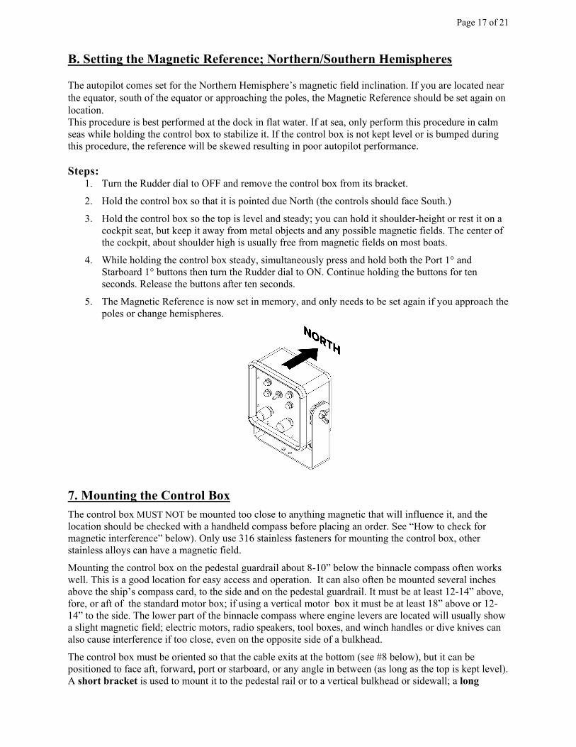
Steps: 1. Turn the Rudder dial to OFF and remove the control box from its bracket.
2. Hold the control box so that it is pointed due North (the controls should face South.)
3. Hold the control box so the top is level and steady; you can hold it shoulder-height or rest it on a
cockpit seat, but keep it away from metal objects and any possible magnetic fields. The center of
the cockpit, about shoulder high is usually free from magnetic fields on most boats.
4. While holding the control box steady, simultaneously press and hold both the Port 1° and
Starboard 1° buttons then turn the Rudder dial to ON. Continue holding the buttons for ten
seconds. Release the buttons after ten seconds.
5. The Magnetic Reference is now set in memory, and only needs to be set again if you approach the
poles or change hemispheres.
7. Mounting the Control Box
The control box MUST NOT be mounted too close to anything magnetic that will influence it, and the
location should be checked with a handheld compass before placing an order. See “How to check for
magnetic interference” below). Only use 316 stainless fasteners for mounting the control box, other
stainless alloys can have a magnetic field.
Mounting the control box on the pedestal guardrail about 8-10” below the binnacle compass often works
well. This is a good location for easy access and operation. It can also often be mounted several inches
above the ship’s compass card, to the side and on the pedestal guardrail. It must be at least 12-14” above,
fore, or aft of the standard motor box; if using a vertical motor box it must be at least 18” above or 12-
14” to the side. The lower part of the binnacle compass where engine levers are located will usually show
a slight magnetic field; electric motors, radio speakers, tool boxes, and winch handles or dive knives can
also cause interference if too close, even on the opposite side of a bulkhead.
The control box must be oriented so that the cable exits at the bottom (see #8 below), but it can be
positioned to face aft, forward, port or starboard, or any angle in between (as long as the top is kept level).
A short bracket is used to mount it to the pedestal rail or to a vertical bulkhead or sidewall; a long
Page 18 of 21
bracket is used to mount it to a horizontal shelf, console, or to hang from an overhead. Only one bracket
is included, let us know which is preferred at time of ordering. Only use 316 stainless fasteners.
A. Control Box Mounting Requirements
Mount the control box a minimum 12 inches above motor box and minimum 8-10” below the
binnacle compass or several inches above it. If mounting the control box to a cockpit sidewall, do
not mount it directly to port or starboard of the motor box, mount it a minimum 12” fore or aft of
the motor box; if using a vertical motor box at least 18” above it or 12” to the side; this to avoid
interference from the motor’s magnetic field. A common cause of magnetic interference is
locating the control box too close to the motor box or close to old engine control cables & parts
that may have become magnetized over the years.
NOTE REGARDING STEEL BOATS:
On steel boats, the control box must be located more than 6-feet from the nearest
steel. Magnetic objects cause attractive and repelling forces to act on the sensor. On
some headings the boat may change heading 5-degrees while the sensor changes 20-
degrees; on other headings the boat may change heading 20-degrees with the sensor
only changing 5- degrees (hanging).
The CPT is able to steer on some steel boats but not all. The electronic sensor in the
control box is more sensitive to magnetic fields than the older CPT models that used
an optical compass. Every steel boat is different, and any magnetic fields cannot
cause more than 5-degrees of needle deflection from a hand-held compass. Some
owners have mounted it on wooden boom gallows, aluminum or wooden
mizzenmasts, under or on top of wooden coach roof, etc. Contact us for directions for
performing a magnetic survey of your vessel before ordering a CPT.
B. Testing the Control Box before final mounting
Before tightening the control box bracket to the pedestal pipe, or drilling pilot holes to mount
the control box bracket on a console/overhead or to a bulkhead, do the following steps:
1. After setting the magnetic reference (see #6-B, Setting the Magnetic Reference), temporarily mount
the control box in its proposed location. Mount the control box in the bracket using the wing nuts,
with rubber washer on the inside. (Only tighten wing-nuts finger tight, never use pliers or the bolts
can break/strip). Keep the top of the control box level; do not tilt out of plumb in the bracket.
2. Slip the belt OFF the small motor pulley gear, and engage clutch. (Push the black pulley gear in
while turning it until it snaps in.)
3. Check to make sure that the 10 amp fuse is in place, and that power is available. The red wire must
connect to 12(+), the black power to 12v. The wheel direction has been preset for your installation at
the factory; you should not have to make any changes.
4. Flip toggle to STANDBY, turn autopilot on by turning Rudder dial ON and set to 5, Deadband dial
to 3, and allow a 1 minute warm-up. (*Do not toggle to Hold-Heading until warm-up is completed)
5. After warm up, flip the toggle to HOLD HEADING. Push the 10-degree PORT button once: the
small drive pulley should turn in the direction needed to turn the boat to port. It will make an initial
rotation, then stop and wait, with repeated short pulses once/second in an attempt to change the
boat’s heading. Push the 10-degree Starboard button once: the small drive pulley should rotate back
in the direction to turn the boat to starboard.
Page 19 of 21
* When left on Hold Heading, it is normal for the pilot to make a small correction once every 10
seconds. If the belt is on DO NOT let the wheel corrections continue until the rudder-stops are
reached, flip to Standby or turn power off or disengage clutch.
6. Tighten the clamp or complete the console or bulkhead mounting after testing the control box.
7. Follow the steps for DOCKSIDE Check-Out and Sea Trials in the OPERATION
MANUAL
C. Troubleshooting
• If the drive pulley is not turning in the proper direction: following the directions for reversing
the wheel rotation in “6. Electrical Connection”.
• If the drive pulley does not turn at all: be sure the clutch is engaged, check for proper wiring
and that the red wire connects to 12v(+). If the power wires are connected wrong there will
be no response from the control box controls or small drive pulley and the pilot will not
operate.
• After 1 minute warm-up if the pilot makes corrections once per second in the same direction
while stationary:
1. Flip the toggle to Standby and then back to Hold Heading
2. Keep the control box steady and observe the drive gear
3. If the autopilot makes corrections once per second in the same direction, flip the toggle to
Standby, wait 30 seconds, and then flip toggle back to Hold Heading
4. If the autopilot continues to make corrections at least once per second in the same
direction as before, this is an indication that:
o the pilot was not allowed adequate warm-up time, or
o the boat’s heading is changing, or
o there is magnetic interference
o the magnetic reference was not set
• Magnetic interference: Try moving the control box further from the motor box or other
magnetic influence, try holding it high above the pedestal, or to a cockpit seat or other area to
temporarily to test the pilot and find a suitable location. Another location for the control box
may have to be found, contact CPT for advice.
• Check the electrical connection by testing Motor torque/voltalge drop: With the belt off and
clutch engaged, set the rudder control to 10 and push a 10-degree button. Grip the clutch disk
with your hand; the motor should show good torque and be difficult to slow. If the clutch is
easily stopped there is voltage drop in the electrical connection and the pilot will not operate
properly. The 12v power must be measured when the motor is operating to test the
connections.

Page 20 of 21
8. How to check for magnetic interference
The CPT heading sensor is built into the control box, so the control box mounting area should be
free from magnetic influences. The helm area of most boats will be free of magnet fields, but this
should be checked; use a hand-held compass, preferably a needle-bearing hiking compass to
check for magnetic fields near your pedestal. (using magnets to see if they stick to something
magnetic is not useful here at all) Stereo speakers, dive knives, and winch handles should not be
located near the control box, as well as high current cables, radar or large LCD screens. Stainless
fittings that are not 316 stainless can be magnetic, and pedestal guardrails made from dodger
fittings are often susceptible.
There is a short video on our website that demonstrates how to check for magnetic interference:
http://cptautopilot.com/magnetic_interference_check.php
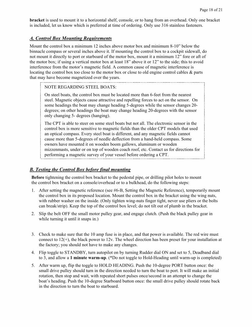
A handheld compass that uses a needle (a simple hiking compass) is usually more accurate and
easier to use than one that uses a floating card. If using a marine handheld compass with a
floating card, it helps to apply a thin piece of tape as a marker on the face. Most handhelds have
only 5-degree markings; a thin slice of tape as a reference can make reading card movement
easier.
With your boat parallel to the dock, check the heading of the dock and boat’s heading with the
magnetic compass; then step on the boat, hold the compass 3' above or away from the pedestal
and take a reading. The two headings should be very close. Keeping the compass oriented,
approach the pedestal area and watch the needle to notice any deflection from magnetic fields.
Next place a yardstick or a firm wooden straight-edge against the pedestal guardrail and rest it
firmly on the deck. Hold the straight-edge steady, so it doesn’t twist. While holding the compass
firmly against the straight-edge to keep the compass from rotating at all, slowly slide it up and
down the straight edge and notice the amount of needle movement or deflection. The needle
must not be pulled or deflected more than 5-degrees near the mounting area.
Page 21 of 21
You may notice some needle deflection as you pass the area just next to the ship’s compass (there are
compensating magnets in the case) and near the engine control levers. There is usually no needle
deflection 6-10” below this area or 3" - 4" above the ship’s compass card. If the needle deflects more than
5°, a more suitable location will need to be found for the control box.
Some boats may have steel parts that have become magnetized over the years. Magnetism can come from
steel in engine control cables and pins, steering cable fittings, any stainless bolts or dodger fittings that are
not 316 ss, homemade guardrails, and fasteners used for pedestal tables. Welded joints or parts may also
be magnetic. On a few boats, the boat’s engine is located just inches under the pedestal which may cause
a problem. Steel boats should do a careful magnetic survey, and have a mounting location at least 6 ft
from the nearest steel plates.
If a suitable location is not available for the control box, use of the CPT is not recommended.
Apply a thin slice of tape as a marker on
the face of the handheld compass. This will
provide a reference that makes reading the
compass card movement easier.
1. Hold the compass edge firmly against
the straight edge to keep compass
oriented without movement or rotation.
2. Take readings from the deck level to
above the pedestal, next to each guard
rail. Repeat the readings forward and
aft of each guardrail.
3. Compass needle deflection should not
be more than 5 degrees.