Embed Size (px)
Citation preview
Aluminum Electrolytic Capacitors: SMD
Series/Type: B41121
The following products presented in this data sheet are being withdrawn.
Ordering Code Substitute Product Date ofWithdrawal
Deadline LastOrders
Last Shipments
B41121* 2013-02-22 2013-09-30 2014-03-31
For further information please contact your nearest EPCOS sales office, which will also supportyou in selecting a suitable substitute. The addresses of our worldwide sales network arepresented at www.epcos.com/sales.
© EPCOS AG 2015. Reproduction, publication and dissemination of this publication, enclosures hereto and the information contained therein without EPCOS' prior express consent is prohibited.
EPCOS AG is a TDK Group Company.
SMD capacitors B41121Standard series – 105 °C
2 08/08Please read Cautions and warnings and Important notes at the end of this document.
SMD capacitors B41121Standard series – 105 °CGeneral-purpose grade capacitors
Applications
■ For general-purpose applications in the entertainment industry
Features
■ Miniaturized dimensions■ RoHS-compatible■ Load life of 1000 h at 105 °C
Construction
■ Surface mounting device■ Minus pole marking on the case
Delivery mode
■ Taped and reeled
Specifications and characteristics in brief
Rated voltage VR 4 … 50 V DCOperating temperature range –40 °C … +105 °CRated capacitance CR(20 °C, 120 Hz)
0.1 … 1000 µF
Capacitance tolerance ±20% MLoad life(105 °C, VR)
1000 h Requirements:∆C/C ≤ ±20% of initial value
(≤ 16 V: within ±25% of the initial value)tan δ ≤ 2 times initial specified limitIleak ≤ initial specified limit
Leakage current Ileak(20 °C, after 2 minutes)
Low temperature stability(impedance ratio)(120 Hz)
VR (V DC) 4 6.3 10 16 25 35 507 4 3 2 2 2 2
15 8 6 4 4 3 3
Shelf life After storage for 1000 h at 105 °C, the capacitors shall meet the requirement of load life test after reforming process. After test: VR to be applied for 30 minutes, 24 to 48 hours before measurement.
Frequency multiplierfor rated ripple current
50 Hz 120 Hz 300 Hz 1 kHz ≥10 kHz0.70 1.00 1.17 1.36 1.50
Ileak 0.01 µACRµF-------
VRV
-------⋅⎝ ⎠⎛ ⎞ or 3 µA, whichever is greater⋅≤
Z 25 °C–( )Z +20 °C( )---------------------------
Z 40 °C–( )Z +20 °C( )---------------------------
SMD capacitors B41121Standard series – 105 °C
3 08/08Please read Cautions and warnings and Important notes at the end of this document.
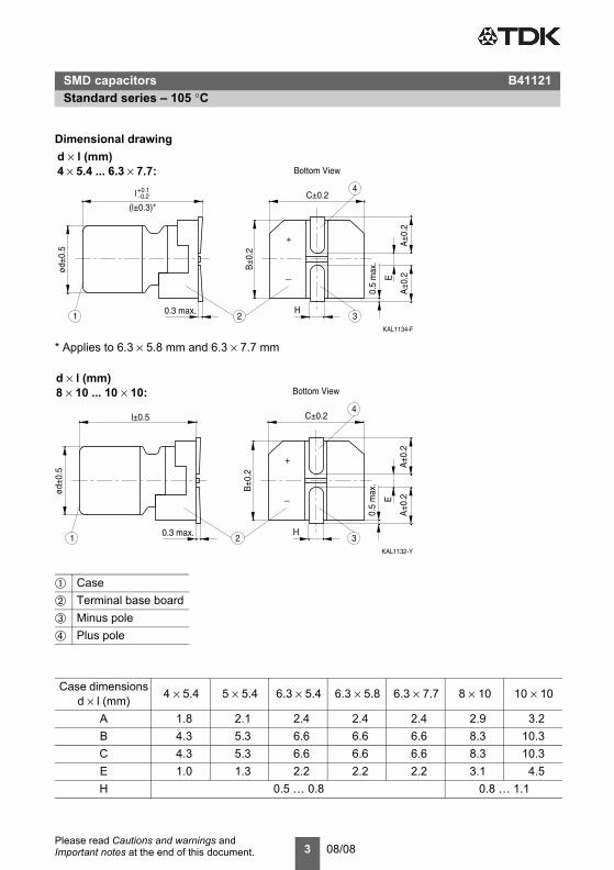
Dimensional drawing
* Applies to 6.3 × 5.8 mm and 6.3 × 7.7 mm
➀ Case➁ Terminal base board➂ Minus pole➃ Plus pole
Case dimensionsd × l (mm) 4 × 5.4 5 × 5.4 6.3 × 5.4 6.3 × 5.8 6.3 × 7.7 8 × 10 10 × 10
A 1.8 2.1 2.4 2.4 2.4 2.9 3.2B 4.3 5.3 6.6 6.6 6.6 8.3 10.3C 4.3 5.3 6.6 6.6 6.6 8.3 10.3E 1.0 1.3 2.2 2.2 2.2 3.1 4.5H 0.5 … 0.8 0.8 … 1.1
KAL1134-F
0.3 max.
ød±0
.5
C±0.2
B±0
.2
H
E
+
_
A±0
.2
1 2 3
4
0.5
max
.
A±0
.2
Bottom View
_+0.1l 0.2
(l±0.3)*
d × l (mm)4 × 5.4 ... 6.3 × 7.7:
KAL1132-Y
l±0.5
0.3 max.
ød±0
.5
C±0.2
B±0
.2
H
E
+
_
A±0
.2
1 2 3
4
0.5
max
.
A±0
.2Bottom View
d × l (mm)8 × 10 ... 10 × 10:
SMD capacitors B41121Standard series – 105 °C
4 08/08Please read Cautions and warnings and Important notes at the end of this document.
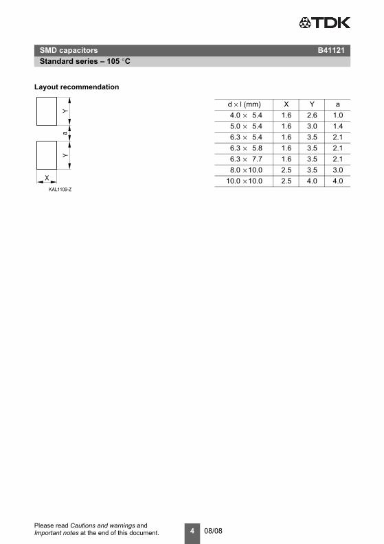
Layout recommendation
KAL1109-Z
YY
a
X
d × l (mm) X Y a4.0 × 5.4 1.6 2.6 1.05.0 × 5.4 1.6 3.0 1.46.3 × 5.4 1.6 3.5 2.16.3 × 5.8 1.6 3.5 2.16.3 × 7.7 1.6 3.5 2.18.0 × 10.0 2.5 3.5 3.0
10.0 × 10.0 2.5 4.0 4.0
SMD capacitors B41121Standard series – 105 °C
5 08/08Please read Cautions and warnings and Important notes at the end of this document.
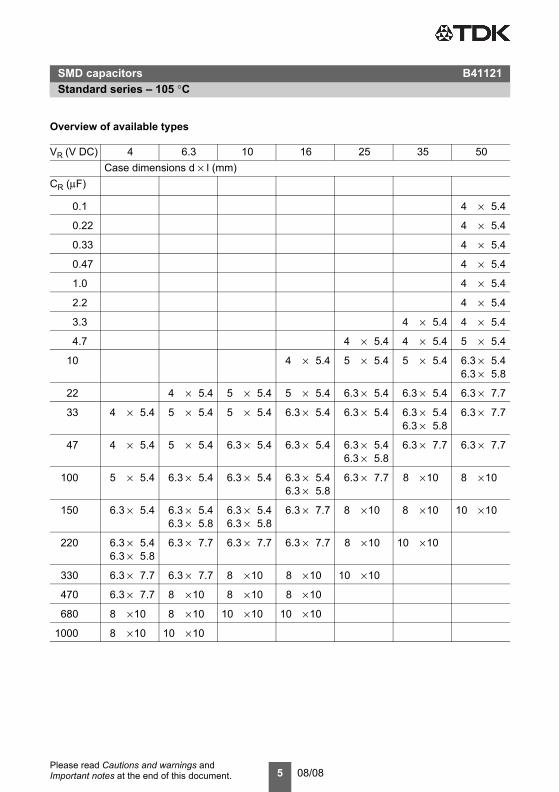
Overview of available types
VR (V DC) 4 6.3 10 16 25 35 50Case dimensions d × l (mm)
CR (µF)
0.1 4 × 5.4
0.22 4 × 5.4
0.33 4 × 5.4
0.47 4 × 5.4
1.0 4 × 5.4
2.2 4 × 5.4
3.3 4 × 5.4 4 × 5.4
4.7 4 × 5.4 4 × 5.4 5 × 5.4
10 4 × 5.4 5 × 5.4 5 × 5.4 6.3 × 5.46.3 × 5.8
22 4 × 5.4 5 × 5.4 5 × 5.4 6.3 × 5.4 6.3 × 5.4 6.3 × 7.7
33 4 × 5.4 5 × 5.4 5 × 5.4 6.3 × 5.4 6.3 × 5.4 6.3 × 5.46.3 × 5.8
6.3 × 7.7
47 4 × 5.4 5 × 5.4 6.3 × 5.4 6.3 × 5.4 6.3 × 5.46.3 × 5.8
6.3 × 7.7 6.3 × 7.7
100 5 × 5.4 6.3 × 5.4 6.3 × 5.4 6.3 × 5.46.3 × 5.8
6.3 × 7.7 8 ×10 8 ×10
150 6.3 × 5.4 6.3 × 5.46.3 × 5.8
6.3 × 5.46.3 × 5.8
6.3 × 7.7 8 ×10 8 ×10 10 ×10
220 6.3 × 5.46.3 × 5.8
6.3 × 7.7 6.3 × 7.7 6.3 × 7.7 8 ×10 10 ×10
330 6.3 × 7.7 6.3 × 7.7 8 ×10 8 ×10 10 ×10
470 6.3 × 7.7 8 ×10 8 ×10 8 ×10
680 8 ×10 8 ×10 10 ×10 10 ×10
1000 8 ×10 10 ×10
SMD capacitors B41121Standard series – 105 °C
6 08/08Please read Cautions and warnings and Important notes at the end of this document.
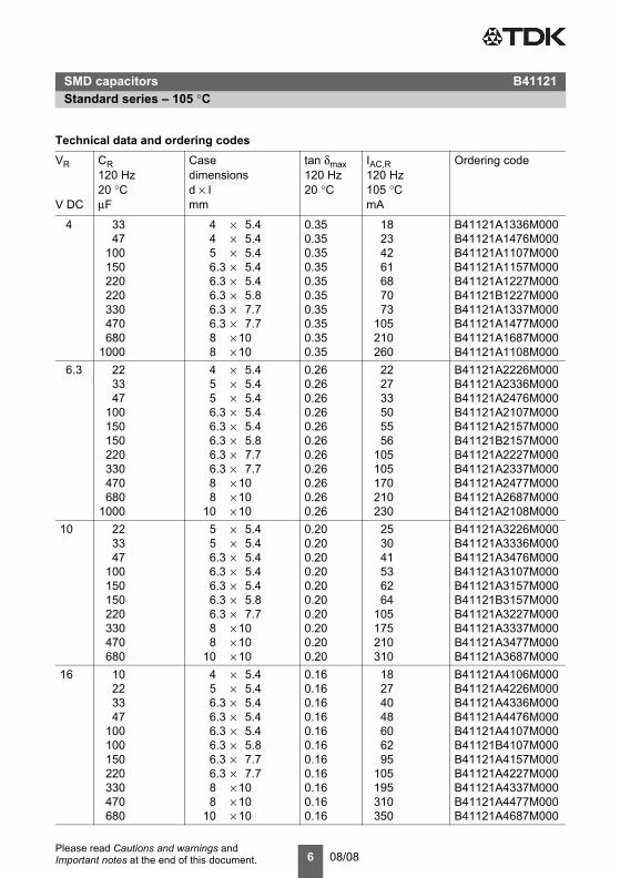
Technical data and ordering codesVR
V DC
CR120 Hz20 °CµF
Case dimensionsd × lmm
tan δmax120 Hz20 °C
IAC,R120 Hz105 °CmA
Ordering code
4 33 4 × 5.4 0.35 18 B41121A1336M00047 4 × 5.4 0.35 23 B41121A1476M000
100 5 × 5.4 0.35 42 B41121A1107M000150 6.3 × 5.4 0.35 61 B41121A1157M000220 6.3 × 5.4 0.35 68 B41121A1227M000220 6.3 × 5.8 0.35 70 B41121B1227M000330 6.3 × 7.7 0.35 73 B41121A1337M000470 6.3 × 7.7 0.35 105 B41121A1477M000680 8 × 10 0.35 210 B41121A1687M000
1000 8 × 10 0.35 260 B41121A1108M0006.3 22 4 × 5.4 0.26 22 B41121A2226M000
33 5 × 5.4 0.26 27 B41121A2336M00047 5 × 5.4 0.26 33 B41121A2476M000
100 6.3 × 5.4 0.26 50 B41121A2107M000150 6.3 × 5.4 0.26 55 B41121A2157M000150 6.3 × 5.8 0.26 56 B41121B2157M000220 6.3 × 7.7 0.26 105 B41121A2227M000330 6.3 × 7.7 0.26 105 B41121A2337M000470 8 × 10 0.26 170 B41121A2477M000680 8 × 10 0.26 210 B41121A2687M000
1000 10 × 10 0.26 230 B41121A2108M00010 22 5 × 5.4 0.20 25 B41121A3226M000
33 5 × 5.4 0.20 30 B41121A3336M00047 6.3 × 5.4 0.20 41 B41121A3476M000
100 6.3 × 5.4 0.20 53 B41121A3107M000150 6.3 × 5.4 0.20 62 B41121A3157M000150 6.3 × 5.8 0.20 64 B41121B3157M000220 6.3 × 7.7 0.20 105 B41121A3227M000330 8 × 10 0.20 175 B41121A3337M000470 8 × 10 0.20 210 B41121A3477M000680 10 × 10 0.20 310 B41121A3687M000
16 10 4 × 5.4 0.16 18 B41121A4106M00022 5 × 5.4 0.16 27 B41121A4226M00033 6.3 × 5.4 0.16 40 B41121A4336M00047 6.3 × 5.4 0.16 48 B41121A4476M000
100 6.3 × 5.4 0.16 60 B41121A4107M000100 6.3 × 5.8 0.16 62 B41121B4107M000150 6.3 × 7.7 0.16 95 B41121A4157M000220 6.3 × 7.7 0.16 105 B41121A4227M000330 8 × 10 0.16 195 B41121A4337M000470 8 × 10 0.16 310 B41121A4477M000680 10 × 10 0.16 350 B41121A4687M000
SMD capacitors B41121Standard series – 105 °C
7 08/08Please read Cautions and warnings and Important notes at the end of this document.
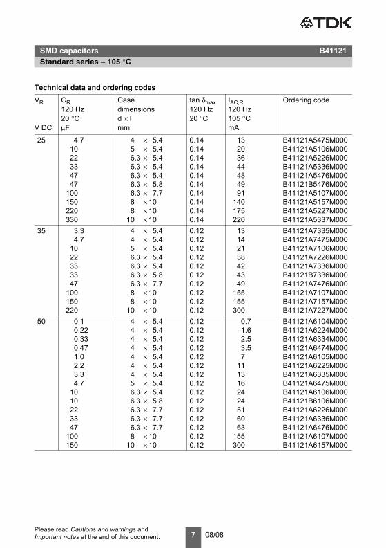
25 4.7 4 × 5.4 0.14 13 B41121A5475M00010 5 × 5.4 0.14 20 B41121A5106M00022 6.3 × 5.4 0.14 36 B41121A5226M00033 6.3 × 5.4 0.14 44 B41121A5336M00047 6.3 × 5.4 0.14 48 B41121A5476M00047 6.3 × 5.8 0.14 49 B41121B5476M000
100 6.3 × 7.7 0.14 91 B41121A5107M000150 8 × 10 0.14 140 B41121A5157M000220 8 × 10 0.14 175 B41121A5227M000330 10 × 10 0.14 220 B41121A5337M000
35 3.3 4 × 5.4 0.12 13 B41121A7335M0004.7 4 × 5.4 0.12 14 B41121A7475M000
10 5 × 5.4 0.12 21 B41121A7106M00022 6.3 × 5.4 0.12 38 B41121A7226M00033 6.3 × 5.4 0.12 42 B41121A7336M00033 6.3 × 5.8 0.12 43 B41121B7336M00047 6.3 × 7.7 0.12 49 B41121A7476M000
100 8 × 10 0.12 155 B41121A7107M000150 8 × 10 0.12 155 B41121A7157M000220 10 × 10 0.12 300 B41121A7227M000
50 0.1 4 × 5.4 0.12 0.7 B41121A6104M0000.22 4 × 5.4 0.12 1.6 B41121A6224M0000.33 4 × 5.4 0.12 2.5 B41121A6334M0000.47 4 × 5.4 0.12 3.5 B41121A6474M0001.0 4 × 5.4 0.12 7 B41121A6105M0002.2 4 × 5.4 0.12 11 B41121A6225M0003.3 4 × 5.4 0.12 13 B41121A6335M0004.7 5 × 5.4 0.12 16 B41121A6475M000
10 6.3 × 5.4 0.12 24 B41121A6106M00010 6.3 × 5.8 0.12 24 B41121B6106M00022 6.3 × 7.7 0.12 51 B41121A6226M00033 6.3 × 7.7 0.12 60 B41121A6336M00047 6.3 × 7.7 0.12 63 B41121A6476M000
100 8 × 10 0.12 155 B41121A6107M000150 10 × 10 0.12 300 B41121A6157M000
Technical data and ordering codesVR
V DC
CR120 Hz20 °CµF
Case dimensionsd × lmm
tan δmax120 Hz20 °C
IAC,R120 Hz105 °CmA
Ordering code
SMD capacitors B41121Mounting intructions
8 08/08Please read Cautions and warnings and Important notes at the end of this document.
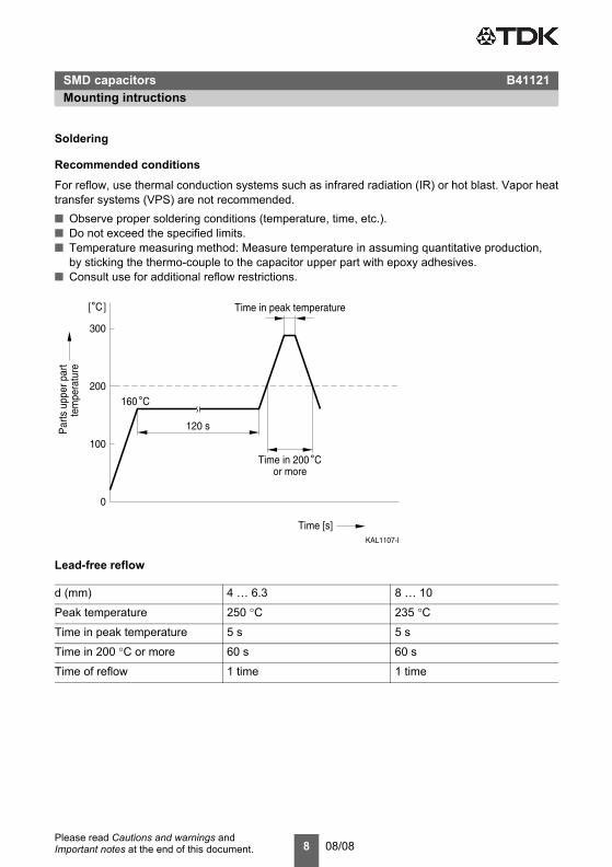
Soldering
Recommended conditions
For reflow, use thermal conduction systems such as infrared radiation (IR) or hot blast. Vapor heattransfer systems (VPS) are not recommended.■ Observe proper soldering conditions (temperature, time, etc.).■ Do not exceed the specified limits.■ Temperature measuring method: Measure temperature in assuming quantitative production,
by sticking the thermo-couple to the capacitor upper part with epoxy adhesives.■ Consult use for additional reflow restrictions.
Lead-free reflow
d (mm) 4 … 6.3 8 … 10
Peak temperature 250 °C 235 °C
Time in peak temperature 5 s 5 s
Time in 200 °C or more 60 s 60 s
Time of reflow 1 time 1 time
KAL1107-I
0
Time [s]
Par
ts u
pper
par
tte
mpe
ratu
re
100
200
300
C˚
120 s
Time in peak temperature
Time in 200˚Cor more
˚160 C
][
SMD capacitors B41121Mounting intructions
SMD capacitors B41121Taping and packing
9 08/08Please read Cautions and warnings and Important notes at the end of this document.
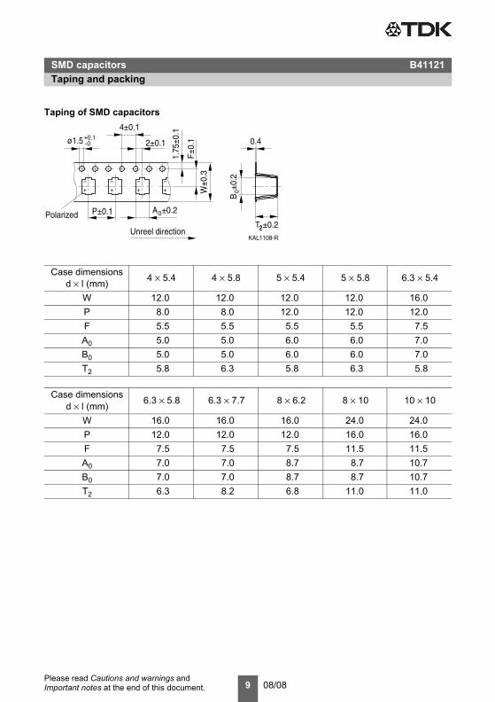
SMD capacitors B41121Taping and packingTaping of SMD capacitors
Taping and packingCase dimensions
d × l (mm) 4 × 5.4 4 × 5.8 5 × 5.4 5 × 5.8 6.3 × 5.4
W 12.0 12.0 12.0 12.0 16.0P 8.0 8.0 12.0 12.0 12.0F 5.5 5.5 5.5 5.5 7.5A0 5.0 5.0 6.0 6.0 7.0B0 5.0 5.0 6.0 6.0 7.0T2 5.8 6.3 5.8 6.3 5.8
Case dimensionsd × l (mm) 6.3 × 5.8 6.3 × 7.7 8 × 6.2 8 × 10 10 × 10
W 16.0 16.0 16.0 24.0 24.0P 12.0 12.0 12.0 16.0 16.0F 7.5 7.5 7.5 11.5 11.5A0 7.0 7.0 8.7 8.7 10.7B0 7.0 7.0 8.7 8.7 10.7T2 6.3 8.2 6.8 11.0 11.0
KAL1108-R
2±0.1
4±0.1
1.75
±0.1
A0
ø1.5 0+0.1_
_+
Polarized
_+
_+
_+
P±0.1 ±0.2
F±0.
1
W±0
.3
±0.22±0
.2B
0
0.4
Unreel direction 2T
SMD capacitors B41121Taping and packing
10 08/08Please read Cautions and warnings and Important notes at the end of this document.
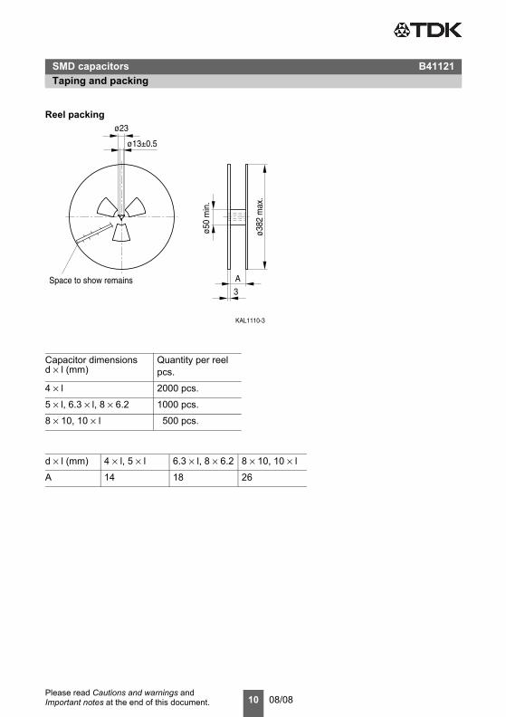
Reel packing
Capacitor dimensionsd × l (mm)
Quantity per reelpcs.
4 × l 2000 pcs.
5 × l, 6.3 × l, 8 × 6.2 1000 pcs.
8 × 10, 10 × l 500 pcs.
d × l (mm) 4 × l, 5 × l 6.3 × l, 8 × 6.2 8 × 10, 10 × l
A 14 18 26
KAL1110-3
ø23
ø50
min
.
A
ø13±0.5
3Space to show remains
ø382
max
.
11 08/08Please read Cautions and warnings and Important notes at the end of this document.
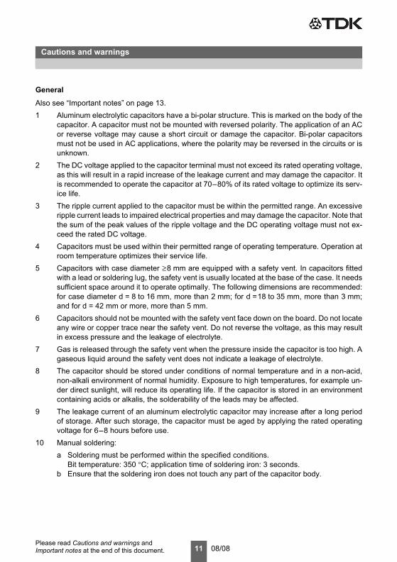
General
Also see “Important notes” on page 13.1 Aluminum electrolytic capacitors have a bi-polar structure. This is marked on the body of the
capacitor. A capacitor must not be mounted with reversed polarity. The application of an ACor reverse voltage may cause a short circuit or damage the capacitor. Bi-polar capacitorsmust not be used in AC applications, where the polarity may be reversed in the circuits or isunknown.
2 The DC voltage applied to the capacitor terminal must not exceed its rated operating voltage,as this will result in a rapid increase of the leakage current and may damage the capacitor. Itis recommended to operate the capacitor at 70–80% of its rated voltage to optimize its serv-ice life.
3 The ripple current applied to the capacitor must be within the permitted range. An excessiveripple current leads to impaired electrical properties and may damage the capacitor. Note thatthe sum of the peak values of the ripple voltage and the DC operating voltage must not ex-ceed the rated DC voltage.
4 Capacitors must be used within their permitted range of operating temperature. Operation atroom temperature optimizes their service life.
5 Capacitors with case diameter ≥8 mm are equipped with a safety vent. In capacitors fittedwith a lead or soldering lug, the safety vent is usually located at the base of the case. It needssufficient space around it to operate optimally. The following dimensions are recommended:for case diameter d = 8 to 16 mm, more than 2 mm; for d =18 to 35 mm, more than 3 mm;and for d = 42 mm or more, more than 5 mm.
6 Capacitors should not be mounted with the safety vent face down on the board. Do not locateany wire or copper trace near the safety vent. Do not reverse the voltage, as this may resultin excess pressure and the leakage of electrolyte.
7 Gas is released through the safety vent when the pressure inside the capacitor is too high. Agaseous liquid around the safety vent does not indicate a leakage of electrolyte.
8 The capacitor should be stored under conditions of normal temperature and in a non-acid,non-alkali environment of normal humidity. Exposure to high temperatures, for example un-der direct sunlight, will reduce its operating life. If the capacitor is stored in an environmentcontaining acids or alkalis, the solderability of the leads may be affected.
9 The leakage current of an aluminum electrolytic capacitor may increase after a long periodof storage. After such storage, the capacitor must be aged by applying the rated operatingvoltage for 6–8 hours before use.
10 Manual soldering:a Soldering must be performed within the specified conditions.
Bit temperature: 350 °C; application time of soldering iron: 3 seconds.b Ensure that the soldering iron does not touch any part of the capacitor body.
Cautions and warnings
Cautions and warnings
12 08/08Please read Cautions and warnings and Important notes at the end of this document.
11 Do not apply excessive force to the leads and terminals. Do not move the capacitor after sol-dering it onto the PC board and do not carry the PC board by gripping the capacitor. Observethe following rules to prevent undue stress to the capacitor:a Do not tilt or bend the capacitor after soldering.b Ensure that the terminal spacing matches the corresponding hole spacing on the PC
board.12 The aluminum case is not insulated from the cathode. Do not place a conductor under the
aluminum capacitors on the PC board as this may cause a short circuit. The case and top ofcapacitors used in switched mode power supplies have a high-voltage-resistant heat shrinksleeve to ensure safe usage.
13 The leads of capacitors with a case diameter exceeding 14 mm cannot be used for fixing.
13 08/08
Important notes
The following applies to all products named in this publication:
1. Some parts of this publication contain statements about the suitability of our products for certain areas of application. These statements are based on our knowledge of typical requirements that are often placed on our products in the areas of application concerned. We nevertheless expressly point out that such statements cannot be regarded as binding statements about the suitability of our products for a particular customer application. As a rule we are either unfamiliar with individual customer applications or less familiar with them than the customers themselves. For these reasons, it is always ultimately incumbent on the customer to check and decide whether a product with the properties described in the product specification is suitable for use in a particular customer application.
2. We also point out that in individual cases, a malfunction of electronic components or failure before the end of their usual service life cannot be completely ruled out in the current state of the art, even if they are operated as specified. In customer applications requiring a very high level of operational safety and especially in customer applications in which the malfunction or failure of an electronic component could endanger human life or health (e.g. in accident prevention or life-saving systems), it must therefore be ensured by means of suitable design of the customer application or other action taken by the customer (e.g. installation of protective circuitry or redundancy) that no injury or damage is sustained by third parties in the event of malfunction or failure of an electronic component.
3. The warnings, cautions and product-specific notes must be observed.
4. In order to satisfy certain technical requirements, some of the products described in this publication may contain substances subject to restrictions in certain jurisdictions (e.g. because they are classed as hazardous). Useful information on this will be found in our Material Data Sheets on the Internet (www.tdk-electronics.tdk.com/material). Should you have any more detailed questions, please contact our sales offices.
5. We constantly strive to improve our products. Consequently, the products described in this publication may change from time to time. The same is true of the corresponding product specifications. Please check therefore to what extent product descriptions and specifications contained in this publication are still applicable before or when you place an order.
We also reserve the right to discontinue production and delivery of products. Consequently, we cannot guarantee that all products named in this publication will always be available. The aforementioned does not apply in the case of individual agreements deviating from the foregoing for customer-specific products.
6. Unless otherwise agreed in individual contracts, all orders are subject to our General Terms and Conditions of Supply.
7. Our manufacturing sites serving the automotive business apply the IATF 16949 standard. The IATF certifications confirm our compliance with requirements regarding the quality management system in the automotive industry. Referring to customer requirements and customer specific requirements (“CSR”) TDK always has and will continue to have the policy of respecting individual agreements. Even if IATF 16949 may appear to support the acceptance of unilateral requirements, we hereby like to emphasize that only requirements mutually agreed upon can and will be implemented in our Quality Management System. For clarification purposes we like to point out that obligations from IATF 16949 shall only become legally binding if individually agreed upon.
8. The trade names EPCOS, CeraCharge, CeraDiode, CeraLink, CeraPad, CeraPlas, CSMP, CTVS, DeltaCap, DigiSiMic, ExoCore, FilterCap, FormFit, LeaXield, MiniBlue, MiniCell, MKD, MKK, MotorCap, PCC, PhaseCap, PhaseCube, PhaseMod, PhiCap, PowerHap, PQSine, PQvar, SIFERRIT, SIFI, SIKOREL, SilverCap, SIMDAD, SiMic, SIMID, SineFormer, SIOV, ThermoFuse, WindCap are trademarks registered or pending in Europe and in other countries. Further information will be found on the Internet at www.tdk-electronics.tdk.com/trademarks.
Release 2018-10