Embed Size (px)
Citation preview
Aluminium and Steel Systems
Operating InstructionsPush-button interface
Doc. No. 10000430005_01
Doc
. No.
100
0043
0005
_01
Prin
ted
in G
erm
any
We
rese
rve
the
right
to m
ake
tech
nica
l cha
nges
and
to c
orre
ct e
rror
s. A
ll ill
ustra
tions
are
sim
ilar.
en
Technical Information
Schücoen Operating Instructions Push-button interface 2
Doc. No. 10000430005_01
00 Operating instructions en
Schüco enOperating Instructions Push-button interface 3
Doc. No. 10000430005_01
Contents
4 1. Notes on this document 4 1.1. Target groups and qualifications 4 1.2. Handover of the document 4 1.3. Retention of the document
5 2. SecuritySicherheit 5 2.1. About the safety instructions 5 2.2. Laws, regulations and technical rules 6 2.3. Proper use 6 2.4. General safety instructions
7 3. Contents of delivery, transportation and storage 7 3.1. Contents of delivery 7 3.2. Transportation and storage
8 4. Product description 8 4.1. Set-up and operation 9 4.2. DIP switches 9 4.3. Status LED 10 4.4. Technical data
10 5. Assembly and installation10 5.1. Prerequisites for installation/assembly 11 5.2. Installation11 5.3. Electrical connection
12 6. Decommissioning and disposal
12 7. Service and support
Schücoen Operating Instructions Push-button interface 4
Doc. No. 10000430005_01
1. Notes on this document
1.1. Target groups and qualifications
This document is intended for specialists, such as trained fitters and electricians. Before installing and commissioning, read through this document thoroughly and adhere to the specified sequence of the instructions. Schüco International KG shall not be liable for any damage which arises from a failure to adhere to these instructions.
Qualified personnel means employees who know how to assemble, install, commission, test and operate the product and who have the relevant qualifications, e.g. who have been trained and instructed in accordance with safety regulations on the maintenance and use of appropriate safety equipment and who have received training in First Aid.
Experts are people whose training and experience means that they have sufficient knowledge of power-operated windows, doors and gates and the corresponding electrical installations. They are familiar with the relevant accident prevention regulations, government “safety at work” regulations, guidelines and generally recognised technical regulations so that they are qualified to judge the occupational safety of power-operated windows, doors and gates and the corresponding electrical installations.
1.2. Handover of the document
After commissioning, hand over all the documentation pertaining to this product to the end customer. Make them aware of the safety instructions, to which they must pay particular attention.
1.3. Retention of the document
This document is a component of the product. Keep this document in an accessible place even after installation and commissioning, so that the information is always available.
Schüco enOperating Instructions Push-button interface 5
Doc. No. 10000430005_01
2. SecuritySicherheit
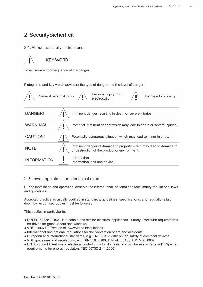
2.1. About the safety instructions
KEY WORD
Type / source / consequence of the danger
Pictograms and key words advise of the type of danger and the level of danger:
General personal injury Personal injury from electrocution Damage to property
DANGER! Imminent danger resulting in death or severe injuries.
WARNING! Potential imminent danger which may lead to death or severe injuries.
CAUTION! Potentially dangerous situation which may lead to minor injuries.
NOTE Imminent danger of damage to property which may lead to damage to or destruction of the product or environment.
INFORMATION InformationInformation, tips and advice
2.2. Laws, regulations and technical rules
During installation and operation, observe the international, national and local safety regulations, laws and guidelines.
Accepted practice as usually codified in standards, guidelines, specifications, and regulations laid down by recognised bodies must be followed.
This applies in particular to:
● DIN EN 60335-2-103 - Household and similar electrical appliances - Safety: Particular requirements for drives for gates, doors and windows ● VDE 100-600: Erection of low-voltage installations ● International and national regulations for the prevention of fire and accidents ● European and international standards, e.g. EN 60335-2-103 on the safety of electrical devices ● VDE guidelines and regulations, e.g. DIN VDE 0100, DIN VDE 0160, DIN VDE 0632 ● EN 60730-2-11: Automatic electrical control units for domestic and similar use – Parts 2-11: Special requirements for energy regulators (IEC 60730-2-11:2006)
Schücoen Operating Instructions Push-button interface 6
Doc. No. 10000430005_01
2.3. Proper use
The device is designed for fixed installations in dry rooms. It must be installed on a standardised profile track (DIN mounting rail, 35 mm) in the distributor or control cabinet.
Proper use also includes adhering to the installation and operating instructions. Any alternative use or a use beyond this remit is not in accordance with its purpose.
Incorrect use or unauthorised modification of the product may result in death or serious injury, or damage to the product and other material assets. Only original replacement parts may be used. The manufacturer / supplier shall not be liable for any damage resulting from infringement. The user alone bears the risk.
This device may be used by children aged 8 and over as well as by persons with reduced physical, sensory or mental capabilities or a lack of experience and knowledge provided that they are supervised or have been instructed in the safe use of the device and understand the resulting dangers. Children must not play with the device. Cleaning and user maintenance must not be carried out by children without supervision. Children should be supervised to ensure that they do not play with the device.
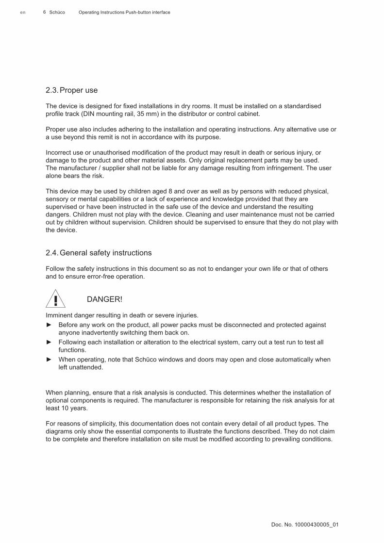
2.4. General safety instructions
Follow the safety instructions in this document so as not to endanger your own life or that of others and to ensure error-free operation.
DANGER!
Imminent danger resulting in death or severe injuries. ► Before any work on the product, all power packs must be disconnected and protected against
anyone inadvertently switching them back on. ► Following each installation or alteration to the electrical system, carry out a test run to test all
functions. ► When operating, note that Schüco windows and doors may open and close automatically when
left unattended.
When planning, ensure that a risk analysis is conducted. This determines whether the installation of optional components is required. The manufacturer is responsible for retaining the risk analysis for at least 10 years.
For reasons of simplicity, this documentation does not contain every detail of all product types. The diagrams only show the essential components to illustrate the functions described. They do not claim to be complete and therefore installation on site must be modified according to prevailing conditions.
Schüco enOperating Instructions Push-button interface 7
Doc. No. 10000430005_01
3. Contents of delivery, transportation and storage
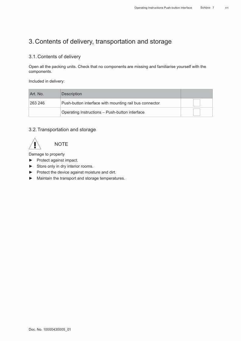
3.1. Contents of delivery
Open all the packing units. Check that no components are missing and familiarise yourself with the components.
Included in delivery:
Art. No. Description
263 246 Push-button interface with mounting rail bus connector
Operating Instructions – Push-button interface
3.2. Transportation and storage
NOTE
Damage to property ► Protect against impact. ► Store only in dry interior rooms. ► Protect the device against moisture and dirt. ► Maintain the transport and storage temperatures.
Schücoen Operating Instructions Push-button interface 8
Doc. No. 10000430005_01
4. Product description
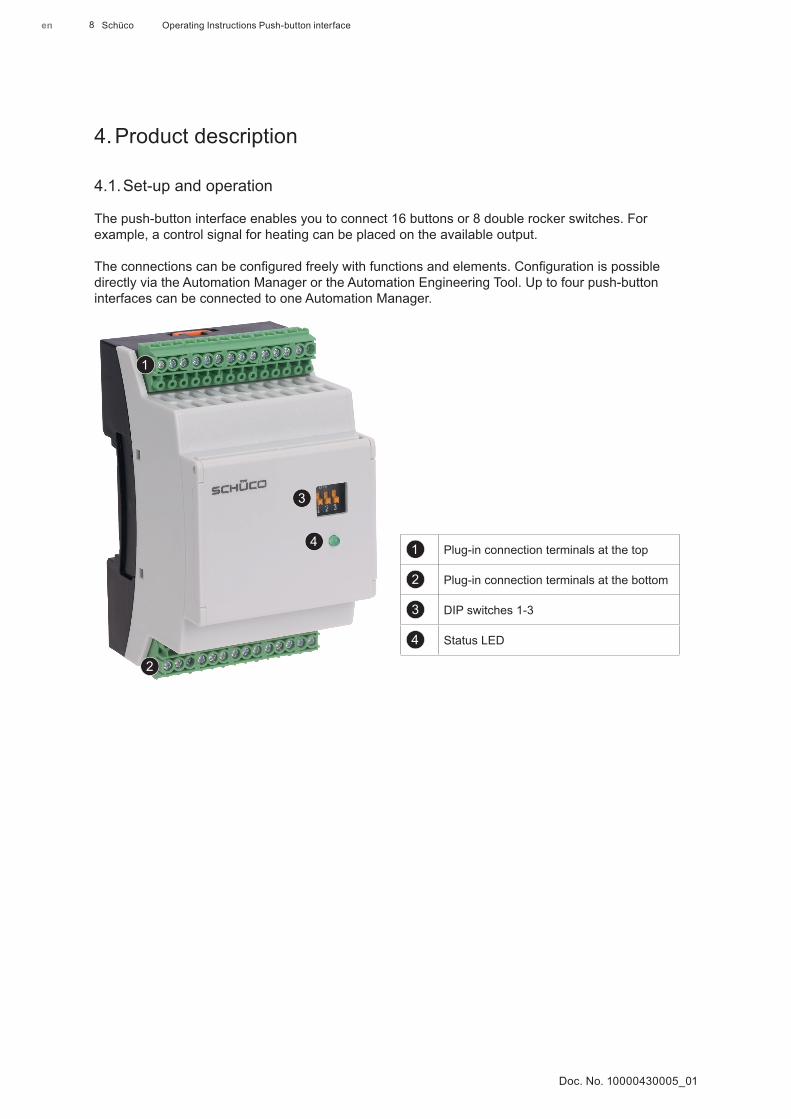
4.1. Set-up and operation
The push-button interface enables you to connect 16 buttons or 8 double rocker switches. For example, a control signal for heating can be placed on the available output.
The connections can be configured freely with functions and elements. Configuration is possible directly via the Automation Manager or the Automation Engineering Tool. Up to four push-button interfaces can be connected to one Automation Manager.
Plug-in connection terminals at the top
Plug-in connection terminals at the bottom
DIP switches 1-3
Status LED
Schüco enOperating Instructions Push-button interface 9
Doc. No. 10000430005_01
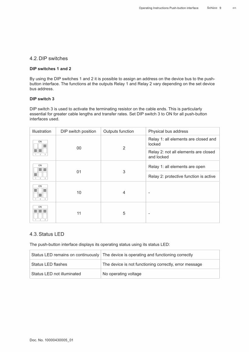
4.2. DIP switches
DIP switches 1 and 2
By using the DIP switches 1 and 2 it is possible to assign an address on the device bus to the push-button interface. The functions at the outputs Relay 1 and Relay 2 vary depending on the set device bus address.
DIP switch 3
DIP switch 3 is used to activate the terminating resistor on the cable ends. This is particularly essential for greater cable lengths and transfer rates. Set DIP switch 3 to ON for all push-button interfaces used.
Illustration DIP switch position Outputs function Physical bus address
1 2 3
ON
00 2
Relay 1: all elements are closed and locked
Relay 2: not all elements are closed and locked
1 2 3
ON
01 3Relay 1: all elements are open
Relay 2: protective function is active
1 2 3
ON
10 4 -
1 2 3
ON
11 5 -
4.3. Status LED
The push-button interface displays its operating status using its status LED:
Status LED remains on continuously The device is operating and functioning correctly
Status LED flashes The device is not functioning correctly, error message
Status LED not illuminated No operating voltage
Schücoen Operating Instructions Push-button interface 10
Doc. No. 10000430005_01
4.4. Technical data
Technical data
Housing Series installation housing, 3 module, for top hat rail, DIN EN 60175
Weight 113 g
Dimensions [mm]lll 53.4 x 89 x 60 mm
Protection rating IP 20 (installed in the distributor)
Status LED To monitor and for error feedback
Ambient temperature Operation: -10°C to +60°C
Transport/storage temperature Transport/storage: -40°C to +85°C
Relative humidity 5% to 93% (non-condensing)
Power supply DC 24 V
Current consumptionStatus LED 0.1 A
Safety class DIN EN 61140 lll
Installation Top hat rail installation on standardised profile track
5. Assembly and installation
WARNING!
Death or severe injury. ► All work on the product must only be carried out by qualified personnel. ► Before any work on the product, all power packs must be disconnected and protected against
anyone inadvertently switching them back on. ► Following each installation or alteration to the electrical system, carry out a test run to test all
functions. ► Only install in a suitable distributor or control cabinet.
5.1. Prerequisites for installation/assembly
1. Only install the push-button interface vertically so that the terminals are at the top and bottom.
2. After installing the unit, cover the entire terminal area.
3. Each group control unit with a maximum of four connected push-button interfaces requires a separate 24 V DC power pack for the auxiliary power supply (e.g. article no. 263 097).
Schüco enOperating Instructions Push-button interface 11
Doc. No. 10000430005_01
4. Lay the bus cables for the group control unit and the control cable for the momentary and maintained contact switches separately. When laying the cable ducts, the bus cables must be kept separate from the other cables.
5. Lay the bus cables and control cables at a distance from other cables supplying power.
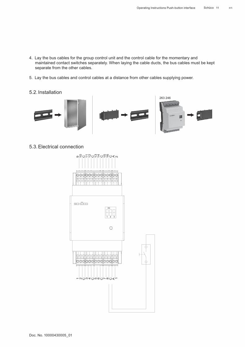
5.2. Installation263 246
5.3. Electrical connection
1 2 C 3 4 6
ON
1 2 3
5 7 8 A 1C C C
9 10 C 11 12 1413 15 16 A 2C C C
Schücoen Operating Instructions Push-button interface 12
Doc. No. 10000430005_01
6. Decommissioning and disposalThe materials used can be recycled. Observe the environmental requirements with regard to recycling, re-use and disposal of operating materials and components in accordance with the local, country-specific and international current technical regulations and official regulations. Make a contribution towards protecting our environment and dispose of the device at a collection point.
7. Service and support
At Schüco, a high level of customer satisfaction is our priority. If you require further information or encounter problems not dealt with in detail in this document, you can request the requisite information from Mechatronic Technical Support.
You can reach your contact partners on the service phone numbers below:
Hotline - Metal systems
Please contact your local branch.
Hotline - Mechatronics Tel.: +49 (0) 521 - 783 665
Fax: +49 (0) 521 - 783 836
E-mail: [email protected]
Schüco enOperating Instructions Push-button interface 13
Doc. No. 10000430005_01
Original operating instructions or (and)translation of original operating instructions
Doc
. No.
100
0043
0005
_01
Prin
ted
in G
erm
any
We
rese
rve
the
right
to m
ake
tech
nica
l cha
nges
and
to c
orre
ct e
rror
s. A
ll ill
ustra
tions
are
sim
ilar.
en
Schüco International KGKarolinenstraße 1-15 33609 Bielefeld Tel. +49 521 783-0 Fax +49 521 783-451 www.schueco.de