Embed Size (px)
Citation preview
ALUMEC 89

ALUMEC 89
2
SS-EN ISO 9001SS-EN ISO 14001
This information is based on our present state of knowledge and is intended to provide generalnotes on our products and their uses. It should not therefore be construed as a warranty ofspecific properties of the products described or a warranty for fitness for a particular purpose.
Classified according to EU Directive 1999/45/ECFor further information see our “Material Safety Data Sheets”.
Edition 6, 06.2011The latest revised edition of this brochure is the English version,which is always published on our web site www.uddeholm.com
ALUMEC 89
3
GeneralAlumec 89 is a high strength aluminium alloysupplied in the form of hot rolled, heat treatedplate. It undergoes a special cold stretchingoperation for maximum stress relieving.
Thanks to its high strength and good stabil-ity, Alumec 89 has become widely used in thetooling industry.
Delivery condition: heat treated to 146–180Brinell.
Alumec 89 has the following characteristicswhich make it suitable for many types of toolsespecially plastics moulds:
• Excellent machinabilityHigh cutting speeds, reduced machining time,lower tooling costs, quicker deliveries.
• Low weightThe low weight, which is approximately 1/3of the weight of steel, allows easier andmore convenient tool handling. Low inertiamakes it possible to speed up closing andopening of moulds.
• High thermal conductivityCycle times are reduced and less compli-cated cooling systems may be used.
• Good stabilityA special stress relieving operation guaran-tees minimal deformation during and aftermachining.
• Good corrosion resistanceGood resistance against all commonly usedplastics materials.
Application areasThe properties and characteristics whichAlumec 89 offers make it an ideal material forprototype tools and for moulding short andmedium length production runs which are notsubjected to high pressures or abrasiveplastics.
Considerably shorter tool making times,lower tooling costs and shorter cycle timesgive valuable savings both for the tool makerand the tool user when using Alumec 89.
Proto- Short Medium LongApplication areas types runs runs runs
Blow moulding X X X X
Vacuum forming X X X X
Foam moulding X X X (X)
RIM-moulding X X X (X)
Injection mouldingof thermoplastics X X (X)
Rubber moulding X X
Holders and supportplates, jigs and fixtures
Tooling category
• Suitable for surface treatmentsAlumec 89 can be hard anodized, hardchromium or nickel plated for increasedhardness, wear resistance and corrosionresistance.
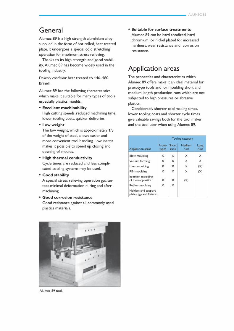
Alumec 89 tool.
ALUMEC 89
4
Cricket Software
PropertiesPhysical dataValues at room temperature unless statedotherwise.
Density kg/m3 2 830lbs/in3 0.102
Modulus of elasticity N/mm2 71 500psi 10.3 x 10⁶
Coefficient of thermal expansionper °C from 20°C to 100°C 23 x 10–6
per °F (68–212°F) 12.8 x 10⁻⁶
Thermal conductivity W/m °C 165Btu in/ft2h °F 1 144
Specific heat capacity J/kg °C 890Btu/lb °F 0.20
Tensile strength Yield strengthN/mm2 N/mm2
Plate (thickness), mm
> 10– 50 590 550> 50–100 570 520>100–150 550 500>150–200 535 485>200–300 430 365
Round bar Ø, mm
40 680 630100 680 620200 670 610
Note that the plate is tested in the transversedirection and the round bar in the lengthdirection.
Tensile strengthTensile strength values, which for most practi-cal purposes can be compared to compressionstrength values, should be regarded as typical.
Values at room temperature for differentplate thicknesses.
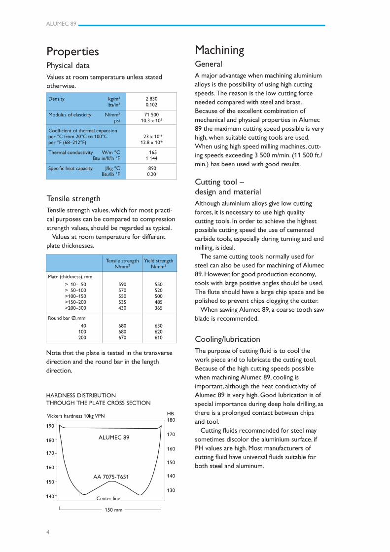
HARDNESS DISTRIBUTIONTHROUGH THE PLATE CROSS SECTION
MachiningGeneralA major advantage when machining aluminiumalloys is the possibility of using high cuttingspeeds. The reason is the low cutting forceneeded compared with steel and brass.Because of the excellent combination ofmechanical and physical properties in Alumec89 the maximum cutting speed possible is veryhigh, when suitable cutting tools are used.When using high speed milling machines, cutt-ing speeds exceeding 3 500 m/min. (11 500 ft./min.) has been used with good results.
Cutting tool –design and materialAlthough aluminium alloys give low cuttingforces, it is necessary to use high qualitycutting tools. In order to achieve the highestpossible cutting speed the use of cementedcarbide tools, especially during turning and endmilling, is ideal.
The same cutting tools normally used forsteel can also be used for machining of Alumec89. However, for good production economy,tools with large positive angles should be used.The flute should have a large chip space and bepolished to prevent chips clogging the cutter.
When sawing Alumec 89, a coarse tooth sawblade is recommended.
Cooling/lubricationThe purpose of cutting fluid is to cool thework piece and to lubricate the cutting tool.Because of the high cutting speeds possiblewhen machining Alumec 89, cooling isimportant, although the heat conductivity ofAlumec 89 is very high. Good lubrication is ofspecial importance during deep hole drilling, asthere is a prolonged contact between chipsand tool.
Cutting fluids recommended for steel maysometimes discolor the aluminium surface, ifPH values are high. Most manufacturers ofcutting fluid have universal fluids suitable forboth steel and aluminum.
190
180
170
160
150
140
Vickers hardness 10kg VPN
150 mm
ALUMEC 89
AA 7075-T651
HB180
170
160
150
140
130
Center line
ALUMEC 89
5
Cutting datarecommendationsThe cutting data below are to be consideredas guiding values which must be adapted toexisting local conditions. Further information isgiven in the technical report “Cutting datarecommendations”.
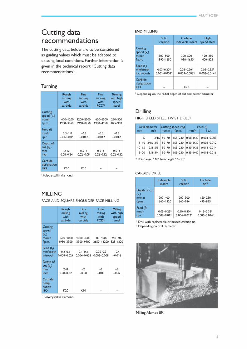
Milling Alumec 89.
Rough Fine Fine Turningturning turning turning with highwith with with speed
carbide carbide PCD1) steel
Cuttingspeed (vc)m/min 600–1200 1200–2500 600–1500 250–300f.p.m. 1980–3960 3960–8250 1980–4950 825–990
Feed (f)mm/r 0.3–1.0 –0.3 –0.3 –0.3i.p.r. 0.012–0.04 –0.012 –0.012 –0.012
Depth ofcut (ap)mm 2–6 0.5–2 0.5–3 0.5–3inch 0.08–0.24 0.02–0.08 0.02–0.12 0.02–0.12
CarbidedesignationISO K20 K10 – –
1) Polycrystallin diamond.
Turning
Rough Fine Fine Millingmilling milling milling with highwith with with speed
carbide carbide PCD1) steel
Cuttingspeed(vc)m/min 600–1000 1000–3000 800–4000 250–400f.p.m. 1980–3300 3300–9900 2650–13200 825–1320
Feed (fz)mm/tooth 0.2–0.6 0.1–0.2 0.05–0.2 –0.4in/tooth 0.008–0.024 0.004–0.008 0.002–0.008 –0.016
Depth ofcut (a
p)
mm 2–8 –2 –2 –8inch 0.08–0.32 –0.08 –0.08 –0.32
Carbidedesig-nationISO K20 K10 – –
MILLINGFACE AND SQUARE SHOULDER FACE MILLING
1) Polycrystallin diamond.
END MILLING
Solid Carbide Highcarbide indexable insert speed steel
Cuttingspeed (v
c)
m/min 300–500 300–500 120–250f.p.m. 990–1650 990–1650 400–825
Feed (fz)
mm/tooth 0.03–0.201) 0.08–0.201) 0.05–0.351)
inch/tooth 0.001–0.0081) 0.003–0.0081) 0.002–0.0141)
CarbidedesignationISO – K20 –
1) Depending on the radial depth of cut and cutter diameter
DrillingHIGH SPEED STEEL TWIST DRILL1)
Drill diameter Cutting speed (vc) Feed (f) mm inch m/min f.p.m. mm/r i.p.r.
– 5 –3/16 50–70 165–230 0.08–0.20 0.003–0.008
5–10 3/16–3/8 50–70 165–230 0.20–0.30 0.008–0.012
10–15 3/8–5/8 50–70 165–230 0.30–0.35 0.012–0.014
15–20 5/8–3/4 50–70 165–230 0.35–0.40 0.014–0.016
1) Point angel 118° helix angle 16–30°
Indexable Solid Carbideinsert carbide tip1)
Depth of cut(v
c)
m/min 200–400 200–300 150–250f.p.m. 660–1320 660–984 495–825
Feed (f)mm/r 0.05–0.252) 0.10–0.302) 0.15–0.352)
i.p.r. 0.002–0.012) 0.004–0.0122) 0.006–0.0142)
CARBIDE DRILL
1) Drill with replaceable or brazed carbide tip2) Depending on drill diameter
ALUMEC 89
6
Polishing guidelinesGeneralMaintain a clean work environment and ensurethat the work piece is flushed with an appro-priate industrial solvent to prevent accumula-tion of polishing debris.
Use large tools wherever possible to preventhigh levels of localized pressure leading tosurface degradation.
Renew grinding paper frequently and changedirection of grinding between grades. Whenworking towards a mirror finish use copiousquantities of lubricant such as a light oil.
See separate leaflet “Polishing of Tool Steel”for detailed information on polishing.
TechniquesBoth mechanical and manual techniques maybe used. When seeking a mirror finish the useof power tools should be avoided.
MediaCarborundum paper should be used forgrinding starting with grades 300 through to800. When seeking a mirror finish, continuewith 1200 grade paper and if necessaryfollowed with 6 micron/3 micron diamondpaste.
Electrical DischargeMachining (EDM)Machine settings are similar to those used forsteel but may need more power to stabilize.Metal re-moval rates are 3 to 4 times that ofsteel necessitating good flushing to avoidarcing.
Copper electrodes give best results andshow less wear. Roughing electrodes are rarelyrequired.
GrindingA general grinding wheel recommendation isgiven below. For grinding of Alumec 89 usesilicon carbide abrasive. Cutting oil is recom-mended as grinding fluid.
Type of grinding Wheel recommendation
Face grinding straight wheel C 46 H V
Face grinding segments C 24 G V
Cylindrical grinding C 60 J V
Internal grinding C 46 H V
Profile grinding C 100 L V
ALUMEC 89
7
Repair weldingAlumec 89 may be repair welded using eitherMetal Inert Gas (MIG) or Tungsten Inert Gas(TIG) pro-cesses, though TIG is not recom-mended for large scale repairs.
General guidelines
EQUIPMENT
400 Amps rating, Wire Feed Motor 7.5–10 m/min (25–33 f.p.m.) (compared to3.7 m/min [12 f.p.m.] for steel).
WELDING WIRE
AA5356 (Al 5 % Mg), AA5556A (Al 5.2 % Mg)or AA5087 (Al 4.5 % MgMnZr).MIG 1.6 mm (0.063 in.) diameter. TIG 2.4–3.2 mm (0,095–0,126 in.).
PRE-WELD PREPARATION
Vertical faces should be machined to an angleand surfaces to be welded, degreased. Oxidelayer must then be removed using rotary wirebrushing and welding carried out within eighthours.
Surface treatmentHard anodising
Alumec 89 can be hard anodised for higherwear resistance, giving a surface hardnessequivalent to about 65 HRC in steel. Usualcoating thickness is 20–50 µm. Anodising isused to a limited degree in mould cavities dueto the difference in expansion of the surfacelayer relative to the underlying aluminium. Thiscan lead to hairline cracking, spoiling thesurface appearance of mouldings. This surfaceis usually acceptable on non-moulding toolparts, such as slides, wear guides, leader pinsand bushes, ejector pins, etc.
Note: The anodising will cause dimensionalchanges in the workpiece, and allowanceshould, therefore, be made. Increase indimension is about 50% of the oxide layerthickness. The oxide layer may be impregnatedwith PTFE to reduce adhesion of the plastic.
Hard Chrome PlatingHardness levels up to and equivalent to80 HRC are possible using processes whichhave been developed for aluminium alloys.Plated layer thickness is typically 0.1–0.2 mm(0.004" to 0.008").
Photo-etchingAlumec 89 is perfecat for photo-etchingthanks to its homogeneous structure.
Chemical Nickel PlatingHardness levels equivalent to 50 HRC arepossible. Plated layer thickness is typically0.03–0.1 mm (0.001"–0.004") whilst adhesionand corrosion resistance are generally superiorto a chrome plated finish.
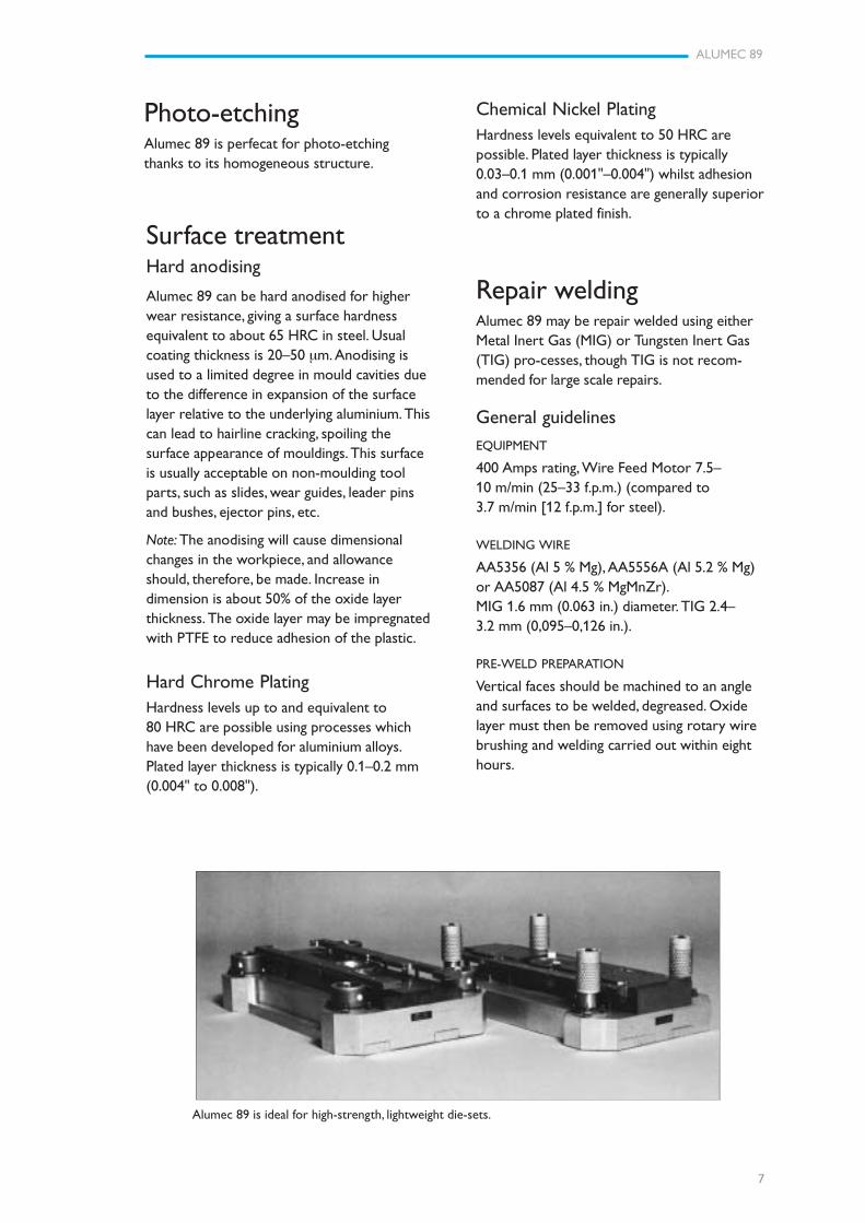
Alumec 89 is ideal for high-strength, lightweight die-sets.

ALUMEC 89
8
Further informationContact your nearest Uddeholm representa-tive for more information about aluminiumand special steel for tools.
PRE-HEATING
Pre-heat to 50–130°C (120–270°F) to offsetthe chilling effect and high thermal conduc-tivity of Alumec 89. Maximum metal tem-perature during welding should not exceed200°C (390°F) in order to avoid cracking afterwelding.

ALUMEC 89
9

ALUMEC 89
10
www.assab.com www.uddeholm.com
Network of excellenceUDDEHOLM is present on every continent. This ensures you
high-quality Swedish tool steel and local support wherever you
are. ASSAB is our wholly-owned subsidiary and exclusive sales
channel, representing Uddeholm in various parts of the world.
Together we secure our position as the world’s leading supplier
of tooling materials.
UD
DEH
OLM
110604.200 / TR
YC
KERI KN
APPEN
, KAR
LSTA
D 201106
UDDEHOLM is the world’s leading supplier of tooling materials. This
is a position we have reached by improving our customers’ everyday
business. Long tradition combined with research and product develop-
ment equips Uddeholm to solve any tooling problem that may arise.
It is a challenging process, but the goal is clear – to be your number one
partner and tool steel provider.
Our presence on every continent guarantees you the same high quality
wherever you are. ASSAB is our wholly-owned subsidiary and exclusive
sales channel, representing Uddeholm in various parts of the world.
Together we secure our position as the world’s leading supplier of
tooling materials. We act worldwide, so there is always an Uddeholm
or ASSAB representative close at hand to give local advice and support.
For us it is all a matter of trust – in long-term partnerships as well as in
developing new products. Trust is something you earn, every day.
For more information, please visit www.uddeholm.com, www.assab.com
or your local website.