Embed Size (px)
DESCRIPTION
Paper presented at the Region II 2010 AIAA Student Conference
Citation preview
1 American Institute of Aeronautics and Astronautics
Altitude Compensating Effects of Aerospike Nozzles
Tyler R. Maddox1
University of Central Florida, Orlando, FL, 32816 and Eric J. McClellan2
The de Laval nozzle has proven to be effective over the past 50 years but in order for the human race to explore further into space, a more efficient nozzle will be required. The aerospike nozzle is a type of altitude compensating nozzle that maintains its efficiency over a wide range of ambient conditions, making it ideal for future missions. Types of aerospike nozzles include the linear, toroidal, and truncated. The limiting factors including truncation ratios and cooling limitations of each type of nozzle can be optimized with CFD analysis and differential throttling of the injectors. Different shock formations can propagate through the exhaust flow greatly reducing or increasing the thrust. This paper will explore the performance characteristics of each nozzle, and compare it to the de Laval nozzle.
Nomenclature
Ae = Projected area of the aerospike nozzle At = Total thruster throat area Pb = Base pressure Pe = Thruster Exit Pressure Pol = Chamber pressure M = Mach number γ = Specific heat ratios of propellants
I. Introduction In 1897 a Swedish inventor by the name of Gustaf de Laval created the de Laval nozzle also known as the bell
shaped nozzle. The bell nozzle is a converging-diverging nozzle, which allows the gas flow to accelerate through the nozzle at a supersonic speed. The change in the cross-sectional area in the nozzle creates a sonic speed when it converges at the throat. If the flow velocity is not sonic at the throat, then it has an extreme value which is a maximum if the velocity at the initial section of the nozzle is subsonic, or a minimum if it is supersonic2. Therefore, if the diverging section is to obtain supersonic flow, the velocity at the throat must always be at sonic speed. Since this condition must always be met, the velocity of the flow in the diverging section can never be regulated, and will expand past optimal conditions when higher altitudes are reached. Ideally the pressure at the exit of the nozzle would be equivalent to the ambient pressure creating max thrust2. When the altitude changes, the ambient pressure also changes causing an alteration in the exhaust plume and therefore the thrust. This change in ambient pressure can cause the exhaust plume to be either overexpanded or underexpanded, which causes a loss in thrust and efficiency in the bell nozzle. An attempt to overcome the changing exhaust plume is the aerospike nozzle. Developed in the early 1960’s by Rocketdyne, the aerospike nozzle uses two sloped nozzle surfaces in place of the bell nozzle. The surfaces are constructed into an inverse parabolic shape converging at the end to a point. Along the upper edge of the nozzle there are a series of combustion chambers that direct the hot gas almost parallel to the surface of the nozzle to create thrust. Unlike the bell nozzle, the exhaust plume from an aerospike nozzle is open on one side and thus free to expand. The open side allows the exhaust plume to compensate for the change in pressure. This helps the engine maintain optimum efficiency regardless of the change in altitude and ambient pressure. The three different variations of the aerospike nozzle are: linear, toroidal, and truncated.
II. Theory In the past, rockets have utilized the De Laval or bell nozzle to launch rockets into space, but advanced rocketry
systems will require performance over a wider range of ambient conditions7. These rockets will have to outperform
1 Student, Department of Mechanical Materials and Aerospace Engineering, AIAA Student Member 2 Student, Department of Mechanical Materials and Aerospace Engineering, AIAA Student Member
2 American Institute of Aeronautics and Astronautics
conventional systems in achieving a reliable and cost effective launch to space. By changing the concept of the nozzle of the system, performance gains can be achieved.
Nozzles that adapt to the surrounding conditions are classified as altitude compensating nozzles (ACN). Altitude compensating implies that the nozzle being used can adapt to perform over any given range of altitudes including the vacuum of space. This is precisely what the aerospike nozzle and its variations, the linear, toroidal, and truncated designs can achieve. Instead of expanding the flow inside of a nozzle, the flow is expanded outside the nozzle along the sides.
In the aerospike nozzle and its variations, two conditions affect the overall performance: static sidewall pressure forces acting on the nozzle walls and the pressure forces acting on the base of the nozzle7. Depending on the type of aerospike nozzle and the ambient conditions, the pressure differences can vary widely. In linear and truncated aerospikes, the base pressure is an important component of the thrust. Because only a portion of the nozzle is used, the pressure on the base of the nozzle directly affects the component of the thrust parallel to the exhaust flow. In a toroidal, or full aerospike, the static pressure on the walls of the nozzle is the only driving factor because there is no base in this type of nozzle.
ACN are slightly less efficient than bell nozzles for a given altitude, but are more efficient at every other altitude. Whereas aerospike nozzles will adapt the plume shape with increasing altitudes, bell nozzles are optimized for a single altitude. In bell nozzles, before optimal altitude is reached, the exhaust plume is underexpanded; after the optimal altitude is reached, the plume becomes overexpanded. The performance advantages are difficult to validate by ground test because of the static ambient conditions11. Tests must be conducted in a closed chamber so the pressure can be regulated to follow the pressure at higher altitudes.
Looking at an adiabatic flow of the injected gas around the aerospike nozzle, the parameters affecting the expansion rate of the flow and thus the thrust of the nozzle, are the curvature of the nozzle, the type of ACN, and whether internal cooling is used. The biggest setback facing the group of ACN today are the limitations on thermal cooling and the materials selection. Temperatures on the surface of a nozzle without proper cooling will cause the surface to ablate, depleting the performance gain with constant usage.
A. Linear Aerospike Nozzle
Linear aerospike nozzles get their name from expanding the gas flow from a combustion chamber in one dimension. The linear aerospike nozzle has the benefit of being stackable because of the one dimensional flow around the walls of the nozzle. Single engines can be positioned side by side unlike circular aerospike nozzles. If multiple linear aerospike nozzles are stacked alongside one another, they create the same effect as an airfoil placed inside a wind tunnel of equal lengths. The flow along the surface can be assumed laminar, and the only region of concern is the endpoints of the linear nozzle stacks. This one dimensional flow also lends itself to easier calculations when determining the thrust performance from the nozzle.
With the ability to be stacked, linear aerospike propulsion systems can gain significant performance with little weight addition. The single stage to orbit (SSTO) proposition of the X-33 project incorporated a stacked linear aerospike propulsion system called the XRS-22009. This engine contained multiple stacks of linear aerospike nozzles which were incorporated into the structure of the vehicle9. Having this integration of the engine reduced weight by acting as both the engine and the aft structure. The integration of the linear aerospike engine produced a beneficial side effect of reducing the base drag on the vehicle by maintaining the laminar flow across the structure to reduce the wake of the flow12. By increasing thrust and reducing drag on the spacecraft, the XRS-2200 could send heavier payloads into orbit using a SSTO approach. B. Toroidal Aerospike Nozzle
The toroidal aerospike or full aerospike is a circular nozzle where the flow is expanded in three dimensions. This design was the original ideal concept when considering propulsion in a vacuum. Because there is no base in the toroidal aerospike nozzle, only sidewall pressures need to be determined, simplifying calculations for thrust.
This nozzle works well for small spacecraft where significant thrust is not needed as in launch vehicles. In 2004, NASA began experimenting with a toroidal aerospike in the Dryden Aerospike Rocket Test (DART). The test rocket reached an altitude of 30,000 feet, and served to validate actual flight conditions with ninety six percent efficiency in converting the flow expansion into thrust10. In the nozzle, the gas travels along the walls of the inverse parabolic shape and expands in relation to the ambient conditions. Since ambient pressure is keeping the flow against the nozzle walls, the gas flow will expand to equalize the difference in pressures. This adjustment will maintain optimal plume expansion through the duration of flight.
3 American Institute of Aeronautics and Astronautics
C. Truncated Nozzle A more common use of the aerospike principal is to truncate the nozzle halfway, saving the weight of the “spike”
while only losing some of the performance gained from fully expanding the flow. By truncating the nozzle, both base and sidewall pressures will have effects on performance. At low altitudes, the flow does not separate from the walls because supersonic shock waves propagate through the flow8. When the flow reaches the edge of the nozzle at the base region, however, losses will occur because the gas will not fully expand over the short region. The loss of performance caused by truncation can be largely offset by injecting a small percentage of the gas flow into the recirculating region on the base of the nozzle called base bleed8. This injection of gas into the recirculating region creates a higher pressure on the base plate of the nozzle and allows the transverse flow over the walls of the nozzle to pass over the recirculating region as if the nozzle was not truncated9. The high pressure recirculating region retains the shape of a virtual spike, receiving full benefits of a toroidal aerospike nozzle while sacrificing a small amount of flow to the base bleed.
Since the boundary layer continues in the reverse parabolic arc, it bends around the wall discontinuity7. Near the converging point of the recirculating region, the high velocity flow around the nozzle distorts the plume shape while compressing the virtual spike. The plume formed immediately after the recirculating region therefore becomes overexpanded. To counter the overexpansion, the flow turns on itself which generate internal and recompression shocks7.
III. Numerical Analysis As previously stated, base pressure is a large factor in the overall performance of the aerospike nozzle.
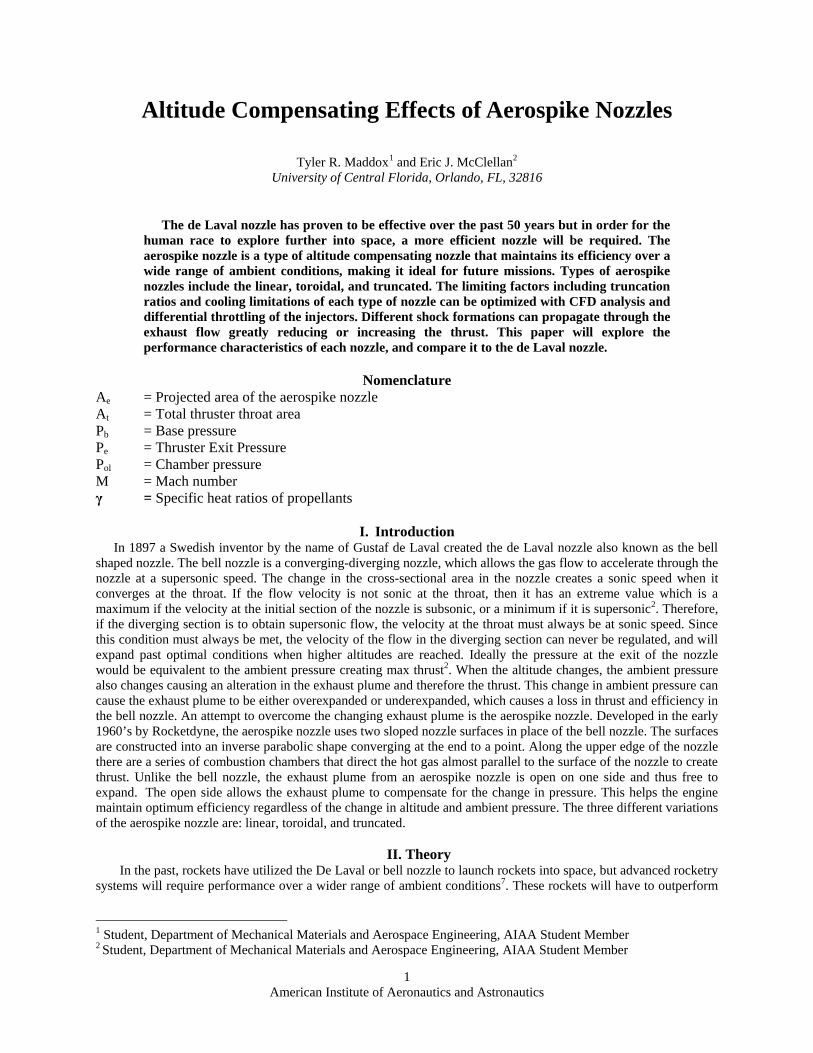
Depending on the ambient pressure, and the pressure of the flow around the nozzle, two wake formations can develop in the base region of a truncated aerospike nozzle: open or closed as seen in Fig. 1. An open wake occurs at low pressure ratios where the base pressure is open to ambient conditions7.A closed wake occurs at high pressure ratios where the flow converges onto itself, encapsulating the base in a region of recirculating gas7. Since the gas is unable flow past the boundary of the outer flow as in an open wake, the pressure remains constant for a closed wake flow.
For the open wake, the base pressure decreases with increasing altitude because of the lower pressure. Having a diminishing value for the base pressure greatly decreases the thrust from the nozzle. Having the base bleed recirculate in a closed wake scenario, the truncated nozzle acts like a toroidal aerospike nozzle because of the virtual spike created by the base bleed.
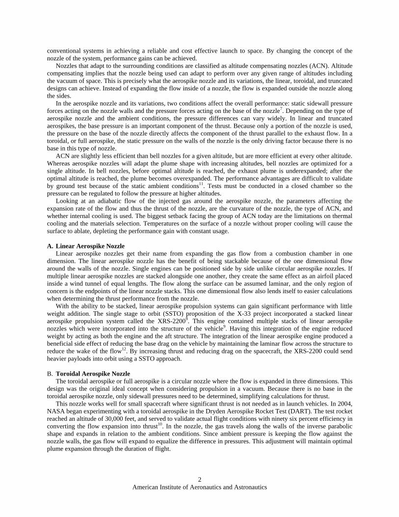
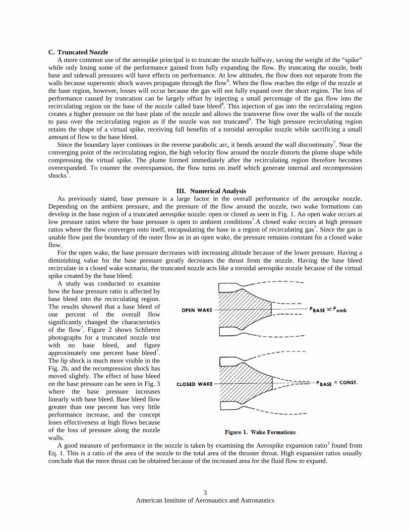
A study was conducted to examine how the base pressure ratio is affected by base bleed into the recirculating region. The results showed that a base bleed of one percent of the overall flow significantly changed the characteristics of the flow7. Figure 2 shows Schlieren photographs for a truncated nozzle test with no base bleed, and figure approximately one percent base bleed7. The lip shock is much more visible in the Fig. 2b, and the recompression shock has moved slightly. The effect of base bleed on the base pressure can be seen in Fig. 3 where the base pressure increases linearly with base bleed. Base bleed flow greater than one percent has very little performance increase, and the concept loses effectiveness at high flows because of the loss of pressure along the nozzle walls.
A good measure of performance in the nozzle is taken by examining the Aerospike expansion ratio3 found from Eq. 1. This is a ratio of the area of the nozzle to the total area of the thruster throat. High expansion ratios usually conclude that the more thrust can be obtained because of the increased area for the fluid flow to expand.
4 American Institute of Aeronautics and Astronautics
𝐴𝐴𝑒𝑒𝐴𝐴𝑡𝑡
=� 2𝛾𝛾 + 1�
𝛾𝛾+12(𝛾𝛾−1) �𝑃𝑃𝑜𝑜𝑜𝑜𝑃𝑃𝑒𝑒
�𝛾𝛾+12𝛾𝛾
� 2𝛾𝛾 − 1 ��
𝑃𝑃𝑜𝑜𝑜𝑜𝑃𝑃𝑒𝑒�𝛾𝛾−1𝛾𝛾− 1�
(1)
The pressure distribution on the nozzle
contour is computed by using the Navier-Stokes Equations5. An accurate CFD model predicting the base pressure and thermal environment however, is difficult to develop because of the turbulence in the region1. Marshall Space Flight Center attempted to address the problems when the proposed X-33 program was in development by using a Finite-Difference Navier-Stokes (FDNS) model for the fluid flow1. The analysis has been validated for convective heat transfer inside rocket thrust chambers1.
The highest level of heat fluctuation on the nozzle is along the walls near the base of an aerospike1. Normally, these heating issues are only prevalent at low altitudes where ambient pressure is at its highest, but a phenomenon called Plume-induced flow separation (PIFS) is thought to occur at high altitudes1. With PIFS, exhaust gas from the recirculating region can be drawn onto the walls which will cause a fluctuation in heat transfer leading to the burning of the nozzle material1. Despite occurring on the propulsion system of a Saturn V rocket, PIFS has yet to be observed for ACN simulated at various altitudes. This lack of PIFS is thought to be caused by the limiting of the plume expansion angle because of shock wave propagation in the gas flow and from low pressures in the recirculating region.
5 American Institute of Aeronautics and Astronautics
IV. Throttling and Vector Control Because of the uniaxial thrust of the bell nozzle, vector control has to be accomplished by altering the orientation
of the engine through the use of a gimbaling structure11. The structural components of the gimbaling device add significant weights to the propulsion system. To control an aerospike engine, thrust vector control (TVC) is accomplished by throttling the injectors since they can be individually controlled9. Being able to regulate the injectors eliminates the need to incorporate bulky support structures because the nozzle is always stationary relative to the spacecraft6. The power required to actuate the differential throttling valves is considerably less than the power required to gimbal a large nozzle and have a much faster response time11.
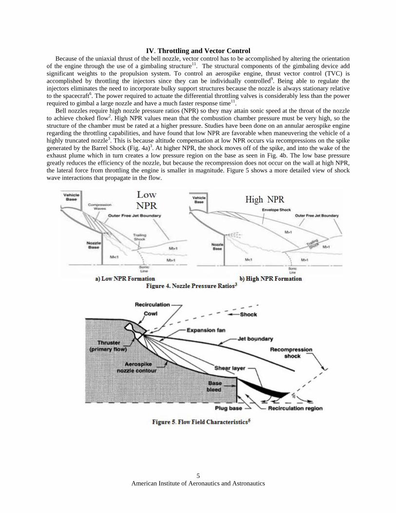
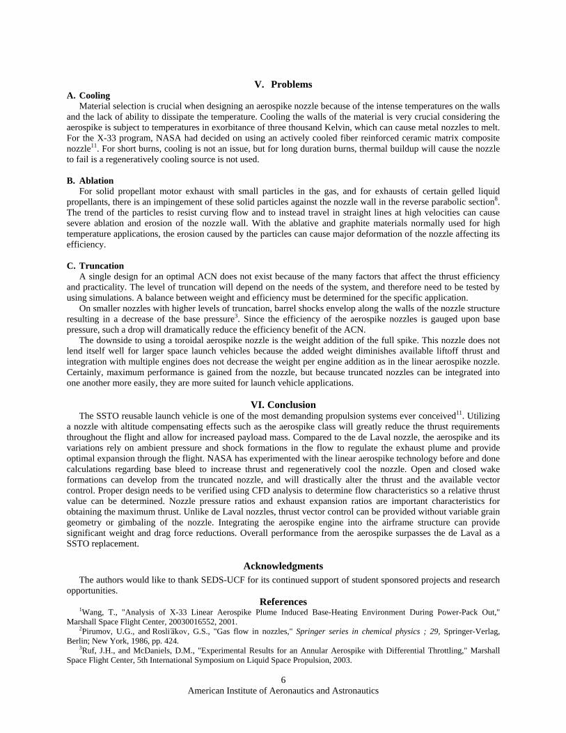
Bell nozzles require high nozzle pressure ratios (NPR) so they may attain sonic speed at the throat of the nozzle to achieve choked flow2. High NPR values mean that the combustion chamber pressure must be very high, so the structure of the chamber must be rated at a higher pressure. Studies have been done on an annular aerospike engine regarding the throttling capabilities, and have found that low NPR are favorable when maneuvering the vehicle of a highly truncated nozzle3. This is because altitude compensation at low NPR occurs via recompressions on the spike generated by the Barrel Shock (Fig. 4a)3. At higher NPR, the shock moves off of the spike, and into the wake of the exhaust plume which in turn creates a low pressure region on the base as seen in Fig. 4b. The low base pressure greatly reduces the efficiency of the nozzle, but because the recompression does not occur on the wall at high NPR, the lateral force from throttling the engine is smaller in magnitude. Figure 5 shows a more detailed view of shock wave interactions that propagate in the flow.
6 American Institute of Aeronautics and Astronautics
V. Problems
A. Cooling Material selection is crucial when designing an aerospike nozzle because of the intense temperatures on the walls
and the lack of ability to dissipate the temperature. Cooling the walls of the material is very crucial considering the aerospike is subject to temperatures in exorbitance of three thousand Kelvin, which can cause metal nozzles to melt. For the X-33 program, NASA had decided on using an actively cooled fiber reinforced ceramic matrix composite nozzle11. For short burns, cooling is not an issue, but for long duration burns, thermal buildup will cause the nozzle to fail is a regeneratively cooling source is not used. B. Ablation
For solid propellant motor exhaust with small particles in the gas, and for exhausts of certain gelled liquid propellants, there is an impingement of these solid particles against the nozzle wall in the reverse parabolic section8. The trend of the particles to resist curving flow and to instead travel in straight lines at high velocities can cause severe ablation and erosion of the nozzle wall. With the ablative and graphite materials normally used for high temperature applications, the erosion caused by the particles can cause major deformation of the nozzle affecting its efficiency. C. Truncation
A single design for an optimal ACN does not exist because of the many factors that affect the thrust efficiency and practicality. The level of truncation will depend on the needs of the system, and therefore need to be tested by using simulations. A balance between weight and efficiency must be determined for the specific application.
On smaller nozzles with higher levels of truncation, barrel shocks envelop along the walls of the nozzle structure resulting in a decrease of the base pressure3. Since the efficiency of the aerospike nozzles is gauged upon base pressure, such a drop will dramatically reduce the efficiency benefit of the ACN.
The downside to using a toroidal aerospike nozzle is the weight addition of the full spike. This nozzle does not lend itself well for larger space launch vehicles because the added weight diminishes available liftoff thrust and integration with multiple engines does not decrease the weight per engine addition as in the linear aerospike nozzle. Certainly, maximum performance is gained from the nozzle, but because truncated nozzles can be integrated into one another more easily, they are more suited for launch vehicle applications.
VI. Conclusion
The SSTO reusable launch vehicle is one of the most demanding propulsion systems ever conceived11. Utilizing a nozzle with altitude compensating effects such as the aerospike class will greatly reduce the thrust requirements throughout the flight and allow for increased payload mass. Compared to the de Laval nozzle, the aerospike and its variations rely on ambient pressure and shock formations in the flow to regulate the exhaust plume and provide optimal expansion through the flight. NASA has experimented with the linear aerospike technology before and done calculations regarding base bleed to increase thrust and regeneratively cool the nozzle. Open and closed wake formations can develop from the truncated nozzle, and will drastically alter the thrust and the available vector control. Proper design needs to be verified using CFD analysis to determine flow characteristics so a relative thrust value can be determined. Nozzle pressure ratios and exhaust expansion ratios are important characteristics for obtaining the maximum thrust. Unlike de Laval nozzles, thrust vector control can be provided without variable grain geometry or gimbaling of the nozzle. Integrating the aerospike engine into the airframe structure can provide significant weight and drag force reductions. Overall performance from the aerospike surpasses the de Laval as a SSTO replacement.
Acknowledgments The authors would like to thank SEDS-UCF for its continued support of student sponsored projects and research
opportunities. References
1Wang, T., "Analysis of X-33 Linear Aerospike Plume Induced Base-Heating Environment During Power-Pack Out," Marshall Space Flight Center, 20030016552, 2001.
2Pirumov, U.G., and Rosli ︠ a︡kov, G.S., "Gas flow in nozzles," Springer series in chemical physics ; 29, Springer-Verlag, Berlin; New York, 1986, pp. 424.
3Ruf, J.H., and McDaniels, D.M., "Experimental Results for an Annular Aerospike with Differential Throttling," Marshall Space Flight Center, 5th International Symposium on Liquid Space Propulsion, 2003.
7 American Institute of Aeronautics and Astronautics
4Diem, H.G., and Kirby, F.M., "Linear Aerospike Engine Study," Lewis Research Center, NASA Cr-135231, 1977. 5Korte, J.J., Salas, A.O., Dunn, H.J., "Multidisciplinary Approach to Linear Aerospike Nozzle Optimization," Langley
Research Center, NASA-TM-110326, 1997. 6Scott, J. , “Aerospike Engine,” November 1999. [http://www.aerospaceweb.org/design/aerospike/main.shtml. Accessed
01/03/2010] 7Gross, K.W., "Performance Analysis of Aerospike Rocket Engines," Marshall Space Flight Center, 19730004121, f72. 8Sutton, G., and Biblarz, O., "Real Nozzles," Rocket Propulsion Elements, John Wiley and Sons, New York, 2010, pp. 82-87. 9Jackson, J.E., Espenschied, E., and Klop, J., "The Control System for the X-33 Linear Aerospike Engine," Marshall Space
Flight Center, NAS 1.26:207923, 1998. 10Bui, T., "The Dryden Aerospike Rocket Test," Dryden Flight Research Center, 20060056096, 2006. 11Vinson, J., "X-33 Linear Aerospike Engine," Aerospace America, 1998, 12”Linear Aerospike Engine-Propulsion for the X-33 Vehicle, “FS-2000-09-174-MSFC, Marshall Space Flight Center,
Alabama, August 2000. [http://www.nasa.gov/centers/marshall/news/background/facts/aerospike.html. Accessed 01/03/2010.]


![Compensating Teams[1]](https://img.pdfslide.us/doc/110x75/577d27c61a28ab4e1ea4cb06/compensating-teams1.jpg)