Embed Size (px)
Citation preview
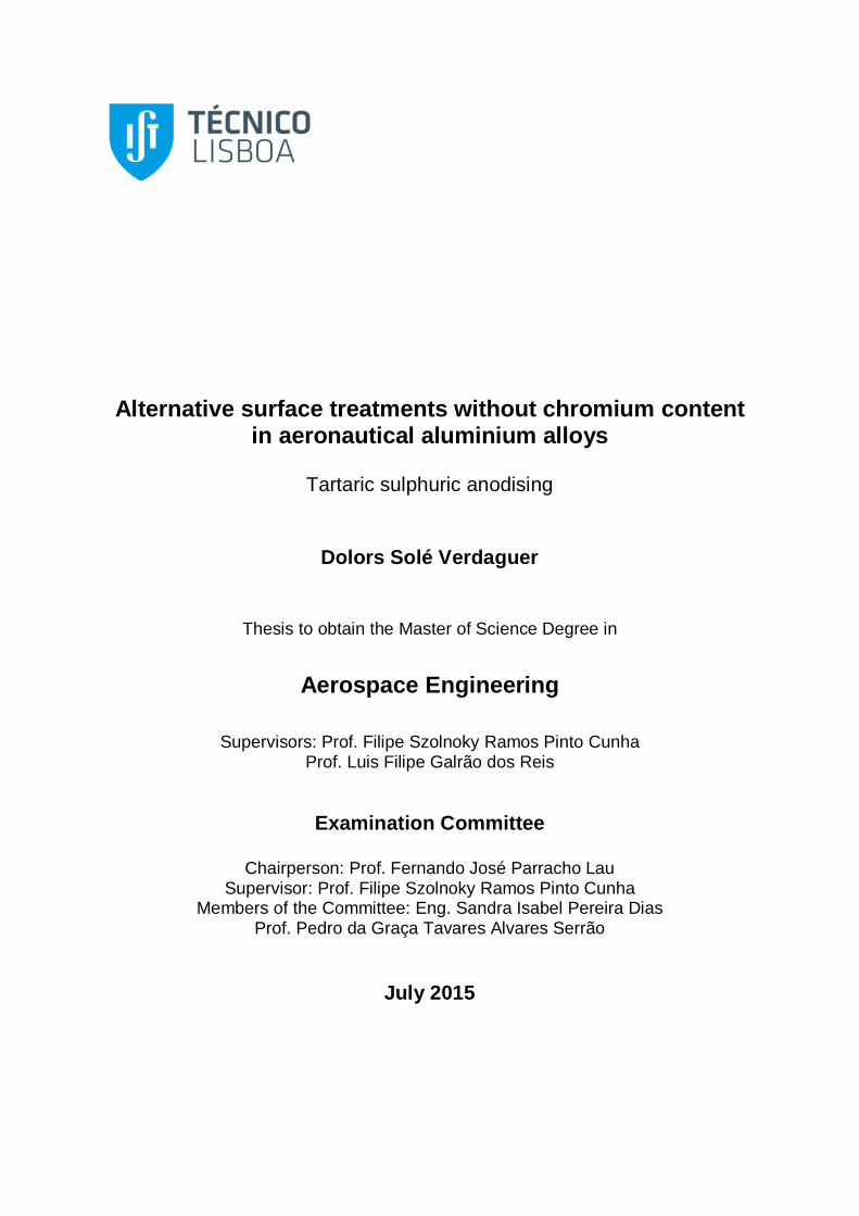
Alternative surface treatments without chromium content in aeronautical aluminium alloys
Tartaric sulphuric anodising
Dolors Solé Verdaguer
Thesis to obtain the Master of Science Degree in
Aerospace Engineering
Supervisors: Prof. Filipe Szolnoky Ramos Pinto Cunha Prof. Luis Filipe Galrão dos Reis
Examination Committee
Chairperson: Prof. Fernando José Parracho Lau Supervisor: Prof. Filipe Szolnoky Ramos Pinto Cunha
Members of the Committee: Eng. Sandra Isabel Pereira Dias Prof. Pedro da Graça Tavares Alvares Serrão
July 2015
ABSTRACT
Aluminium and its alloys are widely used in the aviation sector due to their lightweight and their high
specific strength. They require surface treatments in order to improve their corrosion resistance, such
as anodising which has traditionally carried out using a chromic acid bath.
Although chromium has been regularly used in industry for more than a century and its applications
are many and varied, progressively restrictions and rigorous controls have been imposed because of
environmental, toxicological and health concerns.
The objective of this thesis is to study the tartaric-sulphuric anodising, an alternative anodising
process without hexavalent chromium. The tests were performed on three aluminium alloys AA2024-
T3, AA7175-T7351 and AA6061-T6. It was analysed the thickness, the coating weight, the corrosion
resistance and the loss of the absorption power achieved by the anodic film with excellent results.
Also, it was studied the compatibility of the anodic coating with various current post-treatments. It was
tested three different sealings: with hot water, with potassium dichromate and with the chemical
conversion coating Bonderite® M-CR 1200S Aero. On samples without sealing, it was applied an
epoxy primer and a polyurethane topcoat in use by Airbus. It was demonstrated the compatibility of all
of them with the anodic film, except in the case of the Bonderite® M-CR 1200S Aero on the AA2024-
T3 that did not pass the corrosion test.
Finally, it was analysed the performance of a new non-chromate product for the acid etching process.
The alternative product studied, as a substitute of the current bath with sodium dichromate, was the
Bonderite® Smutgo NCB that achieved successful results.
Keywords Aluminium alloys, TSA (Tartaric-Sulphuric Anodising), CAA (Chromic Acid Anodising), Anodising
RESUMO
O alumínio e as suas ligas são amplamente utilizadas no sector da aviação devido ao seu baixo peso
específico e elevada resistência específica. Porém estes materiais necessitam de tratamentos de
superfície, a fim de melhorar a sua resistência à corrosão, tais como a anodização, a qual
tradicionalmente é realizada num banho de ácido crómico.
Apesar da utilização do cromio na indústria há mais de cem anos, com muitas e variadas aplicações,
têm surgido progressivamente restrições e controlos rigorosos por causa de preocupações
ambientais, toxicológicos e de saúde.
O objetivo desta tese é o estudo de um processo de anodização alternativo sem cromo hexavalente,
a chamada anodização tartárica-sulfúrica. Os testes foram realizados em três ligas de alumínio
AA2024-T3, AA7175-7351 e AA6061-T6. Foi analisada analizada a espessura, o peso anódico, a
resistência à corrosão e a perda do poder de absorção conseguida pela película anódica. Foram
obtidos resultados muito promissores.
Também foi estudada a compatibilidade da película anódica com vários pós-tratamentos. Foram
testados três tipos de colmatagem: em água quente; numa solução contendo dicromato de potássio e
numa solução contendo o produto Bonderite® M-CR 1200S Aero. Em provetes cuja solução de
colmatagem não foi aplicada foi aplicado o primário epóxi e a tinta de acabamento em uso pela
companhia Airbus. Foi demonstrada a compatibilidade de todos eles, excepto no caso da colmatagem
com a solução contendo produto Bonderite® M-CR 1200S Aero na liga de alumínio AA2024 o qual
não passou no teste de corrosão.
Finalmente, analisa-se o desempenho de um novo produto sem cromatos para o processo de ataque
químico antes do processo de anodização. O produto alternativo estudado, como um substituto do
actual banho com dicromato de sódio, foi o Bonderite® Smutgo NCB que alcançou muito bons
resultados.
Palavras-chave Ligas de Alumínio, TSA (Anodização Tartárica-Sulfúrica), OAC (Oxidação Anódica Crómica), Anodização
TABLE OF CONTENTS
1. Introduction ...................................................................................................................... 1
1.1. Scope of the project ..................................................................................................... 1
1.2. State of art .................................................................................................................. 2
1.2.1. Chromium ........................................................................................................... 2
1.2.2. REACH regulation................................................................................................ 2
1.2.3. Chromates in the aircraft industry .......................................................................... 3
1.2.4. Alternatives processes without chromates............................................................... 4
2. Theoretical review ............................................................................................................ 6
2.1. Aluminium and its alloys ................................................................................................ 6
2.1.1. Aluminium ........................................................................................................... 6
2.1.2. Aluminium alloys .................................................................................................. 7
2.1.2.1. AA2024-T3 ...................................................................................................... 7
2.1.2.2. AA6061-T6 ...................................................................................................... 7
2.1.2.3. AA7175-T7351 ................................................................................................. 8
2.2. Anodising process ........................................................................................................ 8
2.2.1. Pre-treatments .................................................................................................... 9
2.2.1.1. Degreasing and cleaning ................................................................................... 9
2.2.1.2. Etching ........................................................................................................... 9
2.2.2. Anodising .......................................................................................................... 10
2.2.2.1. Anodic film structure ....................................................................................... 11
2.2.2.1.1. Barrier anodic films .................................................................................... 11
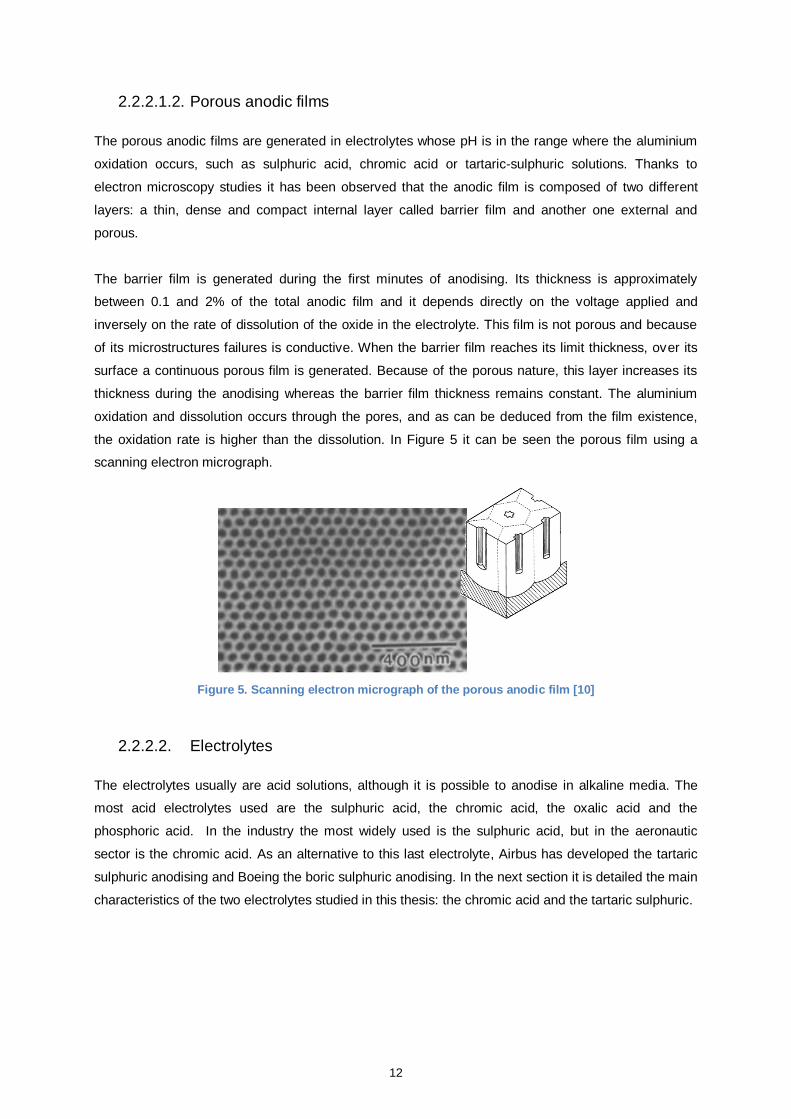
2.2.2.1.2. Porous anodic films ................................................................................... 12
2.2.2.2. Electrolytes .................................................................................................... 12
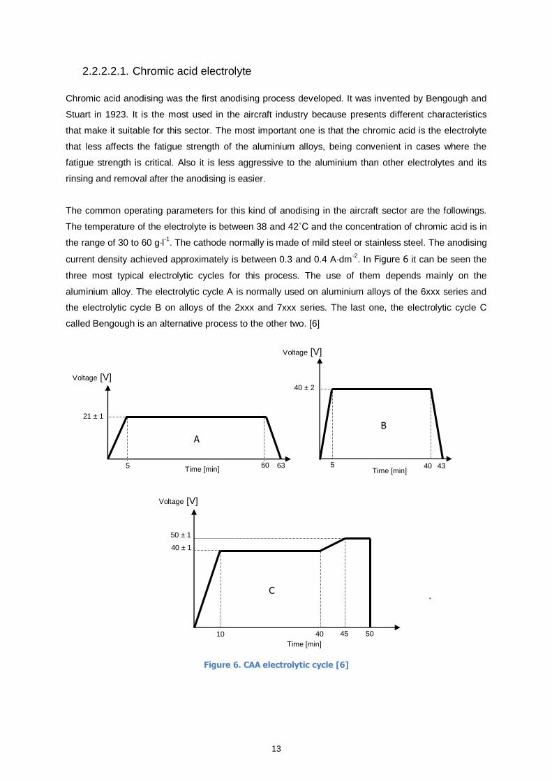
2.2.2.2.1. Chromic acid electrolyte ............................................................................. 13
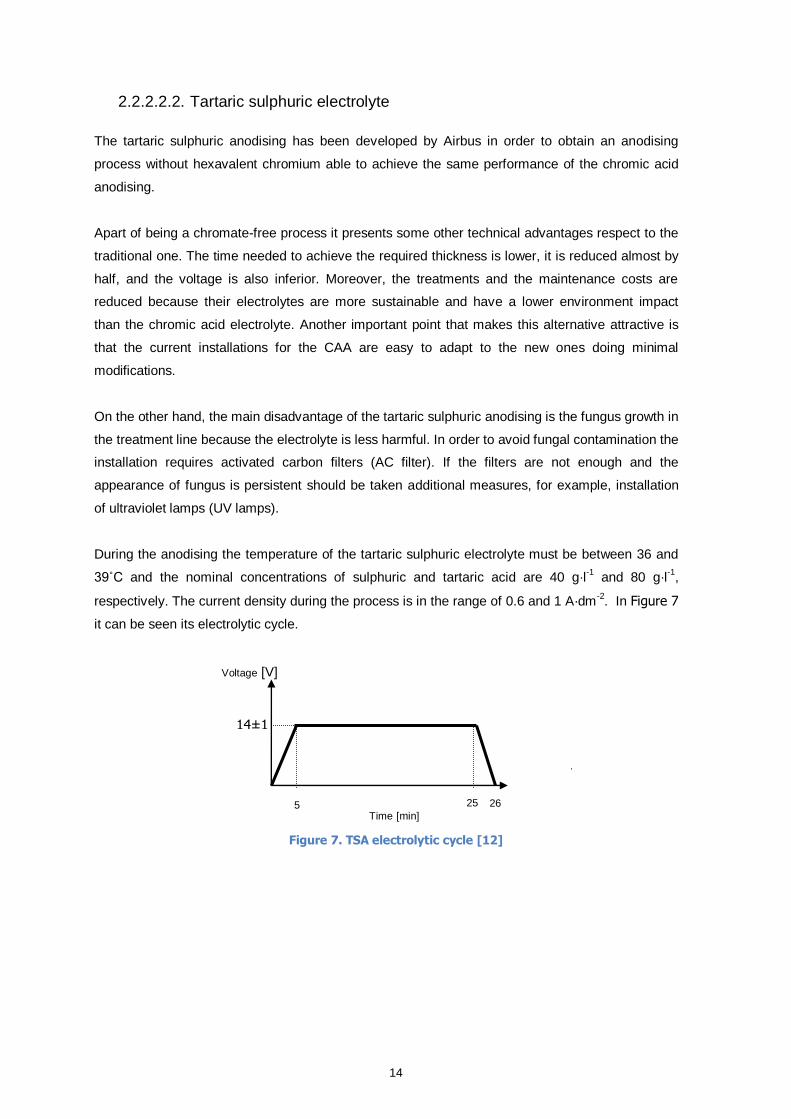
2.2.2.2.2. Tartaric sulphuric electrolyte ....................................................................... 14
3. Experimental procedure .................................................................................................. 17
3.1. Test specimen definition ............................................................................................. 17
3.1.1. Materials ........................................................................................................... 17
3.1.2. Dimensions ....................................................................................................... 18
3.2. Test specimen preparation process .............................................................................. 18
3.2.1. Test specimen pre-treatments ............................................................................. 20
3.2.1.1. Alkaline pre-degreasing .................................................................................. 20
3.2.1.2. Alkaline degreasing ........................................................................................ 21
3.2.1.3. Acid etching ................................................................................................... 21
3.2.2. Test specimen anodising .................................................................................... 23
3.2.2.1. TSA anodising installation .............................................................................. 23
3.2.2.2. Bath manufacture ........................................................................................... 25
3.2.2.3. Bath analysis ................................................................................................. 26
3.2.2.4. Anodising process .......................................................................................... 29
3.2.3. Test specimen post-treatments ............................................................................ 30
3.2.3.1. Sealing with hot demineralised water ................................................................ 30
3.2.3.2. Sealing with Bonderite® M-CR 1200S Aero ...................................................... 30
3.2.3.3. Sealing with potassium dichromate ................................................................... 31
3.2.3.4. Paint ............................................................................................................. 31
3.2.3.4.1. Primer ...................................................................................................... 31
3.2.3.4.2. Topcoat.................................................................................................... 32
3.3. Quality tests .............................................................................................................. 32
3.3.1. Coating thickness .............................................................................................. 32
3.3.1.1. Scope ........................................................................................................... 32
3.3.1.2. Fundamentals ................................................................................................ 32
3.3.1.3. Methodology .................................................................................................. 33
3.3.1.4. Coating weight .................................................................................................. 34
3.3.1.5. Scope ........................................................................................................... 34
3.3.1.6. Methodology .................................................................................................. 34
3.3.2. Corrosion resistance .......................................................................................... 35
3.3.2.1. Scope ........................................................................................................... 35
3.3.2.2. Fundamentals ................................................................................................ 35
3.3.2.3. Methodology .................................................................................................. 35
3.3.3. Paint adhesion .................................................................................................. 37
3.3.3.1. Scope ........................................................................................................... 37
3.3.3.2. Methodology .................................................................................................. 37
3.3.3.2.1. Dry adhesion test ...................................................................................... 37
3.3.3.2.2. Wet adhesion test...................................................................................... 38
3.3.4. Dye spot test ..................................................................................................... 39
3.3.4.1. Scope ........................................................................................................... 39
3.3.4.2. Fundamentals ................................................................................................ 39
3.3.4.3. Methodology .................................................................................................. 39
3.3.5. Dye spot test with prior acid treatment .................................................................. 40
3.3.5.1. Scope ........................................................................................................... 40
3.3.5.2. Fundamentals ................................................................................................ 40
3.3.5.3. Methodology .................................................................................................. 40
4. Results ........................................................................................................................... 41
4.1. Quality of the TSA anodic film ...................................................................................... 41
4.1.1. TSA coating thickness ........................................................................................ 42
4.1.2. TSA coating weight ............................................................................................ 43
4.1.3. TSA coating corrosion resistance ......................................................................... 45
4.1.4. TSA coating degree of sealing ............................................................................. 47
4.2. Quality of the post-treatments ...................................................................................... 49
4.2.1. Post-treatments corrosion resistance.................................................................... 49
4.2.1.1. Sealing with potassium dichromate ................................................................... 49
4.2.1.2. Sealing with Bonderite® M-CR 1200S Aero ....................................................... 51
4.2.2. Post-treatments dye spot resistance..................................................................... 55
4.2.2.1. Sealing with potassium dichromate ................................................................... 55
4.2.3. Paint adhesion .................................................................................................. 57
4.2.3.1. Dry paint adhesion test ................................................................................... 57
4.2.3.2. Wet paint adhesion test .................................................................................. 60
5. Conclusions ................................................................................................................... 63
6. Bibliography ................................................................................................................... 64
LIST OF FIGURES
Figure 1. Chromate applications in the aviation sector [5] ............................................................... 4
Figure 2. Airbus A340 materials [wt.%] [9] .................................................................................... 6
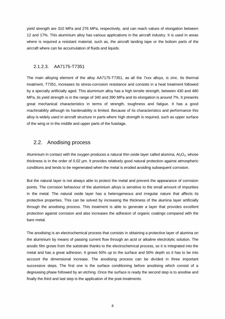
Figure 3. Electrochemical cell ................................................................................................... 10
Figure 4. Anodic film structure: (A) Barrier anodic film, (B) Porous anodic film [10] .......................... 11
Figure 5. Scanning electron micrograph of the porous anodic film [10] ........................................... 12
Figure 6. CAA electrolytic cycle [6] ............................................................................................ 13
Figure 7. TSA electrolytic cycle [12] ........................................................................................... 14
Figure 8. OGMA's facilities ........................................................................................................ 17
Figure 9. TSA anodising process .............................................................................................. 19
Figure 10. Bonderite® Smutgo NCB bath ................................................................................... 22
Figure 11. TSA anodising bath.................................................................................................. 24
Figure 12. Total acid titration .................................................................................................... 27
Figure 13. Sulphuric acid titration .............................................................................................. 28
Figure 14. TSA electrolytic cycle ............................................................................................... 29
Figure 15. Scheme of the eddy current generation on the test specimens ...................................... 33
Figure 16. Coating thickness gauge, Elcometer 355 .................................................................... 33
Figure 17. Salt spray chamber Ascott S1000t and NaCl solution tank ............................................ 36
Figure 18. Supports of the spray salt chamber ............................................................................ 36
Figure 19. Erichsen Multi Cross Cutter Model 295 ....................................................................... 37
Figure 20. Positioning of adhesive tape ..................................................................................... 38
Figure 21. Application of the Sanodal G on the samples: (I) Alloy 7175, (II) Alloy 2024 and (III) Alloy
6061 ...................................................................................................................................... 39
Figure 22. Sealing with hot water corrosion test: (a) Alloy 7175 etching with Bonderite® Smutgo NCB,
(b) Alloy 7175 etching with the first bath, (c) Alloy 6061 etching with Bonderite® Smutgo NCB, (d)
Alloy 6061 etching with the first bath, (e) Alloy 2024 etching with Bonderite® Smutgo NCB and (f) Alloy
2024 etching with the first bath ................................................................................................. 45
Figure 23. Sealing with hot water corrosion test repetition: (g) Alloy 7175, (h) Alloy 6061 and (i) Alloy
2024 ...................................................................................................................................... 46
Figure 24. Sealing with hot water dye spot test: (j) Alloy 2024 etching with Bonderite® Smutgo NCB,
(k) Alloy 2024 etching with the first bath, (l) Alloy 7175 etching with Bonderite® Smutgo NCB, (m) Alloy
7175 etching with the first bath, (n) Alloy 6061 etching with Bonderite® Smutgo NCB and (o) Alloy
6061 etching with the first bath ................................................................................................. 48
Figure 25. Sealing with hot water dye spot test expansion ............................................................ 48
Figure 26. Potassium dichromate corrosion test with etching bath 1: (A) Alloy 2024, (B) Alloy 7175 and
(C) Alloy 6061......................................................................................................................... 50
Figure 27. Potassium dichromate corrosion test with etching bath 2: (D) Alloy 2024, (E) Alloy 7175 and
(F) Alloy 6061 ......................................................................................................................... 50
Figure 28. Bonderite® 1200S corrosion test with etching bath 1: (G) Alloy 2024, (H) Alloy 7175 and (I)
Alloy 6061 .............................................................................................................................. 51
Figure 29. Bonderite® 1200S corrosion test with etching bath 2: (J) Alloy 2024, (K) Alloy 7175 and (L)
Alloy 6061 .............................................................................................................................. 52
Figure 30. Fastening methods: (a) titanium rack and (b) wire ........................................................ 53
Figure 31. Bonderite® 1200S corrosion test repetition on the Alloy 2024 ....................................... 54
Figure 32. Potassium dichromate dye spot test: (Q) Alloy 2024 etching with Bonderite® Smutgo NCB,
(R) Alloy 2024 etching with the first bath, (S) Alloy 7175 etching with Bonderite® Smutgo NCB, (T)
Alloy 7175 etching with the first bath, (U) Alloy 6061 etching with Bonderite® Smutgo NCB and (V)
Alloy 6061 etching with the first bath.......................................................................................... 56
Figure 33. Potassium dichromate dye spot test expansion ........................................................... 56
Figure 34. Alloy 2024 with primer after performing the dry paint adhesion test: (1) Bonderite® Smutgo
NCB etching bath, (2,3) First etching bath .................................................................................. 58
Figure 35. Alloy 7175 with primer after performing the dry paint adhesion test: (4) Bonderite® Smutgo
NCB etching bath, (5,6) First etching bath .................................................................................. 58
Figure 36. Alloy 6061 with primer after performing the dry paint adhesion test: (7) Bonderite® Smutgo
NCB etching bath, (8,9) First etching bath .................................................................................. 58
Figure 37. Alloy 2024 with primer plus top coat after performing the dry paint adhesion test: (10)
Bonderite® Smutgo NCB etching bath, (11,12) First etching bath ................................................. 59
Figure 38. Alloy 7175 with primer plus top coat after performing the dry paint adhesion test: (13)
Bonderite® Smutgo NCB etching bath, (14,15) First etching bath ................................................. 59
Figure 39. Alloy 6061 with primer plus top coat after performing the dry paint adhesion test: (16)
Bonderite® Smutgo NCB etching bath, (17,18) First etching bath ................................................. 59
Figure 40. Alloy 2024 with primer after performing the wet paint adhesion test: (19) Bonderite®
Smutgo NCB etching bath, (20,21) First etching bath .................................................................. 60
Figure 41. Alloy 7175 with primer after performing the wet paint adhesion test: (22) Bonderite®
Smutgo NCB etching bath, (23,24) First etching bath .................................................................. 60
Figure 42. Alloy 6061 with primer after performing the wet paint adhesion test: (25) Bonderite®
Smutgo NCB etching bath, (26,27) First etching bath .................................................................. 61
Figure 43. Alloy 2024 with primer plus top coat after performing the wet paint adhesion test: (28)
Bonderite® Smutgo NCB etching bath, (29,30) First etching bath ................................................. 61
Figure 44. Alloy 7175 with primer plus top coat after performing the wet paint adhesion test: (31)
Bonderite® Smutgo NCB etching bath, (32,33) First etching bath ................................................. 61
Figure 45. Alloy 6061 with primer plus top coat after performing the wet paint adhesion test: (34)
Bonderite® Smutgo NCB etching bath, (35,36) First etching bath ................................................. 62
LIST OF TABLES
Table 1. Characteristics of the CAA, BSAA and TSA processes [6] [7] [8] ........................................ 5
Table 2. Alloys' chemical composition [wt.%] [14] ........................................................................ 17
Table 3. Dimensions of the test specimens ................................................................................ 18
Table 4. Bonderite® Smutgo NCB composition ........................................................................... 22
Table 5. Comparison between the two etching baths ................................................................... 23
Table 6. Tank characteristics .................................................................................................... 25
Table 7. Components concentration .......................................................................................... 25
Table 8. Bonderite® 1200S composition .................................................................................... 30
Table 9. Stripping solution ........................................................................................................ 34
Table 10. TSA coating thickness ............................................................................................... 42
Table 11. CAA coating thickness of the alloy 7175 ...................................................................... 43
Table 12. CAA coating thickness of the alloy 2024 ...................................................................... 43
Table 13. TSA coating weight ................................................................................................... 44
Table 14. CAA coating weight ................................................................................................... 44
Table 15. Possible degrees of coloration .................................................................................... 47
Table 16. Possible degrees of detachment ................................................................................. 57
ABBREVIATIONS
AC Activated Carbon
BSAA Boric Sulphuric Acid Anodising
CAA Chromic Acid Anodising
CCC Chemical Conversion Coating
CMR Carcinogenic, Mutagenic or Toxic for Reproduction substances
ECHA European Chemicals Agency
ISO International Organization for Standardization
OAC Chromic Anodic Oxidation
PBT Persistent, Bioaccumulative and Toxic substances
REACH Registration, Evaluation, Authorisation and Restriction of Chemicals
SAA Sulphuric Acid Anodising
SVHC Substances of Very High Concern
TSA Tartaric Sulphuric Anodising
UV Ultraviolet
vPvB very Persistent and very Bioaccumulative substances
1
1. Introduction
1.1. Scope of the project
The main objective of this thesis is to study an alternative anodising process without hexavalent
chromium. The anodising process can be divided in three important successive steps. The first one is
the surface conditioning before anodising which consist of a degreasing phase followed by an acid
etching. Once the surface is ready the next step is to anodise and finally, when it is needed, different
post-treatments can be applied.
Nowadays, unfortunately, hexavalent chromium compounds are widely used in the anodising process
and they are present in the three stages. This thesis focuses on the analyses of chromium-free
alternatives for the surface conditioning and for the anodising.
The alternative product studied, as a substitute of the current acid etching bath with sodium
dichromate, is Bonderite® Smutgo NCB. It is analysed if the etching bath has influence on the final
results and it is verified if the new product without chromium compromise or not the effectiveness of
the anodising process.
The substitute bath analysed for the current Chromic Acid Anodising (CAA) is the Tartaric-Sulphuric
Anodising (TSA) developed by Airbus. It is studied if the TSA is capable of producing an anodic
coating film with the same resistance against corrosion and paint adhesion as the current CAA.
It is compared the thickness, the coating weight, the corrosion resistance and the loss of the
absorption power achieved by the TSA anodic film with those obtained with the CAA, to see if the first
process is a really good substitute for the second one.
It is also studied the compatibility of the TSA anodic film with various current post-treatments. It is
tested three different sealings: with hot water, with potassium dichromate and with the chemical
conversion coating Bonderite® M-CR 1200S Aero. On samples without sealing, it is checked the
compatibility of an epoxy primer and a polyurethane topcoat in use by Airbus.
In order to verify if there is a significant difference between the performances obtained on different
aluminium alloys, or otherwise, if the results obtained are similar regardless the composition and the
thermal treatment of them, all the tests were performed on three different ones.
The three aluminium alloys chosen are widely used in aeronautic applications and they are
representative of the 2xxx, 7xxx and 6xxx series, specifically, they are the AA2024-T3, AA7175-
T7351 and AA6061-T6.
2
1.2. State of art
1.2.1. Chromium
Chromium is a lustrous, brittle and very hard transition metal whose symbol is Cr. It is a good
conductor of electricity and heat, takes a high polish and has a good resistance against tarnishing and
corrosion. Its melting and boiling points are high. Its elemental state is difficult to find in the
environmental but its compounds are present in the nature and it can also be mined as chromite, its
most abundant mineral.
The health risks related to the exposure to chromium are dependent on its oxidation state. Chromium
has a large number of them. The trivalent and the hexavalent forms are the most frequently found in
its compounds, whereas +5, +4, +2 or lower oxidation states are more rare to observe.
The trivalent compounds are not considered a health hazard. Different studies have been conducted
but they could not find enough evidences to prove that the trivalent chromium is carcinogenic [1].
Although in large amounts it can cause nose and mouth irritations and even skin rashes.
In contrast, the hexavalent chromium is a toxic and carcinogenic substance which can cause serious
health problems. Exposure to it can produce respiratory problems, such as nosebleeds, nose irritation
and lung cancer; in contact with the skin it can cause rashes, irritation, dermatitis and ulceration; if it is
ingested produces upset stomachs, weakened immune systems, kidney and liver damage, alteration
of genetic material; and even can cause death if the exposure is prolonged. [2]
Because of the health and the environment risks that the exposure to hexavalent chromium involves,
progressively restrictions and rigorous controls have been imposed in the industries which use it in
their processes.
1.2.2. REACH regulation
REACH is a European regulation for the Registration, Evaluation, Authorisation and Restriction of
Chemicals. Its main objective is to provide protection against healthy and environmental risks that can
be produced by some chemicals.
All the companies and industries have to prove to ECHA (European Chemicals Agency) that they are
able to handle the risks related to the substances they use. When the hazards cannot be managed
ECHA can restrict them in different ways and the most dangerous substances should be substituted
with less harmful ones.
3
When a substance is considered to be hazardous it is incorporated into the list of Substances of Very
High Concern (SVHC) [3]. They can be divided in three big groups depending on their harmful
properties: Carcinogenic, Mutagenic or Toxic for Reproduction (CMR substances); Persistent,
Bioaccumulative and Toxic (PBT substances); or very Persistent and very Bioaccumulative (vPvB
substances). Once they are incorporated into this list the companies that use them must research and
develop sustainable alternatives because they must be removed from the production in the near
future.
Chromium hexavalent compounds were considered to be CMR substances and they were added in
the SVHC list on 2010. In order not to affect the industry negatively and to ensure a progressively
replaced of them, they were incorporated in the authorization list with a sunset date of 2017. These
hexavalent compounds are: chromium trioxide and their acids and oligomers, such as chromic acid
and dichromic acid; sodium dichromate; potassium dichromate; ammonium dichromate; potassium
chromate and sodium chromate. [4]
Because of this regulation, there is the need to search and analyse new alternatives processes
without chromium hexavalent compounds able to give the some performance of the current ones. It
affects many industries, but especially the aeronautic sector, where the anticorrosive properties of
these compounds are critical.
1.2.3. Chromates in the aircraft industry
Hexavalent chromium compounds, also known as Chromates, have been widely used in the aircraft
industry during the last decades. Their most important applications in this sector are the protection of
metallic surfaces thanks to their high corrosion resistance.
Chromates can be classified into three different groups depending on their applications: surface
treatment processes, paint applications and electric and electronic uses. The most important are in the
first and the second group.
The first group, surface treatments, involves processes such as: Chromic Acid Anodising (CAA);
Chemical Conversion Coatings (CCC), like Bonderite® M-CR 1200S Aero; hard chrome plating; or
acid etching products like sodium dichromate.
The second group includes all the processes related with paint applications, such as: external and
internal paints, like different primers and topcoats; bonding primers; or sealants.
As it can be seen in Figure 1, the surface treatments and the paint process are the applications with
the highest percentage of chromates. Only the CAA represents a 33% of total chromates used in the
aeronautic sector, while the external paints and the basic primers represents a 31% each one. The
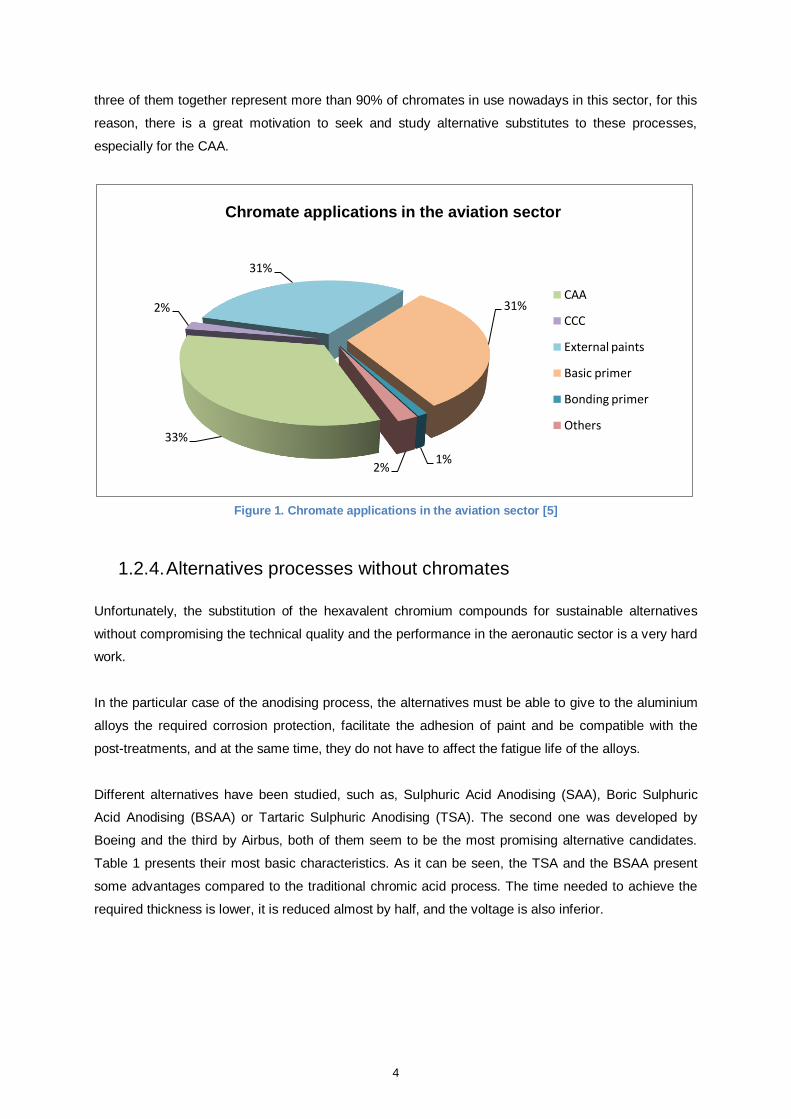
4
three of them together represent more than 90% of chromates in use nowadays in this sector, for this
reason, there is a great motivation to seek and study alternative substitutes to these processes,
especially for the CAA.
Figure 1. Chromate applications in the aviation sector [5]
1.2.4. Alternatives processes without chromates
Unfortunately, the substitution of the hexavalent chromium compounds for sustainable alternatives
without compromising the technical quality and the performance in the aeronautic sector is a very hard
work.
In the particular case of the anodising process, the alternatives must be able to give to the aluminium
alloys the required corrosion protection, facilitate the adhesion of paint and be compatible with the
post-treatments, and at the same time, they do not have to affect the fatigue life of the alloys.
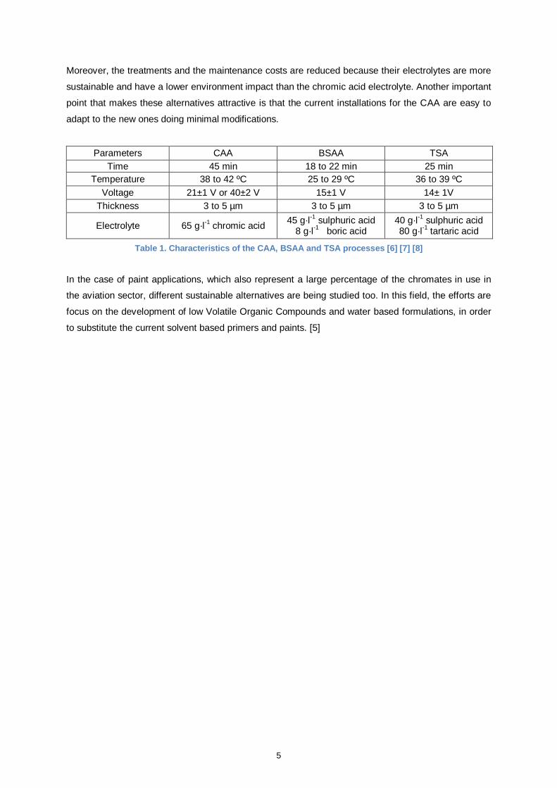
Different alternatives have been studied, such as, Sulphuric Acid Anodising (SAA), Boric Sulphuric
Acid Anodising (BSAA) or Tartaric Sulphuric Anodising (TSA). The second one was developed by
Boeing and the third by Airbus, both of them seem to be the most promising alternative candidates.
Table 1 presents their most basic characteristics. As it can be seen, the TSA and the BSAA present
some advantages compared to the traditional chromic acid process. The time needed to achieve the
required thickness is lower, it is reduced almost by half, and the voltage is also inferior.
33%
2%
31%
31%
1% 2%
Chromate applications in the aviation sector
CAA
CCC
External paints
Basic primer
Bonding primer
Others
5
Moreover, the treatments and the maintenance costs are reduced because their electrolytes are more
sustainable and have a lower environment impact than the chromic acid electrolyte. Another important
point that makes these alternatives attractive is that the current installations for the CAA are easy to
adapt to the new ones doing minimal modifications.
Parameters CAA BSAA TSA
Time 45 min 18 to 22 min 25 min
Temperature 38 to 42 ºC 25 to 29 ºC 36 to 39 ºC
Voltage 21±1 V or 40±2 V 15±1 V 14± 1V
Thickness 3 to 5 µm 3 to 5 µm 3 to 5 µm
Electrolyte 65 g·l-1
chromic acid 45 g·l
-1 sulphuric acid
8 g·l-1 boric acid
40 g·l-1
sulphuric acid 80 g·l
-1 tartaric acid
Table 1. Characteristics of the CAA, BSAA and TSA processes [6] [7] [8]
In the case of paint applications, which also represent a large percentage of the chromates in use in
the aviation sector, different sustainable alternatives are being studied too. In this field, the efforts are
focus on the development of low Volatile Organic Compounds and water based formulations, in order
to substitute the current solvent based primers and paints. [5]
6
2. Theoretical review
2.1. Aluminium and its alloys
2.1.1. Aluminium
Aluminium is the third most common element found in the earth’s crust. Due to its reactivity, it is
usually found combined with other elements such as iron, oxygen or silicon. The aluminium as metal is
obtained from the bauxite ore using an economical procedure. It consists in obtaining alumina using
the Bayer process with sodium hydroxide, followed by the alumina reduction to aluminium metal by
means of electrolysis.
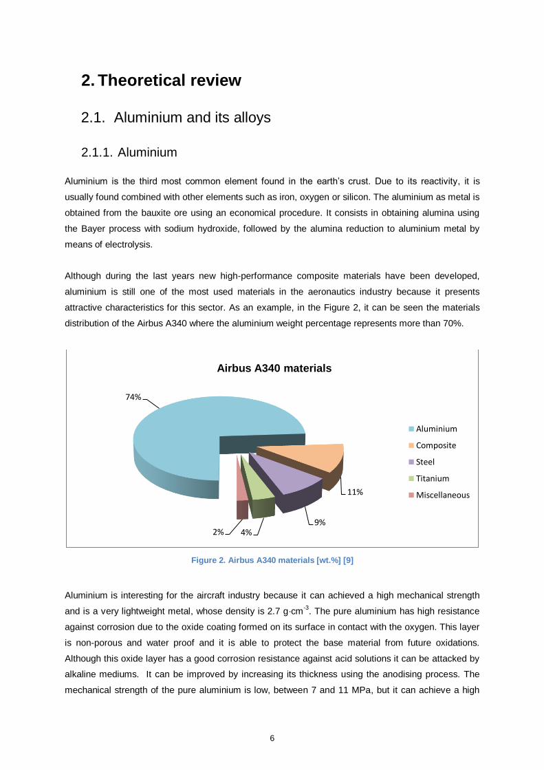
Although during the last years new high-performance composite materials have been developed,
aluminium is still one of the most used materials in the aeronautics industry because it presents
attractive characteristics for this sector. As an example, in the Figure 2, it can be seen the materials
distribution of the Airbus A340 where the aluminium weight percentage represents more than 70%.
Figure 2. Airbus A340 materials [wt.%] [9]
Aluminium is interesting for the aircraft industry because it can achieved a high mechanical strength
and is a very lightweight metal, whose density is 2.7 g·cm-3
. The pure aluminium has high resistance
against corrosion due to the oxide coating formed on its surface in contact with the oxygen. This layer
is non-porous and water proof and it is able to protect the base material from future oxidations.
Although this oxide layer has a good corrosion resistance against acid solutions it can be attacked by
alkaline mediums. It can be improved by increasing its thickness using the anodising process. The
mechanical strength of the pure aluminium is low, between 7 and 11 MPa, but it can achieve a high
74%
11%
9% 4% 2%
Airbus A340 materials
Aluminium
Composite
Steel
Titanium
Miscellaneous
7
one, around 690 MPa, by means of heat treatments and alloying. However, most of these alloying
elements which increase its mechanical strength affect negativity its corrosion resistance. For this
reason, it is necessary to apply surface treatments in order to achieve a good protection. [10]
2.1.2. Aluminium alloys
As it mentioned above, the pure aluminium has little interest for structural uses because it presents a
low strength resistance. For this reason, in the industry is not used in its pure form but combined with
alloying elements in order to improve its performance. The most common ones are silicon,
magnesium, manganese, zinc and copper. Each one of them improves different specific properties.
Silicon increases its mechanical strength and ductility and reduces the melting point. Magnesium as
alloying reduces the melting point too and increments its corrosion resistance. Copper provides a high
strength but it worsens its corrosion resistance, ductility and weldability. Manganese increases its
strength with the advantage that does not affect its resistance against corrosion. And finally zinc gives
a great mechanical strength and enables hot and cold precipitation hardening.
The aluminium alloys studied in this thesis are three: the AA2024-T3, the AA6061-T6 and the AA7175-
T7351.
2.1.2.1. AA2024-T3
The AA2024-T3 is an aluminium alloy whose main alloying element is cooper, as all the alloys of the
2xxx series. Its thermal treatment, T3, consists in a heat treatment followed by cold work and a
naturally aged to a substantially stable condition. It has an ultimate tensile strength between 400 and
425 MPa, its yield strength is around 270 MPa and its elongation is in the range of 10 and 15%. It is
one of the most used alloys in aircraft applications because of its high strength to weight ratio, its good
resistance to fatigue crack growth along with high fracture toughness. However it presents a low
weldability and an average machinability. It has a poor corrosion resistance, because of copper, and
normally it is clad with aluminium or aluminium alloy with zinc in order to improve it, although, the
fatigue resistance can be negatively affected. As said above, it is one of the most alloys used in the
aircraft structure and in bottom parts of the wing.
2.1.2.2. AA6061-T6
The main alloying elements of the series 6xxx, such as AA6061-T6, are magnesium and silicon. The
thermal treatment T6 gives to the alloy dimensional stability and consists in a heat treatment followed
by an artificially age. It presents good mechanical properties and good resistance against corrosion. It
can achieve a good finishing and has a high weldability. Its ultimate tensile strength and its tensile
8
yield strength are 310 MPa and 276 MPa, respectively, and can reach values of elongation between
12 and 17%. This aluminium alloy has various applications in the aircraft industry. It is used in areas
where is required a resistant material, such as, the aircraft landing tape or the bottom parts of the
aircraft where can be accumulation of fluids and liquids.
2.1.2.3. AA7175-T7351
The main alloying element of the alloy AA7175-T7351, as all the 7xxx alloys, is zinc. Its thermal
treatment, T7351, increases its stress-corrosion resistance and consists in a heat treatment followed
by a specially artificially aged. This aluminium alloy has a high tensile strength, between 430 and 480
MPa, its yield strength is in the range of 340 and 390 MPa and its elongation is around 7%. It presents
great mechanical characteristics in terms of strength, toughness and fatigue. It has a good
machinability although its hardenability is limited. Because of its characteristics and performance this
alloy is widely used in aircraft structure in parts where high strength is required, such as upper surface
of the wing or in the middle and upper parts of the fuselage.
2.2. Anodising process
Aluminium in contact with the oxygen produces a natural thin oxide layer called alumina, Al2O3, whose
thickness is in the order of 0.02 µm. It provides relatively good natural protection against atmospheric
conditions and tends to be regenerated when the metal is eroded avoiding subsequent corrosion.
But the natural layer is not always able to protect the metal and prevent the appearance of corrosion
points. The corrosion behaviour of the aluminium alloys is sensitive to the small amount of impurities
in the metal. The natural oxide layer has a heterogeneous and irregular nature that affects its
protective properties. This can be solved by increasing the thickness of the alumina layer artificially
through the anodising process. This treatment is able to generate a layer that provides excellent
protection against corrosion and also increases the adhesion of organic coatings compared with the
bare metal.
The anodising is an electrochemical process that consists in obtaining a protective layer of alumina on
the aluminium by means of passing current flow through an acid or alkaline electrolytic solution. The
anodic film grows from the substrate thanks to the electrochemical process, so it is integrated into the
metal and has a great adhesion. It grows 50% up to the surface and 50% depth so it has to be into
account the dimensional increase. The anodising process can be divided in three important
successive steps. The first one is the surface conditioning before anodising which consist of a
degreasing phase followed by an etching. Once the surface is ready the second step is to anodise and
finally the third and last step is the application of the post-treatments.
9
2.2.1. Pre-treatments
The surface preparation is really important and cannot be underestimated, without a good conditioning
the performance and the quality of the rest of the subsequent processes could be affected and the
required results could not be achieved.
2.2.1.1. Degreasing and cleaning
Degreasing and cleaning are the first processes before performing the rest of the surface treatments.
The main objective of them is to remove any traces of dirt that can be deposited on the metal surface
during the manipulation or transportation of the material. The main dirties found on the aluminium
surface are: marking inks, grease, lube oils, polishing residues, finger marks, metal chips, welding or
brazing fluids. This cleaning is necessary in order to achieve a good anodic reaction and to get a
uniform aluminium oxide layer.
The most current methods used are the alkaline degreasing products. They are the substitutes of the
vapour degreasing methods based on chlorinated and fluorinated solvents which are obsolete due to
ecological concerns. However, a part of the alkaline degreasing products, there are ultrasonic cleaning
methods, although they are normally used in particular cases when the other ones are not suitable.
Nowadays, there are a lot of alkaline degreasing products in the market. Their main compounds are
usually sodium hydroxide, corrosion inhibitors and wetting agents. They have to be appropriated to the
metals and their attack to them must be minimized and controlled. In the case of aluminium their pH
should remain between 9 and 11. They should have high rinsing performance, high solubility, good
wetting properties and a great emulsifying power.
Ultrasonic cleaning methods require expensive equipment and they are more suitable when the parts
to be cleaned are small. They are used when the cleaning is difficult and the immersion methods are
not good enough. [11]
2.2.1.2. Etching
The controlled etching of the surface is a critical step in the process. It consists in removing the
aluminium oxides that may be present on the surface in different quantities and forms and replaced
them by a thin and uniform coating in order to provide a uniform base for the anodising. There are two
different types of etchings: the alkaline etching and the acid etching. Their rate of etching depends on
the concentration of the product and on the operating temperature.
10
The alkaline etching bath is normally composed by an aqueous solution of sodium hydroxide, with a
concentration of 5 to 10% and an operating temperature between 40 and 50 ºC. It is the most
economical etching method. The drawback is that it requires another subsequent process with nitric
acid, especially in the case of aluminium alloys with copper, in order to remove the insoluble products
generating during the alkaline etching. For this reason, it is rarely used in the aviation sector.
The acid etching has been traditionally performed using a solution composed of sulphuric acid,
hydrofluoric acid and sodium dichromate at room temperature. This last component, like all hexavalent
chromium compounds, is considered hazardous and carcinogen. Because of the health concerns
about them, alternative products have been developed based on phosphoric and sulphuric acid
solutions. In the aeronautic sector the most new favourable formulations are composed by sulphuric
acid, ferric sulphate and acid nitric, for example, the Bonderite® Smutgo NCB studied in this thesis.
2.2.2. Anodising
As explained above, the anodising consists in the oxidation of the aluminium surface: the aluminium
metal is converted to aluminium oxide or alumina. Figure 14 shows the schematic of the device
needed to perform the anodising. It consists of two electrodes connected to a current rectifier and
immersed in an electrochemical cell containing an electrolyte. In order to control the intensity and the
voltage of the process, an ammeter is connected in series and a voltmeter in parallel. The aluminium
acts as an anode and it is where the oxidation occurs. The cathode, whose function is to close the
electrolyte circuit, is usually of steel or lead, although this last one has fallen into disuse. When the
electric current is applied to the system the electrons flow from the anode to the cathode leaving
cations on the aluminium alloy surface.
Figure 3. Electrochemical cell
Ammeter
Voltmeter
Anode Cathode
Electrolyte
11
If the electrolyte is an acid solution, the oxygen from the electrolytic dissociation of the water will react
with the cations of the anode in order to produce alumina on the surface of the alloy. The reactions
that take place are the followings:
Cathode: 6H+ +
6e
- → 3H2 (2.1)
Anode: Al → Al3+
+ 3e- (2.2)
2Al3+
+ 3H2O → Al2O3 + 6H+ (2.3)
Balance equation: 2Al + 3H2O → Al2O3 + 3H2 (2.4)
The conversion process of the aluminium is determined by the time and the electric current density of
the anodising, if these parameters increase the conversion increases too. The morphology and the
thickness of the anodic film also depend on the voltage, temperature and electrolyte composition.
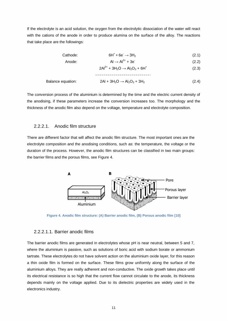
2.2.2.1. Anodic film structure
There are different factor that will affect the anodic film structure. The most important ones are the
electrolyte composition and the anodising conditions, such as: the temperature, the voltage or the
duration of the process. However, the anodic film structures can be classified in two main groups:
the barrier films and the porous films, see Figure 4.
Figure 4. Anodic film structure: (A) Barrier anodic film, (B) Porous anodic film [10]
2.2.2.1.1. Barrier anodic films
The barrier anodic films are generated in electrolytes whose pH is near neutral, between 5 and 7,
where the aluminium is passive, such as solutions of boric acid with sodium borate or ammonium
tartrate. These electrolytes do not have solvent action on the aluminium oxide layer, for this reason
a thin oxide film is formed on the surface. These films grow uniformly along the surface of the
aluminium alloys. They are really adherent and non-conductive. The oxide growth takes place until
its electrical resistance is so high that the current flow cannot circulate to the anode, its thickness
depends mainly on the voltage applied. Due to its dielectric properties are widely used in the
electronics industry.
Pore
Porous layer
Barrier layer
Aluminium
A B
Al2O3
12
2.2.2.1.2. Porous anodic films
The porous anodic films are generated in electrolytes whose pH is in the range where the aluminium
oxidation occurs, such as sulphuric acid, chromic acid or tartaric-sulphuric solutions. Thanks to
electron microscopy studies it has been observed that the anodic film is composed of two different
layers: a thin, dense and compact internal layer called barrier film and another one external and
porous.
The barrier film is generated during the first minutes of anodising. Its thickness is approximately
between 0.1 and 2% of the total anodic film and it depends directly on the voltage applied and
inversely on the rate of dissolution of the oxide in the electrolyte. This film is not porous and because
of its microstructures failures is conductive. When the barrier film reaches its limit thickness, over its
surface a continuous porous film is generated. Because of the porous nature, this layer increases its
thickness during the anodising whereas the barrier film thickness remains constant. The aluminium
oxidation and dissolution occurs through the pores, and as can be deduced from the film existence,
the oxidation rate is higher than the dissolution. In Figure 5 it can be seen the porous film using a
scanning electron micrograph.
Figure 5. Scanning electron micrograph of the porous anodic film [10]
2.2.2.2. Electrolytes
The electrolytes usually are acid solutions, although it is possible to anodise in alkaline media. The
most acid electrolytes used are the sulphuric acid, the chromic acid, the oxalic acid and the
phosphoric acid. In the industry the most widely used is the sulphuric acid, but in the aeronautic
sector is the chromic acid. As an alternative to this last electrolyte, Airbus has developed the tartaric
sulphuric anodising and Boeing the boric sulphuric anodising. In the next section it is detailed the main
characteristics of the two electrolytes studied in this thesis: the chromic acid and the tartaric sulphuric.
13
2.2.2.2.1. Chromic acid electrolyte
Chromic acid anodising was the first anodising process developed. It was invented by Bengough and
Stuart in 1923. It is the most used in the aircraft industry because presents different characteristics
that make it suitable for this sector. The most important one is that the chromic acid is the electrolyte
that less affects the fatigue strength of the aluminium alloys, being convenient in cases where the
fatigue strength is critical. Also it is less aggressive to the aluminium than other electrolytes and its
rinsing and removal after the anodising is easier.
The common operating parameters for this kind of anodising in the aircraft sector are the followings.
The temperature of the electrolyte is between 38 and 42˚C and the concentration of chromic acid is in
the range of 30 to 60 g·l-1
. The cathode normally is made of mild steel or stainless steel. The anodising
current density achieved approximately is between 0.3 and 0.4 A·dm-2
. In Figure 6 it can be seen the
three most typical electrolytic cycles for this process. The use of them depends mainly on the
aluminium alloy. The electrolytic cycle A is normally used on aluminium alloys of the 6xxx series and
the electrolytic cycle B on alloys of the 2xxx and 7xxx series. The last one, the electrolytic cycle C
called Bengough is an alternative process to the other two. [6]
Figure 6. CAA electrolytic cycle [6]
40
40 5 43 Time [min]
40 ± 2
Voltage [V]
5 60 63
Voltage [V]
21 ± 1
Time [min]
50 ± 1
40 ± 1
10 45 50
Voltage [V]
Time [min]
A
B
C
14
2.2.2.2.2. Tartaric sulphuric electrolyte
The tartaric sulphuric anodising has been developed by Airbus in order to obtain an anodising
process without hexavalent chromium able to achieve the same performance of the chromic acid
anodising.
Apart of being a chromate-free process it presents some other technical advantages respect to the
traditional one. The time needed to achieve the required thickness is lower, it is reduced almost by
half, and the voltage is also inferior. Moreover, the treatments and the maintenance costs are
reduced because their electrolytes are more sustainable and have a lower environment impact
than the chromic acid electrolyte. Another important point that makes this alternative attractive is
that the current installations for the CAA are easy to adapt to the new ones doing minimal
modifications.
On the other hand, the main disadvantage of the tartaric sulphuric anodising is the fungus growth in
the treatment line because the electrolyte is less harmful. In order to avoid fungal contamination the
installation requires activated carbon filters (AC filter). If the filters are not enough and the
appearance of fungus is persistent should be taken additional measures, for example, installation
of ultraviolet lamps (UV lamps).
During the anodising the temperature of the tartaric sulphuric electrolyte must be between 36 and
39˚C and the nominal concentrations of sulphuric and tartaric acid are 40 g·l-1
and 80 g·l-1
,
respectively. The current density during the process is in the range of 0.6 and 1 A·dm-2. In Figure 7
it can be seen its electrolytic cycle.
Figure 7. TSA electrolytic cycle [12]
14±1
Voltage [V]
5 Time [min]
25 26
15
2.2.3. Post-treatments
2.2.3.1. Sealing with hot deminieralised water
As mentioned above the anodic film obtained after the aluminium anodising is porous and has
absorbent properties, for this reason is not protective enough against corrosion. In order to improve
the properties of the anodic film, one possible post-treatment is sealing with demineralised water. It
consists in immersing the aluminum in hot demineralised water in order to hydrate the alumina and
close the porous structure. The aluminium oxide is converted into a stable layer called boehmite,
AlOOH. The reaction that takes place is the following:
Al2O3 + H2O → 2 AlOOH (2.5)
The conversion of aluminium oxide to boehmite involves an increase in volume able to close to
porous, accompanied by a significant decrease in electric capacity and a large increase of its electrical
resistance.
The sealing rate depends on the temperature of the demineralised water. The higher and most
efficient rate is achieved between 98 and 100˚C. Apart from the temperature, the sealing also depends
on the water pH which should be between 5 and 7 where the alumina is stable. The time needed to
obtain a good quality sealing varies according to the film thickness, the pore diameter and the specific
properties of the aluminium oxide. A time between 20 and 60 minutes is enough, for example, in the
case of the tartaric sulphuric anodising Airbus recommends a time of 40 minutes.
2.2.3.2. Chemical Conversion Coatings (CCC)
The chemical conversion coatings are protective and adherent layers whose main objective is to
improve the adhesion between the organic coating and the aluminium alloys surface. They also
provide protection against corrosion and are used as a treatment in areas where the anodic film is
damage or in parts where is difficult to get a good anodising of the surface because of their shape.
The chemical conversion coatings are based on oxidation-reduction reactions of different reagents
with the aluminium alloy surface. They can be divided in two main groups: phosphate conversion
coatings and chromate conversion coatings. In the aircraft industry is used the last group, mainly
the Bonderite® 1200S. Due to the health risks related with chromates new alternative products are
being studied, such as Bonderite® 5700, Nabutan STI/310 or Iridite NCP. [13]
16
2.2.3.3. Organic coatings
The organic coatings in aeronautical applications are composed by two layers, a primer and a
topcoat. Their main function is to protect the aluminium alloy of oxygen, ions and water. In case
that some agent was able to penetrate into the coating they must act as corrosion inhibitors too.
Between the metal and the organic coating is applied a conversion coating whose main functions
are to improve the adhesion between them and provide some corrosion resistance. The conversion
coating can be an anodic film or a chemical conversion coating.
The primers are applied directly on the conversion coating and their main function is to give
resistance against corrosion. Nowadays, they are chromate products and can have around a 25%
of chromate inhibitors. The most used is strontium dichromate. The topcoats protect of mechanical
damage and some of their components are UV absorbers in order to avoid coating
photodegradation.
17
3. Experimental procedure
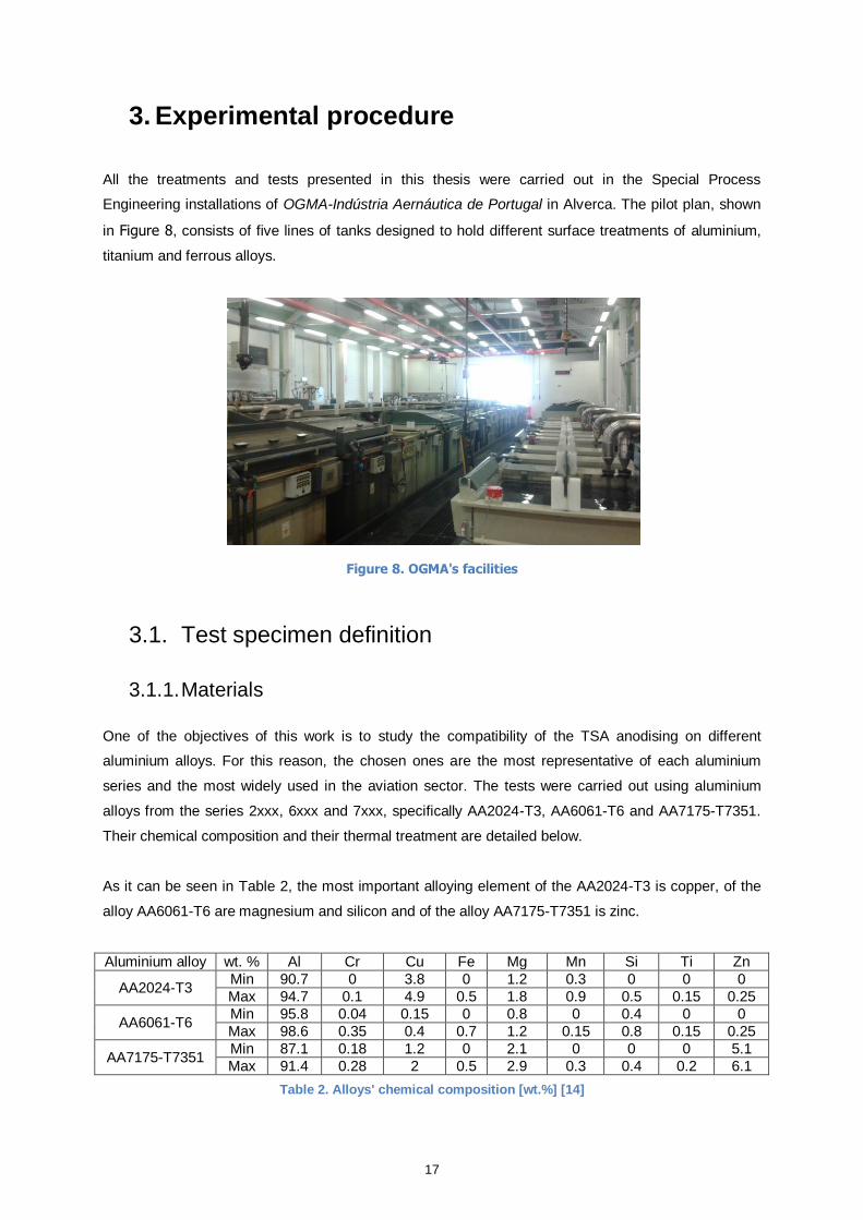
All the treatments and tests presented in this thesis were carried out in the Special Process
Engineering installations of OGMA-Indústria Aernáutica de Portugal in Alverca. The pilot plan, shown
in Figure 8, consists of five lines of tanks designed to hold different surface treatments of aluminium,
titanium and ferrous alloys.
Figure 8. OGMA's facilities
3.1. Test specimen definition
3.1.1. Materials
One of the objectives of this work is to study the compatibility of the TSA anodising on different
aluminium alloys. For this reason, the chosen ones are the most representative of each aluminium
series and the most widely used in the aviation sector. The tests were carried out using aluminium
alloys from the series 2xxx, 6xxx and 7xxx, specifically AA2024-T3, AA6061-T6 and AA7175-T7351.
Their chemical composition and their thermal treatment are detailed below.
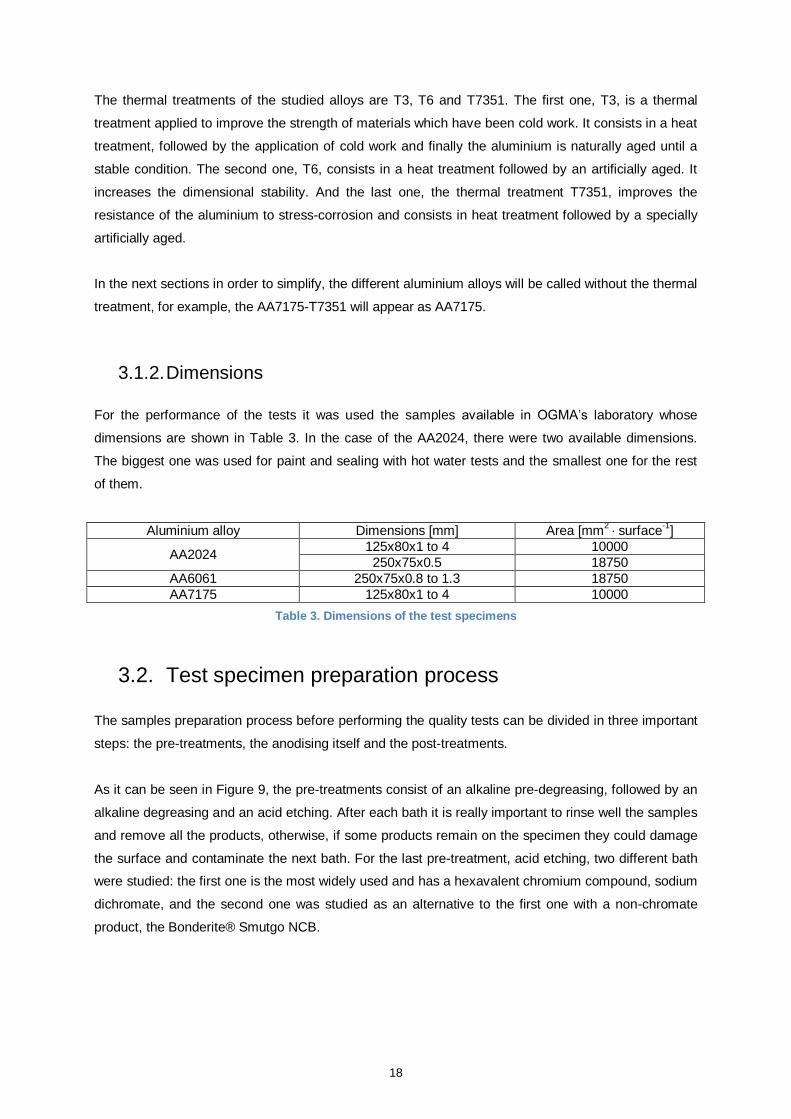
As it can be seen in Table 2, the most important alloying element of the AA2024-T3 is copper, of the
alloy AA6061-T6 are magnesium and silicon and of the alloy AA7175-T7351 is zinc.
Aluminium alloy wt. % Al Cr Cu Fe Mg Mn Si Ti Zn
AA2024-T3 Min 90.7 0 3.8 0 1.2 0.3 0 0 0
Max 94.7 0.1 4.9 0.5 1.8 0.9 0.5 0.15 0.25
AA6061-T6 Min 95.8 0.04 0.15 0 0.8 0 0.4 0 0
Max 98.6 0.35 0.4 0.7 1.2 0.15 0.8 0.15 0.25
AA7175-T7351 Min 87.1 0.18 1.2 0 2.1 0 0 0 5.1
Max 91.4 0.28 2 0.5 2.9 0.3 0.4 0.2 6.1
Table 2. Alloys' chemical composition [wt.%] [14]
18
The thermal treatments of the studied alloys are T3, T6 and T7351. The first one, T3, is a thermal
treatment applied to improve the strength of materials which have been cold work. It consists in a heat
treatment, followed by the application of cold work and finally the aluminium is naturally aged until a
stable condition. The second one, T6, consists in a heat treatment followed by an artificially aged. It
increases the dimensional stability. And the last one, the thermal treatment T7351, improves the
resistance of the aluminium to stress-corrosion and consists in heat treatment followed by a specially
artificially aged.
In the next sections in order to simplify, the different aluminium alloys will be called without the thermal
treatment, for example, the AA7175-T7351 will appear as AA7175.
3.1.2. Dimensions
For the performance of the tests it was used the samples available in OGMA’s laboratory whose
dimensions are shown in Table 3. In the case of the AA2024, there were two available dimensions.
The biggest one was used for paint and sealing with hot water tests and the smallest one for the rest
of them.
Aluminium alloy Dimensions [mm] Area [mm2 · surface
-1]
AA2024 125x80x1 to 4 10000
250x75x0.5 18750
AA6061 250x75x0.8 to 1.3 18750
AA7175 125x80x1 to 4 10000
Table 3. Dimensions of the test specimens
3.2. Test specimen preparation process
The samples preparation process before performing the quality tests can be divided in three important
steps: the pre-treatments, the anodising itself and the post-treatments.
As it can be seen in Figure 9, the pre-treatments consist of an alkaline pre-degreasing, followed by an
alkaline degreasing and an acid etching. After each bath it is really important to rinse well the samples
and remove all the products, otherwise, if some products remain on the specimen they could damage
the surface and contaminate the next bath. For the last pre-treatment, acid etching, two different bath
were studied: the first one is the most widely used and has a hexavalent chromium compound, sodium
dichromate, and the second one was studied as an alternative to the first one with a non-chromate
product, the Bonderite® Smutgo NCB.
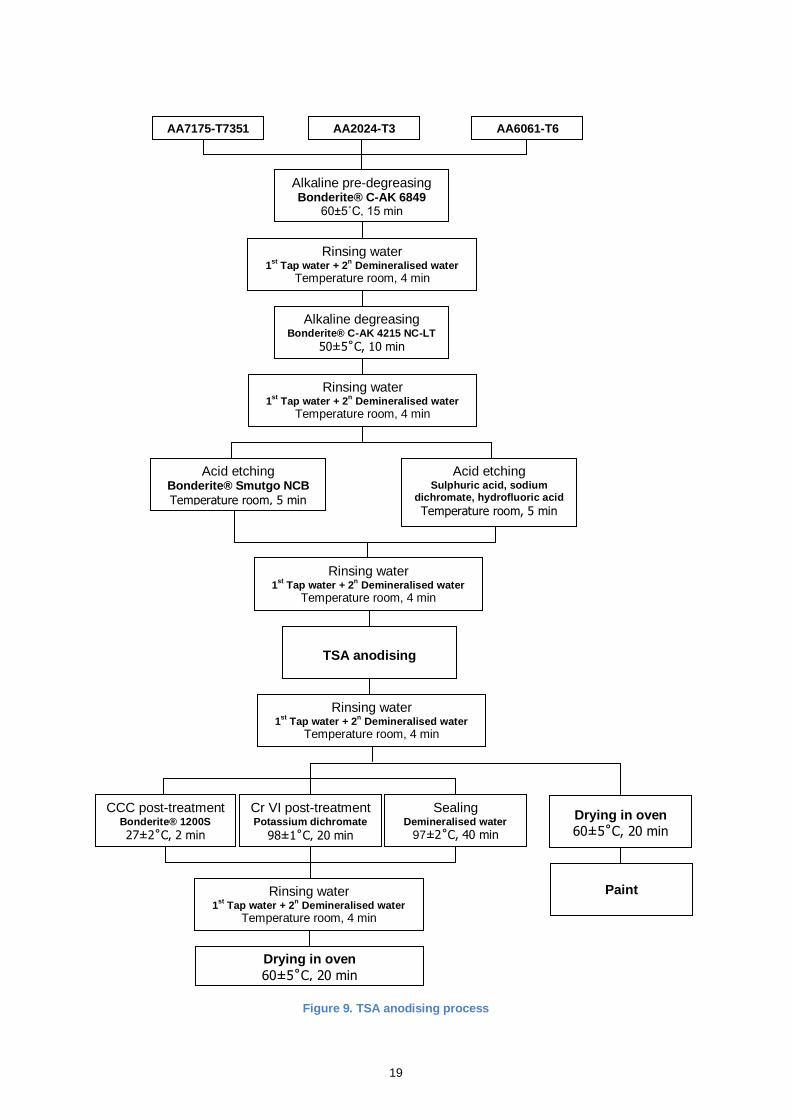
19
Figure 9. TSA anodising process
AA7175-T7351 AA2024-T3 AA6061-T6
Alkaline pre-degreasing Bonderite® C-AK 6849
60±5˚C, 15 min
Alkaline degreasing Bonderite® C-AK 4215 NC-LT
50±5˚C, 10 min
Rinsing water 1
st Tap water + 2
n Demineralised water
Temperature room, 4 min
Rinsing water 1
st Tap water + 2
n Demineralised water
Temperature room, 4 min
Drying in oven
60±5˚C, 20 min
Paint
TSA anodising
Acid etching Bonderite® Smutgo NCB
Temperature room, 5 min
Acid etching Sulphuric acid, sodium
dichromate, hydrofluoric acid Temperature room, 5 min
Rinsing water 1
st Tap water + 2
n Demineralised water
Temperature room, 4 min
Rinsing water 1
st Tap water + 2
n Demineralised water
Temperature room, 4 min
CCC post-treatment Bonderite® 1200S
27±2˚C, 2 min
Cr VI post-treatment Potassium dichromate
98±1˚C, 20 min
Sealing Demineralised water
97±2˚C, 40 min
Drying in oven
60±5˚C, 20 min
Rinsing water 1
st Tap water + 2
n Demineralised water
Temperature room, 4 min
20
Once the pre-treatments have been applied and the samples have been rinsed, they are ready to be
anodised. After the anodising and the proper rinsing, the post-treatments can be applied. It was
studied the compatibility of three different current sealings: with demineralised hot water, with
Bonderite® 1200S and with potassium dichromate. After their application the samples finally are
rinsed and dried in oven.
The process followed in the case of the painted samples is slightly different. After the anodising and
the proper rinsing the specimens are immediately dried. And they are painted within 24 hours after the
anodising treatment.
3.2.1. Test specimen pre-treatments
The surface preparation before anodising is really important in the process because it directly affects
the anodic film quality and the effectiveness of the post-treatments. In this case it consists of three
successive steps: an alkaline pre-degreasing, an alkaline degreasing and an acid etching.
In the following sections there is a description of each step, explaining their applications and the
products used.
3.2.1.1. Alkaline pre-degreasing
The first step is to immerse the test specimen an alkaline pre-degreasing bath. Its main goal is remove
marking inks, grease and lube oils from the surface.
The product that was used is the aqueous alkaline degreaser Bonderite® C-AK 6849 AERO
manufactured by Henkel which is a free chromate product. For the preparation of the immersion bath it
is necessary to add Bonderite® 6849 at 10 to 20% by volume to water. Its operating temperature is
from 55˚ to 70˚C, for this reason the tank has a temperature control system that keeps it at 60±5˚C.
The bath is also equipped with an air agitation system and an oil and grease removal system for
prolonging its service life.
The immersion time depends on the amount of contaminants on the aluminium alloy surface. It usually
is between 15 and 30 minutes. The surface of the test specimens is relatively clean, for this reason
they were immersed 15 minutes.
After the immersion in the pre-degreasing bath the test specimens have to be rinsed at least for 3
minutes. In this particular case, they were immersed in two subsequent baths. The first one with tap
water for 2 minutes and the second one with demineralised water for 2 more minutes to ensure that
the entire product was removed.
21
The next step after rinsing the specimens is to immerse them in the alkaline degreasing bath. It is
important to keep the samples always wet along the process and do not let them dry to prevent
contamination.
3.2.1.2. Alkaline degreasing
After the pre-degreasing, the test specimens were immersed in the alkaline degreasing bath. The
product used was Bonderite® C-AK 4215 NC-LT manufactured by Henkel. It is an aqueous free
chromate solution which attacks the aluminium slightly. The main function of this alkaline cleaner is to
remove all grease and oils that may be left after the first bath.
The product concentration in the bath should be between 45 and 60 g·l-1. Its operating temperature is
from 45 to 55˚C, for this reason the tank has a temperature control system that guarantees this range.
It is also equipped with an air stirring system and an oil and grease removal. The immersion time in
the bath should be between 5 and 10 minutes. In this case, an immersion of 10 minutes was enough
to provide a good superficial cleaning.
As in the previous step, after the degreasing bath the samples were rinsed first in tap water and then
with demineralised water following the same procedure.
3.2.1.3. Acid etching
Apart from removing the oils and grease, it is necessary to remove the oxides present on the surface
to provide a uniform base for the next step, the anodising. This is needed because in addition to
contaminants, aluminium oxides may be present on the surface in different quantities and forms.
These oxides have to be removed and replaced by a thin and uniform oxide coating. This is reached
by a controlled acid etching of the surface.
The most widely bath for this process is a solution composed of sulphuric acid, hydrofluoric acid and
sodium dichromate. This last component, like all hexavalent chromium compounds, is considered
hazardous and carcinogen. As the main objective of this thesis is the development a chromate VI-free
process, it was studied an alternative product: the Bonderite® Smutgo NCB.
All the tests were performed with the two products to verify that the use of the new one does not
compromise the effectiveness of the anodising and to confirm that the same results are achieved with
both of them, in order to demonstrate that the Bonderite® Smutgo NCB is a good non-chromate
substitute.
22
The nominal concentration in the first bath is 79 g·l-1
of sulphuric acid, 42 g·l-1
of sodium dichromate
and 1.13 g·l-1
of hydrofluoric acid. It is also necessary to control the amount of Cu and Al to ensure
that their levels in the bath are below 0.20 g·l-1
and 17.22 g·l-1
, respectively. It works at room
temperature, so it does not need any temperature control system. However, it requires a stirring
system. The immersion time of the samples in this bath was 5 minutes.
The Bonderite® Smutgo NCB is a dark brown liquid and is formulated to deoxidize and desmut
aluminium alloys, like the first bath. Its operating temperature is between 10 and 50ºC. It requires a
stirring system. According to the manufacture, the concentration in the bath should be between 22 to
28% of product in water. Its nominal etch rates are in the range of 2.54 to 22.86 µm/surface/hr. The
immersion time, as in the first bath, was 5 minutes. In Table 4 it can be seen its composition.
Component Percentage [%]
Ferric sulphate 30-60
Nitric acid 5-10
Sodium hydrogendiflouride 1-5
Sulphuric acid 0.1-1
Table 4. Bonderite® Smutgo NCB composition
All the previous baths are part of the production line, so it was not necessary to manufacture them. But
the Bonderite® Smutgo NCB is a new product. For this reason, in order to perform the tests a small
bath, large enough for the immersion of the tests specimens, was manufactured. As shown in Figure
10.
Figure 10. Bonderite® Smutgo NCB bath
23
In Table 5, there is a comparison of the most important characteristics of each bath. Their etching
rates on the AA2024 were provided by OGMA’s chemical laboratory. As it can be seen, the difference
between them lies on their composition because the rest of parameters are similar. Both of them need
a stirring system, work at room temperature and an immersion time of 5 minutes is enough to achieve
a good etching.
Etching Bath 1 Etching Bath 2
Products 79 g·l
-1 sulphuric acid
42 g·l-1
sodium dichromate 1.13 g·l
-1 hydrofluoric acid
250 ml·l-1
Bonderite® Smutgo NCB
Chromium Compound Yes No
Stirring system Yes Yes
Temperature control system No (Room temperature) No (Room temperature)
Immersion Time 5 min 5 min
Etching rate on the AA2024
Sample 1 1.501 µm/surface/hr 1.561 µm/surface/hr
Sample 2 1.502 µm/surface/hr 1.772 µm/surface/hr
Sample 3 1.351 µm/surface/hr 1.739 µm/surface/hr
Table 5. Comparison between the two etching baths
After the etching bath the tests specimens were rinsed with tap and demineralised water for about 4
minutes, in order to remove all the products before the anodising.
In the next sections in order to simplify, the acid etching bath of sulphuric acid, hydrofluoric acid and
sodium dichromate will be named Bath 1 and the Bonderite® Smutgo NCB bath will be called Bath 2.
3.2.2. Test specimen anodising
Once all the pre-treatments are completed the next step is the anodising of the samples.
3.2.2.1. TSA anodising installation
In order to perform the anodising tests, it was added in one of the lines of the plant a small provisional
tank equipped with all the necessary items for the anodising, as it can be seen in Figure 11. The TSA
anodising installation consists of the following equipment:
- Tank: it must be chemical resistant to acids. The suitable materials are PVC, PVDF,
polyethylene or polypropylene. In this case the tank was made of polypropylene and its
dimensions were 430 x 250 x 590 mm.
- Cathode: it was made of stainless steel AISI 316L. It also could be made of stainless steel
AISI 321 or lead. The maximum ratio cathode/anode must be between 1:5 and 10:1.
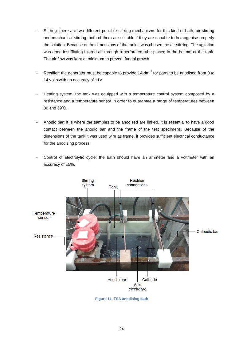
24
- Stirring: there are two different possible stirring mechanisms for this kind of bath, air stirring
and mechanical stirring, both of them are suitable if they are capable to homogenise properly
the solution. Because of the dimensions of the tank it was chosen the air stirring. The agitation
was done insufflating filtered air through a perforated tube placed in the bottom of the tank.
The air flow was kept at minimum to prevent fungal growth.
- Rectifier: the generator must be capable to provide 1A·dm-2
for parts to be anodised from 0 to
14 volts with an accuracy of ±1V.
- Heating system: the tank was equipped with a temperature control system composed by a
resistance and a temperature sensor in order to guarantee a range of temperatures between
36 and 39˚C.
- Anodic bar: it is where the samples to be anodised are linked. It is essential to have a good
contact between the anodic bar and the frame of the test specimens. Because of the
dimensions of the tank it was used wire as frame, it provides sufficient electrical conductance
for the anodising process.
- Control of electrolytic cycle: the bath should have an ammeter and a voltmeter with an
accuracy of ±5%.
Figure 11. TSA anodising bath
25
The anodising tank used for the tests was the small dimensions, but in the production line because of
the dimensions of the parts to be anodised it must be bigger. For this reason, it is necessary that the
tank has an extractor system to remove the vapour emitted during the anodising process.
In this kind of bath could be fungus growth because the electrolyte is less noxious and it facilitates
their proliferation. In consequence, baths with a long service life have to be equipped with an
antifungal system. It can be consisted of filtering elements of active carbon or ultraviolet lamps. As it
can be seen in Figure 11, the bath used had not any of these systems due to it was just a provisional
one and its service life was short.
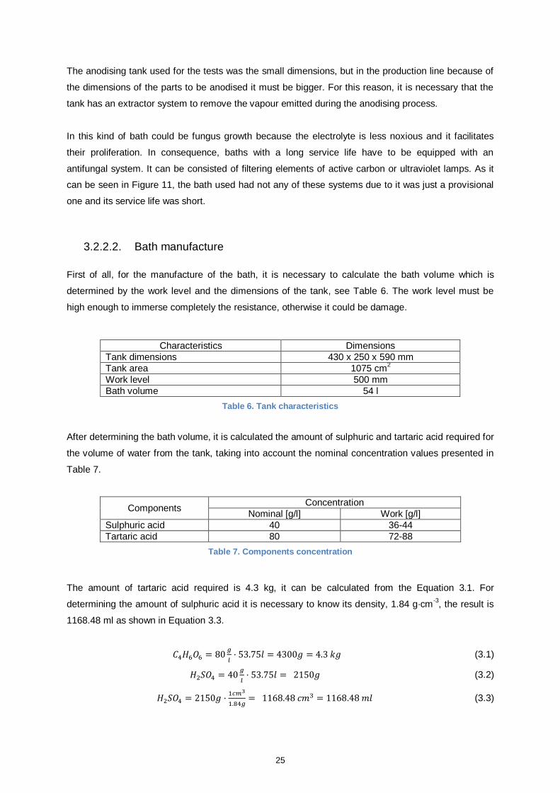
3.2.2.2. Bath manufacture
First of all, for the manufacture of the bath, it is necessary to calculate the bath volume which is
determined by the work level and the dimensions of the tank, see Table 6. The work level must be
high enough to immerse completely the resistance, otherwise it could be damage.
Characteristics Dimensions
Tank dimensions 430 x 250 x 590 mm
Tank area 1075 cm2
Work level 500 mm
Bath volume 54 l
Table 6. Tank characteristics
After determining the bath volume, it is calculated the amount of sulphuric and tartaric acid required for
the volume of water from the tank, taking into account the nominal concentration values presented in
Table 7.
Components Concentration
Nominal [g/l] Work [g/l]
Sulphuric acid 40 36-44
Tartaric acid 80 72-88
Table 7. Components concentration
The amount of tartaric acid required is 4.3 kg, it can be calculated from the Equation 3.1. For
determining the amount of sulphuric acid it is necessary to know its density, 1.84 g·cm-3, the result is
1168.48 ml as shown in Equation 3.3.
(3.1)
(3.2)
(3.3)
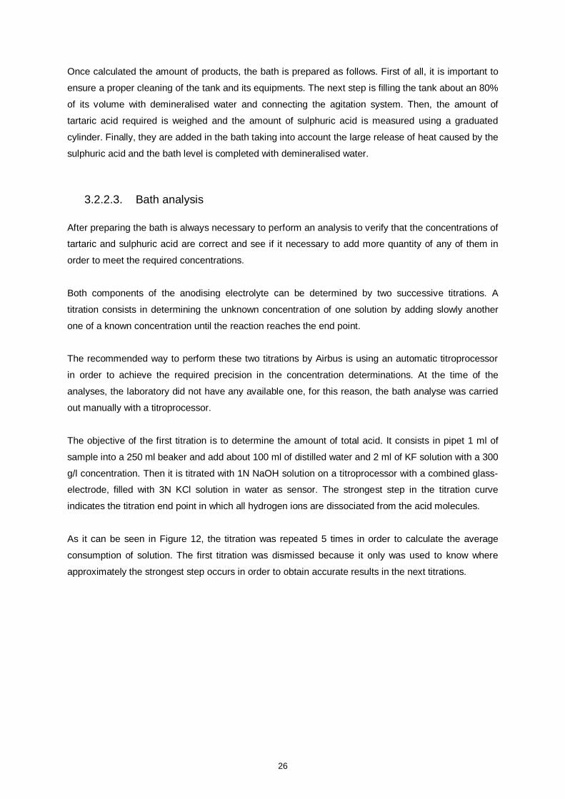
26
Once calculated the amount of products, the bath is prepared as follows. First of all, it is important to
ensure a proper cleaning of the tank and its equipments. The next step is filling the tank about an 80%
of its volume with demineralised water and connecting the agitation system. Then, the amount of
tartaric acid required is weighed and the amount of sulphuric acid is measured using a graduated
cylinder. Finally, they are added in the bath taking into account the large release of heat caused by the
sulphuric acid and the bath level is completed with demineralised water.
3.2.2.3. Bath analysis
After preparing the bath is always necessary to perform an analysis to verify that the concentrations of
tartaric and sulphuric acid are correct and see if it necessary to add more quantity of any of them in
order to meet the required concentrations.
Both components of the anodising electrolyte can be determined by two successive titrations. A
titration consists in determining the unknown concentration of one solution by adding slowly another
one of a known concentration until the reaction reaches the end point.
The recommended way to perform these two titrations by Airbus is using an automatic titroprocessor
in order to achieve the required precision in the concentration determinations. At the time of the
analyses, the laboratory did not have any available one, for this reason, the bath analyse was carried
out manually with a titroprocessor.
The objective of the first titration is to determine the amount of total acid. It consists in pipet 1 ml of
sample into a 250 ml beaker and add about 100 ml of distilled water and 2 ml of KF solution with a 300
g/l concentration. Then it is titrated with 1N NaOH solution on a titroprocessor with a combined glass-
electrode, filled with 3N KCl solution in water as sensor. The strongest step in the titration curve
indicates the titration end point in which all hydrogen ions are dissociated from the acid molecules.
As it can be seen in Figure 12, the titration was repeated 5 times in order to calculate the average
consumption of solution. The first titration was dismissed because it only was used to know where
approximately the strongest step occurs in order to obtain accurate results in the next titrations.
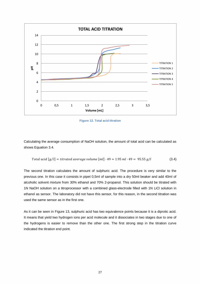
27
Figure 12. Total acid titration
Calculating the average consumption of NaOH solution, the amount of total acid can be calculated as
shows Equation 3.4.
(3.4)
The second titration calculates the amount of sulphuric acid. The procedure is very similar to the
previous one. In this case it consists in pipet 0,5ml of sample into a dry 50ml beaker and add 40ml of
alcoholic solvent mixture from 30% ethanol and 70% 2-propanol. This solution should be titrated with
1N NaOH solution on a titroprocessor with a combined glass-electrode filled with 1N LiCl solution in
ethanol as sensor. The laboratory did not have this sensor, for this reason, in the second titration was
used the same sensor as in the first one.
As it can be seen in Figure 13, sulphuric acid has two equivalence points because it is a diprotic acid.
It means that yield two hydrogen ions per acid molecule and it dissociates in two stages due to one of
the hydrogens is easier to remove than the other one. The first strong step in the titration curve
indicated the titration end point.
0
2
4
6
8
10
12
14
0 0,5 1 1,5 2 2,5 3 3,5
pH
Volume [mL]
TOTAL ACID TITRATION
TITRATION 1
TITRATION 2
TITRATION 3
TITRATION 4
TITRATION 5
28
Figure 13. Sulphuric acid titration
Calculating the average consumption of NaOH solution, the amount of sulphuric acid can be
calculated as shown in Equation 3.5.
(3.5)
If the determined value of sulphuric acid is subtracted from the total acid, the amount of tartaric acid
can be calculated as follows.
(3.6)
Although the procedure followed is correct, the results obtained are not very accurate because the
equipment used is not the suitable one. With the adequate tools, in a range from 20 to 60g·l-1
sulphuric
acid can be titrated directly with an accuracy of 5% and the tartaric acid can be calculated in a range
from 40 to 120 g·l-1
with an accuracy of 7% or better.
If the bath has a long service life, the analysis has to be done periodically in order to maintain the
required concentrations.
0
2
4
6
8
10
12
14
16
0 0,2 0,4 0,6 0,8 1 1,2
pH
Volume [ml]
SULPHURIC ACID TITRATION
TITRATION 1
TITRATION 2
TITRATION 3
TITRATION 4
29
3.2.2.4. Anodising process
Once the bath is manufactured and analysed, it is operative and ready for the anodising. After the pre-
treatments, the tests specimens were immersed completely in the anodising tank ensuring a good
connection for the current flow.
The electrolytic cycle should begin no later than 15 seconds after the immersion. As it can be seen in
Figure 14, it consists in an initial potential ramp from 0 to 14V for 5 minutes whose objective is to avoid
any current peak, then the voltage is maintained constant for 20 minutes and finally there is a final
potential ramp from 14 to 0V for thirty seconds. The current densities obtained are between 0.6 and
1A·dm-2
. There should not be current interruptions during the cycle. Once it is finished the tests
specimens should be removed from the bath as soon as possible, not later than 3 minutes after the
cycle’s finish.
Figure 14. TSA electrolytic cycle
The rinsing process after the TSA anodising is essential because without current the electrolyte could
attack the anodic film. All the samples were rinsed first with tap water and after with demineralised
water for minimum 6 minutes. After this last step, they were ready for the post-treatment which are
explained in the next sections.
Vo
ltag
e [V
]
Time [min]
ELECTROLYTIC CYCLE
5±0.5 20±1 0.5-1
14±1
30
3.2.3. Test specimen post-treatments
It is essential to have a good compatibility between the anodic film and the post-treatments. In this
thesis, it is studied the performance of some current ones: sealing with hot water; sealing with a
Chemical Conversion Coating (CCC), Bonderite® M-CR 1200S Aero; sealing with a Chromium VI
post-treatment, potassium dichromate; and a scheme of paint, primer and topcoat, in use by Airbus. In
the next sections there is a description and the main characteristics of each one.
3.2.3.1. Sealing with hot demineralised water
Sealing with hot demineralised water is used to close the pores after the anodising process. With this
bath the aluminium oxide, alumina, gets hydrated becoming mono-hydrated alumina which increases
in volume and closes the pores. It consists in immersing the tests specimens in demineralised hot
water between 40 to 60 minutes at a temperature above or equal to 95˚C.
All the samples were immersed in the tank for 40 minutes. The tank has a temperature control system
that keeps it at 97±2˚C. The pH has to be analysed and maintained between 5.5 and 6.5, if it is below
it should be corrected adding sodium hydroxide and if it is over then it should be corrected with
sulphuric acid.
After the immersion the test specimens were rinsed and finally they were dried first with compressed
air and then in oven at 60˚C for 20 minutes.
3.2.3.2. Sealing with Bonderite® M-CR 1200S Aero
The Bonderite® M-CR 1200S AERO, known as Bonderite® 1200S, is a Chemical Conversion Coating
(CCC) manufactured by Henkel. As it can be seen in the Table 8, it is based on hexavalent chromium.
It has a high level of performance in terms of corrosion resistance, thermal and electrical properties.
Component Percentage [%]
Chromium VI oxide (CrO3) 30-60
Potassium tetrafluoroborate (KBF4) 10-30
Tripotassium hexacyanoferrate (K3Fe(CN)6) 10-30
Sodium fluoride (NaF) 5-10
Dipotassium hexafluorozirconate (K2ZrF6) 5-10
Table 8. Bonderite® 1200S composition
Its nominal concentration in the bath is 19 g·l-1
and its maintenance values are between 15 and 22 g·l-
1, it does not need to be replenished often because has a long term stability. The pH must be
controlled and maintained between 1.3 and 1.8, if it is below ammonium hydroxide should be added
and if it is over then it should be added nitric acid.
31
Its operating temperature is from 21 to 30˚C, for this reason the tank has a temperature control system
that keeps it at 27±2˚C. The bath is also equipped with an air agitation system for stirring the products.
In contrast to other baths the immersion time is really short, between 0.25 seconds and 3 minutes.
The samples that received this post-treatment were immersed 2 minutes.
After the Bonderite® 1200S application, the test specimens were rinsed for 6 minutes in tap and
demineralised water, and dried first with compressed air and then in oven at 60˚C for 20 minutes.
3.2.3.3. Sealing with potassium dichromate
Potassium dichromate is a hexavalent chromium compound which provides a high resistance to
corrosion and saline conditions. Its concentration in the bath must be between 29 and 31 mg·l-1
and
the pH must be kept between 6 and 7.
The tank is equipped with a temperature control system that keeps it between 97 and 99˚C and has
and air stirring system for the agitation of the bath. The immersion time of the test specimens in this
bath was 20 minutes.
After the potassium dichromate bath, the samples were rinsed for minimum 6 minutes for removing
completely the product. Finally they were dried, first with compressed air and then in oven at 60˚C for
20 minutes.
3.2.3.4. Paint
After the anodising and the drying, the test specimens should be painted within 24 hours and must not
be exposed to adverse conditions or excessive contamination. The time can be increased to 168
hours if an ensure storage is guaranteed away of any pollution. In any case, it is better to paint the
samples as soon as possible to prevent damage on the coating film. After the application of the paint,
they have to be cured at room temperature for 7 days and then they are ready for performing the
adhesion tests.
3.2.3.4.1. Primer
The primer, also called undercoat, is applied directly on the TSA film. The main functions of the
primers are to improve the adhesion of the topcoat paint to the substrate, give more durability to the
paint and protect the surface of corrosion.
The primer applied on the samples is an epoxy primer in use by Airbus, called 37035A. It has
excellent adhesion properties on anodised substrates, it is resistant to aircraft hydraulic fluids and
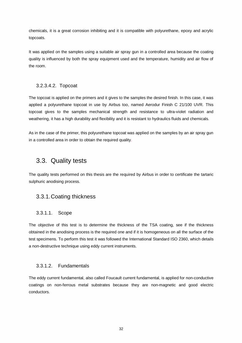
32
chemicals, it is a great corrosion inhibiting and it is compatible with polyurethane, epoxy and acrylic
topcoats.
It was applied on the samples using a suitable air spray gun in a controlled area because the coating
quality is influenced by both the spray equipment used and the temperature, humidity and air flow of
the room.
3.2.3.4.2. Topcoat
The topcoat is applied on the primers and it gives to the samples the desired finish. In this case, it was
applied a polyurethane topcoat in use by Airbus too, named Aerodur Finish C 21/100 UVR. This
topcoat gives to the samples mechanical strength and resistance to ultra-violet radiation and
weathering, it has a high durability and flexibility and it is resistant to hydraulics fluids and chemicals.
As in the case of the primer, this polyurethane topcoat was applied on the samples by an air spray gun
in a controlled area in order to obtain the required quality.
3.3. Quality tests
The quality tests performed on this thesis are the required by Airbus in order to certificate the tartaric
sulphuric anodising process.
3.3.1. Coating thickness
3.3.1.1. Scope
The objective of this test is to determine the thickness of the TSA coating, see if the thickness
obtained in the anodising process is the required one and if it is homogeneous on all the surface of the
test specimens. To perform this test it was followed the International Standard ISO 2360, which details
a non-destructive technique using eddy current instruments.
3.3.1.2. Fundamentals
The eddy current fundamental, also called Foucault current fundamental, is applied for non-conductive
coatings on non-ferrous metal substrates because they are non-magnetic and good electric
conductors.
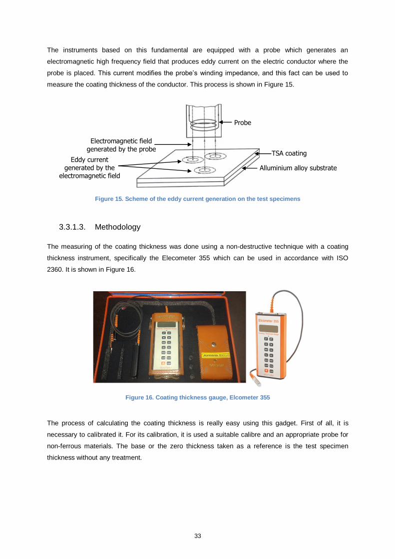
33
The instruments based on this fundamental are equipped with a probe which generates an
electromagnetic high frequency field that produces eddy current on the electric conductor where the
probe is placed. This current modifies the probe’s winding impedance, and this fact can be used to
measure the coating thickness of the conductor. This process is shown in Figure 15.
Figure 15. Scheme of the eddy current generation on the test specimens
3.3.1.3. Methodology
The measuring of the coating thickness was done using a non-destructive technique with a coating
thickness instrument, specifically the Elecometer 355 which can be used in accordance with ISO
2360. It is shown in Figure 16.
Figure 16. Coating thickness gauge, Elcometer 355
The process of calculating the coating thickness is really easy using this gadget. First of all, it is
necessary to calibrated it. For its calibration, it is used a suitable calibre and an appropriate probe for
non-ferrous materials. The base or the zero thickness taken as a reference is the test specimen
thickness without any treatment.
Probe
Alluminium alloy substrate
TSA coating
Electromagnetic field
generated by the probe
Eddy current generated by the
electromagnetic field
34
Once it was calibrated, 10 measurements on each specimen were done and the average value of
them was taken as the coating thickness. For each different sample the Elecometer 355 had to be
calibrated again because the base thickness changes. The results obtained are shown and discuss in
4.1.1.
3.3.1.4. Coating weight
3.3.1.5. Scope
The objective of this test is to determine the weight of the TSA coating film in order to check if the
weight obtained is the required one and see if the anodising process was successful. For performing
this test it was used the gravimetric method explained in the International Standard ISO 2106 for
determining the surface density of anodic oxidation coatings.
3.3.1.6. Methodology
For the determination of the coating weight it was used a destructive technique. It consists, first of all,
in cleaning the test specimens with distilled water. Then, they have to be dried for a minimum of 30
minutes at 93˚C and cooled to room temperature. Once they are cooled, they are weighed using a
balance sensitive to at least 10% of the anodic coating weight, in this test it was used the AG204
Mettler Toledo balance. After determining the initial weight, they have to be stripped by immersion
between 5 and 6 minutes at 100˚C in acid solution which composition can be seen in Table 9 .
Product Quantity
Phosphoric acid 85% 35ml
Chromic acid 20g
Demineralised water 1000ml
Table 9. Stripping solution
After the immersion, they must be washed with demineralised water, dried and weighed. The stripping
process has to be repeated until the weight of the samples remains constant which means that all the
coating is removed. Finally, using the total area of the test specimen, the sum of both areas’ faces,
and its initial and final weight the coating weight can be calculated as follows, Equation 3.7.
(3.7)
The results obtained with this process are presented and discuss in the 4.1.2.
35
3.3.2. Corrosion resistance
3.3.2.1. Scope
The objective of this test is to check the corrosion resistance of the treatments applied to the test
specimens, so it is used to characterize the effectiveness of their corrosion protection and to detect
defects and discontinuities. To perform this test it was followed the International Standard ISO 9227
that explains the corrosion test in artificial atmospheres using salt spray.
3.3.2.2. Fundamentals
In the laboratory a way to simulate the behaviour of the materials when they are exposed to a saline
atmosphere is using a salt spray chamber. It is based on spraying inside the chamber by means of
compressed air a corrosive agent, in this case sodium chloride dissolve in distilled water with a
concentration of 50g·l-1
at 35ºC.
The extremely aggressive environment produced inside the chamber lets to perform the test on an
accelerated way. There is no direct correlation between the corrosion inside the chamber and the one
in the real life for various reasons, but the most important ones can be summarized in three. The first
one is that inside the chamber the samples’ surface is always wet without any drying cycle as it
happens in real life. The second one is that the temperature inside the chamber is constant at 35ºC,
this increases and favours the transportation of the water, the oxygen and the chloride ion compared
with the external atmosphere. And the third one is that the NaCl has a concentration of 5% which is a
really high value, for example, the sea water has a concentration between 1.8% and 3%.
However, this test is widely used in industry for its simplicity and because it gives an accurate idea of
the corrosion resistance of the coatings checking the time taken for oxides to appear. If the coatings
are able to resist the aggressive conditions inside the chamber, they will be able to resist the
subsequent service environment.
3.3.2.3. Methodology
After the application of the inorganic coatings and a day of cure the test specimens are placed inside a
salt spray chamber. In this case, the salt spry chamber used was the Ascott S1000t which can be
seen in Figure 17.
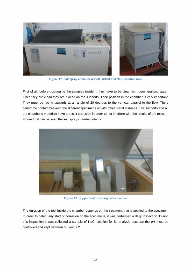
36
Figure 17. Salt spray chamber Ascott S1000t and NaCl solution tank
First of all, before positioning the samples inside it, they have to be clean with demineralised water.
Once they are clean they are placed on the supports. Their position in the chamber is very important.
They must be facing upwards at an angle of 20 degrees to the vertical, parallel to the flow. There
cannot be contact between the different specimens or with other metal surfaces. The supports and all
the chamber’s materials have to resist corrosion in order to not interfere with the results of the tests. In
Figure 18 it can be seen the salt spray chamber interior.
Figure 18. Supports of the spray salt chamber
The duration of the test inside the chamber depends on the treatment that is applied to the specimen.
In order to detect any start of corrosion on the specimens, it was performed a daily inspection. During
this inspection it was collected a sample of NaCl solution for its analysis because the pH must be
controlled and kept between 6.5 and 7.2.
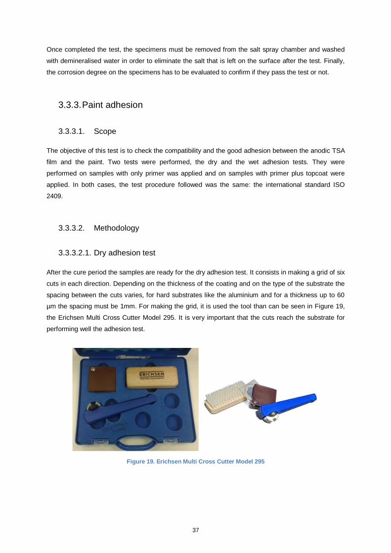
37
Once completed the test, the specimens must be removed from the salt spray chamber and washed
with demineralised water in order to eliminate the salt that is left on the surface after the test. Finally,
the corrosion degree on the specimens has to be evaluated to confirm if they pass the test or not.
3.3.3. Paint adhesion
3.3.3.1. Scope
The objective of this test is to check the compatibility and the good adhesion between the anodic TSA
film and the paint. Two tests were performed, the dry and the wet adhesion tests. They were
performed on samples with only primer was applied and on samples with primer plus topcoat were
applied. In both cases, the test procedure followed was the same: the international standard ISO
2409.
3.3.3.2. Methodology
3.3.3.2.1. Dry adhesion test
After the cure period the samples are ready for the dry adhesion test. It consists in making a grid of six
cuts in each direction. Depending on the thickness of the coating and on the type of the substrate the
spacing between the cuts varies, for hard substrates like the aluminium and for a thickness up to 60
µm the spacing must be 1mm. For making the grid, it is used the tool than can be seen in Figure 19,
the Erichsen Multi Cross Cutter Model 295. It is very important that the cuts reach the substrate for
performing well the adhesion test.
Figure 19. Erichsen Multi Cross Cutter Model 295
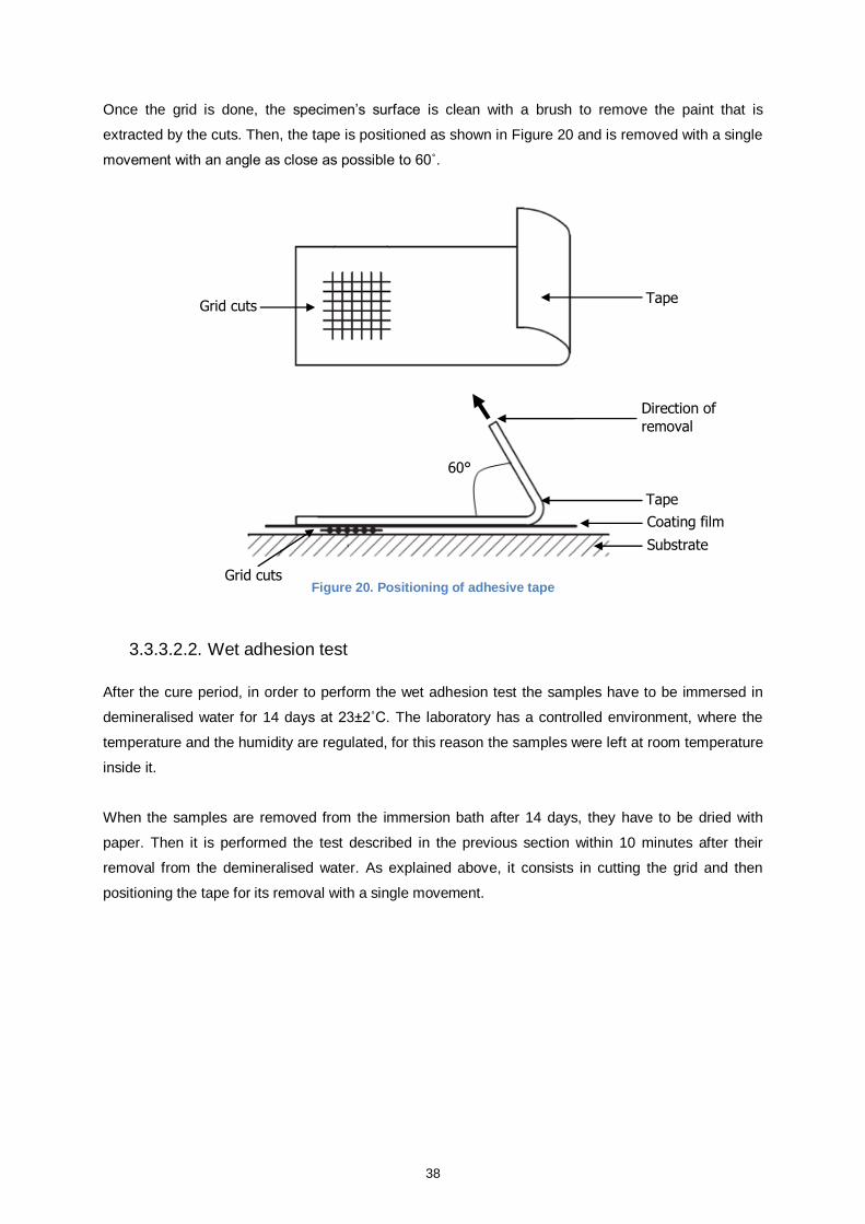
38
Once the grid is done, the specimen’s surface is clean with a brush to remove the paint that is
extracted by the cuts. Then, the tape is positioned as shown in Figure 20 and is removed with a single
movement with an angle as close as possible to 60˚.
Figure 20. Positioning of adhesive tape
3.3.3.2.2. Wet adhesion test
After the cure period, in order to perform the wet adhesion test the samples have to be immersed in
demineralised water for 14 days at 23±2˚C. The laboratory has a controlled environment, where the
temperature and the humidity are regulated, for this reason the samples were left at room temperature
inside it.
When the samples are removed from the immersion bath after 14 days, they have to be dried with
paper. Then it is performed the test described in the previous section within 10 minutes after their
removal from the demineralised water. As explained above, it consists in cutting the grid and then
positioning the tape for its removal with a single movement.
60°
Grid cuts
Tape
Coating film
Substrate
Direction of
removal
Tape Grid cuts
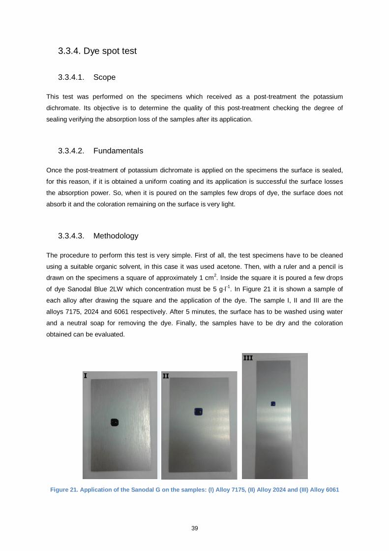
39
3.3.4. Dye spot test
3.3.4.1. Scope
This test was performed on the specimens which received as a post-treatment the potassium
dichromate. Its objective is to determine the quality of this post-treatment checking the degree of
sealing verifying the absorption loss of the samples after its application.
3.3.4.2. Fundamentals
Once the post-treatment of potassium dichromate is applied on the specimens the surface is sealed,
for this reason, if it is obtained a uniform coating and its application is successful the surface losses
the absorption power. So, when it is poured on the samples few drops of dye, the surface does not
absorb it and the coloration remaining on the surface is very light.
3.3.4.3. Methodology
The procedure to perform this test is very simple. First of all, the test specimens have to be cleaned
using a suitable organic solvent, in this case it was used acetone. Then, with a ruler and a pencil is
drawn on the specimens a square of approximately 1 cm2. Inside the square it is poured a few drops
of dye Sanodal Blue 2LW which concentration must be 5 g·l-1
. In Figure 21 it is shown a sample of
each alloy after drawing the square and the application of the dye. The sample I, II and III are the
alloys 7175, 2024 and 6061 respectively. After 5 minutes, the surface has to be washed using water
and a neutral soap for removing the dye. Finally, the samples have to be dry and the coloration
obtained can be evaluated.
Figure 21. Application of the Sanodal G on the samples: (I) Alloy 7175, (II) Alloy 2024 and (III) Alloy 6061
I II
III
40
3.3.5. Dye spot test with prior acid treatment
3.3.5.1. Scope
The objective of this test is to determine the quality of the anodic coatings checking their loss of
absorptive power after the sealing with hot water, in this case, it is verified the quality of the TSA
anodic coating. The test was performed following the International Standard ISO 2143.
3.3.5.2. Fundamentals
During the immersion inside the bath with hot water the pores that were open during the anodising are
closed, and the surface of the test specimens remains completely sealed. Therefore, if the anodising
and the sealing process have succeeded when it is applied on the surface a dye drop, the colour
remaining is very light because the surface repels it.
3.3.5.3. Methodology
First of all, the surface of the samples has to be cleaned and it is drawn on them with a ruler and a
pencil a square of approximately 1 cm2. Then it is necessary to prepare the acid solution composed of
25 ml·l-1
sulphuric acid and 10 g·l-1
potassium fluoride. Once the solution has been prepared, a spot is
applied inside the drawn square for 1 minute. After that, the surface has to be washed off and dried.
The next step after the application of the acid solution is to apply inside the square a drop of dye for
one minute, in this case it was applied 5 g·l-1
Sanodal Blue 2LW. Finally, the dye spot is washed off
with a mild abrasive soap and the coloration remaining on the specimen can be evaluated.
41
4. Results
4.1. Quality of the TSA anodic film
In this section the quality of the TSA anodic film is analysed based on the results got from the quality
tests explained in the previous sections.
The tests were performed on three different alloys: AA2024, AA7175 and AA6061. The preparation
procedure followed was the same for each one. They were immersed in the pre-degreasing, the
degreasing, the acid etching and the anodising bath. As the objective of this section is to study the
TSA coating quality, after these baths, the test specimens did not receive any post-treatment. Only for
the performance of the corrosion and dye spot tests the samples were immersed in the sealing tank of
hot demineralised water in order to close the pores of the TSA film.
With the performance of these tests three different parameters are compared and studied. First of all,
if there is a significant difference between the coating films obtained on the three different alloys, or
otherwise, if the results obtained are similar regardless its composition and its thermal treatment.
Also it is analysed if the etching bath has influence on the final results. It is verified if the new etching
bath without chromium compromises the effectiveness of the anodising process and it is confirmed if
the same results are achieved with both of them.
And the last analysis done is the comparison between the results obtained with the TSA anodising and
those obtained with the CAA anodising, to see if the first process is really a good substitute for the
second one.
In order to compare the efficiency of the Bonderite® Smutgo NCB, Bath 2, with the current etching
bath with chromium, Bath 1, the tests were performed for each alloy on two samples: one was
immersed in the first bath and the other in the second one.
All the information and values related with the CAA anodising tests were provided by the chemical
laboratory at OGMA. They have to perform monthly tests in order to ensure the quality of their surface
treatments. The results presented in the next sections correspond to the quality control tests of
February. However, the comparison between the CAA and the TSA processes is only performed for
the AA2024 and AA7175. This is because they are the only representative alloys of its production right
now, so, they do not need to perform tests on the AA6061.
42
4.1.1. TSA coating thickness
The TSA coating thickness was determined using the Elecometer 355 and following the procedure
explained in section 3.3.1. In Table 10 there are the results obtained, ten measurements of thickness
were made on different parts of the test specimens and the average value of them was taken as the
TSA coating thickness of the sample.
Test specimen Thickness [µm]
Standard deviation
[µm]
Average thickness
[µm] Material
Acid etching
AA2024 Bath 1 4.3 4.1 3.1 5.4 4.1 4.4 5.2 2.9 3.4 3.4 0.84 4.0
AA2024 Bath 2 2.9 3.5 3.6 3.8 3.3 3.1 3.7 2.9 2.8 3.4 0.36 3.3
AA7175 Bath 1 3.5 3.1 3.2 3.2 3.9 3.1 2.3 2.9 3.7 3.5 0.45 3.2
AA7175 Bath 2 5.1 4.5 4.4 3.9 3.8 3.9 4.1 4.2 3.7 4.3 0.41 4.2
AA6061 Bath 1 3.5 3.8 3.6 4.1 3.2 3.1 3.9 3.8 3.7 3.8 0.31 3.7
AA6061 Bath 2 2.8 2.1 3.5 3.3 4.4 2.9 2.7 4.4 3.1 2.4 0.77 3.2
Table 10. TSA coating thickness
There are different factors that could have affected the thickness measurements presented above and
they have to be taken into account in the analysis of the results. The first one is the edge effects. At
the edge of the samples the magnetic field is obstructed unless the instrument is correctly regulated,
for this reason it has avoided performing measurements there. The curvature and the roughness of
the surface can affect the measurements, too. In this case the curvature is not a problem because the
samples do not have it, but the roughness can produce both random and systematic errors. For
reducing the first error, it is necessary to make multiple measurements, in this case ten are considered
enough, and for avoiding the second one the calibration has been done on a base metal with an
equivalent roughness of the sample to be measured. The position of the probe it is also fundamental.
It must be placed tilt and directly on the sample, if not the gap between the sample and the probe can
introduce an extra thickness. The pressure made on the probe during the measurements and the
calibration must be constant, if not it can produce errors too. The temperature can affect the
characteristics of the probe, for this reason, it is important that the calibration and the measurements
take place in the same conditions. And finally, an external electromagnetic field can influence in the
measurements, so they have to be made far away of interfering fields. All the measurements shown in
Table 10 were made taking into account all the factors mentioned above.
Comparing the ten measurements made on each test specimen it can be seen that they are similar
along the entire surface. This means that the TSA film is homogeneous and there are not areas
without anodised.
The coating thicknesses obtained in each alloy are not only homogeneous but also satisfactory. The
thickness must be between 2 and 7 µm and they are around 3 and 4 µm. Also it can be seen that they
are similar, so, the TSA thickness film produced during the anodising process is not influenced by the
composition or the heat treatment of any alloy tested.
43
Analysing the thicknesses obtained in the same alloy but using a different etching bath, it cannot find
any significant differences in the results either. In the case of the AA2024 and AA6061 alloys, using
the Bonderite® Smutgo NCB the average thickness obtained is slightly smaller than using the first
bath, but their variation is not significant.
In the next tables, Table 11 and Table 12, there are the thicknesses obtained with the CAA process
provided by the chemical laboratory at OGMA. In Table 11 there are the coatings thicknesses of 4
different test specimens of the alloy AA7175 and in Table 12 there are the coating thickness of 4
different samples of the alloy AA2024.
Material Test specimens thickness [µm]
AA7175 2.8 2.9 5.4 4.2
Table 11. CAA coating thickness of the alloy 7175
Material Test specimens thickness [µm]
AA2024 3.7 3.9 3.9 4.5
Table 12. CAA coating thickness of the alloy 2024
The CAA coating thickness of the alloy AA7175 vary between 2.8 and 5.4 µm. If these values are
compared with the TSA anodising results it can be seen that they are similar, specially they are 3.2
and 4.2 µm.
In the case of the alloy AA2024, the variation of the CAA coating thicknesses is smaller. They are
between 3.7 and 4.5 µm. Comparing them with the TSA results it can be checked that they are almost
identical, since the TSA coating thickness obtained are 4.0 and 3.3 µm.
So, in terms of coating thickness it can be confirmed that the results obtained with the TSA anodising
are equivalent to those obtained with the CAA anodising.
4.1.2. TSA coating weight
The coating weight of each sample was calculated following the procedure explained in the section
3.3.1.4. As it can be seen in the Table 13, two different iterations were sufficient to remove all the
anodic coating film from the samples. It was considered that the weight remained constant when only
the last or the two last decimals varied between iterations. The results obtained are shown in the
Table 13.
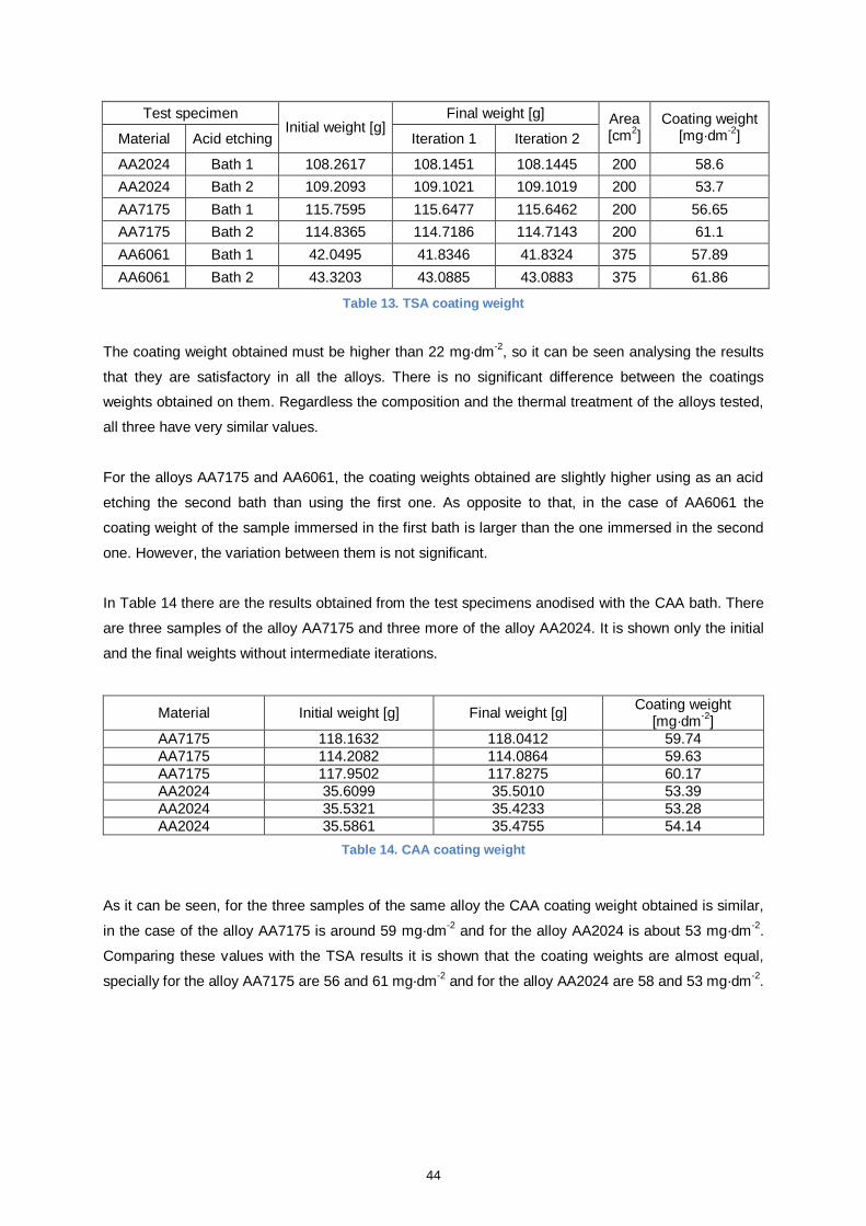
44
Test specimen Initial weight [g]
Final weight [g] Area [cm
2]
Coating weight [mg·dm
-2] Material Acid etching Iteration 1 Iteration 2
AA2024 Bath 1 108.2617 108.1451 108.1445 200 58.6
AA2024 Bath 2 109.2093 109.1021 109.1019 200 53.7
AA7175 Bath 1 115.7595 115.6477 115.6462 200 56.65
AA7175 Bath 2 114.8365 114.7186 114.7143 200 61.1
AA6061 Bath 1 42.0495 41.8346 41.8324 375 57.89
AA6061 Bath 2 43.3203 43.0885 43.0883 375 61.86
Table 13. TSA coating weight
The coating weight obtained must be higher than 22 mg·dm
-2, so it can be seen analysing the results
that they are satisfactory in all the alloys. There is no significant difference between the coatings
weights obtained on them. Regardless the composition and the thermal treatment of the alloys tested,
all three have very similar values.
For the alloys AA7175 and AA6061, the coating weights obtained are slightly higher using as an acid
etching the second bath than using the first one. As opposite to that, in the case of AA6061 the
coating weight of the sample immersed in the first bath is larger than the one immersed in the second
one. However, the variation between them is not significant.
In Table 14 there are the results obtained from the test specimens anodised with the CAA bath. There
are three samples of the alloy AA7175 and three more of the alloy AA2024. It is shown only the initial
and the final weights without intermediate iterations.
Material Initial weight [g] Final weight [g] Coating weight
[mg·dm-2
]
AA7175 118.1632 118.0412 59.74
AA7175 114.2082 114.0864 59.63
AA7175 117.9502 117.8275 60.17
AA2024 35.6099 35.5010 53.39
AA2024 35.5321 35.4233 53.28
AA2024 35.5861 35.4755 54.14
Table 14. CAA coating weight
As it can be seen, for the three samples of the same alloy the CAA coating weight obtained is similar,
in the case of the alloy AA7175 is around 59 mg·dm-2
and for the alloy AA2024 is about 53 mg·dm-2
.
Comparing these values with the TSA results it is shown that the coating weights are almost equal,
specially for the alloy AA7175 are 56 and 61 mg·dm-2
and for the alloy AA2024 are 58 and 53 mg·dm-2.
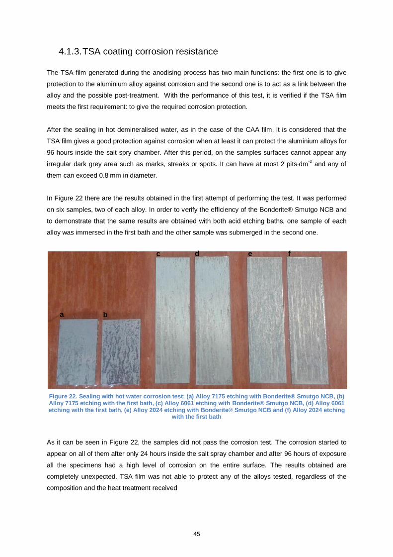
45
4.1.3. TSA coating corrosion resistance
The TSA film generated during the anodising process has two main functions: the first one is to give
protection to the aluminium alloy against corrosion and the second one is to act as a link between the
alloy and the possible post-treatment. With the performance of this test, it is verified if the TSA film
meets the first requirement: to give the required corrosion protection.
After the sealing in hot demineralised water, as in the case of the CAA film, it is considered that the
TSA film gives a good protection against corrosion when at least it can protect the aluminium alloys for
96 hours inside the salt spry chamber. After this period, on the samples surfaces cannot appear any
irregular dark grey area such as marks, streaks or spots. It can have at most 2 pits·dm-2
and any of
them can exceed 0.8 mm in diameter.
In Figure 22 there are the results obtained in the first attempt of performing the test. It was performed
on six samples, two of each alloy. In order to verify the efficiency of the Bonderite® Smutgo NCB and
to demonstrate that the same results are obtained with both acid etching baths, one sample of each
alloy was immersed in the first bath and the other sample was submerged in the second one.
Figure 22. Sealing with hot water corrosion test: (a) Alloy 7175 etching with Bonderite® Smutgo NCB, (b) Alloy 7175 etching with the first bath, (c) Alloy 6061 etching with Bonderite® Smutgo NCB, (d) Alloy 6061 etching with the first bath, (e) Alloy 2024 etching with Bonderite® Smutgo NCB and (f) Alloy 2024 etching
with the first bath
As it can be seen in Figure 22, the samples did not pass the corrosion test. The corrosion started to
appear on all of them after only 24 hours inside the salt spray chamber and after 96 hours of exposure
all the specimens had a high level of corrosion on the entire surface. The results obtained are
completely unexpected. TSA film was not able to protect any of the alloys tested, regardless of the
composition and the heat treatment received
a b
c d e f
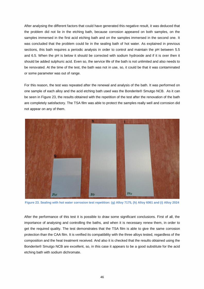
46
After analysing the different factors that could have generated this negative result, it was deduced that
the problem did not lie in the etching bath, because corrosion appeared on both samples, on the
samples immersed in the first acid etching bath and on the samples immersed in the second one. It
was concluded that the problem could lie in the sealing bath of hot water. As explained in previous
sections, this bath requires a periodic analysis in order to control and maintain the pH between 5.5
and 6.5. When the pH is below it should be corrected with sodium hydroxide and if it is over then it
should be added sulphuric acid. Even so, the service life of the bath is not unlimited and also needs to
be renovated. At the time of the test, the bath was not in use, so, it could be that it was contaminated
or some parameter was out of range.
For this reason, the test was repeated after the renewal and analysis of the bath. It was performed on
one sample of each alloy and the acid etching bath used was the Bonderite® Smutgo NCB. As it can
be seen in Figure 23, the results obtained with the repetition of the test after the renovation of the bath
are completely satisfactory. The TSA film was able to protect the samples really well and corrosion did
not appear on any of them.
Figure 23. Sealing with hot water corrosion test repetition: (g) Alloy 7175, (h) Alloy 6061 and (i) Alloy 2024
After the performance of this test it is possible to draw some significant conclusions. First of all, the
importance of analysing and controlling the baths, and when it is necessary renew them, in order to
get the required quality. The test demonstrates that the TSA film is able to give the same corrosion
protection than the CAA film. It is verified its compatibility with the three alloys tested, regardless of the
composition and the heat treatment received. And also it is checked that the results obtained using the
Bonderite® Smutgo NCB are excellent, so, in this case it appears to be a good substitute for the acid
etching bath with sodium dichromate.
g
h i
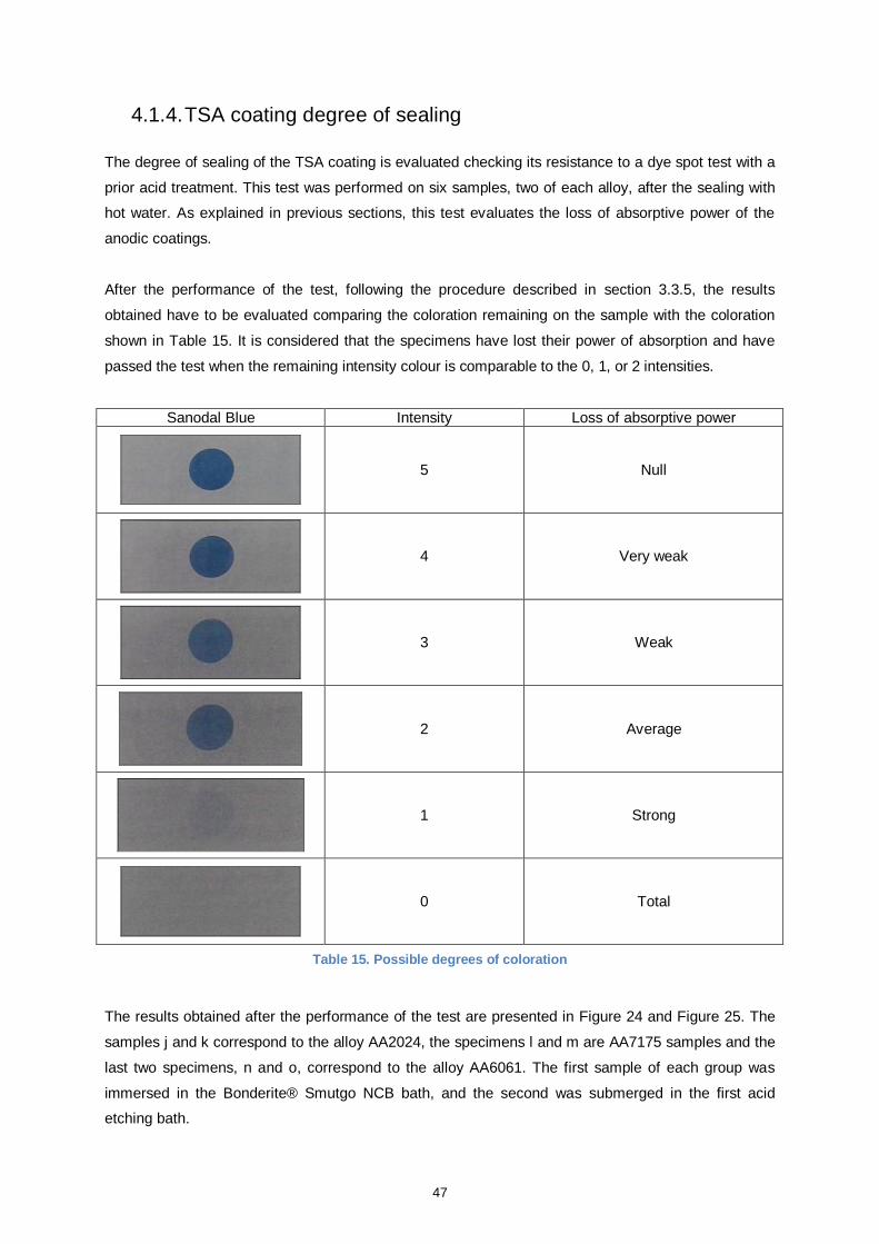
47
4.1.4. TSA coating degree of sealing
The degree of sealing of the TSA coating is evaluated checking its resistance to a dye spot test with a
prior acid treatment. This test was performed on six samples, two of each alloy, after the sealing with
hot water. As explained in previous sections, this test evaluates the loss of absorptive power of the
anodic coatings.
After the performance of the test, following the procedure described in section 3.3.5, the results
obtained have to be evaluated comparing the coloration remaining on the sample with the coloration
shown in Table 15. It is considered that the specimens have lost their power of absorption and have
passed the test when the remaining intensity colour is comparable to the 0, 1, or 2 intensities.
Sanodal Blue Intensity Loss of absorptive power
5 Null
4 Very weak
3 Weak
2 Average
1 Strong
0 Total
Table 15. Possible degrees of coloration
The results obtained after the performance of the test are presented in Figure 24 and Figure 25. The
samples j and k correspond to the alloy AA2024, the specimens l and m are AA7175 samples and the
last two specimens, n and o, correspond to the alloy AA6061. The first sample of each group was
immersed in the Bonderite® Smutgo NCB bath, and the second was submerged in the first acid
etching bath.
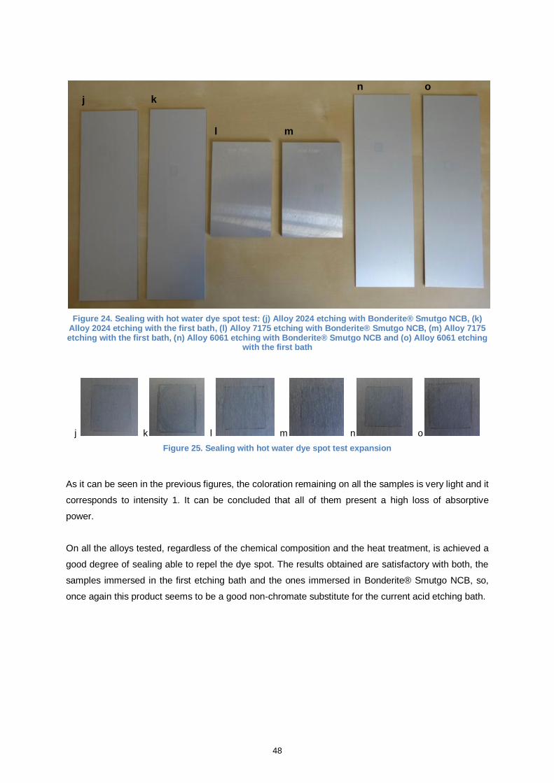
48
Figure 24. Sealing with hot water dye spot test: (j) Alloy 2024 etching with Bonderite® Smutgo NCB, (k) Alloy 2024 etching with the first bath, (l) Alloy 7175 etching with Bonderite® Smutgo NCB, (m) Alloy 7175 etching with the first bath, (n) Alloy 6061 etching with Bonderite® Smutgo NCB and (o) Alloy 6061 etching
with the first bath
j k l m n o
Figure 25. Sealing with hot water dye spot test expansion
As it can be seen in the previous figures, the coloration remaining on all the samples is very light and it
corresponds to intensity 1. It can be concluded that all of them present a high loss of absorptive
power.
On all the alloys tested, regardless of the chemical composition and the heat treatment, is achieved a
good degree of sealing able to repel the dye spot. The results obtained are satisfactory with both, the
samples immersed in the first etching bath and the ones immersed in Bonderite® Smutgo NCB, so,
once again this product seems to be a good non-chromate substitute for the current acid etching bath.
j k
l m
n o
49
4.2. Quality of the post-treatments
In this section it is studied and analysed the compatibility of the TSA coating film with the different
post-treatments. One of the TSA film main functions is to provide and facilitate a good adhesion
between the aluminium alloy and them, for this reason it is fundamental to check if exists a perfect link
between both and if they provide a good protection to the alloy.
Depending on the post-treatment it was performed different types of tests in order to check its quality.
For the potassium dichromate it was performed two tests: it was checked its corrosion resistance and
its loss of absorptive power. In the case of the test specimens with Bonderite® 1200S it was
performed only the corrosion resistance test. And for the painted samples it was analysed the dry and
wet adhesion achieved.
4.2.1. Post-treatments corrosion resistance
4.2.1.1. Sealing with potassium dichromate
The samples sealed with potassium dichromate were placed inside the saline chamber after one day
of cure. This treatment is considered to give a good corrosion resistance when after 336 hours of
exposure the samples show less than 2 pits·dm-2
and any of them exceed 0.8 mm in diameter. On the
test specimen surface cannot be any irregular dark grey areas such as spots, streaks or marks.
In order to perform the test the samples were placed inside the saline chamber with an inclination of
20 degrees from the vertical. Although the total duration of the test was 336 hours, it was carried out
daily inspections to detect the start of any appearance of corrosion during the test.
In the following two figures, Figure 26 and Figure 27, can be seen the samples after performing the
test. In the first one, there are the six samples immersed in the etching bath with chromium and in the
second one there are the samples which received the acid etching with Bonderite® Smutgo NCB.
The first two samples of each figure, group A and group D, correspond to the alloy AA2024. The
second groups, group B and E, are samples of the alloy AA7175. And the last two groups of each
figure, group C and F, correspond to the alloy AA6061.

50
Figure 26. Potassium dichromate corrosion test with etching bath 1: (A) Alloy 2024, (B) Alloy 7175 and (C) Alloy 6061
Figure 27. Potassium dichromate corrosion test with etching bath 2: (D) Alloy 2024, (E) Alloy 7175 and (F) Alloy 6061
As it can be seen the results obtained are completely satisfactory because after 336 hours of test
there is no evidence of corrosion on any of the test specimens. It can be concluded that the potassium
dichromate is completely compatible with the coating film produced in the TSA anodising bath in the
case of all the alloys tested and confirm that their combination provide the corrosion resistance
required.
Comparing the test specimens immersed in the two different acid etching baths, it can also be affirmed
that using the Bonderite® Smutgo NCB the results achieved in terms of corrosion resistance are
equivalent to those obtained with the etching bath with chromium.
A B
C
E
F
D
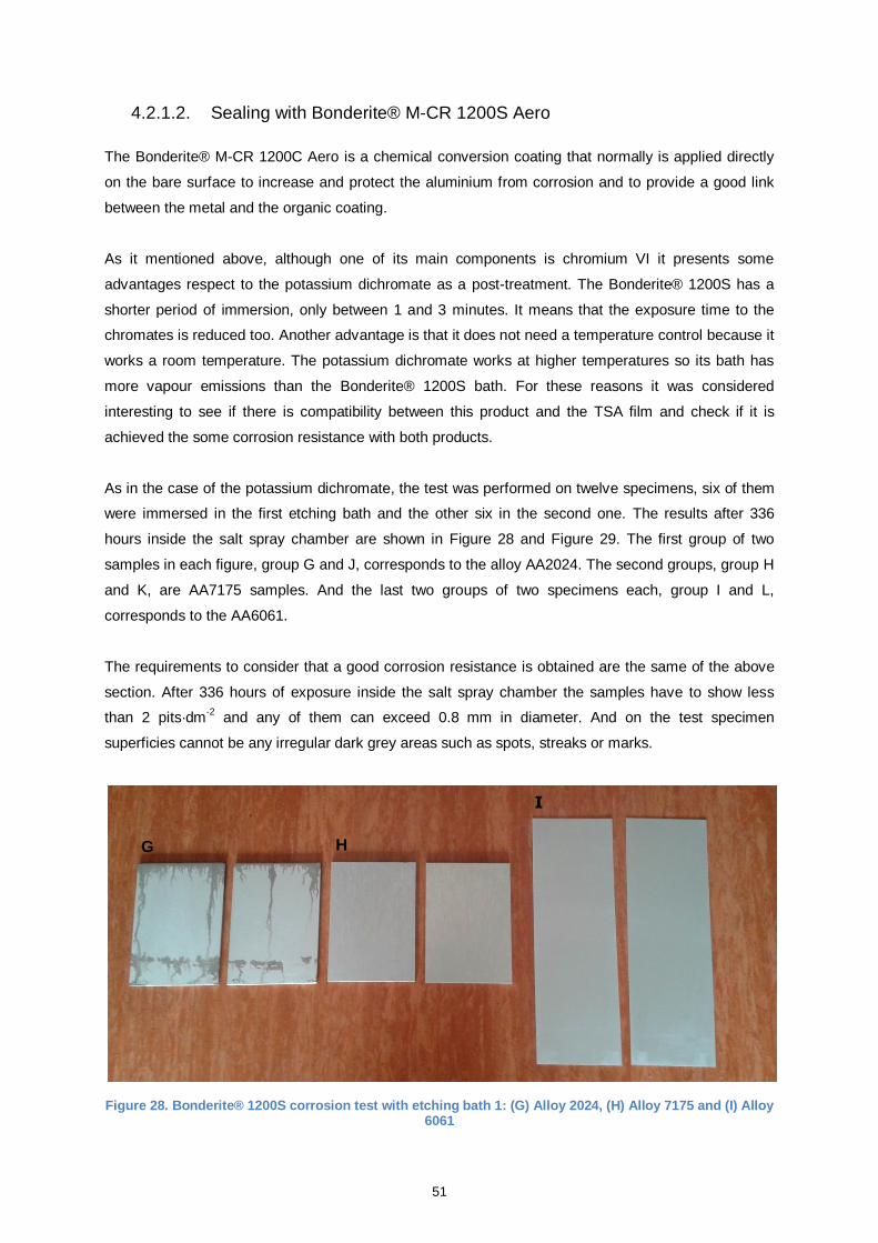
51
4.2.1.2. Sealing with Bonderite® M-CR 1200S Aero
The Bonderite® M-CR 1200C Aero is a chemical conversion coating that normally is applied directly
on the bare surface to increase and protect the aluminium from corrosion and to provide a good link
between the metal and the organic coating.
As it mentioned above, although one of its main components is chromium VI it presents some
advantages respect to the potassium dichromate as a post-treatment. The Bonderite® 1200S has a
shorter period of immersion, only between 1 and 3 minutes. It means that the exposure time to the
chromates is reduced too. Another advantage is that it does not need a temperature control because it
works a room temperature. The potassium dichromate works at higher temperatures so its bath has
more vapour emissions than the Bonderite® 1200S bath. For these reasons it was considered
interesting to see if there is compatibility between this product and the TSA film and check if it is
achieved the some corrosion resistance with both products.
As in the case of the potassium dichromate, the test was performed on twelve specimens, six of them
were immersed in the first etching bath and the other six in the second one. The results after 336
hours inside the salt spray chamber are shown in Figure 28 and Figure 29. The first group of two
samples in each figure, group G and J, corresponds to the alloy AA2024. The second groups, group H
and K, are AA7175 samples. And the last two groups of two specimens each, group I and L,
corresponds to the AA6061.
The requirements to consider that a good corrosion resistance is obtained are the same of the above
section. After 336 hours of exposure inside the salt spray chamber the samples have to show less
than 2 pits·dm-2
and any of them can exceed 0.8 mm in diameter. And on the test specimen
superficies cannot be any irregular dark grey areas such as spots, streaks or marks.
Figure 28. Bonderite® 1200S corrosion test with etching bath 1: (G) Alloy 2024, (H) Alloy 7175 and (I) Alloy 6061
H G
I
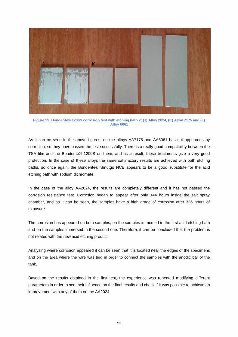
52
Figure 29. Bonderite® 1200S corrosion test with etching bath 2: (J) Alloy 2024, (K) Alloy 7175 and (L) Alloy 6061
As it can be seen in the above figures, on the alloys AA7175 and AA6061 has not appeared any
corrosion, so they have passed the test successfully. There is a really good compatibility between the
TSA film and the Bonderite® 1200S on them, and as a result, these treatments give a very good
protection. In the case of these alloys the same satisfactory results are achieved with both etching
baths, so once again, the Bonderite® Smutgo NCB appears to be a good substitute for the acid
etching bath with sodium dichromate.
In the case of the alloy AA2024, the results are completely different and it has not passed the
corrosion resistance test. Corrosion began to appear after only 144 hours inside the salt spray
chamber, and as it can be seen, the samples have a high grade of corrosion after 336 hours of
exposure.
The corrosion has appeared on both samples, on the samples immersed in the first acid etching bath
and on the samples immersed in the second one. Therefore, it can be concluded that the problem is
not related with the new acid etching product.
Analysing where corrosion appeared it can be seen that it is located near the edges of the specimens
and on the area where the wire was tied in order to connect the samples with the anodic bar of the
tank.
Based on the results obtained in the first test, the experience was repeated modifying different
parameters in order to see their influence on the final results and check if it was possible to achieve an
improvement with any of them on the AA2024.
J K
L
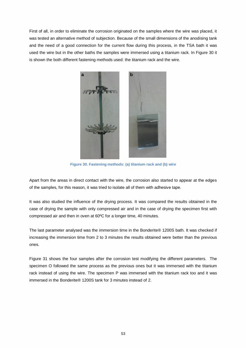
53
First of all, in order to eliminate the corrosion originated on the samples where the wire was placed, it
was tested an alternative method of subjection. Because of the small dimensions of the anodising tank
and the need of a good connection for the current flow during this process, in the TSA bath it was
used the wire but in the other baths the samples were immersed using a titanium rack. In Figure 30 it
is shown the both different fastening methods used: the titanium rack and the wire.
Figure 30. Fastening methods: (a) titanium rack and (b) wire
Apart from the areas in direct contact with the wire, the corrosion also started to appear at the edges
of the samples, for this reason, it was tried to isolate all of them with adhesive tape.
It was also studied the influence of the drying process. It was compared the results obtained in the
case of drying the sample with only compressed air and in the case of drying the specimen first with
compressed air and then in oven at 60ºC for a longer time, 40 minutes.
The last parameter analysed was the immersion time in the Bonderite® 1200S bath. It was checked if
increasing the immersion time from 2 to 3 minutes the results obtained were better than the previous
ones.
Figure 31 shows the four samples after the corrosion test modifying the different parameters. The
specimen O followed the same process as the previous ones but it was immersed with the titanium
rack instead of using the wire. The specimen P was immersed with the titanium rack too and it was
immersed in the Bonderite® 1200S tank for 3 minutes instead of 2.
a b
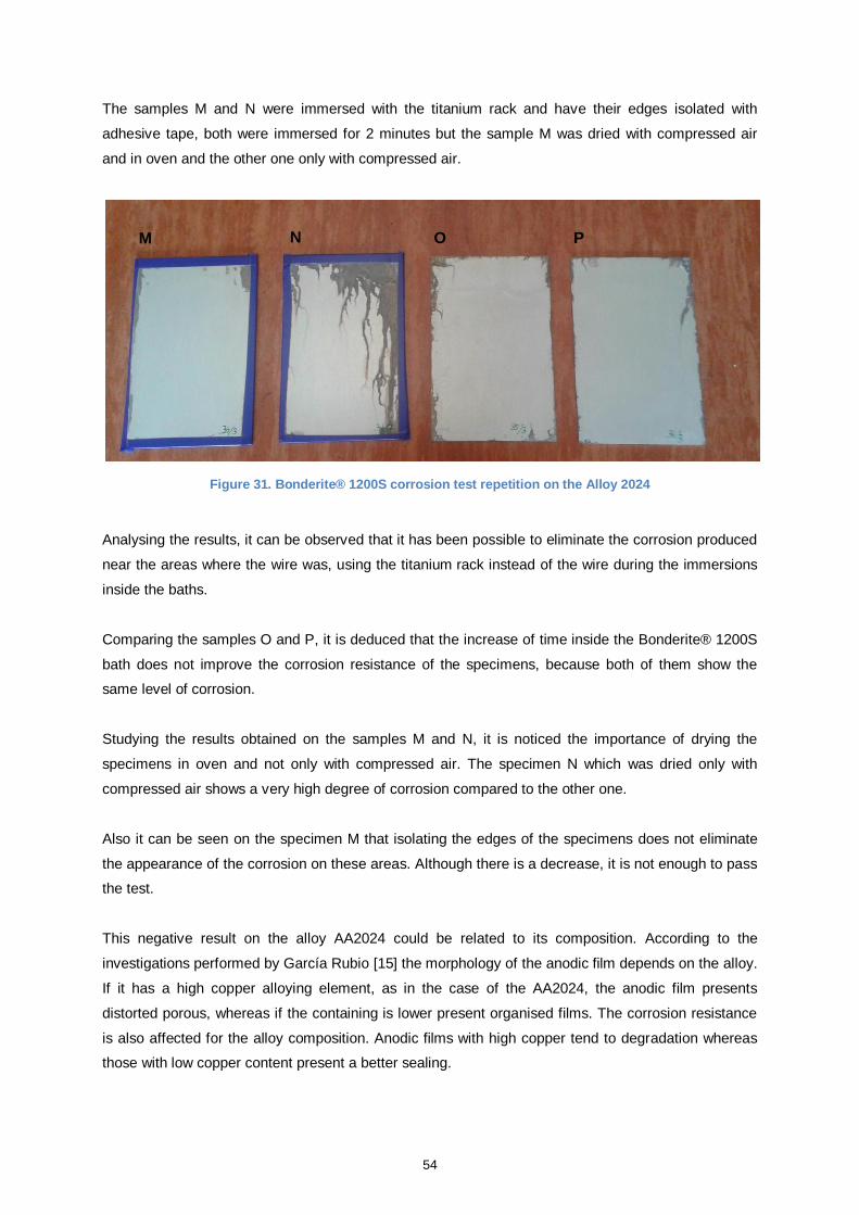
54
The samples M and N were immersed with the titanium rack and have their edges isolated with
adhesive tape, both were immersed for 2 minutes but the sample M was dried with compressed air
and in oven and the other one only with compressed air.
Figure 31. Bonderite® 1200S corrosion test repetition on the Alloy 2024
Analysing the results, it can be observed that it has been possible to eliminate the corrosion produced
near the areas where the wire was, using the titanium rack instead of the wire during the immersions
inside the baths.
Comparing the samples O and P, it is deduced that the increase of time inside the Bonderite® 1200S
bath does not improve the corrosion resistance of the specimens, because both of them show the
same level of corrosion.
Studying the results obtained on the samples M and N, it is noticed the importance of drying the
specimens in oven and not only with compressed air. The specimen N which was dried only with
compressed air shows a very high degree of corrosion compared to the other one.
Also it can be seen on the specimen M that isolating the edges of the specimens does not eliminate
the appearance of the corrosion on these areas. Although there is a decrease, it is not enough to pass
the test.
This negative result on the alloy AA2024 could be related to its composition. According to the
investigations performed by García Rubio [15] the morphology of the anodic film depends on the alloy.
If it has a high copper alloying element, as in the case of the AA2024, the anodic film presents
distorted porous, whereas if the containing is lower present organised films. The corrosion resistance
is also affected for the alloy composition. Anodic films with high copper tend to degradation whereas
those with low copper content present a better sealing.
M N O P
55
After the analysis performed it can be concluded that the Bonderite® 1200S as a post-treatment is
compatible with the TSA anodising in the case of the alloys AA7175 and AA6061. In the case of
AA2024, although it has been possible to reduce the initial corrosion, it has not been entirely
eliminated and has not passed the corrosion test.
4.2.2. Post-treatments dye spot resistance
4.2.2.1. Sealing with potassium dichromate
This test was performed on samples sealed with potassium dichromate. The objective of this test is to
check the sealing quality of this post-treatment on the TSA anodic film. In order to verify their affinity
and see if the samples are well sealed this test analyses the loss of absorptive power.
As in the case of sealing with hot water, the results obtained are evaluated comparing the coloration
remaining on the sample with the coloration shown in Table 15. The specimens have lost their power
of absorption and have passed the test when the remaining intensity colour is comparable to the 0, 1,
or 2 intensities.
In total the test was carried out on six test specimens, two of each alloy. One of them was immersed in
the Bonderite® Smutgo NCB bath for the acid etching process and the other one was immersed in the
first bath. So, it is possible to check and compare if there is a good sealing on the different alloys and
if the some results are achieved using both acid etching baths.
The results obtained are shown in Figure 32. The samples Q and R correspond to the alloy AA2024,
the specimens S and T are AA7175 samples and the last two specimens, U and V, correspond to the
alloy AA6061. The first sample of each group (Q, S and U) was immersed in the Bonderite® Smutgo
NCB bath. And the second one of each group (R, T and V) was immersed in the first acid etching
bath.
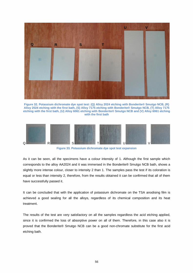
56
Figure 32. Potassium dichromate dye spot test: (Q) Alloy 2024 etching with Bonderite® Smutgo NCB, (R) Alloy 2024 etching with the first bath, (S) Alloy 7175 etching with Bonderite® Smutgo NCB, (T) Alloy 7175 etching with the first bath, (U) Alloy 6061 etching with Bonderite® Smutgo NCB and (V) Alloy 6061 etching
with the first bath
Q R S T U V
Figure 33. Potassium dichromate dye spot test expansion
As it can be seen, all the specimens have a colour intensity of 1. Although the first sample which
corresponds to the alloy AA2024 and it was immersed in the Bonderite® Smutgo NCB bath, shows a
slightly more intense colour, closer to intensity 2 than 1. The samples pass the test if its coloration is
equal or less than intensity 2, therefore, from the results obtained it can be confirmed that all of them
have successfully passed it.
It can be concluded that with the application of potassium dichromate on the TSA anodising film is
achieved a good sealing for all the alloys, regardless of its chemical composition and its heat
treatment.
The results of the test are very satisfactory on all the samples regardless the acid etching applied,
since it is confirmed the loss of absorptive power on all of them. Therefore, in this case also it is
proved that the Bonderite® Smutgo NCB can be a good non-chromate substitute for the first acid
etching bath.
Q R S T
U V
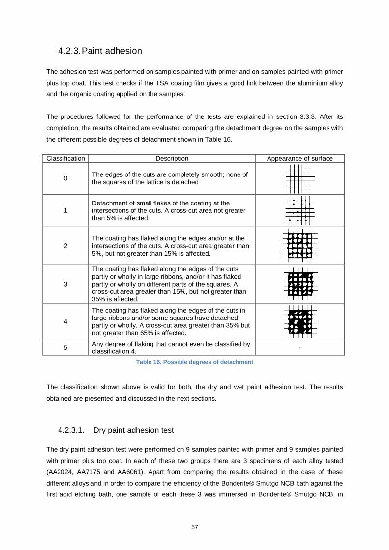
57
4.2.3. Paint adhesion
The adhesion test was performed on samples painted with primer and on samples painted with primer
plus top coat. This test checks if the TSA coating film gives a good link between the aluminium alloy
and the organic coating applied on the samples.
The procedures followed for the performance of the tests are explained in section 3.3.3. After its
completion, the results obtained are evaluated comparing the detachment degree on the samples with
the different possible degrees of detachment shown in Table 16.
Classification Description Appearance of surface
0 The edges of the cuts are completely smooth; none of the squares of the lattice is detached
1 Detachment of small flakes of the coating at the intersections of the cuts. A cross-cut area not greater than 5% is affected.
2 The coating has flaked along the edges and/or at the intersections of the cuts. A cross-cut area greater than 5%, but not greater than 15% is affected.
3
The coating has flaked along the edges of the cuts partly or wholly in large ribbons, and/or it has flaked partly or wholly on different parts of the squares. A cross-cut area greater than 15%, but not greater than 35% is affected.
4
The coating has flaked along the edges of the cuts in large ribbons and/or some squares have detached partly or wholly. A cross-cut area greater than 35% but not greater than 65% is affected.
5 Any degree of flaking that cannot even be classified by classification 4.
-
Table 16. Possible degrees of detachment
The classification shown above is valid for both, the dry and wet paint adhesion test. The results
obtained are presented and discussed in the next sections.
4.2.3.1. Dry paint adhesion test
The dry paint adhesion test were performed on 9 samples painted with primer and 9 samples painted
with primer plus top coat. In each of these two groups there are 3 specimens of each alloy tested
(AA2024, AA7175 and AA6061). Apart from comparing the results obtained in the case of these
different alloys and in order to compare the efficiency of the Bonderite® Smutgo NCB bath against the
first acid etching bath, one sample of each these 3 was immersed in Bonderite® Smutgo NCB, in
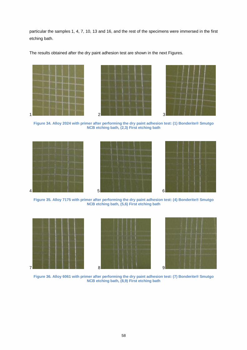
58
particular the samples 1, 4, 7, 10, 13 and 16, and the rest of the specimens were immersed in the first
etching bath.
The results obtained after the dry paint adhesion test are shown in the next Figures.
1 2 3
Figure 34. Alloy 2024 with primer after performing the dry paint adhesion test: (1) Bonderite® Smutgo NCB etching bath, (2,3) First etching bath
4 5 6
Figure 35. Alloy 7175 with primer after performing the dry paint adhesion test: (4) Bonderite® Smutgo NCB etching bath, (5,6) First etching bath
7 8 9
Figure 36. Alloy 6061 with primer after performing the dry paint adhesion test: (7) Bonderite® Smutgo NCB etching bath, (8,9) First etching bath
59
10 11 12
Figure 37. Alloy 2024 with primer plus top coat after performing the dry paint adhesion test: (10) Bonderite® Smutgo NCB etching bath, (11,12) First etching bath
13 14 15
Figure 38. Alloy 7175 with primer plus top coat after performing the dry paint adhesion test: (13) Bonderite® Smutgo NCB etching bath, (14,15) First etching bath
16 17 18
Figure 39. Alloy 6061 with primer plus top coat after performing the dry paint adhesion test: (16) Bonderite® Smutgo NCB etching bath, (17,18) First etching bath
Comparing the samples detachment degree after the performance of the test with the possible
detachment degrees shown in Table 16, it can be seen that it corresponds to classification 0 on the
samples painted with primer because none of the squares of the grid is removed.
In the case of the samples painted with primer plus top coat the same good results are achieved.
There are not detachments of paint along the cuts or in their intersection, so it corresponds to
classification 0, too.
.
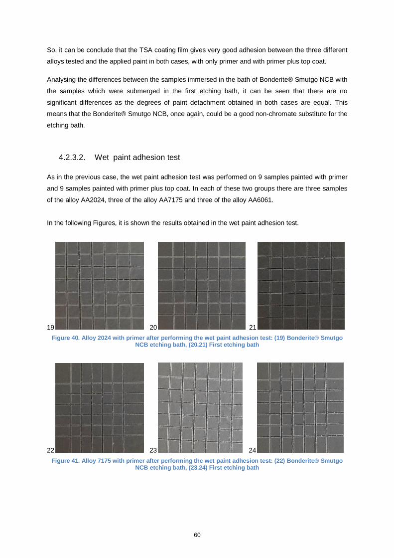
60
So, it can be conclude that the TSA coating film gives very good adhesion between the three different
alloys tested and the applied paint in both cases, with only primer and with primer plus top coat.
Analysing the differences between the samples immersed in the bath of Bonderite® Smutgo NCB with
the samples which were submerged in the first etching bath, it can be seen that there are no
significant differences as the degrees of paint detachment obtained in both cases are equal. This
means that the Bonderite® Smutgo NCB, once again, could be a good non-chromate substitute for the
etching bath.
4.2.3.2. Wet paint adhesion test
As in the previous case, the wet paint adhesion test was performed on 9 samples painted with primer
and 9 samples painted with primer plus top coat. In each of these two groups there are three samples
of the alloy AA2024, three of the alloy AA7175 and three of the alloy AA6061.
In the following Figures, it is shown the results obtained in the wet paint adhesion test.
19 20 21
Figure 40. Alloy 2024 with primer after performing the wet paint adhesion test: (19) Bonderite® Smutgo NCB etching bath, (20,21) First etching bath
22 23 24
Figure 41. Alloy 7175 with primer after performing the wet paint adhesion test: (22) Bonderite® Smutgo NCB etching bath, (23,24) First etching bath
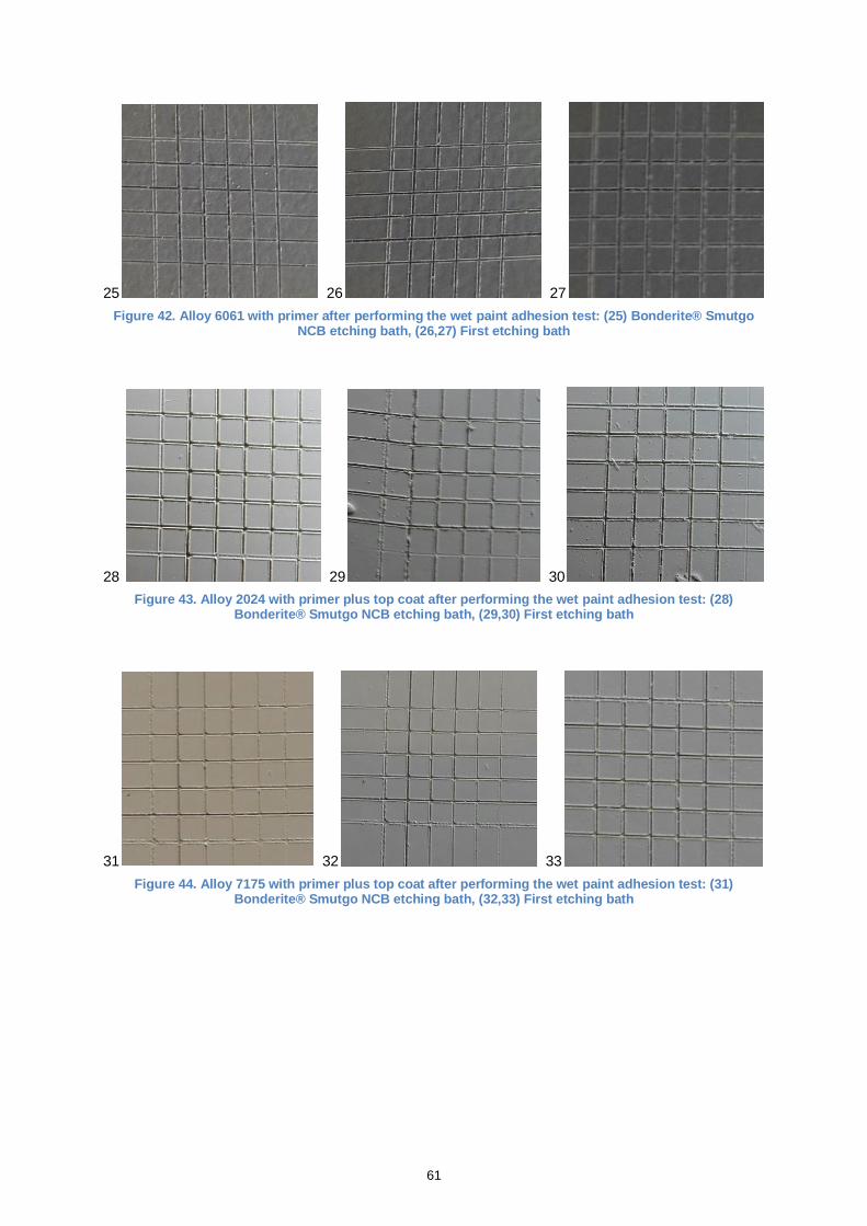
61
25 26 27
Figure 42. Alloy 6061 with primer after performing the wet paint adhesion test: (25) Bonderite® Smutgo NCB etching bath, (26,27) First etching bath
28 29 30
Figure 43. Alloy 2024 with primer plus top coat after performing the wet paint adhesion test: (28) Bonderite® Smutgo NCB etching bath, (29,30) First etching bath
31 32 33
Figure 44. Alloy 7175 with primer plus top coat after performing the wet paint adhesion test: (31) Bonderite® Smutgo NCB etching bath, (32,33) First etching bath
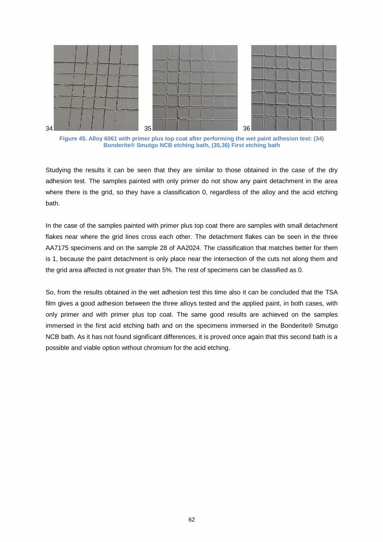
62
34 35 36
Figure 45. Alloy 6061 with primer plus top coat after performing the wet paint adhesion test: (34) Bonderite® Smutgo NCB etching bath, (35,36) First etching bath
Studying the results it can be seen that they are similar to those obtained in the case of the dry
adhesion test. The samples painted with only primer do not show any paint detachment in the area
where there is the grid, so they have a classification 0, regardless of the alloy and the acid etching
bath.
In the case of the samples painted with primer plus top coat there are samples with small detachment
flakes near where the grid lines cross each other. The detachment flakes can be seen in the three
AA7175 specimens and on the sample 28 of AA2024. The classification that matches better for them
is 1, because the paint detachment is only place near the intersection of the cuts not along them and
the grid area affected is not greater than 5%. The rest of specimens can be classified as 0.
So, from the results obtained in the wet adhesion test this time also it can be concluded that the TSA
film gives a good adhesion between the three alloys tested and the applied paint, in both cases, with
only primer and with primer plus top coat. The same good results are achieved on the samples
immersed in the first acid etching bath and on the specimens immersed in the Bonderite® Smutgo
NCB bath. As it has not found significant differences, it is proved once again that this second bath is a
possible and viable option without chromium for the acid etching.
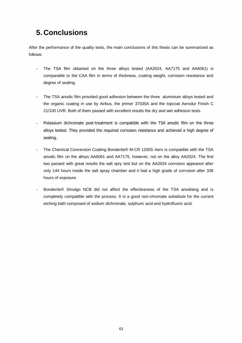
63
5. Conclusions
After the performance of the quality tests, the main conclusions of this thesis can be summarized as
follows:
- The TSA film obtained on the three alloys tested (AA2024, AA7175 and AA6061) is
comparable to the CAA film in terms of thickness, coating weight, corrosion resistance and
degree of sealing.
- The TSA anodic film provided good adhesion between the three aluminium alloys tested and
the organic coating in use by Airbus, the primer 37035A and the topcoat Aerodur Finish C
21/100 UVR. Both of them passed with excellent results the dry and wet adhesion tests.
- Potassium dichromate post-treatment is compatible with the TSA anodic film on the three
alloys tested. They provided the required corrosion resistance and achieved a high degree of
sealing.
- The Chemical Conversion Coating Bonderite® M-CR 1200S Aero is compatible with the TSA
anodic film on the alloys AA6061 and AA7175, however, not on the alloy AA2024. The first
two passed with great results the salt spry test but on the AA2024 corrosion appeared after
only 144 hours inside the salt spray chamber and it had a high grade of corrosion after 336
hours of exposure.
- Bonderite® Smutgo NCB did not affect the effectiveness of the TSA anodising and is
completely compatible with the process. It is a good non-chromate substitute for the current
etching bath composed of sodium dichromate, sulphuric acid and hydrofluoric acid.
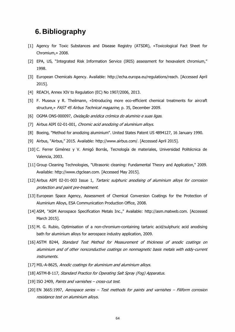
64
6. Bibliography
[1] Agency for Toxic Substances and Disease Registry (ATSDR), «Toxicological Fact Sheet for
Chromium,» 2008.
[2] EPA, US, “Integrated Risk Information Service (IRIS) assessment for hexavalent chromium,”
1998.
[3] European Chemicals Agency. Available: http://echa.europa.eu/regulations/reach. [Accessed April
2015].
[4] REACH, Annex XIV to Regulation (EC) No 1907/2006, 2013.
[5] F. Museux y R. Theilmann, «Introducing more eco-efficient chemical treatments for aircraft
structure,» FAST 45 Airbus Technical magazine, p. 35, December 2009.
[6] OGMA ONS-000097, Oxidação anódica crómica do aluminio e suas ligas.
[7] Airbus AIPI 02-01-001, Chromic acid anodizing of aluminium alloys.
[8] Boeing, "Method for anodizing aluminium". United States Patent US 4894127, 16 January 1990.
[9] Airbus, “Airbus,” 2015. Available: http://www.airbus.com/. [Accessed April 2015].
[10] C. Ferrer Giménez y V. Amigó Borrás, Tecnología de materiales, Universidad Politécnica de
Valencia, 2003.
[11] Group Cleaning Technologies, "Ultrasonic cleaning: Fundamental Theory and Application," 2009.
Available: http://www.ctgclean.com. [Accessed May 2015].
[12] Airbus AIPI 02-01-003 Issue 1, Tartaric sulphuric anodising of aluminium alloys for corrosion
protection and paint pre-treatment.
[13] European Space Agency, Assessment of Chemical Conversion Coatings for the Protection of
Aluminium Alloys, ESA Communication Production Office, 2008.
[14] ASM, "ASM Aerospace Specification Metals Inc.," Available: http://asm.matweb.com. [Accessed
March 2015].
[15] M. G. Rubio, Optimisation of a non-chromium-containing tartaric acid/sulphuric acid anodising
bath for aluminium alloys for aerospace industry application, 2009.
[16] ASTM B244, Standard Test Method for Measurement of thickness of anodic coatings on
aluminium and of other nonconductive coatings on nonmagnetic basis metals with eddy-current
instruments.
[17] MIL-A-8625, Anodic coatings for aluminium and aluminium alloys.
[18] ASTM-B-117, Standard Practice for Operating Salt Spray (Fog) Apparatus.
[19] ISO 2409, Paints and varnishes – cross-cut test.
[20] EN 3665:1997, Aerospace series – Test methods for paints and varnishes – Filiform corrosion
resistance test on aluminium alloys.
65
[21] ISO 9227, Corrosion test in artificial atmospheres – Salt spray tests.
[22] ISO 2360:2005, Non-conductive coatings on non-magnetic electrically conductive basis materials
– Measurement of coating thickness – Amplitude-sensitive eddy-current method.
[23] AITM3-0030, Titration of sulphuric and tartaric acid anodizing electrolytes.
[24] ISO 2143:2010, Anodizing of aluminium and its alloys – Estimation of loss of absorptive power of
anodic oxidation coatings after sealing – Dye spot test with prior acid treatment.
[25] C. Vargel, Corrosion of aluminium, Elsevier Ltd, 2004.
[26] G. Boisier, N. Pébère, C. Druez, M. Villatte y S. Suel, FESEM and EIS Study of Sealed AA2024 T3
Anodized in Sulfuric Acid Electrolytes: Influence of Tartaric Acid, 2008.
[27] P. Ocon, M. Garcia, I. Garcia y M. A. Lavia, «Procedure for anodising aluminium or aluminium
alloys». United States Patente US 2009/0107848 A1, 30 April 2009.
[28] Alenia, "Anodizing process with low environmental impact for a woodpiece of aluminium or
aluminium alloys". United States Patent US 2002/0157961 A1, 31 October 2002.
[29] Boeing, "Fungus resistant boric acid-sulfuric acid anodising". United States Patent US 6149795,
21 November 2000.
[30] Airbus, "Procedure for anodising aluminium or aluminium alloys". Spain Patent EP 2 055 810 A2,
06 May 2009.
[31] Airbus, «Procedure for anodising aluminium or aluminium alloys». Spain 23 January 2013.
[32] Embraer NE 40-030, Aluminium and its alloys – Anodic coatings in chromic acid.
[33] Westland WHPS 077, Anodic oxidation of aluminium and aluminium alloys in chromic acid.
[34] EADS-CASA I+D-P-416, Anodizado Tartárico-Sulfúrico del aluminio y sus aleaciones.
[35] Agusta STA 100-80-01, Chromic acid anodising.
[36] Airbus AITM7-0009, Detection of fungal contamination in TSA anodisation baths – Vitality test.
[37] Airbus AITM7-0008, Microbiological monitoring of TSA anodisation baths – Bait substrates.
[38] Dassault DQQT 0.8.3.0002, Oxydation Anodique Chromique.
[39] EADS-CASA I+D-P-060, Pintura (especificación general).
[40] EADS-CASA I+D-P-064, Pintura de piezas elementales y conjuntos metálicos.
[41] Airbus AIPS 02-01-003 Issue 1, Tartaric sulphuric anodising of aluminium alloys for corrosion
protection and paint pre-treatment.