Embed Size (px)
Citation preview
Alternative Stripper Configurations for CO2
Capture by Aqueous Amines
Babatunde A. Oyenekan and Gary T. Rochelle*
Department of Chemical Engineering, The University of Texas at Austin, Austin, Texas
78712
RECEIVED DATE (to be automatically inserted after your manuscript is accepted
if required according to the journal that you are submitting your paper to)
* To whom correspondence should be addressed. Tel.: (512) 471-7230. Fax: (512) 475-
7824. E-mail: [email protected]
Abstract
Aqueous absorption/stripping is a promising technology for the capture of CO2 from
existing or new coal-fired power plants. Four new stripper configurations (matrix,
internal exchange, flashing feed, and multipressure with split feed) have been evaluated
with five different solvents: 7m (30 wt%) monoethanolamine (MEA), potassium
carbonate promoted by piperazine (PZ), promoted MEA, methyldiethanolamine (MDEA)
promoted by PZ, and hindered amines. The results show solvents with low heats of
absorption (PZ/K2CO3) favor vacuum operation while solvents with high heats of
absorption (MEA, MEA/PZ) favor operation at normal pressure. The relative
performance of the alternative configurations is matrix > internal exchange >
multipressure with split feed > flashing feed. MEA/PZ and MDEA/PZ are attractive
alternatives to 7m MEA. The best solvent and process configuration, matrix with
MDEA/PZ, offers 22% and 15% energy savings over the baseline and improved baseline
respectively with stripping and compression to 10 MPa. The energy requirement for
stripping and compression to 10 MPa is about 20% of the power output from a 500 MW
power plant with 90% CO2 removal.
Topical Heading
Separations
Keywords
Monoethanolamine, stripper, carbon dioxide, simulation, piperazine, potassium
carbonate, promoted MDEA, hindered amines
1. Introduction
The major challenge facing the implementation of aqueous absorption/stripping on a
large scale for CO2 capture is the high capital cost (columns, pumps, exchangers, initial
solvent) and operating cost (reboiler duty, pump circulation rate, solvent make-up) of the
technology. If aqueous absorption/stripping technology is applied to a coal-fired power
plant, the power output can be reduced by 20-40%1. Current efforts to reduce the capital
and operating cost include the development of alternative solvents to the industrial state-
of-the-art, 7m (30 wt%) monoethanolamine (MEA), the use of innovative process
configurations, flowsheet optimization, and energy integration with other sections of the
power plant. Alternative solvents should provide equivalent or greater CO2 absorption
2
rates than MEA, adequate capacity for CO2 and reduced cost of regeneration. The
important alternative solvents include promoted K2CO3 2-5, promoted MEA6, 7, promoted
tertiary amines 8-10 and mildly hindered amines including the proprietary solvent KS-111,
12.
Alternative process configurations have also been proposed to reduce capital and
operating costs of the CO2 capture process. Some configurations, such as the use of
multiple absorber feeds and split flow, have been proposed for the gas sweetening
industry13, 14. The performance and cost structure of the split flow configuration has been
evaluated by Aroonwilas and Veawab15, 16. Oyenekan and Rochelle17, 18 have evaluated
vacuum and multipressure configurations and Jassim and Rochelle19 have evaluated
multipressure stripping with vapor recompression. Leites et al.20 proposed other more
complex configurations to reduce energy requirement for CO2 removal.
In this work, an evaluation of four new stripper configurations (matrix, internal
exchange, flashing feed, and multipressure with split feed) with seven representative
solvent profiles is presented. The solvent properties are approximate and are not
necessarily accurate representations of specific solvents, but can be viewed as generic
surrogates. The stripper model is equilibrium based and does not include absorber
modeling and economics.
2. Analysis of the baseline configuration
Our previous work17 suggests the optimum generic solvent at 160 kPa (normal
pressure) is one with a higher heat of desorption than 7m (30-wt%) MEA. Since
PZ/K2CO3 solvents have heats of desorption lower than 7m MEA, they cannot be
employed in a simple stripper with lower energy requirement than 7m MEA. The
3
PZ/K2CO3 solvents possess some characteristics that may be exploited in optimized
configurations. These include a lower heat of desorption which lends itself to better
isothermal system operation and stripping at vacuum. The faster rates of reaction with
CO2 permit richer solutions than MEA. Since piperazine is not subject to the same
chemistry of thermal degradation as MEA, it may be possible to operate the stripper at a
much higher temperature and pressure than MEA. This will reduce the reboiler duty and
total equivalent work because of the greater temperature swing giving an effect of a
higher heat of desorption solvent.
2.1 Temperature approach in the cross exchanger. Our previous work17 showed that
a 5oC approach in the cross exchanger requires less total equivalent work for stripping
than a 10oC approach at the expense of capacity. At a given reboiler pressure, operating
at a 5oC approach gives a higher temperature at the top of the column than a 10oC
approach. The temperature change across the stripper is also smaller and the reboiler duty
is reduced. Achieving a 5oC approach on the hot side of the cross exchanger may require
a small fraction of the rich solution from the absorber to bypass the cross exchanger, and
be directly heated by exchange with the stripper overhead vapor because of differences in
the heat capacities of the rich solution to the stripper and the lean solution from the
stripper.
2.2 Rich end pinching. The stripper operation is frequently determined by a rich end
pinch because of the larger L/G ratio at the top of the column relative to that at the
bottom. With rich end pinches, the driving force at the lean end is excessively large with
a loss of available work. There may be configurations that will result in an equally
4
distributed driving force from the rich to the lean end and therefore reduce reboiler duty
and total equivalent work.
2.3 Latent heat loss in stripper overhead. Typically, the stripper overhead includes
0.5 to 2 moles of water vapor / mole CO2. If this stream is condensed with cooling water,
the latent heat of water vapor in the stream is lost. It would be beneficial if this heat could
be recovered. The simple and vacuum configurations do not recover this heat but the
multipressure system does. The new configurations in this work also recover this heat.
3. Alternative Solvent Types
The solvents investigated are seven potential solvent compositions better viewed as
generic solvents. The generic solvents give specific heats of absorption (∆Habs), capacity
and rates of reaction with CO2. The vapor-liquid equilibrium (VLE) representation of the
solvents was obtained from different sources. The heat of desorption was obtained by
differentiating the VLE expression with respect to the inverse of temperature.
Moles of Alkalinity (mol Alk) is given by:
mol Alk = mol MEA + mol K+ + 2 * mol PZ + mol MDEA + mol KS-1 (1)
3.1 Potassium carbonate/piperazine. This class of solvents proposed by Cullinane2
takes advantage of the fast reaction rates of CO2 with piperazine (PZ) and the low heat of
CO2 desorption from potassium carbonate (K2CO3). The most studied formulation has
been 5m K+/2.5m PZ. This formulation and 6.4m K+/1.6m PZ have been studied at the
pilot scale21. A third formulation, 4m K+/4m PZ, is proposed because it will provide
greater capacity for CO2 absorption. The vapor-liquid equilibrium (VLE) representation
5
of the solvents was obtained by fitting points calculated by the thermodynamic model of
Cullinane2 to a six parameter expression.
3.2 Promoted MEA. The reaction rates of CO2 with MEA can be enhanced by the
addition of piperazine6, 7, 22. In this work, the CO2 solubility in 7m MEA/2m PZ has been
represented by the surrogate solvent 11.4 m MEA.
3.3 Promoted tertiary amines. Tertiary amines such as methyldiethanolamine
(MDEA) have been used in natural gas processing for decades. MDEA has a high
capacity for CO2 absorption and requires low regeneration energy. However it has slow
rates of CO2 absorption. To make MDEA attractive for CO2 capture, it can be promoted
by PZ8, 23-25. In this work, the solubility of CO2 in MDEA promoted by PZ is represented
by the solubility of CO2 in 4.28M (50-wt%) MDEA.
3.4 Hindered amines. This class of solvents has been found to possess adequate rates
of reaction with CO2, good CO2 capacities, and low heat of regeneration and has been
reported by some authors for CO2 removal26-30. In this work, KS-1 is used as a
representative hindered amine solvent with limited equilibrium data extracted from
Mitsubushi publications28.
4. Alternative Configurations
Figures 1 to 4 show four configurations that minimize energy requirement for stripping.
The energy requirement is minimized at the expense of increased capital cost and process
complexity. Each of these configurations assumes appropriate cross-exchange of the hot
lean stream(s) with the cold rich stream(s) with an approach temperature of 5oC on the
hot side. Each box represents a countercurrent packing section of gas/liquid contacting.
6
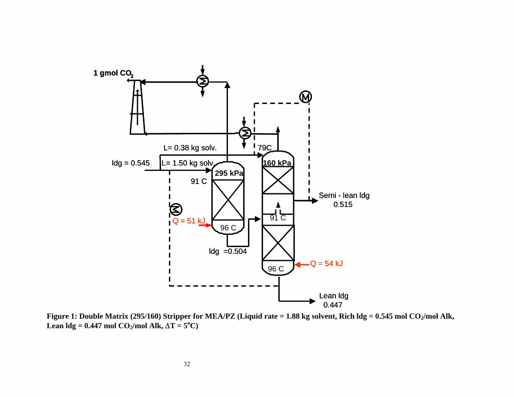
4.1 Matrix Stripper. In this two-stage matrix (Figure 1), the temperature change
across the stripper is reduced as in the multipressure configuration but without the
inefficiencies associated with mechanical compression. The rich solution from the
absorber is split into two streams. The first is sent to the first stripper at a higher pressure
resulting in a slightly superheated feed. Heat is applied in the form of reboiler steam. The
lean solution from the first column is the semi-rich feed to the middle of the second
column (which operates at a lower pressure). The other rich stream is fed to the top of the
second stripper. The second column produces a semi-lean and a lean stream. The semi-
lean stream is cross-exchanged with the rich feed to the second column while the lean
solution is cross-exchanged with the rich solution to the first stripper. The water vapor
from the overhead of the second column is condensed and the CO2 is sent to the first
stage of the compression train. The water vapor in the overhead from the first column is
condensed and the CO2 is sent to the second stage in the compression train.
The compression work in this configuration is reduced because some of the CO2 is
recovered at a higher pressure, therefore requiring less compression downstream. The
lower pressure column is set to 160 kPa for normal pressure operations and 30 kPa for
vacuum operations. The pressure of the higher-pressure column and the flow into the
flash section are optimized to minimize the total equivalent work of the system. Even
though a two-stage matrix is described in this work, a three-stage matrix can also be used
with reduced energy requirement but increased complexity.
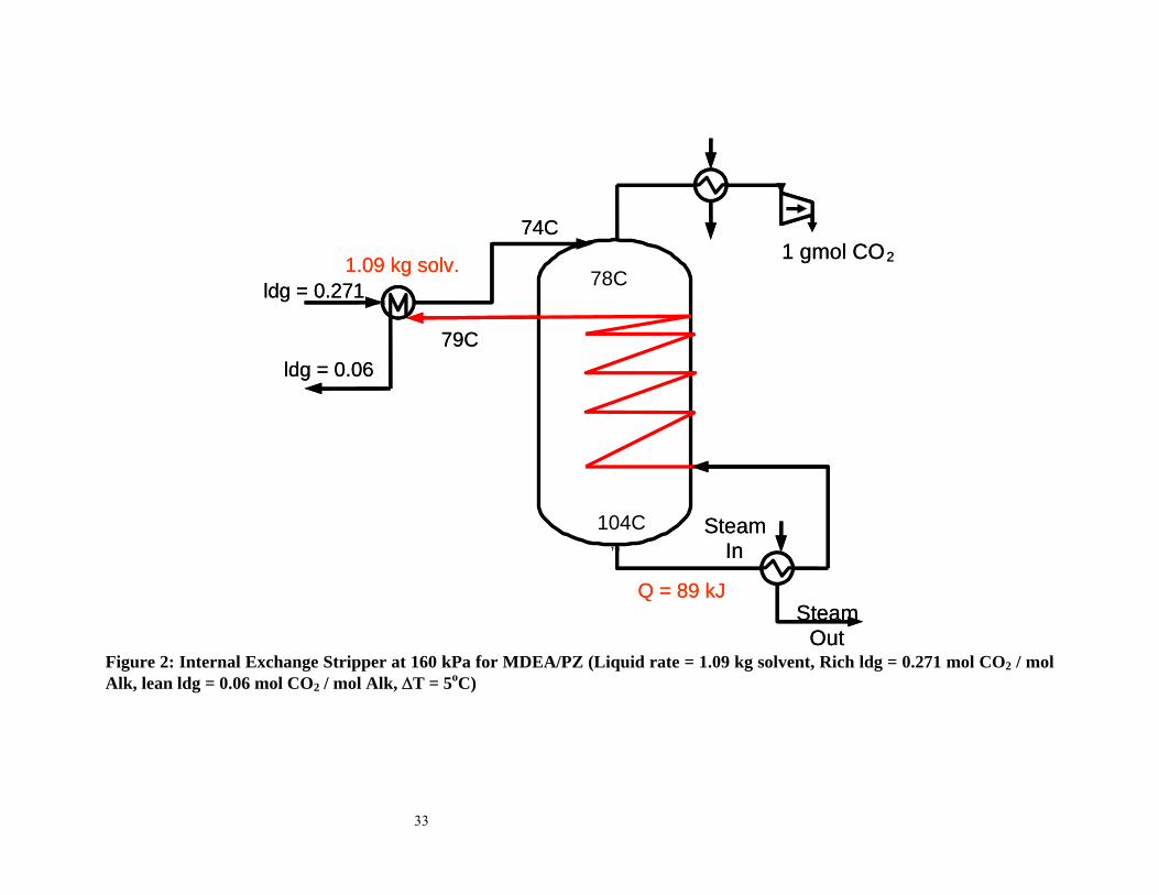
4.2 Internal Exchange Stripper. This configuration (Figure 2), integrates the stripping
process with heat transfer. It serves to approach the theoretical limit of adding and
removing material and energy streams along the entire column. This process has been
7
described by Leites et al.20 It is approximated in a configuration tested by Mitsubishi12.
The configuration alleviates the temperature drop across the stripper by exchanging the
hot lean solution with the solution in the stripper. One implementation would place
continuous heat exchange surface in the stripper so that there is countercurrent heat
exchange of the hot lean solution with the solution coming down the stripper. A large
overall heat transfer capability of 41.84 W/K-mol solvent per segment was used. This
gave a typical ∆T of 1.2 K and 3K in the internal exchanger for the vacuum operation and
for operation at normal pressure respectively.
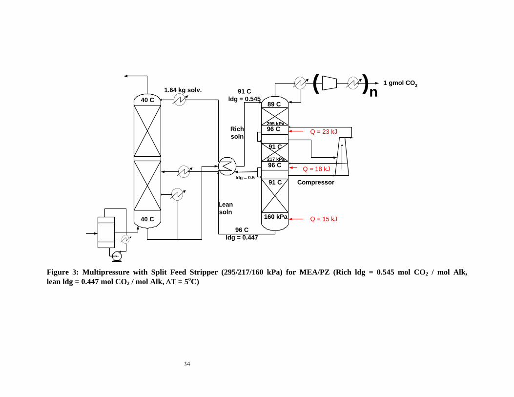
4.3 Multipressure with Split Feed. The multipressure configuration was described in
our previous work17, 19. This advanced configuration (Figure 3) takes a 10% split feed
from the liquid flowing from the middle to the lowest pressure level in a multipressure
stripper and sends this stream to an appropriate point in the absorber. The temperatures at
the bottom of the stripper pressure sections are equal and heat is added to each stripper
pressure section. This configuration takes advantage of the favorable characteristics of
the multipressure configuration and the split flow concepts. The top pressure has been
optimized for all solvents and configurations. The middle pressure was taken as the
geometric mean.
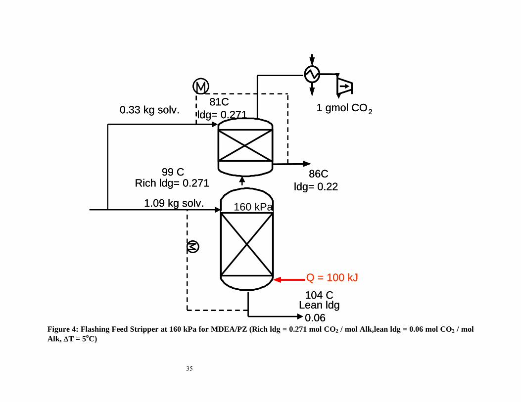
4.4 Flashing Feed Stripper. This configuration (Figure 4) is a special case of the split
flow concept described by Leites et al.20 and Aroonwilas31. A fraction of the rich stream
is sent to the middle of the stripper where stripping occurs and a lean solution exits at the
bottom. The rich solution is cross-exchanged with the lean solution exiting the stripper
bottom. The vapor leaving the stripper is then contacted with the absorber rich flow in a
five-staged upper section where the latent heat of water vapor is used to strip the CO2 in
8
the “cold feed” and a semi-lean stream is produced. The semi-lean product is cross-
exchanged with the rich solution fed to the upper section. The reboiler duty remains
unchanged and “free stripping” can be achieved in the upper section. The split ratio of the
rich streams into the middle and upper sections was optimized to minimize equivalent
work.
5. Model Development
An equilibrium stripper model for aqueous solvents developed in Aspen Custom
Modeler (ACM) was used to evaluate the different process configurations and solvents. A
rich end pinch is usually predicted because of the generous amount of contacting
assumed in the model. The stripper consisted of a flash region, ten segments with 40%
Murphree efficiency assigned to CO2, and a reboiler with 100% CO2 efficiency. The flash
region in the column was quantified in terms of actual section performance.
5.1 Modeling Assumptions.
The sections are well mixed in the liquid and vapor phases.
The reboiler is in vapor/liquid equilibrium.
There is negligible vaporization of the amine.
The CO2 vapor pressure (kPa) under stripper conditions for 7m MEA, promoted
MEA and different PZ/K2CO3 blends is represented by the empirical expression in Table
1.
The adjustable constants in Table 1 for the PZ/K2CO3 solutions were obtained by
regressing points from the rigorous thermodynamic model by Cullinane 2. The constants
for the MEA solvents were regressed from points obtained from equilibrium flashes in
AspenPlus using the Electrolyte Non Random Two Liquid (E-NRTL) model developed
by Freguia32 from data of Jou et al.33
9
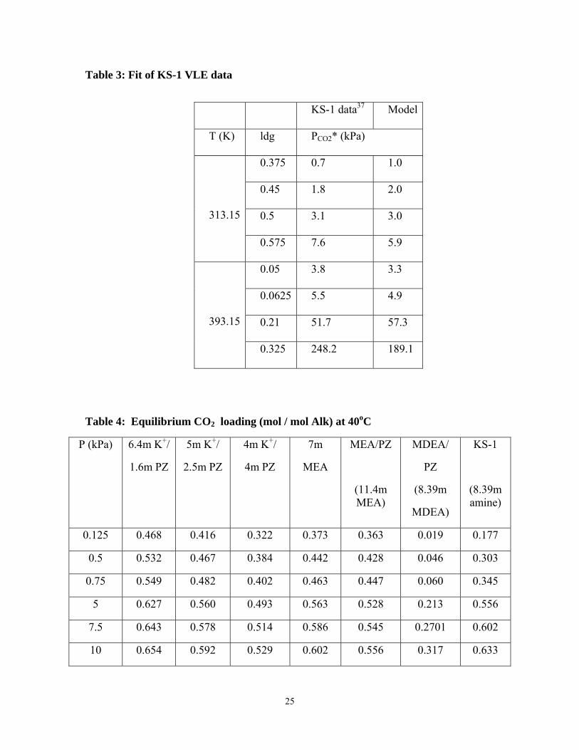
The CO2 vapor pressure over 4.28M MDEA and KS-1, based on the model by Posey
et al. 34 is shown in Table 2. For 4.28M MDEA, the constants in Table 2 are taken from
Posey et al. For KS-1 the constant, A, was set at 32.45 while constants, B-D, in the
equilibrium constant expression were adjusted to fit available data28. The amine mole
fraction shown in Table 2 for KS-1 is set at 0.1313. The fit of the KS-1 data is shown in
Table 3. The CO2 solubility in the different solvents at 40oC is shown in Table 4.
The heat of absorption/desorption was calculated by differentiating the equation in
Table 1 with respect to 1/T:
) f(T
2eT
2dcR∆H 2
γγγ
+++=− (2)
The heat of desorption for 4.28M MDEA and KS-1 was assumed to be constant at 62
and 73 kJ/gmol CO2 respectively. The heat of vaporization of water, partial pressure of
water, and heat capacities of solvent (assumed to be water), steam, and CO2 were
calculated with equations from the DIPPR database35. The molar heat capacities for the
CO2, water and amine were assumed to be equal and set to that of one mole of water.
The partial pressure of CO2 and water in each section was calculated by:
(3) 1( * )n n nmvP E P P P− −= − + 1n
A Murphree efficiency (Emv) of 40% and 100% was assigned to CO2 and water. The
model assumed that temperature equilibrium is achieved in each section.
The model inputs were the rich loading and liquid rate, the temperature approach on the
hot side of the cross exchanger (difference between the temperature of the rich stripper
feed and the lean solution leaving the bottom of the stripper), and column pressure. Initial
guesses of the lean loading, section temperatures, partial pressures, and loading were
provided. The model solves equations for calculating VLE and for material and energy
10
balances. It calculates temperature and composition profiles, reboiler duty, and equivalent
work.
The total energy required by the stripper is given as total equivalent work:
rebeq comp
reb
(T 10) 313W 0.75Q W(T 10)
⎡ ⎤+ −= +⎢ ⎥+⎣ ⎦
(4)
Wcomp constitutes the isentropic work of compression to 330 kPa of the gas exiting the
top of the stripper. An efficiency of 75% was assumed for the compressor. For the
vacuum operations, five compressor stages were used, while for the normal pressure
cases, three compressor stages were used. Two stages of compression were used to get to
the maximum pressure of the process and an additional stage to 330 kPa with intercooling
to 313K between compressor stages.
The work lost by extracting steam from a turbine is the first term on the right hand side
of (5), while the second is the compressor work. The condensing temperature of the
steam is assumed to be 10K higher than the reboiler fluid. The turbine assumes
condensing steam at 313K and has been assigned an effective Carnot efficiency of 75%.
6. Results and Discussion
Table 5 gives the performance (stripping and compression work to 330 kPa) of the
stripper configurations investigated and the capacities of the solvents to achieve 90% CO2
removal. The rich PCO2* shown in the table are typical rich partial pressures expected for
the solvents investigated. 4m K+/4m PZ, MEA/PZ, and MDEA/PZ are assigned greater
rich PCO2* because they are solvents with faster rates of reaction with CO2 which result in
richer solutions. In this work, the lean loading for each configuration was optimized to
minimize equivalent work. The optimum lean loading, the lean loading that minimized
equivalent work, was quite flat and was approximately that for 90% change in
11
equilibrium partial pressure of CO2. The lean loading and results shown in Table 5
correspond to a 90% equilibrium partial pressure change in CO2 at 40oC. The 10oC
approach cases were optimized with respect to lean loading as these usually give more
capacity for absorption.
The heat of absorption shown in Table 5 is that calculated at the lean loading and 40oC.
The capacity of the solution is given by:
( )OHkg
Alkmol - γOHkg
COmolcapacity2
leanrich2
2 γ=⎟⎟⎠
⎞⎜⎜⎝
⎛ (5)
6.1 Effect of varying temperature approach. The baseline configuration is a stripper
operating at 160 kPa with a 10oC approach on the hot side of the cross exchanger. The
lean loadings for the baseline were optimized and frequently resulted in overstripping to
increase the capacity of the solvents for absorption. With a 5oC approach on the hot side
of the cross exchanger, 3% and 12% energy savings are obtained for the 6.4m K+/1.6m
PZ and 7m MEA solvents respectively. This savings in energy is at the expense of a
larger investment in heat exchange surface.
6.2 Effect of operating pressure. Operating the stripper under vacuum (30 kPa) with a
5oC temperature approach in the cross exchanger offers a 14% reduction in equivalent
work for 6.4m K+/1.6m PZ and 4% and 20% more energy with 5m K+/2.5m PZ and
MEA/PZ respectively. This shows that vacuum operation favors solvents with low heats
of absorption while operation at normal pressure favors solvents with high heats of
absorption. Solvents with high heats of absorption take advantage of the temperature
swing. The relative vapor pressure of CO2 and water changes with temperature. This
change is greater with solvents with high heats of absorption as shown in Table 6.
12
The reboiler duty required for stripping can be approximated as the sum of three terms:
the heat required to desorb the CO2, that required to generate the water vapor at the top of
the column, and the sensible heat requirement.
Q = Qdes + QH2O gen. + Qsens (6)
⎟⎟⎠
⎞⎜⎜⎝
⎛ ∆+⎟⎟
⎠
⎞⎜⎜⎝
⎛+∆=
CO2vap
CO2
H2Odes n
TCpLHnn
H (7)
Table 6 shows the contributions to the reboiler duty for 6.4m K+/1.6m PZ and MEA/PZ
with ∆Hdes of 50 and 85 kJ/gmol CO2 respectively. The major difference between the
reboiler duties is the relative amount of the heat of desorption of CO2 and the heat
required to generate the water vapor at the top of the stripper. Vacuum operation for a
fixed solvent and CO2 removal generates a larger amount of water vapor at the top of the
column relative to operation at normal pressure. The overall effect is that vacuum
operation favors solvents with low heats of desorption and normal pressure favors
solvents with high heats of desorption.
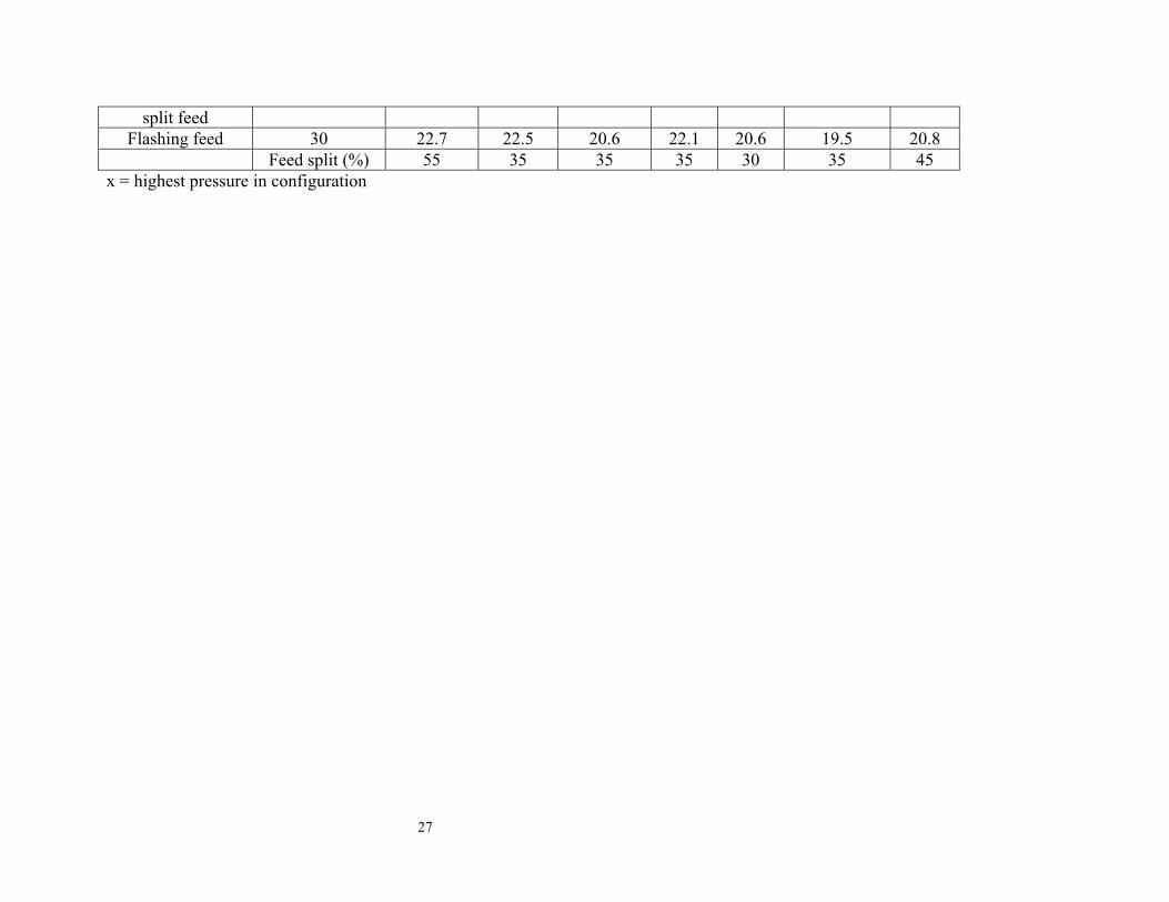
6.3 Predicted Performance of Alternative Configurations. Table 5 shows that the
multipressure configuration with a 160 kPa reboiler is more attractive for the solvents
with a high heat of absorption than solvents with a lower heat of absorption. The
performance of the alternative configurations is matrix > internal exchange >
multipressure with split feed > flashing feed. The matrix and internal exchange
configurations with a 160 kPa reboiler and 5oC approach with 7m MEA offer 9% and
11% energy savings respectively over the simple stripper operated at 160 kPa with a 5oC
approach.
The characteristics of the matrix (265/160 kPa) and 160 kPa strippers for MEA are
shown in Table 7. The matrix stripper recovers about 40% of the CO2 at a higher pressure
13
and does not have the inefficiencies associated with the multipressure stripper. The
reboiler duty is also slightly less for the matrix than the vacuum stripper.
The characteristics of the vacuum and the vacuum internal exchange strippers are
shown in Table 8. The major difference between the two configurations is the difference
in the ratio of the water vapor to CO2 in the overhead stream. The internal exchange
stripper has a smaller ratio of water vapor to CO2. Multipressure with split feed reduces
the flow into the bottom section of the stripper and thus equivalent work. The flashing
feed makes use of the latent heat of water vapor in the simple/vacuum configuration to
strip some CO2 in the rich stream entering the stripper at the top of the column.
6.4 Solvent Performance. Table 5 shows the performance of the different solvent
types. The results show that at 160 kPa, MEA/PZ and MDEA/PZ require significantly
less equivalent work than 7m MEA. MEA/PZ offers a 13% and 8% savings over 7m
MEA with the matrix and internal exchange configurations at 160 kPa. MDEA/PZ was
the most attractive solvent under vacuum conditions. MDEA/PZ offers a 14% and 10%
savings over 7m MEA with the matrix and internal exchange configurations at 30 kPa.
This shows that, at normal pressure, solvents with high heats of absorption and
reasonable capacities are attractive. Under vacuum conditions, solvents with lower heats
of absorption and higher capacities are attractive. Capacity seems to play a more
important role in determining energy requirements at vacuum conditions.
6.5 Effect of heat of absorption. From Table 5, solvents with similar capacities but
different heats of absorption can be compared. 6.4m K+/1.6m PZ and 5m K+/2.5m PZ are
compared. The results show that at a fixed capacity, solvents with high heats of
absorption require less energy for stripping. This is a consequence of the temperature
14
swing. The 5m K+/2.5m PZ offers 18% savings over 6.4m K+/1.6m PZ at 160 kPa with a
5oC approach and savings of 3% and 4% with the matrix and internal exchange
configurations at vacuum conditions.
6.6 Effect of capacity. The capacity of a solvent is defined as the amount of CO2 a
solvent can absorb over a given range of loading or partial pressure. This reflects the
vapor-liquid equilibrium characteristics of a solvent. A high capacity solvent can absorb
or desorb more CO2 than one with a low capacity. In Table 5, 5m K+/2.5m PZ and
MDEA/PZ have similar heats of absorption however MDEA/PZ has a greater capacity
than 5m K+/2.5m PZ. MDEA/PZ provides 30% and 19% energy savings over 5m
K+/2.5m PZ with the matrix and internal exchange configurations with the reboiler
operating at 160 kPa and 17% and 12% savings with these configurations at 30 kPa. The
two MEA solvents also have similar heats of absorption. MEA/PZ represented by 11.4 m
MEA has a higher capacity than 7m MEA. MEA/PZ offers 13% energy savings over 7m
MEA with the matrix stripper operated with a 160 kPa reboiler temperature.
6.7 Insight into stripper operation. McCabe-Thiele plots provide insight into
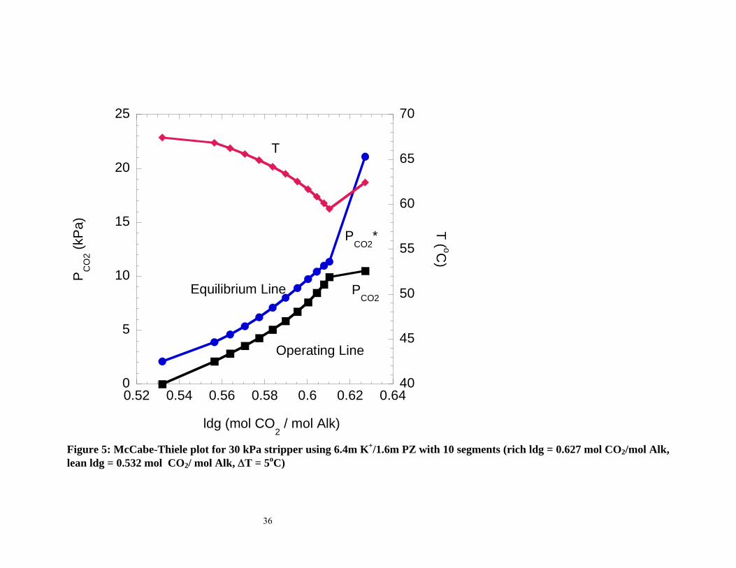
stripping phenomena. Figure 5 shows the McCabe-Thiele plot for 6.4m K+/1.6m PZ at 30
kPa comprising of a flash section, ten segments, and an equilibrium reboiler. The stripper
operation approaches a lean end pinch. Since this column is not pinched, it could benefit
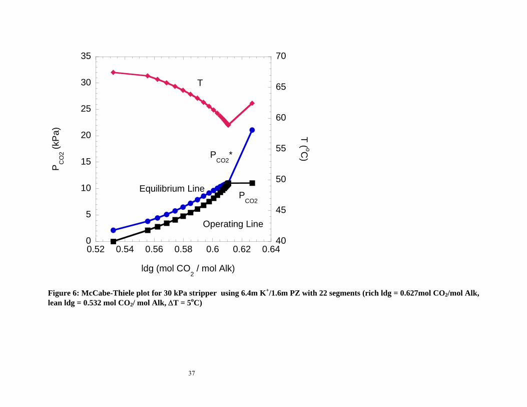
significantly by using more contacting. This is shown in Figure 6 where the number of
contacting segments is doubled. Flashing of the rich solution occurs at the top of the
column. A rich end pinch is observed. The total equivalent work to generate CO2 at 330
kPa decreases from 23.2 kJ/gmol CO2 with ten segments to 23.2 kJ/gmol CO2 (a 2%
15
reduction) when the number of segments is doubled. Increasing the number of segments
implies increased capital cost.
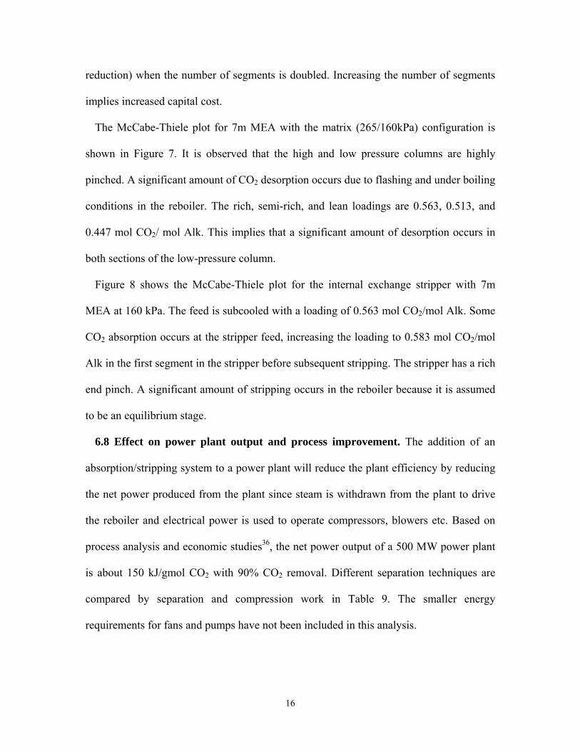
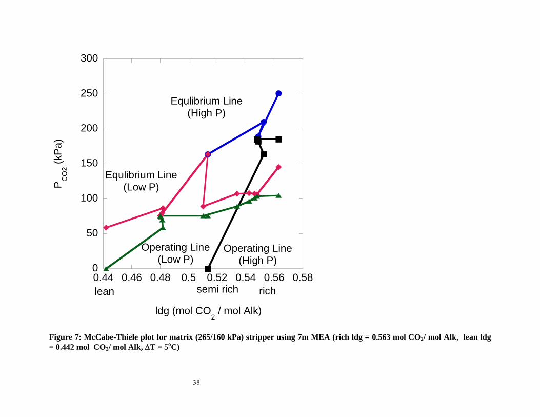
The McCabe-Thiele plot for 7m MEA with the matrix (265/160kPa) configuration is
shown in Figure 7. It is observed that the high and low pressure columns are highly
pinched. A significant amount of CO2 desorption occurs due to flashing and under boiling
conditions in the reboiler. The rich, semi-rich, and lean loadings are 0.563, 0.513, and
0.447 mol CO2/ mol Alk. This implies that a significant amount of desorption occurs in
both sections of the low-pressure column.
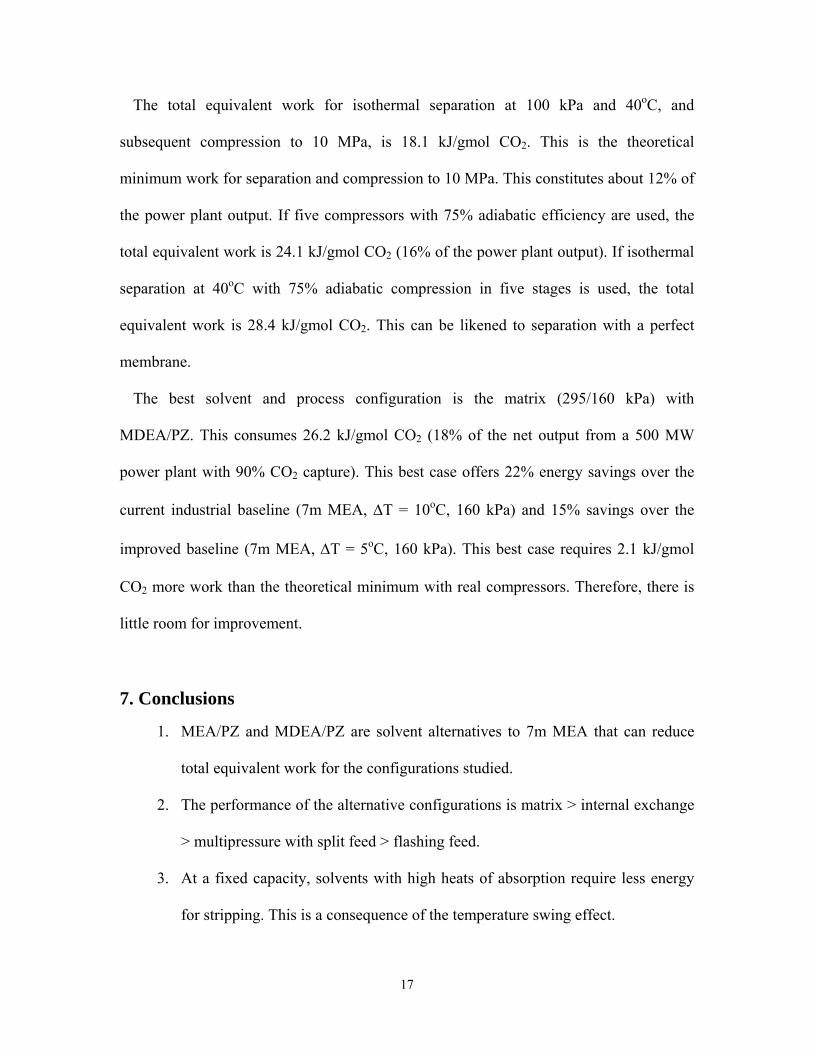
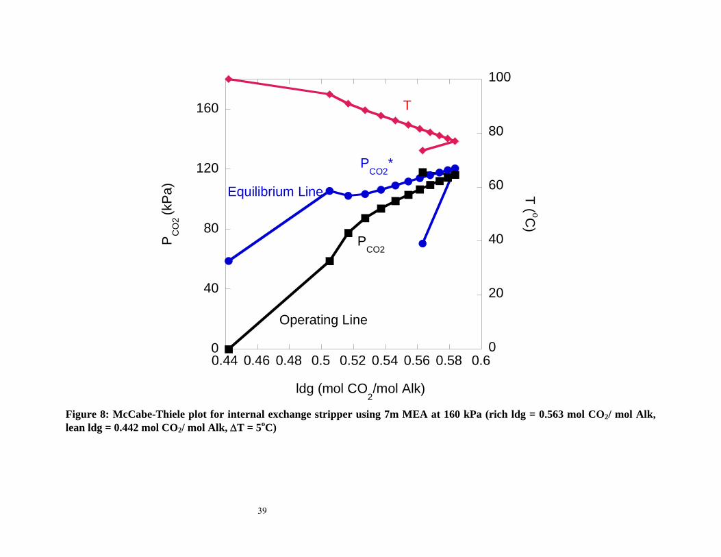
Figure 8 shows the McCabe-Thiele plot for the internal exchange stripper with 7m
MEA at 160 kPa. The feed is subcooled with a loading of 0.563 mol CO2/mol Alk. Some
CO2 absorption occurs at the stripper feed, increasing the loading to 0.583 mol CO2/mol
Alk in the first segment in the stripper before subsequent stripping. The stripper has a rich
end pinch. A significant amount of stripping occurs in the reboiler because it is assumed
to be an equilibrium stage.
6.8 Effect on power plant output and process improvement. The addition of an
absorption/stripping system to a power plant will reduce the plant efficiency by reducing
the net power produced from the plant since steam is withdrawn from the plant to drive
the reboiler and electrical power is used to operate compressors, blowers etc. Based on
process analysis and economic studies36, the net power output of a 500 MW power plant
is about 150 kJ/gmol CO2 with 90% CO2 removal. Different separation techniques are
compared by separation and compression work in Table 9. The smaller energy
requirements for fans and pumps have not been included in this analysis.
16
The total equivalent work for isothermal separation at 100 kPa and 40oC, and
subsequent compression to 10 MPa, is 18.1 kJ/gmol CO2. This is the theoretical
minimum work for separation and compression to 10 MPa. This constitutes about 12% of
the power plant output. If five compressors with 75% adiabatic efficiency are used, the
total equivalent work is 24.1 kJ/gmol CO2 (16% of the power plant output). If isothermal
separation at 40oC with 75% adiabatic compression in five stages is used, the total
equivalent work is 28.4 kJ/gmol CO2. This can be likened to separation with a perfect
membrane.
The best solvent and process configuration is the matrix (295/160 kPa) with
MDEA/PZ. This consumes 26.2 kJ/gmol CO2 (18% of the net output from a 500 MW
power plant with 90% CO2 capture). This best case offers 22% energy savings over the
current industrial baseline (7m MEA, ∆T = 10oC, 160 kPa) and 15% savings over the
improved baseline (7m MEA, ∆T = 5oC, 160 kPa). This best case requires 2.1 kJ/gmol
CO2 more work than the theoretical minimum with real compressors. Therefore, there is
little room for improvement.
7. Conclusions
1. MEA/PZ and MDEA/PZ are solvent alternatives to 7m MEA that can reduce
total equivalent work for the configurations studied.
2. The performance of the alternative configurations is matrix > internal exchange
> multipressure with split feed > flashing feed.
3. At a fixed capacity, solvents with high heats of absorption require less energy
for stripping. This is a consequence of the temperature swing effect.
17
4. Less energy is required with high capacity solvents with equivalent heat of
absorption.
5. The typical predicted energy requirement for stripping and compression to 10
MPa (30 kJ/gmol CO2) is about 20% of the power output from a 500 MW
power plant with 90% CO2 removal.
6. The best solvent and process configuration in this study, matrix (295/160) using
MDEA/PZ, offers 22% energy savings over the baseline and 15% savings over
the improved baseline with stripping and compression to 10 MPa.
Acknowledgements
Aspen Technology provided the AspenPlus and Aspen Custom Modeler software. This
paper was prepared with the support of the U.S. Department of Energy, under Award No.
DE-FC26-02NT41440. However, any opinions, findings, conclusions, or recommenda-
tions expressed herein are those of the authors and do not necessarily reflect the views of
the DOE.
Nomenclature
∆T = Temperature approach in cross exchanger [K]
γ = CO2 loading [mol CO2/(mol MEA + mol K+ + mol 2 PZ + mol MDEA +
mol KS-1)]
Cp = heat capacity of liquid [kJ/mol-K]
Emv = Murphree section efficiency defined in terms of partial pressures [-]
gCO2 = mole rate of CO2 [gmoles/s]
18
∆H = heat of absorption/desorption [kJ/gmol CO2]
Hvap = heat of vaporization of water [45 kJ/mol]
KCO2 = equilibrium constant for CO2 [kPa]
L = Liquid rate [gmoles/s]
ldg = [mol CO2/(mol MEA + mol K+ + mol 2 PZ + mol MDEA +
mol KS-1)]
mol Alk = [mol MEA + mol K+ + mol 2 PZ + mol MDEA + mol KS-1]
nCO2 = mole of CO2 [moles]
nH2O = mole of H2O [moles]
PCO2 = partial pressure of CO2 in the bulk gas [kPa]
PCO2* = equilibrium partial pressure of CO2 [kPa]
Pn = partial pressures on sections n [kPa]
Pn-1 = partial pressures sections n-1 [kPa]
Pn* = equilibrium partial pressure leaving section n [kPa]
Q = reboiler duty [kJ/gmol CO2]
Qdes = Heat of desorption of CO2 [kJ/gmol CO2]
QH2O,gen = Heat of steam generation [kJ/gmol CO2]
Qsens = Sensible heat required to heat rich solution to reboiler
temperature [kJ/gmol CO2]
R = universal gas constant [J/K-mol]
T = temperature [K]
Wcomp = isentropic work of compression [kJ/gmol CO2]
Weq = equivalent work [kJ/gmol CO2]
19
Xoamine = CO2 free amine mole fraction [mol amine / (mol amine + mol H2O)]
XCO2 = CO2 liquid mole fraction [mol CO2/(mol amine + mol CO2 + mol H2O)]
20
References
1. Rochelle, G. T. In Innovative Stripper Configurations to Reduce the Energy Cost of CO2 Capture, Second Annual Carbon Sequestration Conference, Alexandria, VA, 2003; Alexandria, VA, 2003. 2. Cullinane, J. T. Thermodynamics and Kinetics of aqueous piperazine with potassium carbonate for carbon dioxide absorption. Ph.D Dissertation, University of Texas-Austin, Austin, 2005. 3. Cullinane, J. T. Carbon Dioxide absorption in aqueous mixtures of potassium carbonate and piperazine. M.S. Thesis, University of Texas-Austin, Austin, 2002. 4. Cullinane, J. T.; Oyenekan, B. A.; Lu, J.; Rochelle, G. T. In Aqueous piperazine/potassium carbonate for enhanced CO2 capture, 7th International Conference on Greenhouse Gas Control Technologies. Volume 1: Peer-Reviewed Papers and Plenary Presentations, IEA Greenhouse Gas Programme, Cheltenham, UK, 2004., E.S.Rubin; D.W.Keith; C.F.Gilboy, Eds. 5. Cullinane, J. T.; Rochelle, G. T., Thermodynamics of Aqueous Potassium Carbonate, Piperazine, and CO2 Mixtures. Fluid Phase Equilibrium 2004, 227, 197-213. 6. Dang, H. CO2 absorption rate and solubility in monoethanolamine/piperazine/water. M.S. Thesis, University of Texas-Austin, Austin, 2000. 7. Okoye, C. I. Carbon dioxide solubility and absorption rate in monoethanolamine/piperazine/water. M.S. Thesis, The University of Texas at Austin, Austin, 2005. 8. Bishnoi, S. Carbon Dioxide Absorption and solution equilibrium in piperazine activated methyldiethanolamine. Ph.D. Dissertation, University of Texas-Austin, Austin, 2000. 9. Aroonwilas, A.; Veawab, A., Cost,energy consumption and performance of CO2 capture process using MEA-MDEA and DEA-MDEA. In 8th International Conference on Greenhouse Gas Control Technologies, Trondheim, Norway, 2006. 10. Idem, R.; Wilson, M.; Tontiwachwuthikul, P.; Chakma, A.; Veawab, A.; Aroonwilas, A.; Gelowitz, D., Pilot Plant Studies of the CO2 Capture Performance of Aqueous MEA and Mixed MEA/MDEA Solvents at the University of Regina CO2 Capture Technology Development Plant and the Boundary Dam CO2 Capture Demonstration Plant. Ind. Eng. Chem. Res. 2006, 45, 2414-2420. 11. Mimura, T.; Simayoshi, H.; Suda, T.; Iijima, M.; Mituoka, S., Development of energy saving technology for flue gas carbon dioxide recovery in power plant by chemical absorption method and steam system. Energy Conversion and Management 1997, 38, (Suppl., Proceedings of the Third International Conference on Carbon Dioxide Removal, 1996), S57-S62. 12. Yagi, Y.; Mimura, T.; Yonekawa, T.; Yoshiyama, R., Development and improvement of CO2-capture system. In 8th International Conference on Greenhouse Gas Control Technologies, Trondheim, Norway, 2006. 13. Bullin, J. A.; Polasek, J. C.; Donnelly, S. T., How to reduce costs in amine-sweetening units. Chemical Engineering Progress 1983, 79, (3), 63-7. 14. Polasek, J. C.; Bullin, J. A.; Donnelly, S. T., Alternative Flow Shemes to Reduce Capital and Operating Costs of Amine Sweetening Units. Energy Processing/Canada 1982, 74, (5), 45-50.
21
15. Aroonwilas, A. In Evaluation of split-flow scheme for CO2 absorption process using mechanistic mass-transfer and hydrodynamic model, 7th International Conference on Greenhouse Gas Control Technologies. Volume 1: Peer-Reviewed Papers and Plenary Presentations, IEA Greenhouse Gas Programme, Cheltenham, UK, 2004., E.S.Rubin; D.W.Keith; C.F.Gilboy, Eds. 16. Aroonwilas, A.; Veawab, A., Cost structure and performance of CO2 capture unit using split-stream cycle In 8th International Conference on Greenhouse Gas Control Technologies, Trondheim, Norway, 2006. 17. Oyenekan, B. A.; Rochelle, G. T., Energy Performance of Stripper Configurations for CO2 Capture by Aqueous Amines. Ind Eng Chem Res 2006, 45, (8), 2457-64. 18. Oyenekan, B. A.; Rochelle, G. T., Modeling of Innovative Stripper Concepts. In 8th International Post Combustion CO2 Capture Network Meeting, Austin,Texas, USA, 2005. 19. Jassim, M. S.; Rochelle, G. T., Innovative Absorber/Stripper Configurations for CO2 Capture by Aqueous Monoethanolamine. Industrial & Engineering Chemistry Research 2006, 45, (8), 2465-72. 20. Leites, I. L.; Sama, D. A.; Lior, N., The Theory and Practice of Energy Saving in the Chemical Industry: Some Methods for Reducing Thermodynamic Irreversibility in Chemical Technology Processes. Energy (Oxford, United Kingdom) 2003, 28, (1), 55-97. 21. Chen, E.; Rochelle, G. T.; Seibert, F., Pilot plant for CO2 capture with aqueous piperazine/potassium carbonate. In 8th International Conference on Greenhouse Gas Control Technologies Trondheim,Norway, 2006. 22. Dang, H.; Rochelle, G. T., CO2 absorption rate and solubility in MEA/PZ/H2O. Sep. Sci. Tech. 2003, 38, (2), 337-357. 23. Bishnoi, S.; Rochelle, G. T., Absorption of CO2 in aqueous PZ/MDEA. AIChE J. 2002, 48, (12), 2788-2799. 24. Bishnoi, S.; Rochelle, G. T., Thermodynamics of PZ/MDEA/H2O/CO2. Ind Eng Chem Res 2002, 41, (3), 604-612. 25. Appl, M. Removal of CO2 and/or H2S and/or COS from gases containing these constituents. U.S.P.N. 4.336,233, 1982. 26. Sartori, G.; Savage, D. W., Sterically hindered amines for carbon dioxide removal from gases. Industrial & Engineering Chemistry Fundamentals 1983, 22, (2), 239-49. 27. Sartori, G.; Savage, D. W., Sterically Hindered Amines for CO2 Removal from Gases. Industrial & Engineering Chemistry Fundamentals 1983, 22, (2), 239-249. 28. Suzuki, H.; Iwaki, T.; Mitsuoka, S.; Tanaka, H.; Iijima, M. Method for the removal of carbon dioxide present in gases. U.S.P.N. 5,904,908, 1999. 29. Sartori, G.; Ho, W. S.; Savage, D. W.; Chludzinski, G. R.; Wiechert, S., Sterically Hindered Amines for Acid-Gas Absorption. Separation and Purification Methods 1987, 16, (2), 171-200. 30. Imai, N.; Ishida, K. In Economic Study on CO2 Capture and Sequestration from PCF Flue Gas, 7th International Conference on Greenhouse Gas Control Technology, Vancouver,Canada,2004 31. Aroonwilas, A., Evaluation of split-flow scheme for CO2 absorption process using mechanistic mass-transfer and hydrodynamic model. In 7th International Conference on Greenhouse Gas Control Technologies, Vancouver, Canada, 2004.
22
32. Freguia, S. Modeling of CO2 removal from Flue Gas with Monoethanolamine. M.S. Thesis, University of Texas-Austin, Austin, 2002. 33. Jou, F.-Y.; Mather, A. E.; Otto, F. D., The Solubility of CO2 in a 30 Mass Percent Monoethanolamine Solution. The Canadian Journal of Chemical Engineering 1995, 73, (1), 140-147. 34. Posey, M. L.; Tapperson, K. G.; Rochelle, G. T., A simple model for prediction of acid gas solubilities in alkanolamines. Gas. Sep. Purif. 1996, 10, (3), 181-186. 35. American Institute of Chemical Engineers, Design Institute for Physical Properties In 2004. 36. Fisher, K. S.; Beitler, C.; Rueter, C.; Rochelle, G. T.; Jassim, M. S. Integrating MEA regeneration with CO2 compression and peaking to reduce CO2 capture costs; DOE Final Report for Trimeric Corp. subcontract of DOE contract #DE-FG02-04ER84111: 2005. 37. Mitsubishi Heavy Industries, Flue gas CO2 recovery. Trade Publication.
23
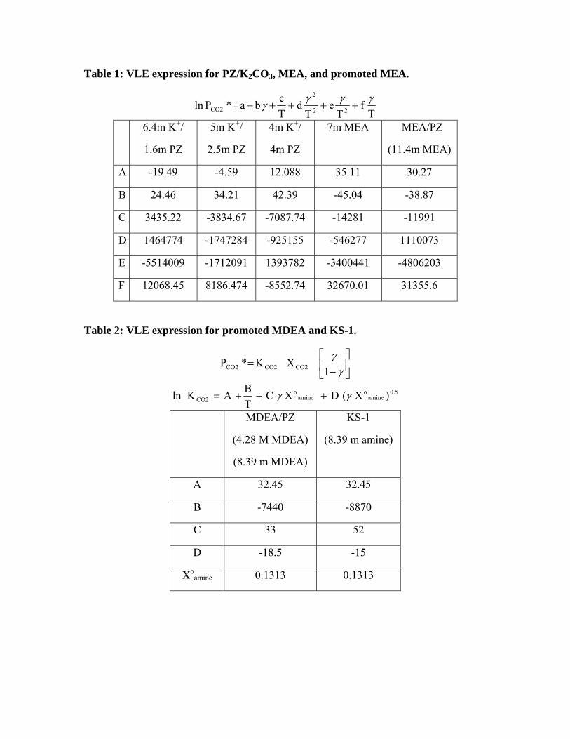
Table 1: VLE expression for PZ/K2CO3, MEA, and promoted MEA.
Tf
Te
Td
Tcba*Pln 22
2
CO2γγγγ +++++=
6.4m K+/
1.6m PZ
5m K+/
2.5m PZ
4m K+/
4m PZ
7m MEA MEA/PZ
(11.4m MEA)
A -19.49 -4.59 12.088 35.11 30.27
B 24.46 34.21 42.39 -45.04 -38.87
C 3435.22 -3834.67 -7087.74 -14281 -11991
D 1464774 -1747284 -925155 -546277 1110073
E -5514009 -1712091 1393782 -3400441 -4806203
F 12068.45 8186.474 -8552.74 32670.01 31355.6
Table 2: VLE expression for promoted MDEA and KS-1.
⎥⎦
⎤⎢⎣
⎡−
=γ
γ1
XK*P CO2CO2CO2
0.5amine
oamine
oCO2 )X (DXC
TBAKln γγ +++=
MDEA/PZ
(4.28 M MDEA)
(8.39 m MDEA)
KS-1
(8.39 m amine)
A 32.45 32.45
B -7440 -8870
C 33 52
D -18.5 -15
Xoamine 0.1313 0.1313
P (kPa) 6.4m K+/
1.6m PZ
5m K+/
2.5m PZ
4m K+/
4m PZ
7m
MEA
MEA/PZ
(11.4m MEA)
MDEA/
PZ
(8.39m
MDEA)
KS-1
(8.39m amine)
0.125 0.468 0.416 0.322 0.373 0.363 0.019 0.177
0.5 0.532 0.467 0.384 0.442 0.428 0.046 0.303
0.75 0.549 0.482 0.402 0.463 0.447 0.060 0.345
5 0.627 0.560 0.493 0.563 0.528 0.213 0.556
7.5 0.643 0.578 0.514 0.586 0.545 0.2701 0.602
10 0.654 0.592 0.529 0.602 0.556 0.317 0.633
25
Table 4: Equilibrium CO2 loading (mol / mol Alk) at 40oC
Table 3: Fit of KS-1 VLE data
KS-1 data37 Model
T (K) ldg PCO2* (kPa)
0.375 0.7 1.0
0.45 1.8 2.0
0.5 3.1 3.0
313.15
0.575 7.6 5.9
0.05 3.8 3.3
0.0625 5.5 4.9
0.21 51.7 57.3
393.15
0.325 248.2 189.1
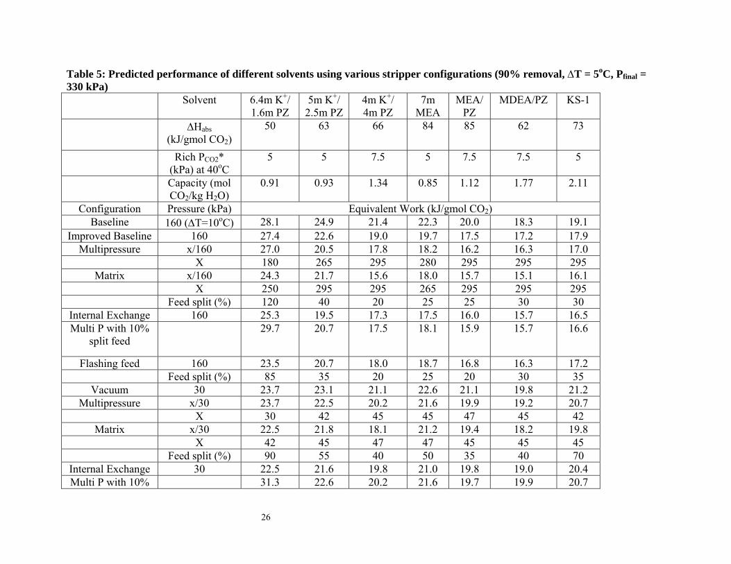
Table 5: Predicted performance of different solvents using various stripper configurations (90% removal, ∆T = 5oC, Pfinal = 330 kPa)
Solvent 6.4m K 5m K+/ 1.6m PZ
+/ 2.5m PZ
4m K+/ 4m PZ
7m MEA
MEA/PZ
MDEA/PZ KS-1
∆Habs(kJ/gmol CO2)
50 63 66 84 85 62 73
Rich PCO2* (kPa) at 40oC
5 5 7.5 5 7.5 7.5 5
Capacity (molCO
0.912/kg H2O)
0.93 1.34 0.85 1.12 1.77 2.11
Configuration Pressure (kPa) Equivalent Work (kJ/gmol CO2) Baseline 160 (∆T=10oC) 28.1 24.9 21.4 22.3 20.0 18.3 19.1
Improved Baseline 160 27.4 22.6 19.0 19.7 17.5 17.2 17.9Multipressure x/160 27.0 20.5 17.8 18.2 16.2 16.3 17.0
X 180 265 295 280 295 295 295Matrix x/160 24.3 21.7 15.6 18.0 15.7 15.1 16.1
X 250 295 295 265 295 295 295 Feed split (%) 120 40 20 25 25 30 30
Internal Exchange 160 25.3 19.5 17.3 17.5 16.0 15.7 16.5Multi P with 10%
split feed 29.7 20.7 17.5 18.1 15.9 15.7 16.6
Flashing feed 160 23.5 20.7 18.0 18.7 16.8 16.3 17.2 Feed split (%) 85 35 20 25 20 30 35
Vacuum 30 23.7 23.1 21.1 22.6 21.1 19.8 21.2Multipressure x/30 23.7 22.5 20.2 21.6 19.9 19.2 20.7
X 30 42 45 45 47 45 42Matrix x/30 22.5 21.8 18.1 21.2 19.4 18.2 19.8
X 42 45 47 47 45 45 45 Feed split (%) 90 55 40 50 35 40 70
Internal Exchange 30 22.5 21.6 19.8 21.0 19.8 19.0 20.4Multi P with 10% 31.3 22.6 20.2 21.6 19.7 19.9 20.7
26
split feed Flashing feed 30 22.7 22.5 20.6 22.1 20.6 19.5 20.8
Feed split (%) 55 35 35 35 30 35 45x = highest pressure in configuration
27
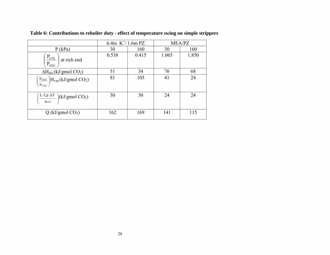
Table 6: Contributions to reboiler duty - effect of temperature swing on simple strippers
6.4m K+/ 1.6m PZ MEA/PZ P (kPa) 30 160 30 160
⎟⎟⎠
⎞⎜⎜⎝
⎛
H2O
CO2
PP
at rich end 0.538 0.415 1.065 1.850
∆Hdes (kJ/gmol CO2) 51 34 76 68
⎟⎟⎠
⎞⎜⎜⎝
⎛
CO2
H2O
nn Hvap (kJ/gmol CO2) 81 105 41 24
⎟⎟⎠
⎞⎜⎜⎝
⎛ ∆
CO2nTCpL (kJ/gmol CO2) 30 30 24 24
Q (kJ/gmol CO2) 162 169 141 115
28
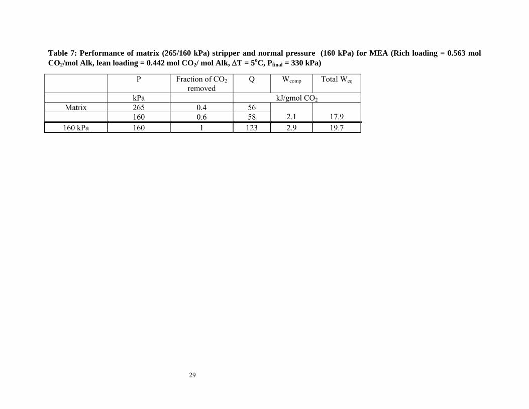
Table 7: Performance of matrix (265/160 kPa) stripper and normal pressure (160 kPa) for MEA (Rich loading = 0.563 mol CO2/mol Alk, lean loading = 0.442 mol CO2/ mol Alk, ∆T = 5oC, Pfinal = 330 kPa)
P Fraction of CO2 removed
Q Wcomp Total Weq
kPa kJ/gmol CO2Matrix 265 0.4 56
160 0.6 58
2.1
17.9 160 kPa 160 1 123 2.9 19.7
29
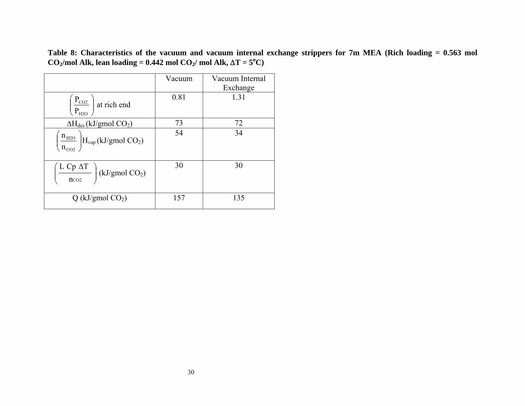
Table 8: Characteristics of the vacuum and vacuum internal exchange strippers for 7m MEA (Rich loading = 0.563 mol CO2/mol Alk, lean loading = 0.442 mol CO2/ mol Alk, ∆T = 5oC)
Vacuum Vacuum InternalExchange
⎟⎟⎠
⎞⎜⎜⎝
⎛
H2O
CO2
PP
at rich end 0.81 1.31
∆Hdes (kJ/gmol CO2) 73 72
⎟⎟⎠
⎞⎜⎜⎝
⎛
CO2
H2O
nn
Hvap (kJ/gmol CO2) 54 34
⎟⎟⎠
⎞⎜⎜⎝
⎛ ∆
CO2nTCpL
(kJ/gmol CO2) 30 30
Q (kJ/gmol CO2) 157 135
30
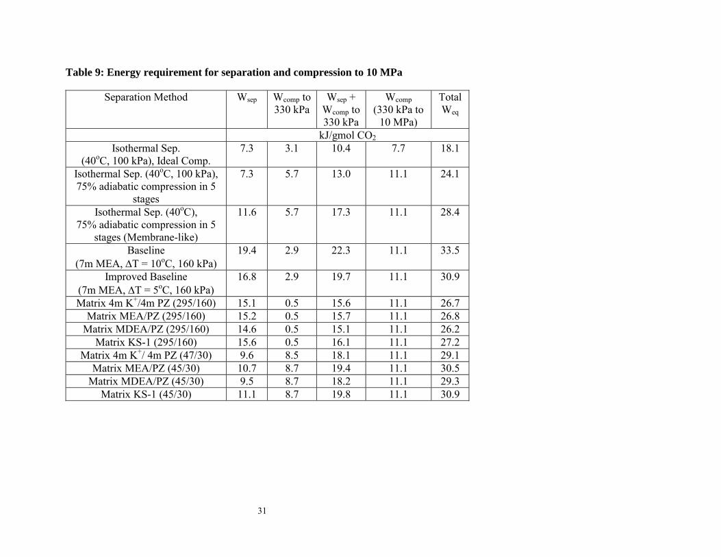
Table 9: Energy requirement for separation and compression to 10 MPa
Separation Method Wsep Wcomp to 330 kPa
Wsep + Wcomp to 330 kPa
Wcomp (330 kPa to
10 MPa)
Total Weq
kJ/gmol CO2 Isothermal Sep.
(40oC, 100 kPa), Ideal Comp. 7.3 3.1 10.4 7.7 18.1
Isothermal Sep. (40oC, 100 kPa), 75% adiabatic compression in 5
stages
7.3 5.7 13.0 11.1 24.1
Isothermal Sep. (40oC), 75% adiabatic compression in 5
stages (Membrane-like)
11.6 5.7 17.3 11.1 28.4
Baseline (7m MEA, ∆T = 10oC, 160 kPa)
19.4 2.9 22.3 11.1 33.5
Improved Baseline (7m MEA, ∆T = 5oC, 160 kPa)
16.8 2.9 19.7 11.1 30.9
Matrix 4m K+/4m PZ (295/160) 15.1 0.5 15.6 11.1 26.7 Matrix MEA/PZ (295/160) 15.2 0.5 15.7 11.1 26.8
Matrix MDEA/PZ (295/160) 14.6 0.5 15.1 11.1 26.2 Matrix KS-1 (295/160) 15.6 0.5 16.1 11.1 27.2
Matrix 4m K+/ 4m PZ (47/30) 9.6 8.5 18.1 11.1 29.1 Matrix MEA/PZ (45/30) 10.7 8.7 19.4 11.1 30.5
Matrix MDEA/PZ (45/30) 9.5 8.7 18.2 11.1 29.3 Matrix KS-1 (45/30) 11.1 8.7 19.8 11.1 30.9
31
ldg = 0.545295 kPa
160 kPa
1 gmol CO2
91 C
96 C91 C
96 C
L= 0.38 kg solv.
ldg =0.504
Lean ldg0.447
Semi - lean ldg0.515
Q = 51 kJ
Q = 54 kJ
79C
L= 1.50 kg solv.ldg = 0.545295 kPa
160 kPa
1 gmol CO2
91 C
96 C91 C
96 C
L= 0.38 kg solv.
ldg =0.504
Lean ldg0.447
Semi - lean ldg0.515
Q = 51 kJ
Q = 54 kJ
79C
L= 1.50 kg solv.
Figure 1: Double Matrix (295/160) Stripper for MEA/PZ (Liquid rate = 1.88 kg solvent, Rich ldg = 0.545 mol CO2/mol Alk, Lean ldg = 0.447 mol CO2/mol Alk, ∆T = 5oC)
32
HX-5
SteamIn
SteamOut
T-8
ldg = 0.06
ldg = 0.271
1 gmol CO2
74C
104C
78C
79C
Q = 89 kJ
1.09 kg solv.HX-5
SteamIn
SteamOut
T-8
ldg = 0.06
ldg = 0.271
1 gmol CO2
74C
104C
78C
79C
Q = 89 kJ
1.09 kg solv.
Figure 2: Internal Exchange Stripper at 160 kPa for MDEA/PZ (Liquid rate = 1.09 kg solvent, Rich ldg = 0.271 mol CO2 / mol Alk, lean ldg = 0.06 mol CO2 / mol Alk, ∆T = 5oC)
33
Compressor
96 Cldg = 0.447
91 Cldg = 0.545
Leansoln
Richsoln
295 kPa
217 kPa
160 kPa
40 C
40 C
( )n89 C
Q = 15 kJ
Q = 23 kJ
Q = 18 kJ
91 C
91 C
96 C
96 C
ldg = 0.5
1 gmol CO21.64 kg solv.
Figure 3: Multipressure with Split Feed Stripper (295/217/160 kPa) for MEA/PZ (Rich ldg = 0.545 mol CO2 / mol Alk, lean ldg = 0.447 mol CO2 / mol Alk, ∆T = 5oC)
34
81Cldg= 0.271
160 kPa
1 gmol CO2
104 CLean ldg
0.06
99 C
Q = 100 kJ
Rich ldg= 0.271
1.09 kg solv.
0.33 kg solv.
86C ldg= 0.22
81Cldg= 0.271
160 kPa
1 gmol CO2
104 CLean ldg
0.06
99 C
Q = 100 kJ
Rich ldg= 0.271
1.09 kg solv.
0.33 kg solv.
86C ldg= 0.22
Figure 4: Flashing Feed Stripper at 160 kPa for MDEA/PZ (Rich ldg = 0.271 mol CO2 / mol Alk,lean ldg = 0.06 mol CO2 / mol Alk, ∆T = 5oC)
35
0
5
10
15
20
25
40
45
50
55
60
65
70
0.52 0.54 0.56 0.58 0.6 0.62 0.64
PC
O2 (k
Pa) T ( oC
)
ldg (mol CO2 / mol Alk)
T
PCO2
PCO2
*
Operating Line
Equilibrium Line
Figure 5: McCabe-Thiele plot for 30 kPa stripper using 6.4m K+/1.6m PZ with 10 segments (rich ldg = 0.627 mol CO2/mol Alk, lean ldg = 0.532 mol CO2/ mol Alk, ∆T = 5oC)
36
0
5
10
15
20
25
30
35
40
45
50
55
60
65
70
0.52 0.54 0.56 0.58 0.6 0.62 0.64
PC
O2 (k
Pa) T ( oC
)
ldg (mol CO2 / mol Alk)
T
PCO2
PCO2
*
Operating Line
Equilibrium Line
Figure 6: McCabe-Thiele plot for 30 kPa stripper using 6.4m K+/1.6m PZ with 22 segments (rich ldg = 0.627mol CO2/mol Alk, lean ldg = 0.532 mol CO2/ mol Alk, ∆T = 5oC)
37
0
50
100
150
200
250
300
0.44 0.46 0.48 0.5 0.52 0.54 0.56 0.58
PC
O2 (k
Pa)
ldg (mol CO2 / mol Alk)
lean richsemi rich
Equlibrium Line(High P)
Operating Line(High P)
Operating Line(Low P)
Equlibrium Line(Low P)
Figure 7: McCabe-Thiele plot for matrix (265/160 kPa) stripper using 7m MEA (rich ldg = 0.563 mol CO2/ mol Alk, lean ldg = 0.442 mol CO2/ mol Alk, ∆T = 5oC)
38
0
40
80
120
160
0
20
40
60
80
100
0.44 0.46 0.48 0.5 0.52 0.54 0.56 0.58 0.6
PC
O2 (k
Pa) T ( oC
)
ldg (mol CO2/mol Alk)
T
Equilibrium Line
PCO2
PCO2
*
Operating Line
Figure 8: McCabe-Thiele plot for internal exchange stripper using 7m MEA at 160 kPa (rich ldg = 0.563 mol CO2/ mol Alk, lean ldg = 0.442 mol CO2/ mol Alk, ∆T = 5oC)
39