Embed Size (px)
Citation preview

Chapter 4
A L T E R N A T I V E F L O O R S Y S T E M S
4.1 INTRODUCTION
The traditional insitu cast reinforced concrete slabs are quite popular in Sri Lanka in multi-storey houses. However, there are few drawbacks in these slabs with respect to utilization of construction materials which may lead to higher costs.
1. The utilisation of concrete and reinforcement is not very efficient in the lightly loaded slabs of low spans such as those used in residential buildings having spans up to 4.0 m. In such slabs, the reinforcement needed is governed by the need to control cracking than the flexural requirements in most instances. The thickness of the slabs also should be maintained to keep the span/effective depth ratios within allowable limits to satisfy deflection requirements. Thus, the usage of concrete and reinforcement is not optimised in these slabs and hence the cost of floor slabs is considered as a major cost item by many house builders.
2. An insitu cast reinforced concrete solid slab needs falsework and formwork which may have only one or two reuses. The formwork material generally used by house builders comprises bamboo poles and untreated rubber wood planks which are not quite durable construction materials. Both these materials can be considered as depleting resources and hence the prices are increasing at a somewhat higher rate than the other construction materials.
3. The concrete below the neutral axis in a solid slab serves the purpose of providing depth and cover to reinforcement. The depth to the neutral axis from the compression face in a solid slab is about 10% - 20% of the effective depth. However, a reasonable thickness has to be used for a solid slab in order to satisfy the deflection requirements. Thus, the concrete below the neutral axis adds to the dead weight of the structure while providing durability to the reinforcement.
4. Insitu cast reinforced concrete slab construction process involves erecting of falsework and formwork, fixing of reinforcement, concreting and curing. These tasks are time consuming and generally be in the critical path of the construction activities, and hence can be a determining factor of the total construction duration of a two storey house.
In order to overcome these drawbacks, precasting of components can be considered. According to Vembersky (1994), precast concrete technology can provide solutions to growing shortage of skilled labour in the construction industry. This shortage is mainly due to working environment and conditions prevailing in the construction sites which are still characterised as being dirty, difficult and dangerous. In addition, precasting products would also reduce the need for formwork and falsework. In this respect, composite
79

precast concrete roof slab system described in Section 2.3.3 shows a lot of promise for further improvement in order to adopt as a floor slab system due to following reasons:
1. It uses reinforced concrete for precast units, thus can be manufactured locally at the site with minimum involvement of skilled labour once sufficient number of reusable formwork sets are available.
2. It can minimise the need for falsework and formwork required during the actual erection of the slab. However, the scaffolding needed for the workers can be marginally higher than the traditional construction to facilitate the erection of precast units.
3. Due to the presence of precast beams, there is a reduction in the spans of the slabs. This can be used very effectively to reduce the depth required for controlling the deflection of the slabs. This will lead to a reduction in the quantity of concrete required with a corresponding reduction in the quantity of steel required. When the depth of the slab panel is low, flexural reinforcement requirement could be governing the reinforcement provided.
4. The precast slab panels, which are used for the erection of composite slabs, can be cast with a sufficient time lag so that the chances of cracking due to shrinkage of concrete will be remote.
5. When reduction of total construction duration is important, precasting of members can be quite useful. With this composite precast beam slab system, the construction duration of the floor slabs can be reduced to that of erecting the precast system and laying of insitu concrete to form the composite slab.
It should be noted that this system has the following advantages over the alternative slab systems described in Section 2.3.2.
1. Precast prestressed concrete beam and insitu cast slab system: This system uses prestressed concrete beams, thus, it needs sophisticated equipment and excellent quality controlling. Since this is a proprietary system, the cost will include the mark-ups added to the cost to cover the overheads and profit margins. These beams will also involve transportation costs.
2. Precast prestressed concrete beam slab system with hollow blocks: This system also suffers from the drawbacks of above system.
3. Precast reinforced concrete beam and insitu slab system: This system is very similar to the proposed system. However, it will need some skill, experience and site supervision than the proposed system. The time saving also may not be as high as the proposed system since slabs of span 1.35 -1.40 m are cast insitu connecting the precast beams.
80

In order to adopt this composite precast reinforced concrete roof system as a floor slab for houses in Sri Lanka, the following aspects should be paid sufficient attention:
1. Determination of member sizes that can be used for the floor systems to suit the structural loads and vibrational characteristics. This is required since the roof slab system could have been designed for lower loads than those encountered with floor slabs. Since roof slabs are not occupied, occupant induced vibrations would not be a design consideration and hence it could have undesirable behaviour with respect to vibrations.
2. Determination of the load carrying capacity of beams and panels of above dimensions experimentally with a detailed programme which includes testing of individual panels and full scale load testing of a floor slab. This can be used to verify whether the design guidelines given in BS 8110 : Part 1 : 1985 are applicable to the structural design of proposed precast composite floors. In Cl 2.6.2 of BS 8110 : Part 1 : 1985, it is stated that the analytical or empirical basis of the design can be justified by testing of prototype units.
3. Determination of load-sharing characteristics of precast panels when connected by using insitu cast concrete. This is one of the design information required for the structural design of precast panels.
4. Determination of effectiveness of floor screed on the load sharing characteristics of precast floor panels and also on reducing the deflection of precast panels. This information may be useful to select suitable types of floor screeds.
This chapter gives details of the comprehensive design study and the experimental programme that was carried out to determine the above information. It also presents the analysis and interpretation of results of the experimental programme.
4.2 THE DESIGN STUDY
The roof slab system presented in Section 2.3.3 consists of precast beams and slab panels constructed with reinforced concrete. It should be modified to a certain extent before adopting it as a structural floor system due to following reasons:
1. The precast panels should be strong enough to carry the loads during construction and at service. A uniformly distributed imposed load of 1.5 kN/m can be considered for dwelling units. The concentrated load that could be expected in service is 1.4 kN (BS 6399 : Part 1: 1984). It should be noted that such concentrated loads are not considered for structural design of solid slabs. However, this concentrated load is important in this case since the slab consist of individual precast panels connected with insitu cast concrete. The precast slab panels should also be able to support the weight of at least one person standing at

the centre of a precast panel during construction. It should be noted that construction loads should be selected at the discretion of the design engineer. However, some guidelines may be obtained from BS 6399 : Part 1 : 1984 where it states that roofs and ceilings with access should be designed for a concentrated load of 0.9 kN. Thus, a construction load of 0.9 kN acting at the centre of a precast panel was also considered.
2. The floor panels should be strong and should be subjected to deflections of quite small magnitude at service loads since it is absolutely necessary to prevent cracks in the soffit plaster. Limiting of deflections is of particular use in a floor slab consisting of precast panels since sustained imposed loads, such as those due to heavy furniture, can give rise to higher deflections than instantaneous deflections. This is due to creep of concrete. It should be noted that the allowable deflection due to imposed loads is span/350 which gives a value of 4.28 mm over a span of 1.5 m for precast panels (Cl 3.4.6.3). These allowable values have significant magnitudes which may not be desirable with respect to controlling cracks in the soffit plaster.
3. A stronger panel would be useful in reducing the natural period of vibration of panels so that the possibility of resonance occurring in the floor slabs would be minimum. In Cl 2.2.3.5 of BS 8110 : Part 1 : 1985, it is stated that the vibrations of flexible members should be carefully controlled so that those will not be offensive to the occupants.
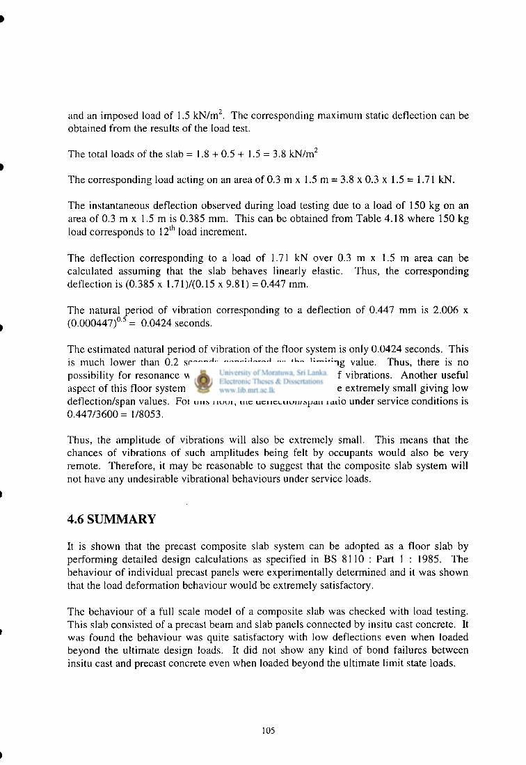
4. The precast beam in the composite slab system should be designed as a flanged beam for superimposed dead and imposed loads. This means, it is desirable to have a sufficient insitu cast flange width for the precast beam. The shape of the precast slab panels adopted to fulfill this requirement is shown in Figure 4.1 since this insitu cast concrete is laid on the precast slab panels.
5. The following points should be noted about the flange width of the beam with respect to the shape of the slab panel. The spans used for the precast beams can vary from 2.5 m to 3.5 m when used in residential buildings as explained in Section 5.2. The corresponding maximum flange widths for simply supported beams vary from 625 mm to 825 mm for a beam of width 125 mm (BS 8110/1, Cl 3.4.1.5). For a tapered length of 300 mm used in precast panels as shown in Figure 4.1, a width of 645 mm can be obtained for the flange of the beam when the precast panels are supported on a beam of width 125 mm. The precast panels should be provided with a bearing width of 40 mm. Thus, in order to determine the flange width to be used for the design calculations, the effective flange width can be calculated as for Cl 3.4.1.5 of BS 8110 : Part 1 : 1985. This should be compared with the actual flange width of 645 mm and the lesser value should be adopted. The decision to limit the flange width to 645 mm is an important one since the use of excessive tapered portions in one way precast slab panels may not be desirable with respect to carrying construction loads.
82

6. The use of the shape given in Figure 4.1 for precast slab panels also allows the placement of transverse reinforcement in the flange of the beam as given in Table 3.27 of BS 8110 : Part 1 : 1985.
7. It should be noted that the minimum thickness of the precast panel is limited to 40 mm. This is required to ensure sufficient capacity in resisting shear forces during construction.
8. In the middle portion of the precast slab panel, the width at the top was limited to 250 mm in order to provide connectivity between two adjacent precast panels by using insitu cast concrete.
9. For the precast slab panels, there was no intention to make them continuous over the precast beams. In Cl 3.6.2 of BS 8110 : Part 1 : 1985, it is proposed that when slabs need not be made continuous, it is possible to curtail the top reinforcement at a distance of 0.15 of the span from the face of the support where top reinforcement will act only to prevent cracks at the top surface. The use of a tapered length of 300 mm in the slab panels will ensure that only a distance of 235 mm (300 - 40 - 25) will be available for the transverse reinforcement from the face of the beam. This length gives approximately 0.15 times the span (235/1500 = 0.1566).
10. The precast beam size selected was 200 mm in depth and 125 mm in width. The depth depends on the need for supporting the construction loads and controlling the deflection at service. The width required is just sufficient to provide a bearing width of 40 mm for each precast slab panel as specified in Cl 5.2.3.2 of BS 8110 : Part 1 : 1985. This gives a clearance of 45 mm in between the precast slab panels as shown in Figure 4.2.
4.2.1 Design of precast slab panels for construction and imposed loads
Precast slab panels selected with dimensions shown in Figure 4.1 should be designed for two different load cases.
1. Loads acting during construction.
2. Dead and imposed loads acting during service.
The loads acting during construction consists of the weight of workmen who would be walking on the panel. For this, a concentrated load of 0.9 kN acting at the centre of a panel was considered as explained in Section 4.2. During construction, load sharing between adjacent panels is not available. Thus, each panel should be designed for the
83

total load acting on it. In order to obtain the design shear force, this concentrated load should be located at the ends of the precast panels.
When the precast panels are used to form a composite slab, it can be subjected either to uniformly distributed loads or concentrated loads. A uniformly distributed load of 1.5 kN/m 2 was considered as specified in BS 6399 : Part 1 : 1984 for self contained dwelling units. It is stated by Dias et al. (1991) that an imposed load of 1.5 kN/m 2 is often used by practicing engineers in Sri Lanka for dwelling units.
Since this composite slab system consists of individual precast panels connected by insitu concrete, the behaviour of a panel subjected to a concentrated load of 1.4 kN is also important since excessive deflection of an individual panel due to a concentrated load may not be desirable. For these concentrated loads, there can be load sharing to a certain degree. However, it is difficult to predict the extent of load sharing until a load test is carried out to determine the true load sharing characteristics of a slab.
The design calculations performed for the precast slabs are given in Appendix A.l. The following can be summarised from these calculations:
1. The area of reinforcement required in the precast slab panels can be determined to satisfy flexural requirements at ultimate limit state in the longitudinal direction. In the transverse direction, the area of reinforcement required can be determined on the basis of minimum reinforcement required for crack controlling. The guidelines on the maximum clear distance between bars is also checked.
2. The shear carrying capacity of a panel should be evaluated at ultimate limit state for both construction loads and imposed loads. During construction, the shear capacity of a precast panel close to the support can be governing the design since the effective depth is reduced considerably due to the shape of the precast panel as shown in Figure 4.1. Once the insitu concrete hardens, a total depth of 75 mm will be effective at the supports.
3. The deflection should satisfy allowable span/effective depth ratios under service load conditions.
It can be seen from design calculations given in Appendix A.l. for precast slab panels that the following reinforcement areas are required in the longitudinal direction.
1. The longitudinal reinforcement area required to support construction loads is 77.30 mm of mild steel as given in Section A. 1.3.
2. The longitudinal reinforcement area required to support a uniformly distributed load of 1.5 kN/m 2 is 46.2 mm of mild steel as given in Section A. 1.1.
84

3. If load sharing is ignored, the reinforcement area required to support a point load of 1.4 kN acting at the centre of a panel is 116 mm 2 as given in Section A. 1.2.
Since there could be load sharing to a certain extent, an area of 84.9 mm 2 was selected which comprise of three 6 mm diameter mild steel bars. It was intended to verify the adequacy of this amount of reinforcement with the establishment of load sharing characteristics.
4 .2 .2 . D e s i g n o f p r e c a s t b e a m s f o r c o n s t r u c t i o n l oads a n d i m p o s e d l o a d s
The composite slab system consists of precast beams and precast slabs connected by insitu cast concrete. The composite slab system is designed for a superimposed dead load of 0.5 kN/m representing a 20 mm cement rendering and an imposed load of 1.5 kN/m .
In the design of composite system, only the reinforced concrete flange beam needs to be designed since the precast slab panels have already been designed. For the structural design of the beam, a flanged beam of the shape given in Figure 4.2 was used. The precast slab panels supported on the precast beam were ignored since those may not be resting against each other to form a continuous slab. Thus, those would not form a compression flange for the beam.
It was shown in Appendix A.2 that the actual depth to the neutral axis would only be about 10.95 mm and hence the compression zone will be within the depth of the flange. Thus, the design can be carried out as for a flanged beam having the neutral axis within the flange using BS 8110: Part 1 : 1985.
The precast reinforced concrete beam should also be designed for construction loads. The construction loads consist of lifting stresses and the loads that act before the composite action is effective. During handling, the beam can be lifted in one of the ways shown in Figure 4.3. It is considered that the beam would be lifted at the ends which will give a maximum sagging bending moment at the centre. Sufficient reinforcement should be provided to resist the flexural moments that would arise for either case.
During construction, precast slabs will be placed on the precast beam which is simply supported. When insitu concrete is placed to form the composite system, few workmen can be expected on the slab. However, it is difficult to predict the number of workers exactly, but it could be suggested that the number should be limited. Since it is absolutely necessary to prevent failures during construction and also to prevent excessive deflections occurring in the precast beam, the following strategy wav adopted:
1. The precast beam was designed at ultimate limit state for the weight of precast slabs, insitu concrete and the weight of three workmen assumed at 0.6 kN per person. The workmen may be at the centre of the beam. The relevant calculations are given in Appendix A.3.
85

2. During construction, support the precast beams with a prop at the centre so that any deflection due to loads can be minimised. This will reduce the bending moment on the precast beams considerably and hence the chances of failure occurring will be minimised. It should be noted that it would not be necessary to design the precast beam as one with two spans continuous over a central support since a temporary prop placed on existing ground (hard earth) would not be rigid enough to induce significant hogging moments at the prop.
4.2.3. Reinforcement details for precast slabs, beams and composite system
On the basis of the design calculations presented in Appendix A, the reinforcement arrangements given in Figure 4.4 to 4.6 were selected. In the composite slab, additional reinforcement was provided within insitu cast concrete as shown in Figure 4.6 to prevent cracks due to shrinkage and early thermal stresses and, also to provide certain degree of continuity to the precast slab panels. If continuity reinforcements are required in slabs to meet robustness requirements, Cl 5.1.8 of BS 8110 : Part 1 : 1985 allows such reinforcement to be provided between two slab panels, which can be embedded in the insitu cast concrete.
4.3 E X P E R I M E N T A L P R O G R A M M E F O R C O M P O S I T E SLABS
In the composite precast reinforced concrete beam slab system, precast slab panels and precast beams are assembled to form a slab and the structural continuity is provided by using insitu cast concrete. Therefore, it is absolutely necessary to ensure that the composite system can resist loads up to ultimate loads without bond failures between precast and insitu cast concrete. It is also important to ensure that the composite slab can behave satisfactorily with respect to serviceability limit state of cracking and deflections. If satisfactory behaviour is observed for a prototype slab which has been designed for BS 8110: Part 1 : 1985 guidelines, it would be possible to use those guidelines for the design of similar composite slabs having different spans and also supporting imposed loads of different magnitudes.
In order to fulfill the above objectives, a detailed experimental programme was carried out. The details are as follows:
1. The individual precast floor panels should be able to support the construction loads and the loads at service when supported at the ends. For this, load testing was carried out on individual precast slab panels.
2. When the precast slab panels are connected by using insitu cast concrete, there should be a certain amount of load sharing and also panels should not separate
86

from each other due to maximum loads imposed on them. This is important to ensure that the soffit plaster will not develop any cracks. Thus, the load sharing characteristics of precast panels interconnected with insitu concrete should be determined. For this, load testing was carried out on precast slab panels connected with insitu cast concrete.
3. When the composite floor system is completed, it is important to ensure that this system can carry the superimposed dead loads and imposed loads acting on it. For this purpose, a full scale load test was performed on the slab.
4. Since screed concrete can be used for finishes and also to contribute to better load distribution between the precast slabs, a comparison is made between floors with a screed and without a screed.
4 . 3 . 1 T e s t i n g o f i n d i v i d u a l p r e c a s t pane l s
The precast panels should be able to carry the design loads that will act during construction and at service. Thus, load testing of few panels to verify the actual behaviour is useful.
4 .3 .1 .1 Casting of precast panels
Slab panels were precast using reusable moulds. These mould were made in such a way that the moulds could be removed about 2 hours after the casting of concrete. The concrete mix was 1:2:3:1 of cement, sand, 20 mm aggregates and 8 mm chips. A reasonably well graded aggregate mix was obtained by mixing 8 mm chips with 20 mm nominal size aggregates. Hand mixing was used for mixing of concrete to simulate typical site conditions prevailing at small construction sites. Six concrete cubes were cast from the above mix and were tested at ages of 7 and 28 days. The strengths obtained were given in Table 4.1. This mild steel used had an average yield stress of 315 N/mm 2 .
Table 4.1: Average compressive strengths of concrete used for casting precast panels
Average 7 day compressive strength (N/mm 2)
Average 28 day compressive strength
(N/mm 2) 7.56 15
These cubes have given strengths lower than expected, but it was decided to use these panels for load testing purposes since a low strength for concrete would indicate a more critical case that might arise in practice.
87

4.3.1.2 Testing of individual precast panels
The testing of individual precast panels was carried out using the arrangement shown in Figure 4.7 for three panels. This loading creates a constant bending moment in the mid region due to imposed loads between the two point loads. Thus, the precast slab is likely to fail at the weakest point in the mid region. The results are given in Table 4.2. The load deformation curves for panels are given in Charts 4.1 to 4.3.
Table 4.2: Load deformation results for precast slab panels
Load (kg) Deflection of panel No 1 (mm)
Deflection of panel No 2 (mm)
Deflection of panel No 3 (mm)
0 0.00 0.00 0.00 40 0.04 0.08 0.00 80 0.14 0.19 0.12 120 0.28 0.27 0.18 160 0.50 0.37 0.26 200 0.66 0.62 0.32 240 0.85 0.80 0.41 280 1.07 1.23 0.52 320 1.42 1.60 0.68 360 1.95 2.22 0.99 400 2.84 3.24 1.37 440 3.50 3.97 2.12 480 *
4.67 5.23 2.84* 520 5.21 5.93 3.64 560 6.05 6.80 4.24 600 10.77" 7.62* 4.88 640 - 8.16 5.54 680 - 8.92 5.98 700 - failure -720 - 6 .53"
* load at first crack of 0.3 mm in width failure load
The design bending moment due to a concentrated load of 1.4 kN acting at the centre of a panel is 0.802 kNm as shown in Section A. 1.4. When the panel is loaded with two point loading, this moment is caused by a total load of 0.290 Tonnes as described in Section A.4.1.
It can be seen from Table 4.2 that the maximum deflection corresponding to a load of 0.320 Tonnes (> 0.29 Tonnes) obtained from panel testing is 1.60 mm, thus less than span/250 (or 20 mm whichever is less) specified in Cl 3.4.6.3 of BS 8110 : Part 1 :1985
88

(1410/250 = 5.64 mm). Thus, the deflection requirement can be satisfied even when ultimate loads are acting on the panel.
4.3.1.3 Cracks at service conditions
The minimum load that caused a crack of width 0.3 mm in these three slabs was 0.48 Tonnes. The location of the crack was close to the mid span. This corresponds to a bending moment of 1.23 kNm (see Section A.4.2). This is much higher than the maximum service bending moment caused by a load of 1.4 kN at the centre which can be calculated as 0.667 x 1.4 x 1.46/4 + 0.523 x 1.462/8 = 0.480 kNm. It should be noted that an individual panel would carry a maximum of 66.67% of the load acting on it due to load sharing as shown in Section 4.4.1. The dead load of the precast panel is 0.523 kN/m as given in Appendix A.4.1. The span is 1.46 m.
4.3.1.4 Ultimate load carrying capacity
The minimum ultimate load of the three panels tested was 0.60 Tonnes. This load gives rise to a ultimate bending moment of 1.513 kNm as described in Section A.4.2. The design ultimate moment due to self weight and a load of 1.4 kN at the centre is 0.802 kNm with load sharing as shown in Section A. 1.4. Thus the actual strength exceeds the required ultimate strength by a considerable margin.
4.3.2 Testing of precast slabs for load sharing
Although it is possible for a slab panel to carry the design service loads without significant deflection, it is important to ensure that precast slabs behave as one unit when joined together with insitu concrete. For this purpose, the load sharing characteristics of composite slabs were determined.
4.3.2.1. Casting of composite slabs
In order to determine the load sharing characteristics, five precast panels were used to form a slab of thickness 75 mm as shown in Figure 4.8. In order to prevent early thermal cracking and shrinkage cracking in insitu cast concrete, the reinforcement shown in Figure 4.9 was used. It was found that the use of 20 mm crushed aggregates was not possible for the insitu cast concrete since at some places the thickness of insitu concrete was limited to 20 mm. Even when chips were used as coarse aggregates, extremely workable mix with high cement content was required to provide a satisfactory finish for insitu cast concrete. Thus, the mix used for insitu concrete was 1.5:2.5:3.5 of cement, sand and chips. The strengths obtained for insitu concrete of abo v e mix proportions are given in Table 4.3.
89

Table 4.3: Concrete cube test results for the mix of 1.5:2.5:3.5 (cement, sand, 8 mm chips)
Average 7 day strength (N/mm 2)
Average 28 day strength (N/mm 2)
13.75 16.7
Two slabs consisting of five panels were cast by supporting the precast slab panels on cement stabilised soil block walls. One of them was provided with a screed concrete of 1:3:3 cement, sand and 8 mm chips to determine the effects of a strong screed on load sharing characteristics. It should be noted that the cost of this screed concrete is approximately the same as 1:6 cement sand mortar, since the cost of 8 mm chips is approximately same as the cost of sand.
Three 150 mm cubes made with this mix have given an average strength of 7.0 N/mm 2 at 28 days. Such screeds can be used instead of 1:4 or 1:5 cement sand for rendering purposes especially when tiles are used as the decorative floor finish. It is also possible to give a smooth floor finish for such screeds with cement float as usually done with cement sand mortar renderings.
4.3.2.2 Load testing of composite slabs without screed
The load testing was carried out at an age of about one month after casting. In load testing, it is important to consider the effects of movements caused by environmental temperature changes which can alter the thermal gradient across the depth of construction. Thus, the slab formed by connecting five precast panels by insitu concrete was left for 24 hours after fixing the dial gauges. Dial gauge readings were recorded from 0800 hours until 1800 hours which was the duration in which the load test readings were recorded. The temperature readings and the variation of dial gauge readings are given in Table 4.4, where the dial gauges were mounted as shown in Figure 4.8.
The values given in Table 4.4 indicates that there is a possibility for a change of about 0.01 mm in the dial gauge reading due to a temperature change of 2.5 °C. Since, the temperature of the laboratory remained within 28° C and 30°C during the load testing, changes to dial gauge readings due to such temperature variation were ignored.
Table 4.4: Variation of dial gauge readings with changes in surrounding temperature
Temperature Dial gauge A (mm) Dial gauge B (mm) Dial gauge C (mm) 28.0 30.55 10.88 5.86 28.5 30.55 10.88 5.86 29.0 30.55 10.88 5.87 30.0 30.56 10.88 5.87 30.5 30.56 10.89 5.87
90

In order to determine the load sharing characteristics, a point load of 1.6 x 1.4 kN = 2.24 kN was applied at the central panel (location C as shown in Figure 4.8) with 25 kg load increments. Five minutes were allowed to lapse between two consecutive load increments. The dial gauges were fixed at locations A, B and C as shown in Figure 4.8. The load deflection readings obtained for this load test are given in Table 4.5. The corresponding load deflection curves for each slab panel is given in Chart 4.4.
Table 4.5: Load sharing in a precast slab connected by insitu concrete when an interior panel was loaded (without a screed)
Load (kg)
Deflection (mm) Load (kg) Dial gauge A Dial gauge B Dial gauge C Load (kg)
loading unloading loading unloading loading unloading 0 0.000 0.000 0.000 0.000 0.000 0.000
25 0.000 0.005 0.005 0.005 0.005 0.005 50 0.025 0.010 0.010 0.010 0.010 0.010 75 0.005 0.0125 0.0125 0.0125 0.015 0.015 100 0.0075 0.015 0.0175 0.020 0.020 0.020 125 0.010 0.020 0.020 0.0225 0.025 0.025 150 0.015 0.0225 0.0275 0.030 0.030 0.0325 175 0.020 0.025 0.0325 0.0325 0.035 0.035 200 0.020 0.0275 0.0375 0.0375 0.040 0.040 225 0.0225 0.030 0.040 0.045 0.045 0.0475 250 0.030 0.030 0.045 0.045 0.0525 0.0525
It can be seen from the deflections that there was a significant load transfer to the adjacent panels. The ratio of load carried by each panel can be calculated using Equation 2.6 which can be rearranged as given below to give the percentage of load carried by a panel.
W S Percentage of load carried =^—x 100% = x 100% (4.1)
where W r = the load on r l h beam 8 r = the deflection of the r t h beam ZW r = sum of the corresponding beam loads Z5 r = the sum of corresponding beam deflections
For example, the maximum deflections given in Table 4.5 are 0.03 mm, 0.045 mm and 0.0525 mm for dial gauge locations A, B and C, respectively. If a total of five panels share the loads, then the load carried by the panel at the centre is {0.0525 / (0.0525 + 2 x 0.045 + 2 x 0.03)} x 100% = 25.9%. The corresponding results are given in Table 4.6 for the panels without screed.
91

Table 4.6: Load sharing characteristics of precast slab panels without a screed where five panels participate in load sharing
Panel % load taken by a panel Panel A 14.8% Panel B 22.2% Panel C 25.9%
It may be reasonable to suggest that only 30% of the concentrated load is taken by an interior panel when the concentrated load acts on it. This is quite significant for design purposes since only 30% of the concentrated loads acting on an individual slab should be used to calculate the reinforcement requirement. In this case, a total of five precast panels have participated in the load sharing.
However, the guidelines given in Cl 5.2.2.2 of BS 8110 : Part 1 : 1985 can be more restrictive than this. For concentrated loads acting on slabs, the width of the slab assumed to contribute to the support of concentrated loads should not exceed the width of three precast units and joints plus the width of the loaded area. This means that it is safer to assume that only three panels participate in load sharing.
There is an additional restriction in the same clause which states that the width of the slab supporting the concentrated load shall not extend more than a quarter of the span on either side of the loaded area. This width is (1500 - 40) x 0.25 = 365 mm on each side for the slab under consideration. With this restriction also, it may be reasonable to assume that three panels participate in load sharing. In this case, the total width of 900 mm given by three precast panels consist of a width of 170 mm for the loaded area.
If these guidelines are considered, it may be appropriate to consider that only three panels participate in resisting the concentrated loads. Thus, the load sharing characteristics can be calculated considering deflections for the central panel and the two panels on either side. For this purpose, the load deformation data given in Table 4.5 can be used. The load sharing values under these conditions are given in Table 4.7.
Table 4.7: Load sharing characteristics of precast slab panels without a screed where only three panels participate in load sharing
Panel % load taken by a panel Panel B 31.5% Panel C 37.0%
It may be reasonable to suggest that only 40% of the concentrated load is taken by an interior panel when a concentrated load acts on it with the guidelines given in Cl 5.2.2.2 of BS 8110 : Part 1 : 1985 being effective. ygC. v .

There is a possibility for the concentrated load to act on an edge panel where the precast panels only on one side will participate in load sharing. In order to determine the load sharing characteristics under such circumstances, a point load of 1.6 x 1.4 kN = 2.24 kN was applied on an edge panel (location A as shown in Figure 4.8) with 25 kg load increments. The dial gauges were fixed at locations A, B and C as shown in Figure 4.8. The load deflection readings obtained for this load test are given in Table 4.8. The corresponding load deflection curves for each slab panel is given in Chart 4.5.
Table 4.8: Load sharing in a precast slab connected by insitu concrete when an edge panel was loaded (without a screed)
Load (kg)
Deflection (mm) Load (kg) Dial gauge A Dial gauge B Dial gauge C Load (kg)
loading unloading loading unloading loading unloading 0 0.000 0.0125 0.000 0.000 0.000 0.000
25 0.010 0.0175 0.005 0.0125 0.005 0.000 50 0.020 0.0275 0.010 0.015 0.0075 0.0025 75 0.030 0.040 0.0175 0.020 0.010 0.010 100 0.0425 0.050 0.025 0.0275 0.015 0.010 125 0.055 0.060 0.0325 0.0475 0.020 0.020 150 0.065 0.070 0.0375 0.0475 0.0225 0.025 175 0.075 0.085 0.045 0.055 0.0275 0.030 200 0.090 0.095 0.055 0.060 0.030 0.035 225 0.100 0.105 0.060 0.0625 0.035 0.035 250 0.110 0.11 0.065 0.065 0.040 0.040
The load sharing characteristics calculated by considering that three panels participate in load sharing are given in Table 4.9. The load sharing characteristics calculated by considering that only two panels participate in load sharing are given in Table 4.10. In this case, the number of panels participating in load sharing is in agreement with Cl 5.2.2.2 ofBS 8110: Part 1 : 1985.
Table 4.9: Load sharing characteristics with an edge slab panel loaded where three panels participate in load sharing (slab without a screed)
Panel % load taken by a panel Panel A 51.1% Panel B 30.2% Panel C 18.7%
93

•
Table 4.10: Load sharing characteristics with an edge slab panel loaded where only two panels participating in load sharing (slab without a screed)
Panel % load taken by a panel Panel A 62.8% Panel B 37.2%
It may be reasonable to suggest that only 2/3 or 66.67% of the concentrated load is taken by an edge panel when a concentrated load acts on it with the guidelines given in Cl 5.2.2.2 of BS 8110 : Part 1 : 1985 being effective.
4.3.2.3 Load testing of composite slabs with screed
The load carried by each slab panel can be calculated as shown in Section 4.3.2.2 for a slab with a screed. The screed used was 1:3:3 cement sand and 8 mm chips since it is stronger and less liable to develop shrinkage cracking that is generally associated with 1:5
^ cement sand mortar. This screed could either be used as the base for tiling or it could be given a smooth finish with cement float.
In order to determine the load sharing characteristics, a point load of 1.6 x 1.4 kN = 2.24 kN was applied at the central panel (location C) as shown in Figure 4.8 with 25 kg load increments. The dial gauges were fixed at locations A, B and C as shown in Figure 4.8. The load deformation readings obtained for this load test are given in Table 4.11. The corresponding load deformation curves for each slab panel is given in Chart 4.6. The panels with the screed has given lower deflection than the panels without a screed which may be due to increase in stiffness as explained in Section 2.3.6.
Table 4.11: Load sharing in a precast slab connected by insitu concrete when an interior panel was loaded (with a screed)
* Load (kg)
Deflection (mm) Load (kg) Dial gauge A Dial gauge B Dial gauge C Load (kg)
loading unloading loading unloading loading unloading 0 0.000 0.000 0.000 0.000 0.000 0.000
25 0.000 0.000 0.000 0.000 0.000 0.000 50 0.000 0.025 0.005 0.005 0.005 0.005 75 0.000 0.005 0.005 0.0075 0.005 0.005 100 0.0025 0.005 0.010 0.010 0.010 0.010 125 0.0025 0.0075 0.0125 0.0125 0.015 0.015 150 0.0025 0.010 0.0150 0.015 0.015 0.015 175 0.005 0.0125 0.020 0.020 0.0175 0.020 200 0.010 0.015 0.0225 0.025 0.020 0.025 225 0.010 0.015 0.025 0.025 0.025 0.025 250 0.015 0.015 0.030 0.030 0.035 0.035
94

The corresponding load sharing characteristics with five panels participating in load sharing are given in Table 4.12. The load sharing characteristics with only three panels participating in load sharing are given in Table 4.13 which is in compliance with that specified in Cl 5.2.2.2 of BS 8110 : Part 1 : 1985.
Table 4.12: Load sharing characteristics of precast slab panels with a screed when an interior panel was loaded where five panels participate in load sharing
Panel % load taken by a panel Panel A 12.0% Panel B 24.0% Panel C 28.0%
It may be reasonable to suggest that only 30% of the concentrated load is taken by an interior panel when the concentrated load acts on it. In this case, a total of five precast panels have participated in the load sharing.
Table 4.13: Load sharing characteristics of precast slab panels with a screed when an interior panel was loaded where only three panels participate in load sharing
Panel % load taken by a panel Panel B 31.6% Panel C 36.8%
It may be reasonable to suggest that only 40% of the concentrated load is taken by an interior panel when a concentrated load acts on it with the guidelines given in Cl 5.2.2.2 of BS 8110 : Part 1 : 1985 being effective.
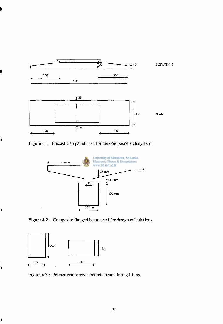
When a concentrated load acts on an edge panel, the precast panels only on one side will participate in load sharing. In order to determine the load sharing characteristics under such circumstances, a point load of 1.6 x 1.4 kN = 2.24 kN was applied at the edge panel (location A as shown in Figure 4.8) with 25 kg load increments. The dial gauges were fixed at locations A, B and C as shown in Figure 4.8. The load deformation readings obtained for this load test are given in Table 4.14. The corresponding load deformation curves for each slab panel is given in Chart 4.7.
95

Table 4.14: Load sharing in a precast slab connected by insitu concrete when an edge panel was loaded (with a screed)
Load (kg)
Deflection (mm) Load (kg) Dial gauge A Dial gauge B Dial gauge C Load (kg)
loading unloading loading unloading loading unloading 0 0.000 0,005 0.000 0.0025 0.000 0.000
25 0.005 0.010 0.000 0.005 0.000 0.0025 50 0.0125 0.015 0.005 0.010 0.005 0.005 75 0.020 0.0225 0.010 0.015 0.075 0.0075 100 0.025 0.0275 0.0125 0.0175 0.010 0.010 125 0.030 0.035 0.0175 0.025 0.010 0.0125 150 0.0375 0.040 0.020 0.0275 0.0125 0.015 175 0.045 0.0475 0.025 0.030 0.0175 0.0175 200 0.0525 0.0525 0.0275 0.035 0.0175 0.020 225 0.0575 0.0575 0.0325 0.0375 0.020 0.0225 250 0.0625 0.0625 0.040 0.040 0.0225 0.0225
The load sharing characteristics calculated by considering that three panels participate in load sharing is given in Table 4.15. The load sharing characteristics calculated by considering that only two panels participate in load sharing is given in Table 4.16, which is in agreement with Cl 5.2.2.2 of BS 8110 : Part 1 : 1985.
Table 4.15: Load sharing characteristics with an edge slab panel loaded where three panels participate in load sharing (slab with a screed)
Panel % load taken by a panel Panel A 50.0% Panel B 32.0% Panel C 18.0%
Table 4.16: Load sharing characteristics with an edge slab panel loaded where only two panels participate in load sharing (slab with a screed)
Panel % load taken by a panel Panel A 60.9% Panel B 39.1%
It may be reasonable to suggest that only 2/3 or 66.67% of the concentrated load is taken by an edge panel when a concentrated load acts on it with the guidelines given in Cl 5.2.2.2 of BS 8110 : Part 1 : 1985 being effective.
96

In practice, it is unlikely to specify different reinforcement details for edge panels and interior panels when only normal site supervision is available. Therefore, it may be safer to recommend that only 2/3 or 66.67% of a concentrated load would be carried by a panel when load sharing is available. This value can be used for slabs with or without a screed for both edge and interior panels.
4.3.2.4 Deflection of a precast panel with load sharing
It is necessary to show that the deflection of a panel subjected to a concentrated load is within the allowable limits when load sharing is available. It is shown in Appendix A. 1.4 that when it is assumed that only 2/3 of the load is carried by each panel, it is sufficient to use three 6 mm diameter mild steel reinforcement for precast panels which is in agreement with the reinforcement provided in the precast panels. When load sharing is available, the maximum service bending moment due to a concentrated load of 1.4 kN can be calculated as follows.
Dead load = 0.3 x 0.075x 24 = 0.54 kN/ m
Superimposed dead load = 0.5 x 0.3 = 0.15 kN/m
Service bending moment due to the concentrated load assuming that 2/3 of the imposed load is resisted by a panel
= {( 0.54 + 0.15) x 1.462/8} + {1.4 x 0.667 x 1.46/4} = 0.525 kNm
It would be possible to calculate the deflection corresponding to a bending moment of 0.525 kNm by using the results obtained for load testing of individual panels. This would be an approximate calculation since the loading is different. The corresponding load can be calculated as explained in Appendix A.4.1. The relevant calculations are given below.
0.525 = (W/2) x 0.47 + 0.523 x 1.412/8
W = 1.68 kN= 171 kg.
The maximum deflection corresponding to a load of 200 kg (>171 kg) can be obtained from Table 4.2. This value is 0.66 mm. This is much lower than the allowable deflection of span/250 = 1460/250 = 5.84 mm. It can be seen from the load deflection curves given in Charts 4.1 to 4.3 that in this load range, the load deflection behaviour is approximately linear.
4.3 .3 Load testing of composite slab system
When precast products are introduced, it is important to ensure that those can be designed using either existing or new mathematical models. In this particular instance, it would be
97

useful to determine whether the composite slab system can be designed by using the guidelines given in BS 8110 : Part 1: 1985. These guidelines could be used provided that the composite slab consisting of precast units connected by insitu concrete remains as one unit without any bond failures between insitu and precast concrete even when loaded to the ultimate limit state. If this can be established, the guidelines given in BS 8110 : Part 1 : 1985 are sufficient to design a precast composite slab system of this nature for other span lengths and any other imposed load condition. In order to determine the actual behaviour of a composite slab, a load test was carried out on a full scale slab.
4.3.3.1 Casting of composite slab
It was decided to cast a composite slab of dimensions 3.0 m x 3.6 m. In order to simulate the actual conditions, a precast beam was used at the centre. The panels were supported on cement stabilised soil block walls on either side and on the centre beam as shown in Figure 4.10 thus giving a total panel width of 3.045 m as the gap on the beam is 45 mm. A length of 3.6 m was selected for the beam since it is considered as the maximum length that can be precast and lifted to the position with ease by six people. The weight of the beam is about 180 kg. The reinforcement arrangement used for the beam was as given in Figure 4.5. The 1:2:4 cement, sand and 20 mm aggregate concrete, which was used for the beam, had a cube strength of 25 N/mm 2 at an age of 28 days.
The slab construction involved the following steps:
1. Construction of walls that supported the precast slabs as shown in Figure 4.10.
2. Placing of the precast beam on walls; for this four people were involved. The time taken was about half an hour.
3. Placing of precast slabs on the precast beam and walls on either side to form the slab; for this three people were involved and the time taken was about one hour.
4. Placing of crack controlling reinforcement as shown in Figure 4.6 and then placing of insitu concrete of 1.5:2.5:3.5 cement, sand and 8 mm chips to connect the precast components. For this, two people were involved and the time taken was about 4 hours.
Curing was started 24 hours after the casting of the slab and was continued for 14 days. The strength of concrete used for insitu casting is given in Table 4.3.
4.3.3.2 Effects of temperature variation
In order to determine the effects of temperature variation on the dial gauge readings of the composite slab, readings of three dial gauges fixed as shown in Figure 4.10 were monitored. The readings are given in Table 4.17 . Since the laboratory used for the full scale model testing was well sheltered, only small temperature variations were recorded.
98

It could be seen from Table 4.17 that the dial gauge readings were not affected by the small variation of temperature recorded inside the laboratory.
Table 4.17: Effects of temperature variation on the dial gauges used for the load testing of composite slab
Temperature °C Dial gauge No 1 (mm)
Dial gauge No 2 (mm)
Dial gauge No 3 (mm)
27.5° 45.51 8.87 5.41 28.0° 45.51 8.87 5.41 28.5° 45.51 8.87 5.41 29.0° 45.51 8.87 5.41
4.3.3.3 Load testing of composite slab
Twenty eight days after casting of insitu concrete, a load test was carried out. There was an important difference between a normal load test that would be carried out for structural appraisal of an existing slab and this particular case. In a normal load test, the attention should be focused on assessing whether the slab could carry the dead and imposed loads with a sufficient margin of safety. In this particular case, the attention was focused on the behaviour of the slab, specially the chances for disintegration of insitu concrete from precast concrete. Therefore, the ultimate load intended to apply was not -1.25 x imposed load as recommended in Cl 9.5.2 of BS 8110 : Part 2 : 1985, but 0.4 x dead load + 1.4 x superimposed dead load + 1.6 x imposed load.
The corresponding loads can be calculated as follows:
1. Dead load of the slab = 0.075 x 24 = 1.8 kN/m 2
2. Superimposed dead load = 0.5 kN/m 2
3. Imposed load =1.5 kN/m 2
Total load required = 0.4 x 1.8 + 1.4 x 0.5 + 1.6 x 1.5 = 3.82 kN/m 2
The load required over one panel of 0.3 m x 1.5 m = 0.3 x 1.5 x 3.82 = 1.719 kN
For the load testing, gunny bags were filled with 25 kg of dry sand and arranged in such a way as one bag to be spread over an area of approximately 300 mm x 500 mm. The loading sequence of slabs is given in Figure 4.11. Thus, when the whole slab is covered by one layer of sand bags, it involved six loading steps. The equivalent load was 1.635 kN/m 2 (0.025 x 9.81/(0.5 x 0.3)). At each load increment, deflections of dial gauges placed at locations shown in Figure 4.10 were recorded.
99

When the second layer of sand bags were completed, the load was 3.27 kN/m 2 (1.635 x 2). This is more than 1.25 times the addition of design live load of 1.5 kN/m 2 and an allowance of 0.5 kN/m 2 for finishes which is (0.5 + 1.5) x 1.25 = 2.5 kN/m 2. Thus, the applied load is 30.8% more than the required.
In order to determine the performance of the slab at ultimate limit state, a load of 3.82 kN/m 2 should be applied.
This load is equivalent to 175 kg per panel of area 0.3 m x 1.5 m. For the load test, a total of 9 bags, each weighing 25 kg, were applied over an area of 0.3 m x 1.5 m. The corresponding load is 225 kg, which is more than the estimated ultimate load by 28.5%.
Table 4.18: Deflections in the loading cycle No 1 of full scale load testing
Load increment
Deflection (mm) Load increment Dial gauge 1 Dial gauge 2 Dial gauge 3
Load increment
loading unloading loading unloading loading unloading 0 0.000 0.015 0.000 0.085 0.000 0.080 1 0.045 0.106 0.045 0.145 0.035 0.110 2 0.070 0.136 0.085 0.200 0.080 0.165 3 0.120 0.186 0.125 0.240 0.100 0.180 4 0.135 0.206 0.155 0.275 0.145 0.230 5 0.160 0.236 0.170 0.295 0.150 0.240 6 0.165 0.246 0.180 0.315 0.175 0.265 7 0.210 0.356 0.235 0.370 0.200 0.295 8 0.235 0.386 0.285 0.420 0.250 0.345 9 0.320 0.426 0.315 0.460 0.260 0.365 10 0.320 0.446 0.355 0.495 0.305 0.415 11 0.360 0.466 0.370 0.515 0.315 0.420 12 0.360 0.476 0.385 0.530 0.345 0.450 13 0.420 0.531 0.450 0.585 0.375 0.475 14 0.440 0.553 0.510 0.635 0.435 0.520 15 0.510 0.585 0.560 0.665 0.460 0.535 16 0.530 0.590 0.630 0.700 0.535 0.580 17 0.580 0.590 0.670 0.715 0.555 0.585 18 0.585 0.590 0.705 0.720 0.605 0.610
The load test was carried out in the following sequence as stated in Cl 9.5.2 of BS 8110 : Part 2 : 1985:
Loading cycle No 1: Load the slab to ultimate load given by three layers of sand bags. At the end of each load increment, an interval of five minutes was allowed before recording
100

the readings. There were 18 load increments for a loading operation. Then the slab was unloaded gradually following the loading sequence in the reverse order.
Loading cycle No 2: Repeat the load test as given in loading cycle No 1 with a lapse of at least one hour from loading cycle No 1.
Loading cycle No 3: Repeat the load test as above, but sustain the load for 24 hours before unloading.
The results of load tests are presented in Table 4.18 - 4.20. Those are presented graphically in Charts 4.8 - 4.10.
Table 4.19: Deflections in the loading cycle No 2 of full scale load testing
Load increment
Deflection (mm) Load increment Dial gauge 1 Dial gauge 2 Dial g auge 3
Load increment
loading unloading loading unloading loading unloading 0 0.000 0.015 0.000 0.040 0.000 0.020 1 0.045 0.065 0.050 0.100 0.025 0.055 2 0.070 0.095 0.095 0.155 0.075 0.105 3 0.120 0.150 0.135 0.195 0.090 0.125 4 0.135 0.230 0.165 0.235 0.130 0.175 5 0.160 0.250 0.185 0.255 0.140 0.185 6 0.170 0.250 0.205 0.270 0.165 0.215 7 0.250 0.315 0.255 0.325 0.195 0.245 8 0.260 0.345 0.305 0.385 0.245 0.295 9 0.310 0.390 0.345 0.425 0.265 0.315 10 0.340 0.405 0.385 0.455 0.315 0.365 11 0.350 0.430 0.405 0.475 0.320 0.370 12 0.350 0.445 0.420 0.495 0.350 0.405 13 0.435 0.490 0.480 0.550 0.385 0.425 14 0.470 0.515 0.535 0.600 0.435 0.475 15 0.510 0.555 0.580 0.635 0.455 0.490 16 0.510 0.570 0.620 0.665 0.505 0.535 17 0.570 0.570 0.650 0.685 0.515 0.54 18 0.570 0.570 0.670 0.695 0.550 0.561
The maximum deflection recorded at the centre of a beam was about 0.72 mm as indicated in Table 4.18. The allowable deflection is given as span/250 in BS 8110 : Part 1 : 1985. In this case, the allowable deflection is 3600/250 = 14.4 mm at the centre of the precast beam. No cracks were observed during the load test and it is unlikely for any cracks to occur with deflections as low as 0.72 mm.
101

In this load test, the recovery was very good. The percentages of recovery were not calculated since the total deflections observed were of quite low magnitude than the allowable values as stated in Cl 9.5.4 of BS 8110 : Part 2 : 1985.
I The deflection Vs load increment Charts 4.8 to 4.10 can be used to obtain the load deformation behaviour as well. For this only four deflection readings can be used, which are at the load increments of 0, 6, 12 and 18. These correspond to the application of each layer of sand bags covering the whole slab. It can be seen that the load deformation behaviour given by above four points are approximately linear up to the ultimate loads.
Table 4.20: Deflections in the loading cycle No 3 of full scale load testing where the loads were sustained for 24 hours
Load increment
Deflection (mm) Load increment Dial gauge 1 Dial gauge 2 Dial gauge 3
Load increment
loading unloading loading unloading loading unloading 0 0.000 0.000 0.000 0.030 0.000 0.010 1 0.045 0.055 0.050 0.090 0.030 0.045 2 0.075 0.085 0.100 0.150 0.075 0.095 3 0.125 0.175 0.140 0.190 0.090 0.110 4 0.135 0.195 0.175 0.230 0.140 0.165 5 0.200 0.215 0.190 0.250 0.150 0.175 6 0.200 0.215 0.210 0.275 0.180 0.210 7 0.255 0.295 0.270 0.330 0.210 0.240 8 0.285 0.325 0.325 0.390 0.260 0.290 9 0.320 0.370 0.360 0.430 0.280 0.310 10 0.360 0.385 0.405 0.470 0.330 0.360 11 0.375 0.415 0.425 0.490 0.340 0.370 12 0.375 0.425 0.445 0.510 0.370 0.400 13 0.430 0.460 0.505 0.560 0.425 0.425 14 0.485 0.485 0.565 0.610 0.450 0.470 15 0.520 0.530 0.605 0.645 0.470 0.485 16 0.535 0.545 0.650 0.680 0.520 0.530 17 0.570 0.565 0.675 0.700 0.530 0.535 18 0.575 0.565 0.700 0.710 0.570 0.560
4.4 CONCLUSIONS OF LOAD TESTING
In the load testing carried out, precast panels connected with insitu concrete were used to determine the load sharing characteristics. The load testing on a full scale model composite slab was used to determine the behaviour when subjected to ultimate loads.

4.4.1 Precast slab panels
The precast slab panels should be designed for dead weight, construction loads, superimposed dead loads and imposed loads. When designing precast panels for concentrated imposed loads, the effects of load sharing can be taken into account. On the basis of results obtained, it is suggested that only about 40% of a concentrated load will be carried by an interior panel. For an edge panel, this value will be about 2/3 or 66.67% with only the adjacent panel sharing the load. Thus, 2/3 or 66.67% can be used for design purposes, which gives a conservative result for interior panels.
In was shown in Section 4.3.2.4 that the load deflection behaviour of a slab panel is almost linear for the bending moments that can be expected under service conditions. It was also shown that with a structural screed laid on precast panels, the deflection of panels can be reduced to a certain extent. This reduction in deflection was in the range of 40%. The load sharing characteristics of slabs with screed were more or less similar to the slabs without screed. Thus, it could be stated that a strong screed could contribute to improve the stiffness of precast slab panels, which are connected with insitu cast concrete as in this case.
4.4.2 Behaviour of composite slabs
The composite slab consisting of precast beams and slabs connected with insitu concrete showed an excellent behaviour even under ultimate limit state loads. Not a single crack was developed by the composite slab system even when loaded beyond the ultimate loads. There were no bond failures between insitu and precast concrete. This indicates that this composite slab system can be designed with confidence by using the guidelines and design principles given in BS 8110 : Part 1 : 1985. This will be extremely useful when the same slab system is adopted in other buildings with different magnitudes of imposed loads and also with different span lengths.
4.5 V I B R A T I O N RESPONCE OF PRECAST COMPOSITE SLAB SYSTEM
The problem of occupant induced vibrations in buildings is one of growing importance. Until recently, this problem was thought to be confined to floors of timber or light steel construction (William & Waldron, 1994). When light concrete floors are used, those can be sufficiently light and flexible to give rise to levels of vibration where the resulting motions may be of significant amplitude to cause discomfort to building occupants. In Cl 2.2.3.5 of BS 8110 : Part 1 : 1985, it is stated that discomfort or alarm to occupants due to vibrations in flexible components should be paid special attention.
Assessment of floor vibrations requires knowledge of the level of vibrations that will cause disturbance, the dynamic characteristics of the floor and the response of the floor to
103

occupant loadings. For the proposed precast beam slab system also, it was considered appropriate to check the dynamic characteristics by using a suitable method.
The dynamic characteristics of a floor is generally stated by using the natural frequency of vibration. An approach often used for one way spanning composite floors was the equivalent beam method in which a steel joist and an appropriate width of floor were used to calculate the section properties of a composite floor. The natural frequency, f0, could then be found by the formula for a simply supported beam.
where E = elastic modulus I = second moment of area of the equivalent section (transformed to a single material) m = mass per unit length 1 = the span of the slab
It was stated by William and Waldron (1994) that the equivalent beam method can underestimate the correct frequency for concrete floors by about 50%.
For the present study, a different approach was adopted since the actual deflection measurements are available as load test results. It was stated by Schuller (1990) that the natural period of vibration of a floor could be estimated by treating the uniformly loaded structure as an equivalent one degree system as in the case of an inverted pendulum. For a single degree system, the following relationships could be used to find the fundamental natural frequency.
A = the maximum static deflection caused by dead and live loads when vibrating W = the weight of the structure m = the mass of the structure k = the stiffness of the structure.
The value of constant C is generally less than 2.006 and vary between 1.6 to 2.006 with 1.87 being a recommended value for most of the floors. For the proposed slab, C = 2.006 was used since it gives a maximum value for the natural period. A natural period of vibration above 0.2 seconds can lead to resonance as described in Section 2.3.7.
The service loads on the composite slab consist of a self weight of 0.075 x 24 = 1.8 kN/m 2 (ignoring the self weight of the beam), a superimposed dead load of 0.5 kN/m 2
(4.2)
(4.3)
where
104
and an imposed load of 1.5 kN/m 2. The corresponding maximum static deflection can be obtained from the results of the load test.
The total loads of the slab = 1.8 + 0.5 + 1.5 = 3.8 kN/m 2
The corresponding load acting on an area of 0.3 m x 1.5 m = 3.8 x 0.3 x 1.5 = 1.71 kN.
The instantaneous deflection observed during load testing due to a load of 150 kg on an area of 0.3 m x 1.5 m is 0.385 mm. This can be obtained from Table 4.18 where 150 kg load corresponds to 12 t h load increment.
The deflection corresponding to a load of 1.71 kN over 0.3 m x 1.5 m area can be calculated assuming that the slab behaves linearly elastic. Thus, the corresponding deflection is (0.385 x 1.71 )/(0.15 x 9.81) = 0.447 mm.
The natural period of vibration corresponding to a deflection of 0.447 mm is 2.006 x (0.000447)° 5 = 0.0424 seconds.
The estimated natural period of vibration of the floor system is only 0.0424 seconds. This is much lower than 0.2 seconds considered as the limiting value. Thus, there is no possibility for resonance which can lead to amplification of vibrations. Another useful aspect of this floor system is that the deflections obtained are extremely small giving low deflection/span values. For this floor, the deflection/span ratio under service conditions is 0.447/3600= 1/8053.
Thus, the amplitude of vibrations will also be extremely small. This means that the chances of vibrations of such amplitudes being felt by occupants would also be very remote. Therefore, it may be reasonable to suggest that the composite slab system will not have any undesirable vibrational behaviours under service loads.
4.6 SUMMARY
It is shown that the precast composite slab system can be adopted as a floor slab by performing detailed design calculations as specified in BS 8110 : Part 1 : 1985. The behaviour of individual precast panels were experimentally determined and it was shown that the load deformation behaviour would be extremely satisfactory.
The behaviour of a full scale model of a composite slab was checked with load testing. This slab consisted of a precast beam and slab panels connected by insitu cast concrete. It was found the behaviour was quite satisfactory with low deflections even when loaded beyond the ultimate design loads. It did not show any kind of bond failures between insitu cast and precast concrete even when loaded beyond the ultimate limit state loads.
105

Thus, it could be stated that the composite precast reinforced concrete beam slab system can be designed with confidence in accordance with the guidelines given in BS 8110 : Part 1 : 1985.
Although this slab system can be considered as light weight, it will not have any undesirable vibrational characteristics since the stiffness of the composite slab system is quite high.
106
300
3 I 40
300 4 300 —t> 4 • 1500
I 2 5
300
300
ELEVATION
PLAN
Figure 4.1 Precast slab panel used for the compos i t e slab sys tem
625 mm
20 mm
125 mm 4 •
Figure 4 .2 : C o m p o s i t e f langed beam used for des ign calculat ions
200 125
125 4 •
200 4 •
Figure 4 .3 : Precast reinforced concrete beam during lifting
107

i - L
300
- L
300
< 1, ^ 1
1500
"3 Nos R6
J
Section A-A
Figure 4.4 : Reinforcement details of precast slab panels
2R6-2
1 1 1
— R6-3-100 1 2T12-1 L R6-3-150 L R6-3-100
1000
B J 1000
3600
spacer bars at 1.0 m intervals
200 mm
125 mm 4 *
Figure 4.5: Reinforcement details of the precast beams
108

ft
• * — 2R6
in Precast beam block wall
-R6-200 -f, 4R6 2R6
Figure 4.6: Reinforcement details for insitu concrete used in composite slab load
L EL X 2
• I girder
21
5 • dial gauge
Figure 4.7: Testing arrangement of individual precast slab panel
t
X IB
• load
- dial gauge
PLAN
location of dial gauges
ELEVATION
Figure 4.8 : Arrangement of precast slab panels and locations of dial gauges used for the determination of load sharing
109
I

•* c (2+2)R6-200
Figure 4.9: Crack controlling reinforcement in insitu cast concrete of composite slab
y block wall for supporting the precast beam
X X X A
l
Gauges fitted on the 6th panel
block wall (140 mm) 4] precast beam block wall •
3.045
l ,2 & 3 - dial gauge locations
Figure 4.10 : Full scale model of the composite slab with dial gauge locations used for load testing
HO

composite slab
+ logading area for sand bags
wall beam wall
6 5 4 3 2 1 - loading increment numbers 12 11 10 9 8 7 18 17 16 15 14 13
In each loading increment, 1/6 of the composite slab was covered with one layer of sand bags
Figure 4.11: Loading sequence for the load testing of full scale model of composite slab
ill

Chart 4.1: Load deformation curve for precast slab panel No 1
0*-l—I—'—I—I—I—I I I | I—I—I—I—|—I—I—I—I—|—I—I—I—I—|—I—I—I—I—|—I—I—I—I—|—LJ—I—I—|—I—I—I—!—|—!—I—I—I—|—I—I—I—I—|
0 1 2 3 4 5 6 7 8 9 10 11
Deflection (mm)

Chart 4.2: Load deformation curve for precast slab panel No 2
7 0 0
0 1 2 3 4 5 6 7 8 9
Deflection (mm)

Chart 4.3: Load deformation curve for precast slab panel No 3


Chart 4.6: Load deflection curves to determine the load sharing characteristics of an Interior Panel (with screed)
Chart 4 .7: Load defelection curves to determine load sharing characteristics of an edge panel (with screed)
0.07
50 100 150
Applied load (kg)
200 250

Chart 4.8: Deflection vs load increment for the composite slab - Loading cycle No 1
0.8
Load Increment

Chart 4.9: Deflection vs load Increment for the composite slab: Loading cycle No: 2
0.8
0 2 4 6 8 10 12 14 16 18
load increment

Chart 4.10: Deflection vs load Increment for the composit slab: Loading cycle No: 3