Embed Size (px)
Citation preview

Alternative Energy Wind GeneratorCholuteca, Honduras
17 March 2012 – 24 March 2012
Service Learning Engineering
College of Engineering
The Ohio State University
7 March 2012
Students:
Brandon King
Killian Llewellyn
Nirupa Manohar
Lisa Reisenauer
Elizabeth Schweizer
Nial Tilson
Stephanie Tsavaris
Tom Zajdel
Trip Resident Directors:
Dr. Roger Dzwonczyk (Clinical Associate Professor, Dept. of Anesthesiology)
Miriam Simon (PhD Candidate in Engineering Education)
1

Table of ContentsTable of Contents........................................................................................................................................2
Introduction.................................................................................................................................................3
Background Information..........................................................................................................................3
Trip Details – Participants.......................................................................................................................3
Project Details.............................................................................................................................................3
Project background..................................................................................................................................3
Objectives................................................................................................................................................4
Design Ideas................................................................................................................................................4
Research Performed.................................................................................................................................4
Electrical System.....................................................................................................................................5
Mechanical System..................................................................................................................................7
Sustainability and Maintainability.........................................................................................................14
Pre-Trip Progress Summary......................................................................................................................14
Schedule – Prior to Departure................................................................................................................14
Schedule – Expected In-Country...........................................................................................................14
Materials, Tools and Costs....................................................................................................................14
In-Country Implementation.......................................................................................................................16
Mechanical/Structural System...............................................................................................................16
Electrical System...................................................................................................................................20
Post-Trip Summary...................................................................................................................................24
Post-Trip Modifications and Recommendations....................................................................................24
Schedule—In Country...........................................................................................................................26
Materials, Tools, and Costs...................................................................................................................27
Acknowledgements...............................................................................................................................27
Appendix...................................................................................................................................................28
References.............................................................................................................................................29
Calculations...........................................................................................................................................30
Figures and Tables.................................................................................................................................30
Instruction Manuals and Documentation...............................................................................................32
2

3

Introduction
Background InformationOur team traveled to Choluteca, Honduras from Saturday, March 17th to Saturday, March 24th as part of a Humanitarian and Service Learning Engineering effort through a course taken at The Ohio State University. Choluteca is a city in the southern region of Honduras between El Salvador and Nicaragua. During the trip we implemented a wind turbine for which we spent the 11 weeks prior to departure designing and planning.
Trip Details – ParticipantsOur team is made up of eight undergraduate students and two trip directors who serve as cultural and technical guides. Both trip directors have visited the site and worked with the locals, bringing valuable insight to the project. Our members come from a variety of backgrounds including civil, mechanical, electrical, chemical, and industrial engineering. Each team member is listed below with chosen discipline and role assumed throughout the project:
Undergraduate Studentso Brandon King, Civil Engineering – Historiano Killian Llewellyn, Chemical Engineering - CFOo Nirupa Manohar, Chemical Engineering – Schedule Coordinatoro Lisa Reisenauer, Chemical Engineering – Mechanical Supporto Elizabeth Schweizer, Industrial Systems Engineering – Team Leadero Nial Tilson, Mechanical Engineering – Mechanical lead and Team Recordero Stephanie Tsavaris, Mechanical Engineering – Research Leado Tom Zajdel, Electrical Engineering – Electricity Expert
Trip Directorso Roger Dzwonczyk, Clinical Associate Professor, Dept. of Anesthesiologyo Miriam Simon, PhD Candidate in Engineering Education
Project Details
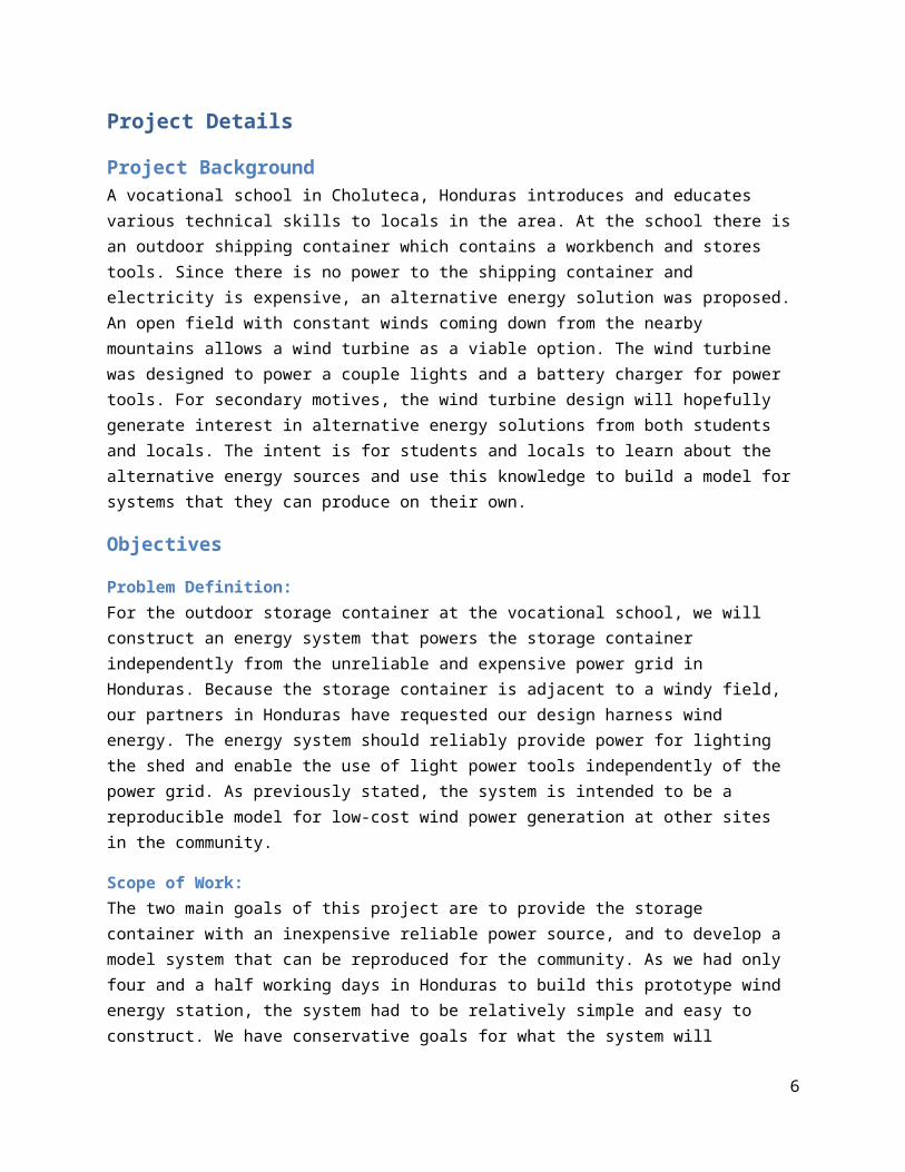
Project Background A vocational school in Choluteca, Honduras introduces and educates various technical skills to locals in the area. At the school there is an outdoor shipping container which contains a workbench and stores tools. Since there is no power to the shipping container and electricity is expensive, an alternative energy solution was proposed. An open field with constant winds coming down from the nearby mountains allows a wind turbine as a viable option. The wind turbine was designed to power a couple lights and a battery charger for power tools. For secondary motives, the wind turbine design will hopefully generate interest in alternative energy solutions from both students and locals. The intent is for students and locals to learn about the alternative energy sources and use this knowledge to build a model for systems that they can produce on their own.
4

Objectives
Problem Definition:For the outdoor storage container at the vocational school, we will construct an energy system that powers the storage container independently from the unreliable and expensive power grid in Honduras. Because the storage container is adjacent to a windy field, our partners in Honduras have requested our design harness wind energy. The energy system should reliably provide power for lighting the shed and enable the use of light power tools independently of the power grid. As previously stated, the system is intended to be a reproducible model for low-cost wind power generation at other sites in the community.
Scope of Work:The two main goals of this project are to provide the storage container with an inexpensive reliable power source, and to develop a model system that can be reproduced for the community. As we had only four and a half working days in Honduras to build this prototype wind energy station, the system had to be relatively simple and easy to construct. We have conservative goals for what the system will reliably power, nothing more demanding than some lightbulbs and a battery charger for power tools a few hours during the day. Additionally, this project will serve as an educational tool that introduces low-cost alternative energy generation to students at the vocational school. We modularized the components of the system in a way that makes it easy for the mechanically skilled students to maintain.
List of Deliverables:The delivery and construction of a wind power system will be the main deliverable of the project. This system should include a battery, charge controller, wind turbine, and an inverter. To ensure that this project can be reliably reproduced in other sites in the community, we will deliver comprehensive documentation regarding all components of the design at the end of the document.
Design Ideas
Research PerformedOur trip director, Miriam Simon’s thesis defense on wind turbines intended for individuals in developing countries proved useful in our initial design process. We learned a variety of design and construction concepts and suggestions as well as how the electrical system works. She had collected wind data for Choluteca which we used in our calculations. In terms of constructing the device, we learned Loctite was a good solution for fasteners coming loose with the vibrations of the device. Additionally, we learned the importance for the generator to be able to rotate on top of the post so the device can harness more energy. For the electrical system, we learned what components are necessary and how they interact with each other. We identified the importance of a diode to allow the current to only flow in one direction.
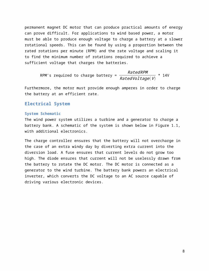
When selecting a generator, a permanent magnet DC motor was found to be most useful to convert motion to electricity because it can produce electricity without an initial power source to activate the magnet. Other motors demand that some electricity is used to magnetize an electromagnet before electricity can be generated. However, finding a permanent magnet DC motor that can produce practical amounts of energy can prove difficult. For applications to wind based power, a motor must be able to produce enough voltage to charge a battery at a slower rotational speeds. This can be found by using a
5
proportion between the rated rotations per minute (RPM) and the rate voltage and scaling it to find the minimum number of rotations required to achieve a sufficient voltage that charges the batteries.
RPM’s required to charge battery = Rated RPM
Rated Voltage (V ) * 14V
Furthermore, the motor must provide enough amperes in order to charge the battery at an efficient rate.
Electrical System
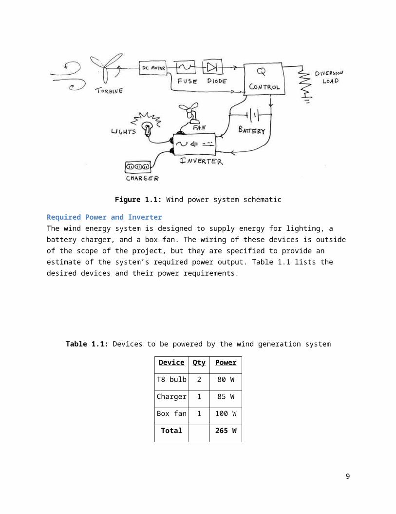
System SchematicThe wind power system utilizes a turbine and a generator to charge a battery bank. A schematic of the system is shown below in Figure 1.1, with additional electronics.
The charge controller ensures that the battery will not overcharge in the case of an extra windy day by diverting extra current into the diversion load. A fuse ensures that current levels do not grow too high. The diode ensures that current will not be uselessly drawn from the battery to rotate the DC motor. The DC motor is connected as a generator to the wind turbine. The battery bank powers an electrical inverter, which converts the DC voltage to an AC source capable of driving various electronic devices.
Figure 1.1: Wind power system schematic
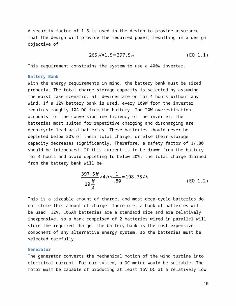
Required Power and InverterThe wind energy system is designed to supply energy for lighting, a battery charger, and a box fan. The wiring of these devices is outside of the scope of the project, but they are specified to provide an estimate of the system’s required power output. Table 1.1 lists the desired devices and their power requirements.
6
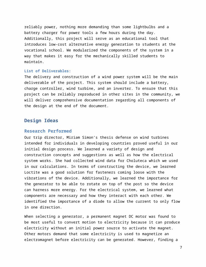
Table 1.1: Devices to be powered by the wind generation system
Device Qty Power
T8 bulb 2 80 W
Charger 1 85 W
Box fan 1 100 W
Total 265 W
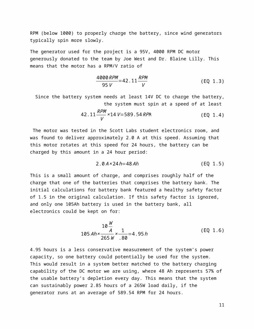
A security factor of 1.5 is used in the design to provide assurance that the design will provide the required power, resulting in a design objective of
265 W ×1.5=397.5W (EQ 1.1)
This requirement constrains the system to use a 400W inverter.
Battery BankWith the energy requirements in mind, the battery bank must be sized properly. The total charge storage capacity is selected by assuming the worst case scenario: all devices are on for 4 hours without any wind. If a 12V battery bank is used, every 100W from the inverter requires roughly 10A DC from the battery. The 20W overestimation accounts for the conversion inefficiency of the inverter. The batteries most suited for repetitive charging and discharging are deep-cycle lead acid batteries. These batteries should never be depleted below 20% of their total charge, or else their storage capacity decreases significantly. Therefore, a safety factor of 1/.80 should be introduced. If this current is to be drawn from the battery for 4 hours and avoid depleting to below 20%, the total charge drained from the battery bank will be:
397.5W
10 WA
× 4h× 1.80
=198.75 Ah (EQ 1.2)
This is a sizeable amount of charge, and most deep-cycle batteries do not store this amount of charge. Therefore, a bank of batteries will be used. 12V, 105Ah batteries are a standard size and are relatively inexpensive, so a bank comprised of 2 batteries wired in parallel will store the required charge. The battery bank is the most expensive component of any alternative energy system, so the batteries must be selected carefully.
GeneratorThe generator converts the mechanical motion of the wind turbine into electrical current. For our system, a DC motor would be suitable. The motor must be capable of producing at least 16V DC at a relatively low RPM (below 1000) to properly charge the battery, since wind generators typically spin more slowly.
7
The generator used for the project is a 95V, 4000 RPM DC motor generously donated to the team by Joe West and Dr. Blaine Lilly. This means that the motor has a RPM/V ratio of
4000 RPM95V
=42.11 RPMV (EQ 1.3)
Since the battery system needs at least 14V DC to charge the battery, the system must spin at a speed of at least
42.11 RPMV
× 14 V=589.54 RPM (EQ 1.4)
The motor was tested in the Scott Labs student electronics room, and was found to deliver approximately 2.0 A at this speed. Assuming that this motor rotates at this speed for 24 hours, the battery can be charged by this amount in a 24 hour period:
2.0 A ×24 h=48 Ah (EQ 1.5)
This is a small amount of charge, and comprises roughly half of the charge that one of the batteries that comprises the battery bank. The initial calculations for battery bank featured a healthy safety factor of 1.5 in the original calculation. If this safety factor is ignored, and only one 105Ah battery is used in the battery bank, all electronics could be kept on for:
105 Ah ×10 W
A265 W
× 1.80
=4.95 h (EQ 1.6)
4.95 hours is a less conservative measurement of the system’s power capacity, so one battery could potentially be used for the system. This would result in a system better matched to the battery charging capability of the DC motor we are using, where 48 Ah represents 57% of the usable battery’s depletion every day. This means that the system can sustainably power 2.85 hours of a 265W load daily, if the generator runs at an average of 589.54 RPM for 24 hours.
The generator is the limiting reagent of this system’s power capacity. A low output current at the required battery charging voltage results in slow charging. The project could be scaled up with an additional battery once a more efficient generator is found. Therefore, the final design will use one 12V, 105 Ah batt
ery to serve as the battery bank.
Mechanical System
Calculations for mechanical properties Through communication with Larry in regards to the intended design of the wind turbine structure, the maximum diameter pipe he was able to find locally was a 4” diameter steel pipe. In order to insure that this size pipe would be adequate for our design, some rough calculations were done to ensure the pipe would not fail. This involved some very rough assumptions, such as those related to the weights of the generator, turbine blades, tail, and mount support. Also, the drag force was calculated using Equation 2.1, assuming that the radius of the turbine blades produced a full circular obstruction of the wind path.
8
FD=12∗ρ∗v2∗Cd∗A (EQ 2.1)
FD=Drag Force ( N )
ρ=Air Density ( kgm3 )
v=Air velocity(ms )
Cd=Coefficient of Drag (unitless )
A=Frontal Area (m2 )
For full sample calculations, see Appendix 1. This calculation produced an estimated drag force of roughly 93 N. Using this value, a rough estimate of reaction forces was found. Figure 2.1 shows the free-body diagram implemented for this analysis. Referencing Figure 2.1, a refers to the distance from the roof support to the turbine support, brefers to the distance from the roof support to the base support. The calculations are performed using these distances as well as the forces FD (drag force), W (weight force), FR (roof support reaction force), and FBot (base support reaction force). See Appendix 1 for full sample calculations.
Figure 2.1: Force Analysis Free-Body Diagram
These calculations produced the reaction forces at the base support (~300 N) and the roof support (~800 N). With the force analysis complete, these numbers were then used to perform a stress analysis to verify the acceptability of the 4” diameter steel pipe. For this analysis, a yield strength of steel was assumed, at 207 MPa. The stress analysis involved a tensile stress due to the turbine weight (Equation 2.2), as well as a radial stress due to the reaction forces (Equation 2.3). In the radial stress, a thin-walled vessel was
assumed for simplicity despite the value of rt= pipe radius
pipe thickness greater than 10. In Equation 2.3, the
maximum stress is found where r=ri.
9
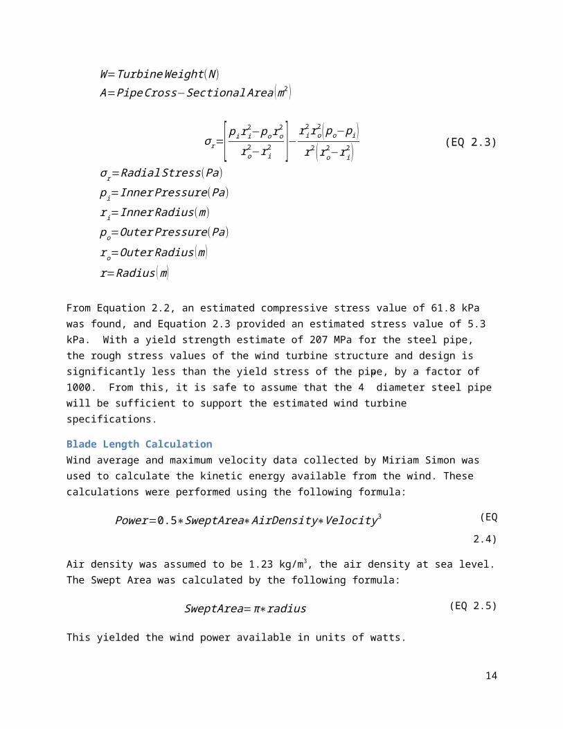
σ=WA (EQ 2.2)
σ=Tensile Stress (Pa)W =TurbineWeight (N )
A=PipeCross−Sectional Area ( m2 )
σ r=[ pi r i2−po ro
2
ro2−r i
2 ]−r i2 ro
2 ( po−p i )r2 (ro
2−ri2 )
(EQ 2.3)
σ r=Radial Stress(Pa)pi=Inner Pressure(Pa)ri=Inner Radius (m)po=Outer Pressure (Pa)ro=Outer Radius (m )r=Radius (m )
From Equation 2.2, an estimated compressive stress value of 61.8 kPa was found, and Equation 2.3 provided an estimated stress value of 5.3 kPa. With a yield strength estimate of 207 MPa for the steel pipe, the rough stress values of the wind turbine structure and design is significantly less than the yield stress of the pipe, by a factor of 1000. From this, it is safe to assume that the 4” diameter steel pipe will be sufficient to support the estimated wind turbine specifications.
Blade Length CalculationWind average and maximum velocity data collected by Miriam Simon was used to calculate the kinetic energy available from the wind. These calculations were performed using the following formula:
Power=0.5∗SweptArea∗AirDensity∗Velocity 3 (EQ 2.4)
Air density was assumed to be 1.23 kg/m3, the air density at sea level. The Swept Area was calculated by the following formula:
SweptArea=π∗radius (EQ 2.5)
This yielded the wind power available in units of watts.
However, a wind turbine cannot harness all of the available wind power as determined by German physicist Albert Betz. The Betz Limit states that no more than 16/27 of the wind’s kinetic energy can be converted into mechanical energy. This does not take into account inefficiencies in the turbine system. Once those inefficiencies are also taken into account, only 35-45% of the wind’s kinetic energy can be converted to the mechanical power responsible for turning the rotor. Therefore, for the calculations
10
performed in this project, it was assumed that a conservative 35% of wind’s calculated kinetic energy would be converted into the mechanical energy available to the rotor powering the generator.1
The mechanical power available for electric generation was then converted to kilowatts and multiplied by twenty four hours / day to determine on average how many kW*h could be produced per day. The results are summarized in Table 2.1.
1 (Luscher 2011)
11

Table 2.1: Average available kW*h
Radius (m)
Average kW*h available for average wind speeds
Average kW*h available for maximum wind speeds
0.5 0.105244901 1.4559973931 0.434135215 6.0059892451.25 0.680802951 9.4184831341.35 0.79481826 10.995813641.5 0.982285739 13.5893091.75 1.338583579 18.518466842 1.749696472 24.205956652.1 1.929489844 26.69328553
Based on these results it was determined that a one meter blade length was necessary to produce the 400 watt*hours needed per day to power the items requested by the Overholts.
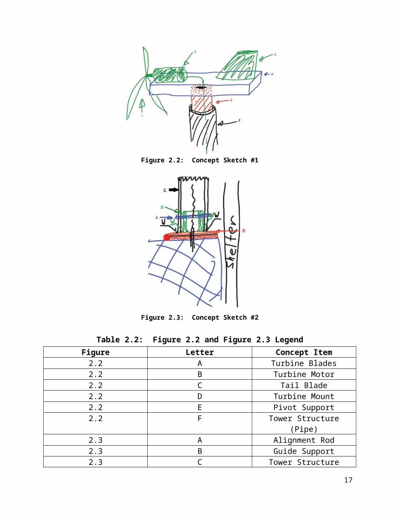
Diagrams of Structural ComponentsThe design process for the wind turbine project was heavily based off a pre-existing home-made wind turbine project completed by Miriam Simon (Simon 2012). To get a grasp of the concept modified to the scope of this project, the team drafted up some very rough concept design sketches, as shown in Figures 2.2 and 2.3. See Table 2.2 for the legend to each figure.
12

Figure 2.2: Concept Sketch #1
Figure 2.3: Concept Sketch #2
Table 2.2: Figure 2.2 and Figure 2.3 LegendFigure Letter Concept Item
2.2 A Turbine Blades2.2 B Turbine Motor2.2 C Tail Blade2.2 D Turbine Mount2.2 E Pivot Support2.2 F Tower Structure (Pipe)2.3 A Alignment Rod2.3 B Guide Support2.3 C Tower Structure (Pipe)2.3 D Structure Hinge
Referring to Figure 2.2, the intended design involves the turbine motor and blades, along with the tail, mounted to a steel support acting as the turbine mounting base. Welded to this base would be a pipe that
13
would fit inside the tower structure or pipe. This inner diameter pipe would fit inside the tower pipe, with a minimum clearance. Lubrication would be added to the clearance fit to allow for the turbine to rotate freely with the change in prevailing wind. The mounting location of the pivot support to the turbine mount will vary depending on the weight distribution of the motor, blades, and the tail. The green, unlabeled line represents the motor wiring to be guided down through the storage container.
Figure 2.3 shows the intended lower mount. The tower pipe will extend down to the roof of the storage container, and will be welded to the top plate of a large hinge. The bottom plate of the hinge will be rigidly mounted to the storage container roof. Also mounted to the top plate of the hinge, inside the weld of the tower pipe will be a guide support, similar to the pivot support. Through both the tower pipe and the guide support will be a guide/alignment to both pipes meant to prevent rotation and translation of the tower pipe, ensuring security of the tower. The black, unlabeled line through the storage container represents the motor wiring.
Overall, the design will stretch roughly five feet above the apex of the roof of the shelter to allow for free rotation of the turbine without collision with the shelter roof. To further secure the tower to the shelter by way of a mounting bracket located at the apex of the shelter roof. This mounting bracket will further secure the tower and increase the safety regarding the project along with the maximum acceptable wind speed the turbine can handle.
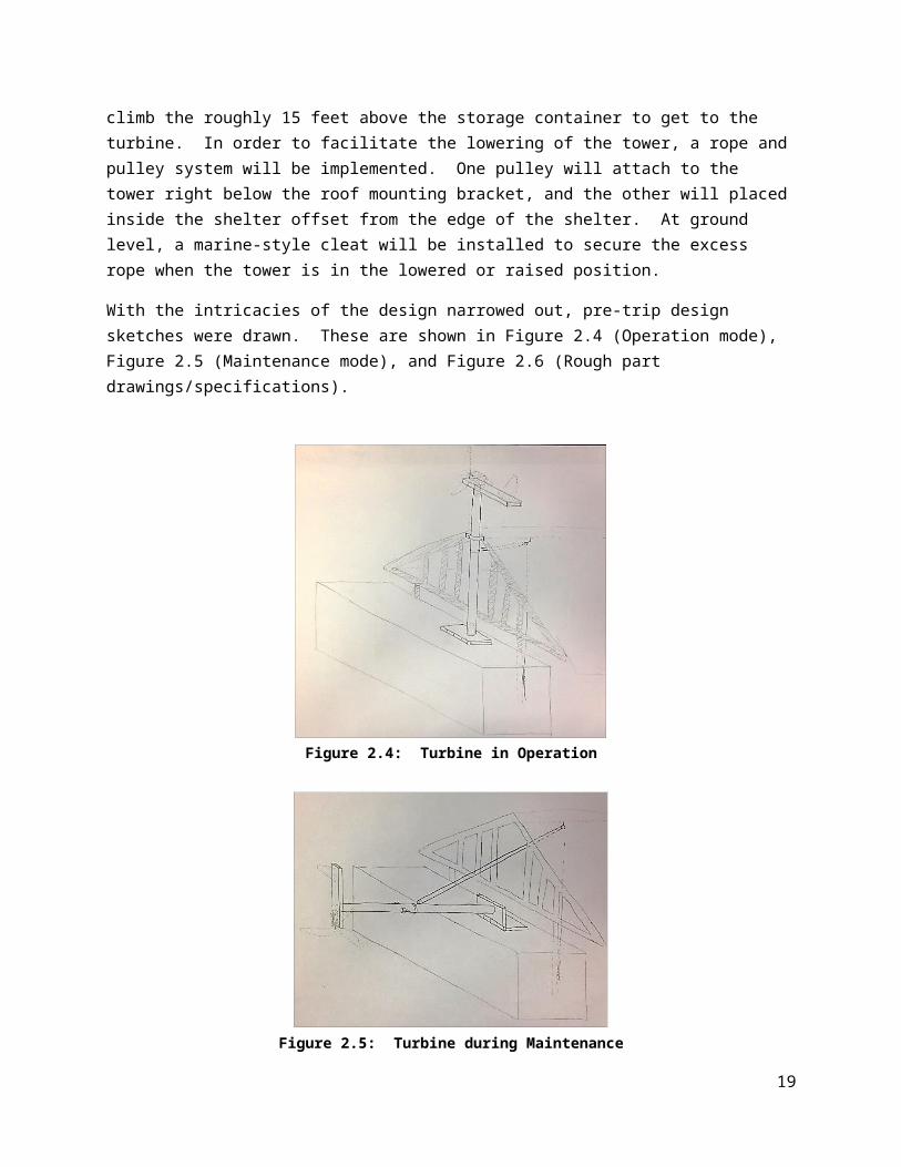
The purpose of the hinged support at the bottom was meant to allow for easier maintenance of the system. If a problem were to arise with the turbine, the top mounting bracket can be removed, and the tower lowered towards the ground and fixed, rather than requiring someone to climb the roughly 15 feet above the storage container to get to the turbine. In order to facilitate the lowering of the tower, a rope and pulley system will be implemented. One pulley will attach to the tower right below the roof mounting bracket, and the other will placed inside the shelter offset from the edge of the shelter. At ground level, a marine-style cleat will be installed to secure the excess rope when the tower is in the lowered or raised position.
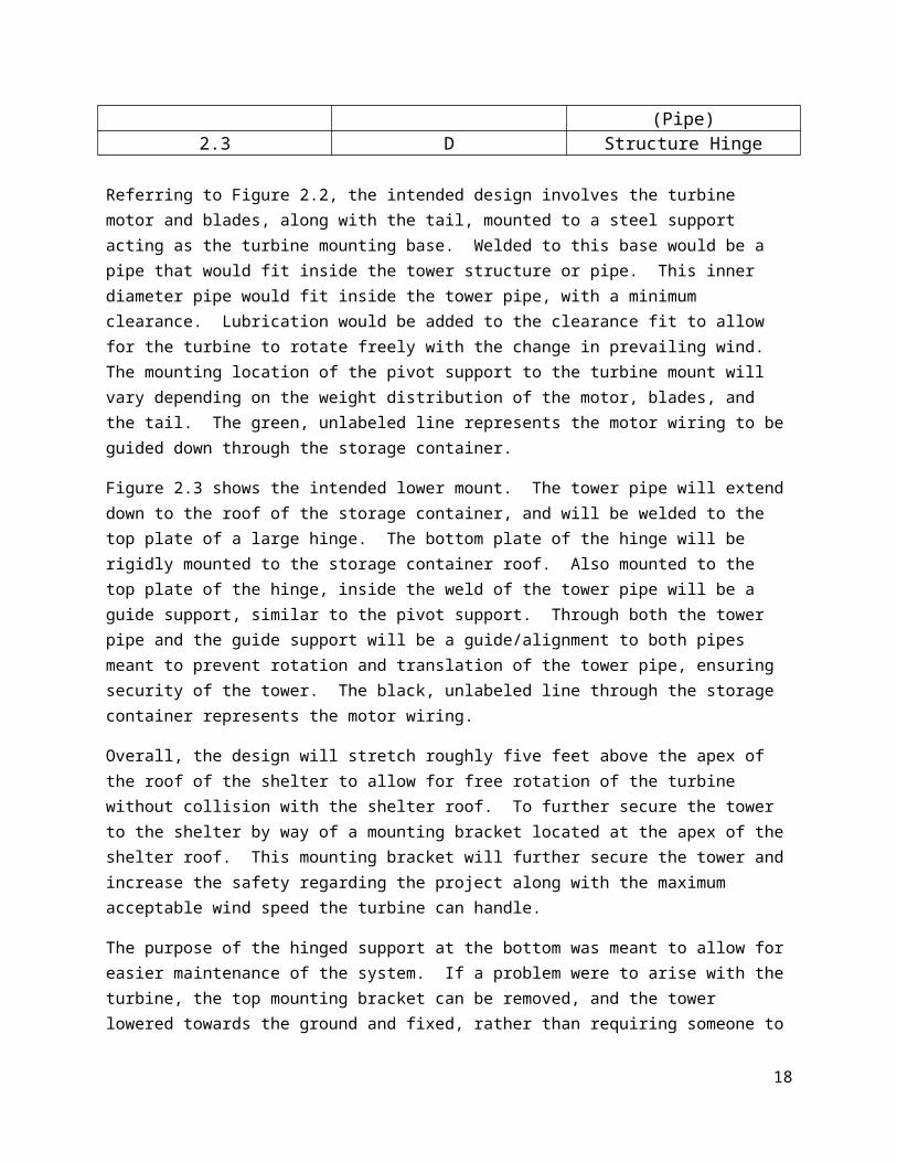
With the intricacies of the design narrowed out, pre-trip design sketches were drawn. These are shown in Figure 2.4 (Operation mode), Figure 2.5 (Maintenance mode), and Figure 2.6 (Rough part drawings/specifications).
14

Figure 2.4: Turbine in Operation
Figure 2.5: Turbine during Maintenance
Figure 2.6: Turbine Part Specifications
15

The final design comes with some modified specifications from the concept sketches. The tower mount should optimally be a steel rectangular tube or C-channel. This would provide a lightweight base at the top of the tower, yet provide ample strength and rigidity to prevent failure of the mount. Also, the hinge at the bottom support will most likely need to be specially fabricated. This will allow for the needed customization relative to this project, and the use of resources available at the vocational school.
Along with the guide rope mounted to the tower, two guide cables will be mounted to the tower increasing the rigidity of the overall tower structure. These two guide cables will extend in opposite directions, both parallel to the storage container. One will be mounted near the door-side of the storage container, the other mounted to the back of the storage container. The mounts at the top of the pole will involve a clip in or screw-tight carabineer on either side. An eyelet of doubled-back steel cable will be attached to the carabineer. At the mount on the storage container, an eyelet loop will be mounted to the storage container, and the doubled-back steel cable will be connected to the eyelet.
This design will provide optimum function and safety while allowing for simple maintenance when problems arise. Another added benefit of this design will allow for lowering of the turbine during high wind situations, further adding to the safety surrounding the system.
Sustainability and MaintainabilityThe established system will be able to produce electricity without any constant human interaction or use of limited resources. The presence of wind is the only requirement needed to produce electricity to charge the battery. Furthermore, because the system involves the use of a battery system, the energy generated from the wind is capable of being stored in the batteries, effectively allowing the system to provide electricity for a limited time when insufficient wind is present. The tail fin design is capable of directing the propeller to face the incoming wind to further maximize its efficiency without human interaction.
During the trip, the vocational school staff will be educated on how the system functions electrically and mechanically so that unpredicted damages can be handled appropriately. Due to the potentially destructive high winds and the height at which the turbine is mounted, a lowering mechanism will be installed so that the turbine can be protected from high-speed winds and repaired at a safe height. Additionally, switches in the circuitry will be installed so that repairs can be made without the risk of electrical shock.
Pre-Trip Progress Summary
Schedule – Prior to DepartureIn the eleven weeks prior to departure, preparations were made to ease in-country experience and implementation. The following is a breakdown of the week to week activities for the project:
January 4th - Introduction and Brainstorming Project Ideas January 11th – Project decision and Project management presentation January 18th – Project Proposal, begin work on project
16
Date Wind Other
17-Mar Arrive in Choluteca Arrive in Choluteca18-Mar Beach day Beach day19-Mar Assemble blades and rear hinge and
stand/tower and mount3/20: Split
Finish assemble and Begin wiring Begin Aquaponic and Bike Project
3/21: Split
Finish wiring and begin testing Aquaponic and Bike Projects
22-Mar Complete Aquaponic and Bike Projects
23-Mar Troubleshooting/ Depart for Tegucigalpa
Troubleshooting/ Depart for Tegucigalpa
24-Mar Return home Return home
January 25th – Ongoing Project work February 1st - Ongoing Project work February 8th – Project Design Presentation and Ongoing Project work February 15th - Ongoing Project work February 22nd - Ongoing Project work February 29th – Pre-Departure Project Presentation and Ongoing Project work March 7th – Final Wrap up of Pre-Departure Project work March 15th – Packing party March 17th - Depart Columbus and arrive in Choluteca
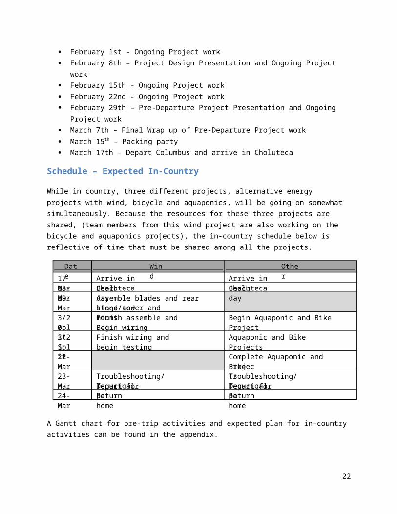
Schedule – Expected In-Country
While in country, three different projects, alternative energy projects with wind, bicycle and aquaponics, will be going on somewhat simultaneously. Because the resources for these three projects are shared, (team members from this wind project are also working on the bicycle and aquaponics projects), the in-country schedule below is reflective of time that must be shared among all the projects.
A Gantt chart for pre-trip activities and expected plan for in-country activities can be found in the appendix.
Materials, Tools and CostsA preliminary cost analysis below gives an idea of the monetary investment of this project:
17
Item Unit Cost
Generator 50 Amp, 95V, 4000 RPM $0.00On behalf of Joe West and Dr. Blaine Lilly
Blocking Diode 40 Amp, 600V $7.98 GudCraft CD5.0 12VDC wind charge controller $99.26 1x Trojan Battery, 12V, 105 Ah $142.86 Cobra Inverter 400W $26.70 300W diversion load resistor $17.98 Mounting Gear (Pulley and frames support parts) $148.33Miscellaneous material to be found in Honduras $28.98Wiring (30A/40A capacity) and electrical equipment $22.29Grounding rod $12.00Total $506.38
We brought items with us as well as purchased some things in country. An overview of each type is listed below.
Items Brought
Alternator Inverter Turbine blades Mounting plate Marine cleat Pulley system Charge controller Zip-ties Switches Diode Resistors
Items Obtained and Tools Used in Honduras
Wiring/fasteners Galvanized steel rods for support structure Grounding rods Rope Scrap metal for tail Materials for a gear system Hinge Battery Welding
18
Power drill Tools for handling the scrap metal
In-Country ImplementationThe team successfully traveled to Choluteca, Honduras, installed, and implemented the wind turbine design described previously. The initial design was successfully constructed and implemented, but due to reduced electrical output, the design was modified. With the adjustments to the design, the team worked to increase the motor output. In doing so, the result proved ineffective, and led to a post-trip design construction to be sent down to Choluteca for implementation.
Mechanical/Structural System
Wind Turbine AssemblyOnce on site in Honduras, the wind turbine construction went very smoothly. On the first work day, much progress was made in the preparation for construction. The tower pipe was purchased and cut to size, general structure measurements were taken to use for sizing and planning, the hinge system parts were found and cut to size in preparation for installation on the storage shelter, the strap clamp was cut and bent to shape, and the c-channel sections were cut in preparation for welding.
The next day, the overall tower construction really started to come together. With the help of Hever, the on-site welder at the vocational school, the c-channel pieces were welded together, the tail and support pipe were welded to the c-channel, the hinge assembly was welded together (hoops welded to the hinge plate and hoops welded to the storage container), the pulley system was installed, a notch in the shelter roof was cut in preparation for the tower pipe, and the tower pipe was prepared for mounting by drilling holes for the guide wire and pulley eyebolts, as well as the alignment pin for the bottom pipe. See Figure 7 through 9 for the welded hinge assembly, the motor and tail mounted to the c-channel, and the installed pulley system.
Figure 7: Hinge Assembly Figure 8: Motor and Tail C-Channel
19
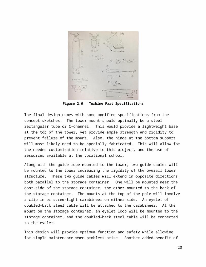
Figure 9: Pulley System
The third day, the structure came together as planned. The tower pipe was mounted to the hinge and secured via the guide wires and the pulley system. Once the generator was installed on the c-channel, the wiring was completed, and the blade hub was installed. With this, the generator assembly was installed on the tower pipe, and successfully lifted up using the pulley system and some extra lifting by the team. Figure 10 shows the installation of the wind turbine.
20

The turbine worked quite well, and the construction accurately matched the pre-trip design. Once installed, the turbine blades spun rather well with input from the local winds. It was clear why this site was chosen for implementation of a wind turbine due to the consistent wind that would supply the turbine.
During and after the tower structure and turbine were installed, the electrical system was installed. Due to an incompatible charge controller, the wiring and electrical system was completed except for the installation of the charge controller. All other connections were made, and instructions were left for the charge controller to be plugged into the system once it is shipped down to the location.
Design ComplicationsOnce the turbine structure was assembled, raised, and visibly working, electrical testing was performed to ensure proper operation. Using a multimeter, the output voltage from the generator was measured at a varying range of wind speeds. The outputs from low to high wind speeds were measured. From this test, an output of roughly 6V was measured at high wind speeds. In order to charge the battery, a 12V input was needed.
RedesignFrom this complication, a design change was needed in order to step up the speed from the blades to the generator input. Multiple designs were brought up that could solve the problem. Initially, a gearbox from
21
Figure 10: Turbine Installation
an old car was sought, but due to the high cost and high weight, a different design solution was implemented.
Chacho, the vocational school’s resident handyman, took some of the team members to a motorcycle repair store, where his nephew worked. After searching through multiple bins of spare parts, we were graciously given multiple sprockets and chains, along with shafts and bearings to implement our design changes.
In our set of new parts, we were given (2) 41 tooth sprockets, (2) 15 tooth sprockets, (2) full-length motorcycle chains, (2) small shafts, and (4) bearings. With these pieces, we designed a 2-step gear train to provide a roughly 7.5:1 gear ratio. A rough sketch of this redesign is provided in Figure 11.
Figure 11: Redesign Sketch
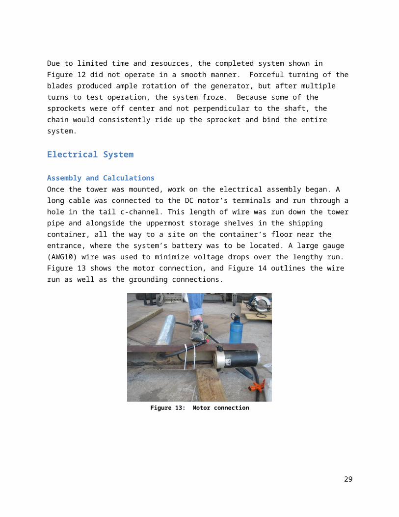
With the pieces received from the motorcycle repair store, the team went about modifying the turbine design to hold the needed gear system. The structure was modified to hold the two shafts with the given bearings and scrap steel found at the vocational school. The general design shown in Figure 11 was followed, with minor modifications made in bearing placement, shaft support mounting structure, and other general modifications. The modified final system is shown in Figure 12.
22

Figure 12: Modified Design Structure
Due to limited time and resources, the completed system shown in Figure 12 did not operate in a smooth manner. Forceful turning of the blades produced ample rotation of the generator, but after multiple turns to test operation, the system froze. Because some of the sprockets were off center and not perpendicular to the shaft, the chain would consistently ride up the sprocket and bind the entire system.
Electrical System
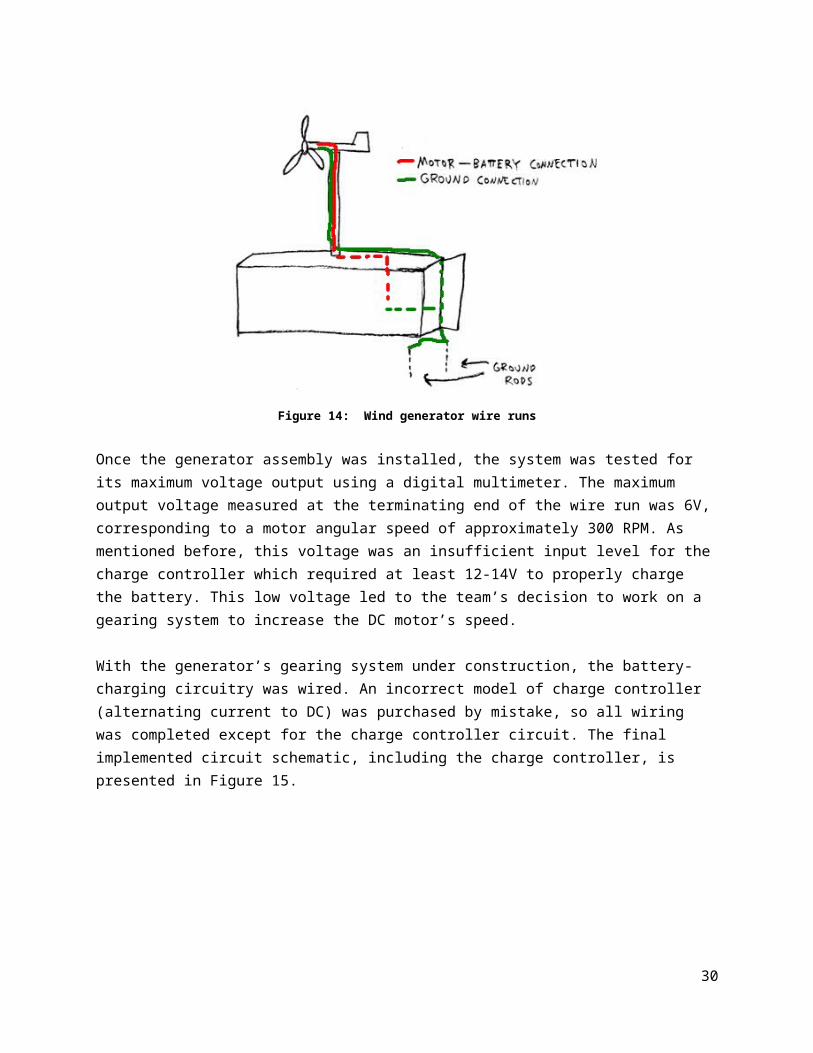
Assembly and CalculationsOnce the tower was mounted, work on the electrical assembly began. A long cable was connected to the DC motor’s terminals and run through a hole in the tail c-channel. This length of wire was run down the tower pipe and alongside the uppermost storage shelves in the shipping container, all the way to a site on the container’s floor near the entrance, where the system’s battery was to be located. A large gauge (AWG10) wire was used to minimize voltage drops over the lengthy run. Figure 13 shows the motor connection, and Figure 14 outlines the wire run as well as the grounding connections.
Figure 13: Motor connection
23

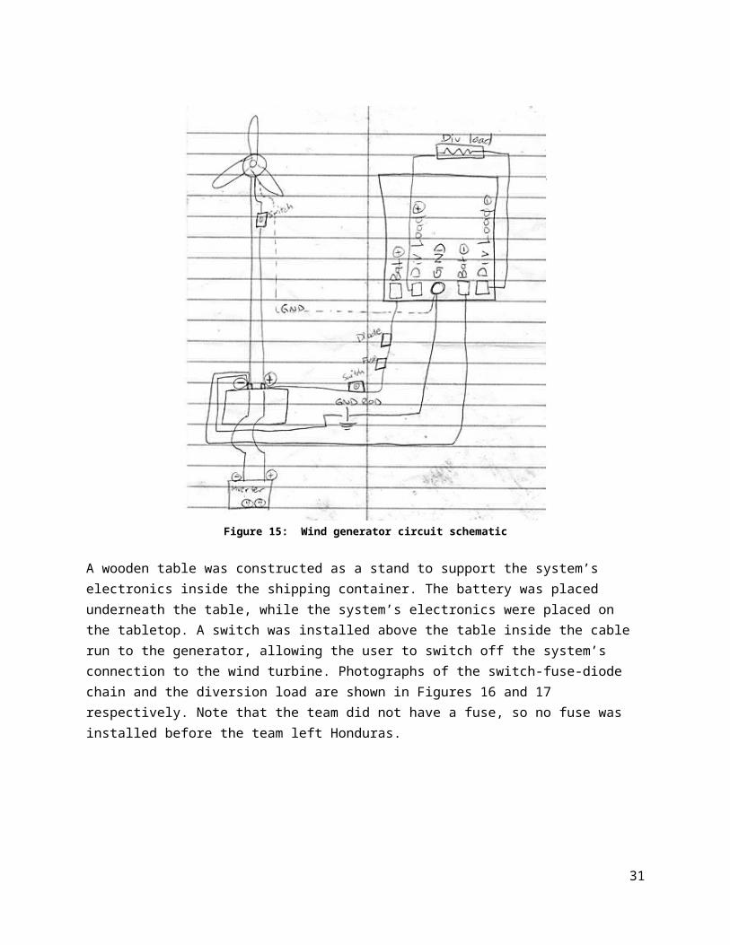
Figure 14: Wind generator wire runs
Once the generator assembly was installed, the system was tested for its maximum voltage output using a digital multimeter. The maximum output voltage measured at the terminating end of the wire run was 6V, corresponding to a motor angular speed of approximately 300 RPM. As mentioned before, this voltage was an insufficient input level for the charge controller which required at least 12-14V to properly charge the battery. This low voltage led to the team’s decision to work on a gearing system to increase the DC motor’s speed.
With the generator’s gearing system under construction, the battery-charging circuitry was wired. An incorrect model of charge controller (alternating current to DC) was purchased by mistake, so all wiring was completed except for the charge controller circuit. The final implemented circuit schematic, including the charge controller, is presented in Figure 15.
24
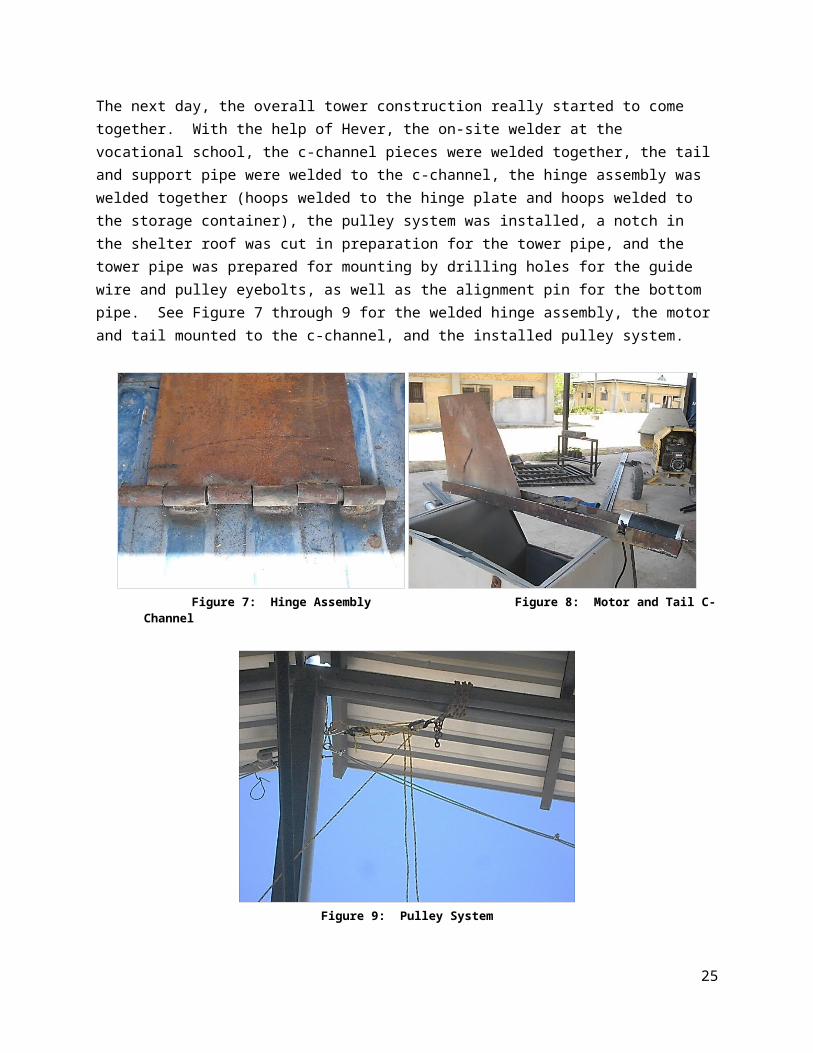
Figure 15: Wind generator circuit schematic
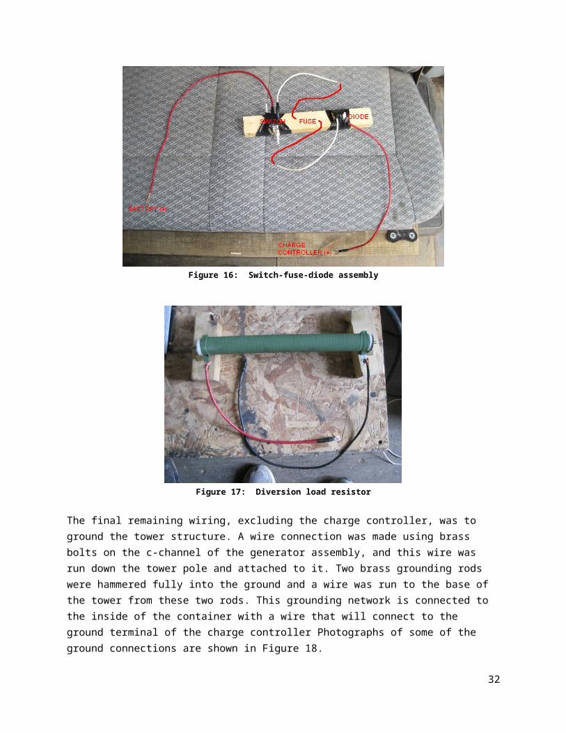
A wooden table was constructed as a stand to support the system’s electronics inside the shipping container. The battery was placed underneath the table, while the system’s electronics were placed on the tabletop. A switch was installed above the table inside the cable run to the generator, allowing the user to switch off the system’s connection to the wind turbine. Photographs of the switch-fuse-diode chain and the diversion load are shown in Figures 16 and 17 respectively. Note that the team did not have a fuse, so no fuse was installed before the team left Honduras.
25
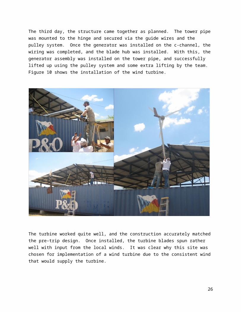
Figure 16: Switch-fuse-diode assembly
Figure 17: Diversion load resistor
The final remaining wiring, excluding the charge controller, was to ground the tower structure. A wire connection was made using brass bolts on the c-channel of the generator assembly, and this wire was run down the tower pole and attached to it. Two brass grounding rods were hammered fully into the ground and a wire was run to the base of the tower from these two rods. This grounding network is connected to the inside of the container with a wire that will connect to the ground terminal of the charge controller Photographs of some of the ground connections are shown in Figure 18.
26
Figure 18: Grounding connections at the bottom of tower (left) and from grounding rod to inside container (right)
ComplicationsA DC motor is not an ideal generator, but it is very difficult to find other inexpensive low-RPM generators. The DC motor did not output sufficient voltage to charge the battery with normal wind speeds. Also, the charge controller that the team took to Honduras was not designed for DC-to-DC systems, so another controller had to be ordered and sent down separately with the new generator assembly.
Post-Trip Summary
Post-Trip Modifications and Recommendations
Mechanical SystemWith the finished turbine gearing design in place at the vocational school, there are some design changes that would allow the design to work as desired. If the sprockets were realigned with the shafts to be directly in the center of the sprocket, as well as perpendicular to the shaft, the chain would have less of an opportunity to ride up the sprocket during rotation.
Also, if more thought and design was put into the shaft mounting structure, the design would be much more viable for use. Due to limited time and resources, the mounting structure was not thoroughly thought out, leading to errors in the construction that prevented the end result from working correctly.
Due to the complications stemming from the modified design, the final product installed in Choluteca was a non-working model. In order to complete the project, it was decided that the team would construct a new generator and turbine system at Ohio State to send down. This action would provide a smooth-working final product to install at the vocational school.
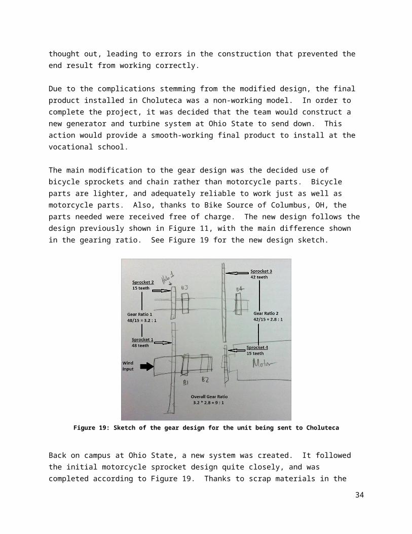
The main modification to the gear design was the decided use of bicycle sprockets and chain rather than motorcycle parts. Bicycle parts are lighter, and adequately reliable to work just as well as motorcycle parts. Also, thanks to Bike Source of Columbus, OH, the parts needed were received free of charge. The new design follows the design previously shown in Figure 11, with the main difference shown in the gearing ratio. See Figure 19 for the new design sketch.
27
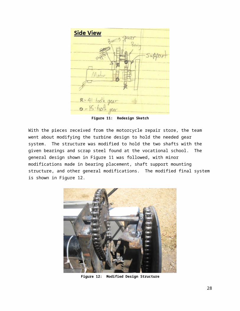
Figure 19: Sketch of the gear design for the unit being sent to Choluteca
Back on campus at Ohio State, a new system was created. It followed the initial motorcycle sprocket design quite closely, and was completed according to Figure 19. Thanks to scrap materials in the Scott and Baker Lab Machine shops and a motor donation from Mrs. Miriam Simon, the only materials purchased for the new mechanism was some scrap aluminum material and shaft bearings for each shaft.
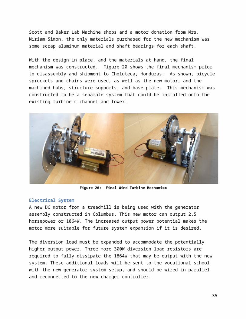
With the design in place, and the materials at hand, the final mechanism was constructed. Figure 20 shows the final mechanism prior to disassembly and shipment to Choluteca, Honduras. As shown, bicycle sprockets and chains were used, as well as the new motor, and the machined hubs, structure supports, and base plate. This mechanism was constructed to be a separate system that could be installed onto the existing turbine c-channel and tower.
Figure 20: Final Wind Turbine Mechanism
28
Electrical SystemA new DC motor from a treadmill is being used with the generator assembly constructed in Columbus. This new motor can output 2.5 horsepower or 1864W. The increased output power potential makes the motor more suitable for future system expansion if it is desired.
The diversion load must be expanded to accommodate the potentially higher output power. Three more 300W diversion load resistors are required to fully dissipate the 1864W that may be output with the new system. These additional loads will be sent to the vocational school with the new generator system setup, and should be wired in parallel and reconnected to the new charger controller.
With the electrical system nearly complete, only a few extra wire connections must be made. When the Xantrex C35 wind charge controller arrives in Honduras, five connections must be made for the system to be operational:
1) Battery (+) to Switch-fuse-diode assembly to Bat(+) charge controller input2) Battery (-) to Bat(-) charge controller input3) Ground wire to charge controller ground input4) Diversion load to charge controller diversion load (+) input5) Diversion load to charge controller diversion load (-) input
A 20A fuse should also be installed between the switch and diode assembly since the new motor is rated to put out a maximum of 18A. The required wires are already in place, so a fuse should be purchased at a local hardware store and mounted in between the two and wired as denoted in Figure 16. This fuse will prevent the system from driving the charge controller with inappropriately high currents.
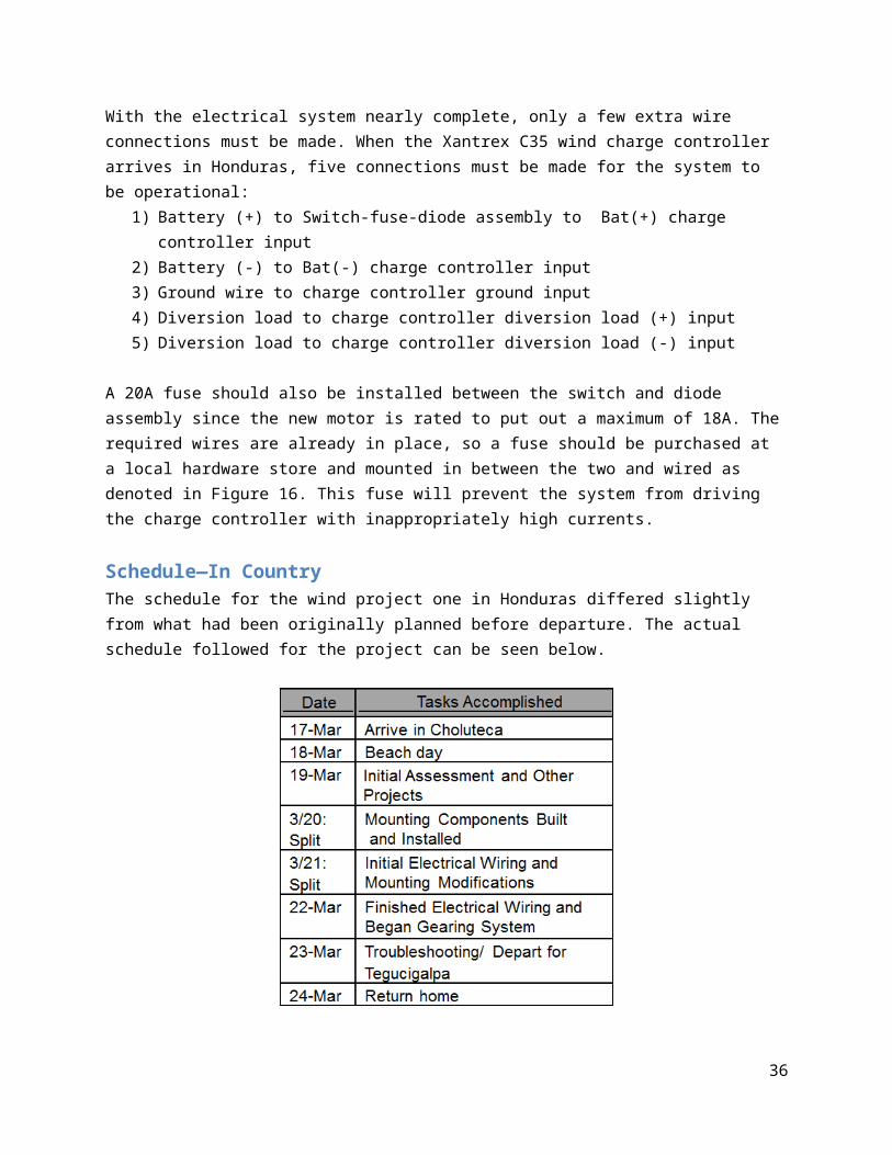
Schedule—In CountryThe schedule for the wind project one in Honduras differed slightly from what had been originally planned before departure. The actual schedule followed for the project can be seen below.
29
Materials and Costs
The total cost prior to going to Honduras was $200.54. This included material for crafting the blades and components such as the pulley system and mounting parts. The generator was provided without charge on behalf of Dr. Lilly and Joe West. Also, parts for the mounting bracket were obtained without charge by using scrap materials.
The total expenditure in Honduras totaled to $305.84. This included grounding rods, electrical wire, and a battery. Metal parts were crafted from scrap metal and used to build the structure. Special metal parts such as chains and sprockets were obtained via a motorcycle repair shop and the generous donation by the owner.
The total cost for the entire project totaled to $506.38. This value was within the limit of $100 per group member which was matched by World Gospel Mission for a total of $1600. The extra money was directed towards other, projects occurring at that time.
Acknowledgements--Chacho (site setup, and overall assistance with all aspects of the project)--Hever (constant welding and assistance with all projects)--Chacho’s nephew (motorcycle sprockets, chains, bearings, shafts)--Bike Source, Sawmill, Columbus, OH (box of bike sprockets and chains for use on new design)-- Dr. Blaine Lilly and Joe West (DC permanent magnet motor)--Scott Lab and Baker Lab Machine Shops (tool and equipment use, and scrap materials)--Office of International Affairs-- Dr. John Merril, Dr. Roger Dzwonczyk, and Miriam Simon
30
Appendix
31
ReferencesSimon, Miriam. "Wind Generator Information." Thesis Defense. The Ohio State University,
Columbus. 11 JAN 2012. Lecture.
Luscher, Prof. "ME 563 Design Project: Design of a Transmission for a Small Scale Wind Turbine." 2011.
32

CalculationsRequired Turbine RPM:
RPM’s required to charge battery = Rated RPM
Rated Voltage (V ) * 14V
RPM’s required to charge battery = 1200 RPM
30(V ) * 14V = 560 RPM
Sample calculations
Figures and Tables
Gantt chart – Pre-Departure:
Gantt chart – In country:
33
Preliminary Design Drawings for Mechanical Structure
34
35
Instruction Manuals and Documentation
How To/Maintenance for structureProper lowering of the turbine tower is advised by using the assistance of multiple people. Though it could be done with one person, it is not advised to protect the safety of the operator(s), but also the safety of the equipment.
If it is determined that the turbine tower should be lowered (due to required maintenance, winds exceeding the maximum allowable speed, prevent damage during inclement weather, etc.), please follow these steps.
Lowering of Turbine Tower1. Person 1, ascend to the roof of the storage container, and use a ladder to reach the top mounting
bracket.2. Person 2, assure that the maintenance rope is secure to the rope cleat.3. Person 1, unbolt the top mounting bracket, making the rope and guide cables the only source of
attachment for the tower.4. Person 1, descend from the roof of the storage container.5. Person 2, slowly lower the turbine tower in a controlled manner. Tightly secure the rope to the
rope cleat.6. With the turbine safely lowered, any maintenance, storage, etc. can be performed.
Raising of Turbine Tower1. Person 2, unsecure the rope from the rope cleat, and slowly raise the turbine tower2. Person 1, ascend to the roof of the storage container.3. Person 2, raise the turbine tower to the point of anchoring.4. Person 1, replace the mounting bracket in its location on the tower pipe, and bolt the bracket back
into the shelter roof.5. Person 2, tightly secure the rope to the rope cleat.
36