Embed Size (px)
Citation preview
Journal of Manufacturing Systems Vol. 16/No. 3 1997
Alternative Approaches to Solve the Multi-Floor Facility Layout Problem Russell D. Meller, Auburn University, Auburn, Alabama Yavuz A. Bozer, University of Michigan, Ann Arbor, Michigan
Abstract Alternative approaches to solve the multi-floor facility
layout problem are compared in this paper. In particular, because the multi-floor facility layout problem is NP-com- plete, the effectiveness of heuristically solving it via a single- stage approach (where each department, unless it is fixed or constrained by the user, is allowed to occupy any floor dur- ing the execution of the heuristic) versus a two-stage approach (where in the first stage each department is per- manently assigned to one of the floors and in the second stage the layout is determined for each floor) is evaluated. Generally speaking, given no limits on run times, one would expect the single-stage approach to outperform the above two-stage approach because the former allows depart- ments to change floors during the execution of the algo- rithm. However, if the run times are required to be reason- able and comparable, it is no longer clear that the single- stage approach will lead to superior solutions because it has to explore a larger solution space. The performance of the two-stage approach, on the other hand, depends on the quality of the floor assignments obtained in stage one. Instrumental to the quality of these assignments is a newly developed simplified formulation with a linear objective to optimize the inter-floor handling cost in stage one. The resulting two-stage approach is then evaluated with respect to a single-stage approach using various test problems. The evaluation includes a variation of the above two-stage approach where the floor assignments obtained in stage one are not permanent; that is, departments are allowed to change floors in the second stage. The evaluation indicates that the proposed two-stage approach compares quite well to both of the other approaches. The results obtained by the two-stage approach are shown from a data set that is based on a real-world manufacturing facility.
Keywords: Facility Layout, Multi-Floor Manufacturing System Design, Production and Operations Management, Generalized Quadratic Assignment Problem
1. Introduction The facility layout problem is generally defined
as finding a feasible, nonovedapping arrangement of departments (with given area requirements) with- in a facility to minimize the interaction cost between the departments. Interaction cost between two departments is typically expressed as the flow times
the distance between the departments. In general, departments have unequal area requirements, and some of them may be constrained a priori to certain locations within the facility. Because the single- floor facility layout problem is NP-complete, 1 many heuristics have been developed for it. 2
The multi-floor facility layout problem, on the other hand, encompasses all aspects of the single- floor facility layout problem, and in addition, it includes vertical flows and area constraints for indi- vidual floors. Vertical flows must utilize a lift, which is defined here as a generic vertical material han- dling device. Moreover, because it is assumed that in a manufacturing setting departments cannot be split across floors, some layouts may not be area-feasible in a multi-floor problem?
While multi-floor manufacturing facilities are not as common as single-floor facilities, due to the advances in vertical material handling technology in the late 1980s and early 1990s, "many firms are likely to con- sider renovating or constructing multi-floor buildings, particularly in those cases where land is limited? '3 In fact, the authors have visited numerous new and reno- vated multi-floor facilities in the United States over the past five years. Also, during a visit to Japan, the authors noted that there are many multi-floor facilities used in manufacturing and warehousing.
Before formally presenting the multi-floor layout problem, consider the following problem parameters (whose values are supplied by the layout analyst):
J~s = flow per time unit from department i to department j
,cff(cff) = horizontal (vertical) unit cost to move one unit of flow, one distance unit from i to j
ai --- minimum required area for department i
A, = maximum usable floor space available on floor k
192
Journal of Manufacturing Systems Vol. 16/No, 3
1997
The horizontal and vertical distance between departments i and j-- that is, dg and ~, respective- ly--are obtained from the layout. Thus, the objective function of the multi-floor facility layout problem is given by the following:
min 2 ~ n n ~ v (cii di i + co di j )f/j (1) i i
In addition to those constraints used in its single- floor counterpart, the following constraints must be used with the multi-floor layout problem:
xik -- 1 v i (2) k
~.aaiXik <_ A k V k (3) i
where xik equals one if department i is assigned to floor k, and zero otherwise. (The closed-form expression of the constraints used in a single-floor layout problem depends on the type of formulation adopted; see Kusiak and Heragtt2 and Montreuil,4 among others.) Obviously, because the single-floor layout problem is NP-complete and a special case of the multi-floor layout problem, the multi-floor lay- out problem is also NP-complete.
An intuitive heuristic approach to the multi-floor layout problem is to solve it in two stages by first assigning departments to floors in an attempt to minimize the inter-floor handling cost and then by determining the layout of each floor based on this assignment. Such an approach, when performed effectively, not only would reduce the overall solu- tion space and "guide" the second stage toward a globally optimal or near-optimal solution, but it also has managerial appeal. The appeal is because in many application areas, including manufacturing, it is generally undesirable to locate two departments with a high level of interaction on different floors. Reasons for this include quantifiable costs, such as vertical material handling and capital investment in lifts, as well as costs that are not easy to quantify, including line-of-sight management and timely feedback to address quality control and work-in- process management.
Generally speaking, solving the multi-floor layout problem in a single stage (where departments are not permanently preassigned to floors) is likely to yield superior solutions prov ided that no l imits are
imposed on the run time. However, if the run times must be reasonable and comparable between a sin- gle-stage solution and a two-stage solution, it is no longer clear that the above statement is true----espe- cially if decomposing the problem into two stages allows one to obtain solutions that are optimal or near-optimal for the individual stages. In fact, it is shown in Section 3.1 that one may indeed solve the first-stage problem (that is, the department-to-floor assignment problem) optimally using a new linear model. The above two-stage approach (except for the linear model) has been presented in the literature (see Section 2); however, it appears that no attempt has been made to compare its effectiveness against a single-stage approach for the multi-floor facility lay- out problem.
Hence, in this paper an improved two-stage multi- floor facility layout approach is presented and tested against a single-stage approach. This two-stage approach is an improved one because, unlike past two-stage approaches, the first stage is solved opti- mally for reasonably large problems. Moreover, past two-stage approaches are limited by one or more of the following conditions: only a single lift location is allowed, departments may be split across two or more floors, and (in the second stage) the layout of each floor is determined independently, one floor at a time. The two-stage approach presented here accepts multiple lift locations, and it will not split a department across floors. Also, in the second stage, the layout of each floor is determined concurrently; that is, the layout of all the floors are considered in evaluating possible changes to the layout of one or more floors.
The improved two-stage approach is also illustrat- ed on a data set that is based on a real-world manu- facturing layout problem. Finally, conclusions are presented in Section 6.
2. Literature Review A limited number of heuristic procedures have
been developed to solve the multi-floor facility lay- out problem. Single-stage heuristics include SPACECRAFT by Johnson, s MULTIPLE by Bozer, Meller, and Erlebacher, 3 and SABLE by Meller and Bozer. 6 SPACECRAFT extends the single-floor improvement-type algorithm CRAFT 7 to multi- floor problems, but due to the algorithm's design, SPACECRAFT is highly likely to split departments
193
Journal of Manufacturing Systems Vol. 16/No. 3 1997
across two or more floors. It is also subject to the same exchange constraint found in CRAFT (that is, only equal-area or adjacent departments can be exchanged). MULTIPLE removes this limitation by the use of spacefilling curves; it can exchange any two departments within a floor as well as across two floors (as long as the floor space allows it) without splitting any departments. SABLE improves on MULTIPLE in two ways: (1) it employs a simulat- ed-annealing-based search (as opposed to the steep- est-descent search of both MULTIPLE and CRAFT) and (2) it considers exchanges that are more general than two-way or three-way exchanges. All three algorithms start with an existing (or arbi- trary) initial layout and attempt to improve it. In Bozer, Meller, and Erlebacher, 3 MULTIPLE was shown to be superior to SPACECRAFT, and in Meller and Bozer 6 SABLE was shown to outper- form MULTIPLE with equalized run times while reducing the initial layout bias.
Consider next existing multi-floor layout con- struction algorithms, which employ a two-stage approach. In the first stage, each department is per- manently assigned to a particular floor. In the sec- ond stage, the layout of each floor is developed one at a time, independently from other floors.
ALDEP by Seehof and Evans s and BLOCPLAN by Donaghey and Pire 9 both ignore vertical travel once departments have been assigned to floors. (They also do not consider any lift locations.) It is unclear how ALDEP makes the department-to-floor assign- ment, but departments may be split across two or three floors to maintain area feasibility on each floor. BLOCPLAN uses heuristic methods (based on adja- cency) to assign departments to floors (see Pirel°). Departments that are located on different floors are considered nonadjacent, while all the departments on the same floor are considered adjacent.
SPS by Liggett and Mitchell u formulates the first stage as a QAP, which is solved by applying an expected value heuristic method proposed by Graves and Whinston. n This method may also lead to departments that are split between two floors. In MSLP by Kaku, Thompson, and Baybars, ~a the assignment of departments to K floors is solved as a K-median problem, which is possible because it is assumed that all departments are equal in area. As acknowledged by Kaku, Thompson, and Baybars, extending MSLP to the general case
where departments have unequal area requirements is not straightforward. In the second stage of both SPS and MSLP, a QAP formulation is used to determine the layout of each floor independently of the other floors. Moreover, both algorithms assume that there is only one lift (or a centrally located sin- gle group of lifts). Such an assumption may be appropriate for office buildings, but in manufactur- ing facilities (material handling) lifts are typically provided at several locations to reduce unnecessary horizontal travel to/from the lifts.
In summary, multi-floor layout algorithms either start with an given layout and attempt to improve it in a single stage, or they construct a layout in two stages. In either case, except for MULTIPLE and SABLE, they are likely to split departments across two or more floors. (Another exception is MSLP, but it is based on all equal-area departments). A lay- out algorithm should not split a department either within a floor or across two or more floors because a split department violates the basic nature of the facility layout problem. (Francis, McGinnis, and White, ~4 p. 159, explicitly state that a department cannot be split because it must be contiguous and connected.) Hence, if no feasible solution exists, the analyst (as opposed to the layout algorithm) should decide how to redefine (that is, divide) the planning departments. Moreover, splitting a department is likely to create additional horizontal and/or vertical flow--between its pieces--which is not accounted for in the objective function; and in most cases, one cannot determine a priori how the flow to/from a department is distributed among its pieces if it is split by the algorithm.
In the next section, an improved two-stage approach is presented that is based on a new linear formulation for assigning departments to floors. Also, in the second stage, the layout of each floor is developed concurrently (that is, not independent of one another), which is particularly important in problems with multiple lift locations.
3. An Improved Two-Stage Approach As in other two-stage approaches, in the first
stage each department is assigned to a foor, and in the second stage the layout of each floor is deter- mined. The objective in the first stage is to mini- mize the vertical handling cost in the facility. Note that even though the first-stage subproblem is
194
Journal of Manufacturing Systems Vol. 16/No. 3
1997
solved optimally (that is, the solution is optimum with respect to the vertical handling cost), the resulting department-to-floor assignment is not necessarily optimal for the overall problem. However, the effort to minimize the vertical han- dling cost in the first stage is motivated by the observation that in many manufacturing applica- tions (and perhaps in other multi-floor facilities), due to the factors listed in Section 1, the vertical handling cost is likely to account for a considerable portion of the total handling costs if it is not man- aged correctly. Hence, it is expected that minimiz- ing the vertical handling cost (or inter-floor interac- tion) in the first stage is likely, but not guaranteed, to significantly reduce the solution space for the second stage without excluding good solutions to the overall problem. Furthermore, because it has been a common approach in past research and prac- tice, investigation is needed to determine whether a two-stage approach compares favorably with a sin- gle-stage approach under comparable run times.
In Section 3.1, the new formulation to obtain the optimal solution to the first stage is presented. The heuristic algorithm for the second stage is shown in Section 3.2.
3.1 Stage One: Assigning Departments to Floors The objective in the first stage is to assign depart-
ments to floors such that the vertical handling cost in the facility is minimized. Prior studies (mainly Kaku, Thompson, and Baybars 13 and Liggett and Mitchell n) use a quadratic objective function, which necessitates heuristic procedures even for problems of reasonable size. The objective function presented here is linear because the structure of the vertical dis- tance function is simplified and exploited.
3.1.1 Notation and Definitions The following notation will be used in the floor
assignment formulation:
• The indices i,j will be used for departments, where i,j = 1, ..., N.
• The indices g,k will be used for floors, where g,k = 1, ..., K.
• The vertical distance between departments i and j , when they are assigned to floors k and g, respectively, is denoted by di~.
In addition to the parameters described in Section 1, the following parameters are given:
1. The distance between floor k and floor g is Dkg. 2. The distance between any two adjacent floors is
units. 3. The set of positive flows is denoted by F = ~j}.
That is, f j > 0 V i,j ~ F and furthermore, IFI = M .
4. The m-th positive flow, f,., originates from department i(m) and terminates at department j(m).
3.1.2 Stage One Formulation with a L inear Objective
The decision variable set for stage one is to assign departments to floors. Using this decision variable set, the quadratic model u,13 to minimize the vertical handling cost while observing floor and department area constraints is presented as follows:
N N K K
min Z Z Z Z fociV~ OkgXikXjg (4) i=1 j = l k = l g = l
K
s.t. Z xik =1 i = 1,...,N (5) k-1
N
ZaiXik < Ak k=l,..., K (6) i=1
where
1 if department i is Xik = assigned to floor k,
0 otherwise
(7)
In the quadratic objective, (4), vertical material handling costs are proportional to the vertical dis- tance between departments once they have been assigned to floors. The two constraint sets ensure that each department is assigned to a floor and ensure that the available area on each floor is not exceeded, respectively. The above formulation is a generalization of the "traditional" QAP (because multiple "facilities" may be assigned to each "site"). Because the QAP is NP-completel and generally difficult to solve with approximately 18 or more "facilities," a heuristic procedure is necessary.
195
Journal of Manufacturing Systems Vol. 16/No. 3 1997
The quadratic model above does not consider the structure of the inter-floor distance function. If the distance between adjacent floors is equal or nearly equal, the vertical distance between two departments (i and j) assigned to their respective floors (k and g, k 4: g) is given by:
d y = 8 1 k - g l . (8)
Recall that x~ equals one if department i is assigned to floor k, and zero otherwise. Hence, if the follow- ing constraint is used to assign each department a
floor number,
Yi = ~_~ kXik, (9) k
then the vertical distance function becomes:
d i ~ = 8 1 y i - Y j l. (10)
Thus, a simplified model with a linear objective to minimize the vertical handling cost while observ- ing floor and department area constraints is present- ed as follows:
M
min EVm (11) rn=l
K
s.t. E kXik = Yi i = 1, ..., N (12) k=l
Vm >(Yi¢m)-Vj(m)) ~ cVfm m = 1, ..., M (13)
Vm >--(Yj(rn)--~li(m)) • cVf,,, m= 1, ...,M (14)
K
E X i k = l i = l , . . . , N (15) k= l
N
Z aixik < Ak k = 1 .... , K (16) i=l
The above formulation given by expressions (11) through (16) will be referred to as the floor assign- ment formulation (or FAF). Note that constraint sets (13) and (14) are used to determine the vertical cost for flow re,V,,,. The number of binary variables in FAF is equal to NK, and there are N multiple-choice constraints [given by constraint set (15)]. There are N + M continuous variables. (Note that each y~
implicitly assumes an integer value for binary x~'s.) FAF is solved with a branch-and-bound algorithm
developed from the CPLEX MIP Callable Libraries. is Extensive experimentation indicated that including subroutines for clique generation and mul- tiple-choice constraint consideration performed the best in general. Further possible improvements to the algorithm (that is, branching priorities or cutting planes, and so on) were not considered necessary in light of the (very reasonable) run times presented later in Section 4.
FAF determines the department-to-floor assign- ment that minimizes the vertical handling cost in the facility. However, the total layout cost also depends on horizontal distances between the departments, which are dictated by the layout of each floor. The procedure developed for determining the floor lay- outs is discussed in the next section.
3.2 Stage Two: Determining the Floor Layouts The procedure presented in this section is con-
cerned with solving the second-stage problem, that is, determining the layout of each floor. As with pre- vious approaches, it is assumed that all existing/potential lift locations are specified by the user. It is also assumed, for the purposes of compar- ing this procedure with other layout algorithms, that the horizontal distance between two departments (on the same floor) is measured rectilinearly between department centroids. Likewise, because lift capaci- ties are not considered in other approachesfl it is assumed that the vertical flow between two depart- ments (on separate floors) is handled via the lift, which minimizes the total horizontal travel distance between the two departments; that is,
= + d# ), di~ rn~n (d~ n (17)
where the index/designates a lift, and dJ designates the horizontal rectilinear distance from the centroid of department i to lift g
3.2.1 The Second-Stage Improvement-Type Algorithm
In the second stage of the proposed two-stage approach, SABLE 6 is modified so that the depart- ment assignments remain fixed with respect to ini- tial floor assignments (as obtained from the FAF). That is, given all the departments assigned to a floor,
196
Journal of Manufacturing Systems Vol. 16/No. 3
] 997
an arbitrary initial layout for the floor is generated. The multi-floor problem is then run with a modified version of SABLE that will attempt to improve the floor layouts by changing the location of one or more (nonfixed) departments within one or more floors, but will not exchange departments across floors. Therefore, this second-stage improvement algorithm maintains the minimum vertical handling cost (determined in the first stage) and attempts to minimize the horizontal handling cost by revising the floor layouts [refer to the objective function given earlier by (1)].
Of course, the potential drawback of the above approach is that it will not consider department exchanges that increase the vertical handling cost in lieu of a larger decrease in the horizontal han- dling cost. Therefore, in addition to comparing the above two-stage approach with a single-stage approach (which starts without the FAF solution), it is also compared with an alternate two-stage approach that again uses the FAF solution as a starting point to SABLE, but (at the expense of increasing the solution space) allows the depart- ment-to-floor assignments to vary while revising the floor layouts in the second stage. In the remain- der of this section, the modified version of SABLE used in the second stage is defined.
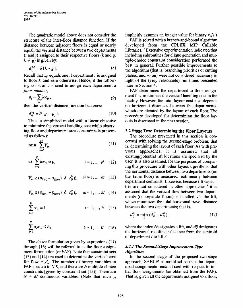
In SABLE, 6 a layout is specified by a sequence of department numbers with dividers to designate the floors. For example, in a 12-department, three- floor facility, the sequence 4 - -1 - -7 - -12- -10 / 8- - 6--11 / 5 - -3 - -9 - -2 indicates that departments 1, 4, 7, 10, and 12 have been assigned to the first floor; departments 6, 8, and 11 to the second floor; and so on. Given such a sequence (that is, a layout vector), the layout of each floor can be quickly constructed by using a spacefilling curve to map the layout vector to a floor layout) (See Bozer, Meller, and Erlebacher 3 for spacefilling curve gen- eration.) For example, with the spacefilling curve shown in Figure la, for the first floor one would obtain the layout shown in Figure lb. The number of grids assigned to each department in Figure lb is determined by the departmental area require- ments, which are specified by the user, while the location of each department is determined by the path of the spacefilling curve.
Given such a layout representation, revised (that is, "candidate") layouts can be generated by generating
V Start
n u l l n n l n n n l - - i n ln l l l I I ! I
(a) Spacefilling curve
I End
4 n _ . _ . , . !
4 ' 4 I 4 ] 4 • 7 I 7 I 12 12
ilIB R R I B R BUm u u n u I n Hi
(b) 4---1 - - 7 - - 1 2 - - 1 0
Figure 1 Constructing a Layout with a Layout Vector
new layout vectors (for example, 7--10--12---4-- 1 / 6--8--11 / 9--3--5--2) . In SABLE, a random address, al (0 < ai < 1), is assigned to each depart- ment i. To generate a candidate layout vector, a new address [distributed uniformly over (0,1)] is sampled for each department, and the departments are sorted according to their new addresses. (Actually, a new address is sampled for a depart- ment only with a certain probability, [3, which is typically set equal to approximately 0.10.) The divider locations for the candidate layout vector are determined simply by assigning each depart- ment, one at a time, as they appear in the layout vector, to the first floor until the first floor is not able to accommodate the next department in the layout vector. At that point, the next department is placed on the second floor and the process is con- tinued with the remaining departments in the lay- out vector. If available space on the last floor is insufficient, the candidate vector is declared infea- sible and the above procedure is repeated with "new" department addresses.
197
Journal of Manufacturing Systems Vol. 16/'No. 3 1997
The above procedure is modified by adding Yt to each department's address, where yi = 1 for the first-floor departments, y~ = 2 for the second-floor departments, and so on, to maintain the same department-to-floor assignment for each depart- ment while allowing the sequence of departments to change within each floor.
The reader is referred to Meller and Bozer 6 for other algorithm parameters and details regarding the annealing schedule.
3.3 Improved Two-Stage Approach Summary The improved two-stage approach, henceforth
referred to as STAGES, proceeds as follows: in stage one FAF and the solution procedure described in Section 3.1.2 are used to determine the permanent department-to-floor assignments, and in stage two the modified version of SABLE described in Section 3.2.1 is used to develop the floor layouts.
4. Numerical Evaluation In this section, various test problems are used to
compare STAGES with two other approaches, namely, SABLE and FLEX. SABLE6 is a single- stage algorithm that starts from a randomly gener- ated initial layout (with no permanent department- to-floor assignments) and attempts to improve it using spacefilling curves and simulated annealing. Based on the results presented in Meller and Bozer,6 SABLE outperforms MULTIPLE. (Furthermore, in Bozer, Meller, and Erlebacher3 it is shown that MULTIPLE is superior to SPACE- CRAFT, the other single-stage approach in the lit- erature.) That is, SABLE is the most competitive single-stage approach in multi-floor facility lay- out. The second approach, FLEX, is obtained as a simple combination of SABLE and STAGES; it is presented here for comparison purposes only. More specifically, FLEX is a two-stage approach where the first stage is identical to STAGES; how- ever, in the second stage (that is, when SABLE is applied) the department-to-floor assignments are allowed to vary. In other words, FLEX works like SABLE, but FLEX starts from the initial solution obtained by applying the first stage of STAGES.
Hence, comparing STAGES with SABLE will indicate whether or not, under comparable run times, a two-stage approach compares favorably
with a single-stage approach, that is, indicating whether or not the computational effort invested in obtaining an initial department-to-floor assign- ment (that minimizes the vertical handling cost) is justified. Comparing STAGES and FLEX will indicate what is gained or lost when the depart- ment-to-floor assignment obtained in stage one is allowed to vary in stage two.
To compare the above three algorithms (STAGES, SABLE, and FLEX), the test problems presented in Meller and Bozer 6 are used. (The data sets are referenced by the number of departments, the number of floors, and an index to further dif- ferentiate similar data sets; for example, 21 - -4 - - 3 represents the third data set with 21 departments and four floors. Data set 40 contains three lifts, while all others contain two.) The control parame- ters for SABLE and the modified version of SABLE were taken from Meller and Bozer. 6
The performance of the two-stage approach described here depends on the unit cost of vertical versus horizontal travel. As part of the experiment, it is initially assumed that the ratio of vertical to horizontal unit-handling costs (that is, the ratio of c v to c n, or the "V/H ratio") is equal to 5:1, which is the same ratio used in Meller and Bozer. 6 In sub- sequent experiments, alternative V/H ratios are explored, and the impact of a "low" ratio (1:1) as well as a "high" ratio (20:1) is evaluated. In most manufacturing applications, one would not expect the above ratio to be less than 1:1.
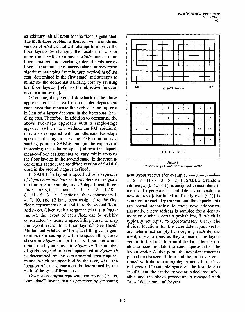
Another important factor in this comparison is the computational effort required by the three algorithms. To make a fair comparison, the same computational effort was maintained for each algorithm. For this purpose, STAGES and FLEX were run for each data set, and the run times (in CPU seconds) on a SUN SPARCstation IPX work- station were recorded. The results are shown in Table 1. (Because the STAGES run times were approximately equal to the FLEX run times, but never longer, the run times for these two algo- rithms are presented as "STAGES/FLEX.") Also presented in Table 1 is the average SABLE run time (of 10 runs), as presented in Meller and Bozel ~ (which were obtained on the same worksta- tion). Note from Table 1 that the STAGES/FLEX run times are between 0.5 and 2.5 times as long as the SABLE run times depending on the data set.
198
Journal of Manufacturing Systems Vol. 16/No. 3
1997
Table 1 Comparison of STAGES, FLEX, and SABLE Run Times (CPU seconds)
Data Set 11-2-1 11-2-2 12-3 21-4-1 21-4-2 21-4-3 21-4-4 40-4
Stage 1 Rtime 0.30 0.38 0.65 68.90 7.60 85.30 4.80 250.05
Stage 2 Rtime 0.90 1.06 0.90 9.54 7.77 11.07 7.51 26.75
STAGES/FLEX Total Rtime 1.20 1.44 1.55 78.44 15.37 96.37 12.31 276.80
SABLE average Rtime 2.45 2.01 2.86 38.60 35.24 38.34 26.35 305.26
Because the solution time for STAGES may be approximately 2.5 times as long as that of SABLE, the following conservative approach was taken. SABLE was run five times--with a different initial layout each t ime--to ensure that STAGES always uses the least computational resources. (Running SABLE several times with different starting solu- tions, as opposed to making one long run, is the rec- ommended approach when using a simulated- annealing-based search with a fixed amount of computational resources (Johnson et al., 16 p. 874).
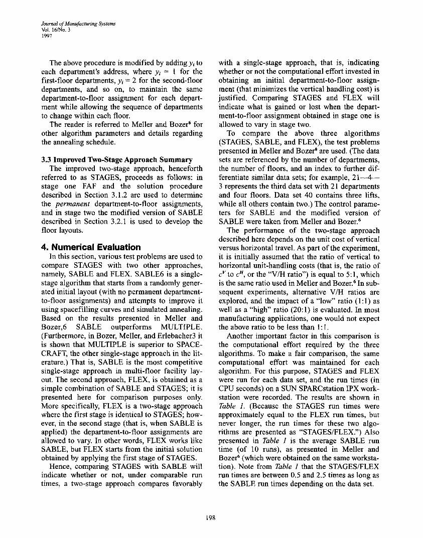
The objective function values, that is, the layout "costs," obtained with the three algorithms (by using the above run-time equalization scheme) are presented in Table 2 for a V/H ratio of 5:1. Note that, in Table 2, the minimum and maximum solution values (out of five solutions) obtained with SABLE are reported. Observe that, although a very conservative approach (in favor of SABLE) was taken in "equalizing" the run times, in seven out of the eight data sets shown in Table 2 STAGES obtains a layout cost that is less than or equal to the minimum layout cost obtained by SABLE. In com- paring STAGES and FLEX, on the other hand, it is
Table 2 Layout Cost Comparison of the Approaches with
Equalized Run Times
observed that STAGES obtains lower-cost solutions in six of the eight cases and equal or worse solu- tions in the other two cases. Hence, for a V/H ratio of 5:1, it is concluded that STAGES outperforms both SABLE and FLEX.
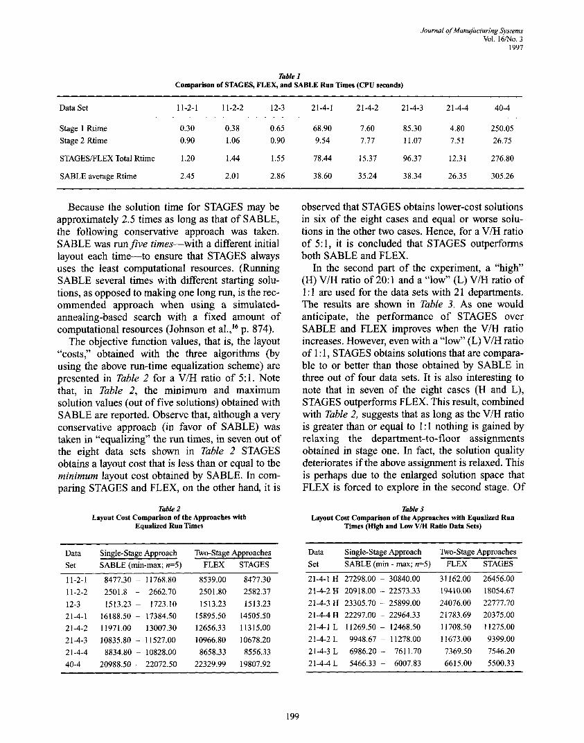
In the second part of the experiment, a "high" (H) V/H ratio of 20:1 and a "low" (L) V/H ratio of 1:1 are used for the data sets with 21 departments. The results are shown in Table 3. As one would anticipate, the performance of STAGES over SABLE and FLEX improves when the V/H ratio increases. However, even with a "low" (L) V/H ratio of 1 : 1, STAGES obtains solutions that are compara- ble to or better than those obtained by SABLE in three out of four data sets. It is also interesting to note that in seven of the eight cases (H and L), STAGES outperforms FLEX. This result, combined with Table 2, suggests that as long as the V/H ratio is greater than or equal to 1:1 nothing is gained by relaxing the department-to-floor assignments obtained in stage one. In fact, the solution quality deteriorates if the above assignment is relaxed. This is perhaps due to the enlarged solution space that FLEX is forced to explore in the second stage. Of
Table 3 Layout Cost Comparison of the Approaches with Equalized Run
Times (High and Low V/H Ratio Data Sets)
Data
Set
Single-Stage Approach Two-Stage Approaches
SABLE (min-max; n=5) FLEX STAGES
11-2-1 8477.30 - 11768.80 8539.00 8477.30
11-2-2 2501.8 - 2662.70 2501.80 2582.37
12-3 1513.23 - 1723.10 1513.23 1513.23
21-4-1 16188.50 - 17384.50 15895.50 14505.50
21-4-2 11971.00 - 13007.30 12656.33 11315.00
21-4-3 10835.80 - 11527.00 10966.80 10678.20
21-4-4 8834.80 - 10828.00 8658.33 8556.33
40-4 20988.50 - 22072.50 22329.99 19807.92
Data
Set
Single-Stage Approach Two-Stage Approaches
SABLE (min - max; n=5) FLEX STAGES
21-4-1H 27298.00 - 30840.00 31162.00 26456.00
21-4-2H 20918.00 - 22573.33 19410.00 18054.67
21-4-3H 23305.70 - 25899.00 24076.00 22777.70
21-4-4H 22297.00 - 22964.33 21783.69 20375.00
21-4-1L 11269.50 - 12468.50 11708.50 11275.00
21-4-2 L 9948.67 - 11278.00 11673.00 9399.00
21-4-3 L 6986.20 - 7611.70 7369.50 7546.20
21-4-4 L 5466.33 - 6007.83 6615.00 5500.33
199
Journal of Manufacturing Systems Vol. 16/No. 3 1997
course, the above conclusions are based on using the "same" simulated-annealing algorithm to improve the floor layouts in the second stage.
Overall, it is concluded that the two-stage approach presented here (STAGES) seems to out- perform the single-stage approach (SABLE) as well as an alternative (and seemingly more flexible) two- stage approach (FLEX). It is believed that such results justify the computational effort expended in stage one and provide more reason to use the two- stage approach presented here as long as the unit vertical handling cost is greater than or equal to the unit horizontal handling cost, which is very likely to hold true in many manufacturing applications. It is also believed that the two-stage approach has man- agerial appeal because it attempts to place depart- ments with high interaction on the same floor before it tries to develop a layout for each floor.
It is interesting to consider that with unlimited run time, one would expect both SABLE and FLEX to outperform STAGES because STAGES, due to stage one, restricts the solution space. However, the results presented here indicate that restricting the solution space works in favor of STAGES because this restriction is not arbitrary. That is, STAGES concentrates its (computational) resources in a "good" area of the solution space. Finally, note that the linear model presented in Section 3.1.2 was instrumental in determining optimal solutions in stage one with reasonable run times.
5. "Real-World" Application of the Improved Two-Stage Approach
In this section, STAGES is used to illustrate the solution it obtained from data that were driven by the authors' involvement in a major multi-floor manufacturing facility layout project. (Of course, the data presented here is not the confidential data supplied as part of the project.) The company pro- duces five different types of incandescent light bulbs in a three-floor facility that encompasses
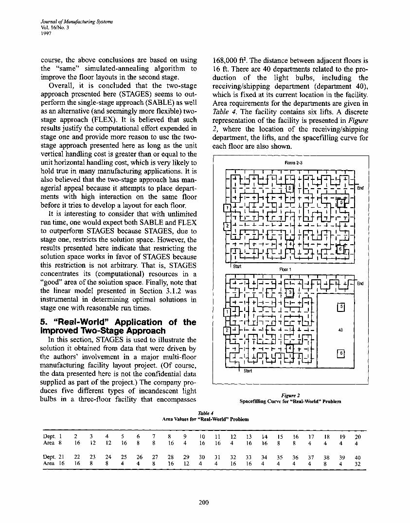
168,000 ft 2. The distance between adjacent floors is 16 ft. There are 40 departments related to the pro- duction of the light bulbs, including the receiving/shipping department (department 40), which is fixed at its current location in the facility. Area requirements for the departments are given in Table 4. The facility contains six lifts. A discrete representation of the facility is presented in Figure 2, where the location of the receiving/shipping department, the lifts, and the spacefilling curve for each floor are also shown.
Floors 2-3
I I ~ I ~ I L..=..~nd T 7z_- F q -F T - flz_-,ed- i T i---I--i ii ~ -
, , -
' ' 7 4 r , r, n_n_~ r - l . ~ ~-_.~- I~l-I --I-- -I- --I -- I- a - I- .I- --I - I- -~ _ l-I..I. -
T I Star
Floor 1
End
Figure 2 Spacef'llling Curve for "Real-World" Problem
Table 4 Area Values for "Real-World" Problem
Dept. 1 2 3 4 5 6 7 8 9 10 11 12 13 14 15 16 17 18 19 20 Area 8 16 12 12 16 8 8 16 4 16 16 4 16 16 8 8 4 4 4 4
Dept. 21 22 23 24 25 26 27 28 29 30 31 32 33 34 35 36 37 38 39 40 Area 16 16 8 8 4 4 8 16 12 4 4 16 16 4 4 4 4 8 4 32
200
Journal of Manufacturing Systems Vol, 16/'No. 3
1997
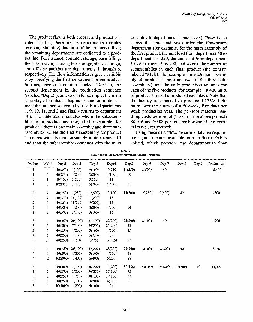
The product flow is both process and product ori- ented. That is, there are six departments (besides receiving/shipping) that most of the products utilize; the remaining departments are dedicated to a prod- uct line. For instance, common storage, base-filling, the base freezer, packing box storage, sleeve storage, and off-line packing are departments 1 through 6, respectively. The flow information is given in Table 5 by specifying the first department in the produc- tion sequence (the column labeled "Deptl"), the second department in the production sequence (labeled "Dept2"), and so on (for example, the main assembly of product 1 begins production in depart- ment 40 and then sequentially travels to departments 1, 9, 10, 11, and 2 and finally returns to department 40). The table also illustrates where the subassem- blies of a product are merged (for example, for product 1 there is one main assembly and three sub- assemblies, where the first subassembly for product 1 merges with its main assembly in department 10 and then the subassembly continues with the main
assembly to department 11, and so on). Table 5 also shows the unit load sizes a~er the flow-origin department (for example, for the main assembly of the first product, the unit load from depaitment 40 to department 1 is 250; the unit load from department 1 to department 9 is 100, and so on), the number of subassemblies in each final product (the column labeled "Multi," for example, for each main assem- bly of product 1 there are two of the third sub- assemblies), and the daily production volumes for each of the five products (for example, 18,400 units of product 1 must be produced each day). Note that the facility is expected to produce 12.36M light bulbs over the course of a 50-week, five days per week production year. The per-foot material han- dling costs were set at (based on the above project) $0.016 and $0.08 per foot for horizontal and verti- cal travel, respectively.
Using these data (flow, departmental area require- ments, and the area available on each floor), FAF is solved, which provides the department-to-floor
Table 5 Flow Matrix Generator for "Real-World" Problem
Product Multl Deptl Dept2 Dept3 Dept4 Dept5 Dept6 Dept7 D e p t 8 D e p t 9 Production
1 1 40(250) 1(100) 9 (100 ) 10(250) 11(250) 2(500) 40 18,400 1 1 40(250) 1(200) 3 (200 ) 4(100) 10 1 1 40(100) l(200) 5(100) 11 1 2 40(2000) 1(400) 5 (200 ) 6(400) 11
2 1 40(250) 1(250) 12(500) 13(100) 14(200) 15(250) 2(500) 40 4600 2 1 40(250) 16(100) 17(200) 13 2 1 40(250) 18(200) 19(200) 13 2 1 40(500) 1(200) 3 (200 ) 4(200) 14 2 1 40(500) 1(100) 5(100) 15
3 1 40(250) 20(100) 21(100) 22(200) 23(200) 8(100) 40 6900 3 1 40(200) 7(100) 24(200) 25(200) 22 3 1 40(250) 1(200) 3 ( 1 0 0 ) 4(200) 25 3 l 40(250) 1(100) 5(250) 23 3 0.5 40(250) 1(50) 5(25) 6(62.5) 23
4 1 40(250) 26(100) 27(200) 28(200) 29(200) 8 (100) 2(200) 40 8050 4 1 40(200) 1(200) 3 (100 ) 4(100) 28 4 2 40(2000) 1(400) 5 (400 ) 6(200) 29
5 1 40(500) 1(100) 30(200) 31(200) 32(100) 33(100) 34(200) 2(500) 40 11,500 5 1 40(200) 1(200) 36(250) 37(100) 32 5 1 40(250) 1(250) 38(100) 39(100) 33 5 1 40(250) 1(100) 3 (200 ) 4(100) 33 5 1 40(1000) 1(200) 5(100) 34
201
Journal of Manufacturing Systems Vol. 16/No. 3 1997
Table 6 Department-to-Floor Assignment for "Real-World" Problem
Floor Depts. Assigned to Floor
1 1, 3, 4, 9, 10, 12, 28, 30, 31, 32, 33, 36, 37, 38, 39, 40
2 2, 5, 6, 7, 8, 11, 15, 23, 24, 25, 26, 27, 29, 34, 35
3 13, 14, 16, 17, 18, 19, 20, 21, 22
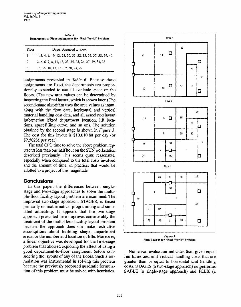
assignments presented in Table 6. Because these assignments are fixed, the departments are propor- tionally expanded to use all available space on the floors. (The new area values can be determined by inspecting the final layout, which is shown later.) The second-stage algorithm uses the area values as input, along with the flow data, horizontal and vertical material handling cost data, and all associated layout information (fixed department location, lift loca- tions, spacefilling curve, and so on). The solution obtained by the second stage is shown in Figure 3. The cost for this layout is $10,010.80 per day (or $2.502M per year).
The total CPU time to solve the above problem rep- resents less than one half hour on the SUN workstation described previously. This seems quite reasonable, especially when compared to the total costs involved and the amount of time, in practice, that would be allotted to a project of this magnitude.
C o n c l u s i o n s In this paper, the differences between single-
stage and two-stage approaches to solve the multi- ple-floor facility layout problem are examined. The improved two-stage approach, STAGES, is based primarily on mathematical programming and simu- lated annealing. It appears that the two-stage approach presented here improves considerably the treatment of the multi-floor facility layout problem because the approach does not make restrictive assumptions about building shape, department areas, or the number and location of lifts. Moreover, a linear objective was developed for the first-stage problem that allowed exploring the affect of using a good department-to-floor assignment before con- sidering the layouts of any of the floors. Such a for- mulation was instrumental in solving this problem because the previously proposed quadratic formula- tion of this problem must be solved with heuristics.
Floor 3
13
19
14 []
E! 18
Floor 2
, =
22
17
[]
20
21
16
D
[
11
23
24
[]
34
13 25
15
26
i ,
29 35
i i
27
[]
[]
Floor 1
r 10
33
9 37
12 36
39
32
38
1.=1
31 30
28
[]
40
[]
Figure 3 Final Layout for "Real-World" Problem
Numerical evaluation indicates that, given equal run times and unit vertical handling costs that are greater than or equal to horizontal unit handling costs, STAGES (a two-stage approach) outperforms SABLE (a single-stage approach) and FLEX (a
202
Journal of Manufacturing Systems Vol. 16/No. 3
1997
related two-stage approach). That is, reducing the solution space by solving the problem in two stages as described here appears to be effective and justi- fied as long as in the second stage the floor layouts are determined concurrently and the department-to- floor assignments remain fixed. A "real-world" example problem was included to illustrate the improved approach on a problem derived from practical experience.
Acknowledgments This study was partially supported by Dr. Meller's
NSF grant no. DMII-9412646 and the Russell Corp. under Auburn University Administrative Digest nos. 1222-94CG and 878-95CG. The study was also par- tially supported by Dr. Bozer's PYI Award under NSF grant no. DDM-8858562 and the Center for Display Technology and Manufacturing at the University of Michigan. All data available on request from the first author.
References 1. M.R. Garey and D.S. Johnson, Computers and Intractability: A Guide
to the Theory ofNP-Completeness (NewYork: W.H. Freeman and Co., 1979). 2. A. Kusiak and S.S. Heragn, "The Facility Layout Problem" European
Journal of Operational Research (v29, 1987), pp229-251. 3. Y.A. Bozer, R.D. Meller, and S.J. Erlebacher, "An Improvement-Type
Layout Algorithm for Single and Multiple Floor Facilities" Management Science (v40, n7, 1994), pp918-932.
4. B. Montreuil, "A Modelling Framework for Integrating Layout Design and Flow Network Design," Proceedings from the Material Handing Research Colloquium (Hebron, KY) (1990), pp43-58.
5. R.V. Johnson, "SPACECRAFT for Multi-Floor Layout Planning," Management Science (v28, 1982), pp407-417.
6. R.D. Meller and Y.A. Bozer, "A New Simulated Annealing Algorithm for the Facility Layout Problem," International Journal of Production Research (v34, n6, 1996), pp1675-1692.
7. G.E. Armour and E.S. Buffa, "A Heuristic Algorithm and Simulation Approach to Relative Location of Facilities," Management Science (v9, 1963), pp294-309.
8. J.M. Seehof and W.O. Evans, "Automated Layout Design Program," Journal of Industrial Engineering (v 18, 1967), pp690-695.
9. C.E. Donaghey and V.E Pire, "Solving the Facility Layout Problem with BLOCPLAN" (Houston, TX: Industrial Engg. Dept., Univ. of Houston, 1990). 10. V. Pire, "Automated Multistory Layout System," Master's thesis (Houston, TX: Industrial Engg. Dept., Univ. of Houston, Dec. 1989). 11. R.S. Liggett and WJ. Mitchell, "Optimal Space Planning in Practice," Computer Aided Design (v 13, 1981 ), pp277-288. 12. G.W. Graves and A.B. Whinston, "An Algorithm for the Quadratic Assignment Problem," Management Science (v17, 1982), pp453-471. 13. B.K. Kaku, G.L. Thompson, and I. Baybars, "A Heuristic Method for the Multi-Story Layout Problem," European Journal of Operational Research (v37, 1988), pp384-397. 14. R.L. Francis, L.E McGinnis, Jr., and J.A. White, Facility Layout and Location: An Analytical Approach (Englewood Cliffs, NJ: Prentice-Hall, 1992). 15. "Using the CPLEX Mixed-Integer Library," Version 3.0 (Incline Village, NV: CPLEX Optimization, Inc., 1993). 16. D.S. Johnson, C.R. Aragon, L.A. McGeoch, and C. Schevon, "Optimization by Simulated Annealing: An Experimental Evaluation; Part I, Graph Partitioning," Operations Research (v37, 1989), pp865-892.
Authors' Biographies Yavuz A. Bozer received his BSIE degree from METU in Turkey and
his MS and PhD in industrial and systems engineering from Georgia Institute of Technology. He received the 1987 IIE Dissertation Award for his work concerned with the efficient design and operation of order-picking systems. In 1988 he was selected as a Presidential Young Investigator by the National Science Foundation. Dr. Bozer's professional experience includes his full-time employment with the SysteCon Div. of Coopers & Lybrand and, subsequently, his employment with the Material Handling Research Center at Georgia Tech as a full-time research engineer. Currently, he is an associate professor in the Department of Industrial and Operations Engineering at the University of Michigan. His teaching and research inter- ests focus on the efficient design and operation of material flow and stor- age systems, material handling, and facilities layout. He is a member of IIE and INFORMS.
Russell D. Meller received his BSE, MSE, and PhD in industrial and operations engineering from the University of Michigan. His dissertation on facility layout was awarded the 1994 Institute of Industrial Engineers Outstanding Dissertation Award and First Prize in the 1993 College on Location Analysis Dissertation Prize Competition from The Institute of Management Sciences. In 1996 he received a CAREER Development Grant from the National Science Foundation. Dr. Meller's professional experience includes consulting with the SysteCon Div. of Coopers & Lybrand, General Electric, and the Russell Corp. Currently, he is an assis- tant professor of industrial and systems engineering at Auburn University. His research interests include facilities layout, automated material handling systems, and operations research applications in forestry. He is a member of lIE, INFORMS, and Alpha Pi Mu.
203