Embed Size (px)
Citation preview
1
Alternating Current Circuits
Chapter 33
2
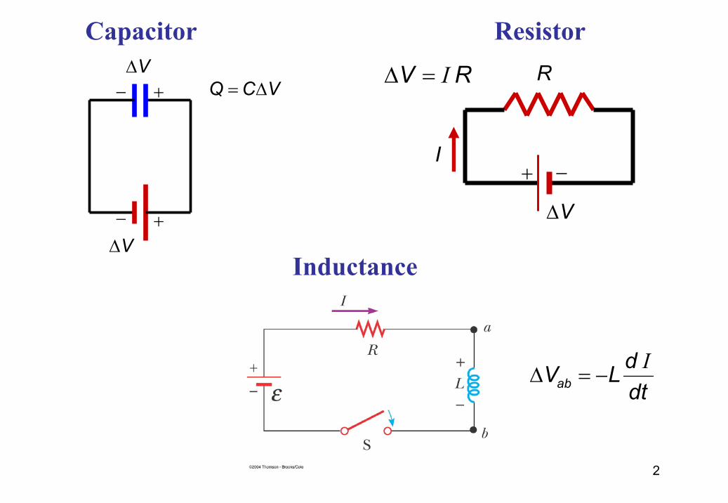
Inductance
I∆ = −ab
dV Ldt
+−
+−
V∆
V∆Q C V= ∆
Capacitor R
V∆
+ −I
Resistor I∆ =V R
3
AC power source
The AC power source provides an alternative voltage, Notation- Lower case symbols will indicate instantaneous values- Capital letters will indicate fixed values
∆ (t)v
• The output of an AC power source is sinusoidal ∆v = ∆Vmax sin ωt
• ∆v is the instantaneous voltage• ∆Vmax is the maximum output voltage of the source• ω is the angular frequency of the AC voltage
4
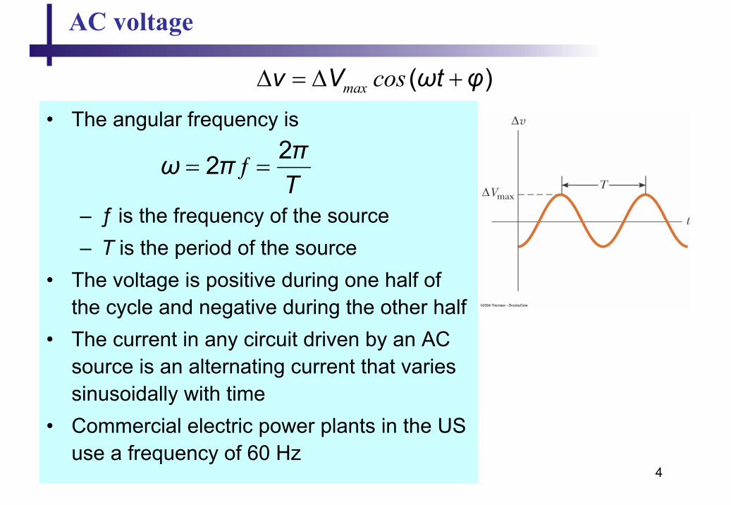
AC voltage
• The angular frequency is
– ƒ is the frequency of the source– T is the period of the source
• The voltage is positive during one half of the cycle and negative during the other half
• The current in any circuit driven by an AC source is an alternating current that varies sinusoidally with time
• Commercial electric power plants in the US use a frequency of 60 Hz
22 ƒ πω πT
= =
max cos∆ = ∆ +( )v V ωt φ
5
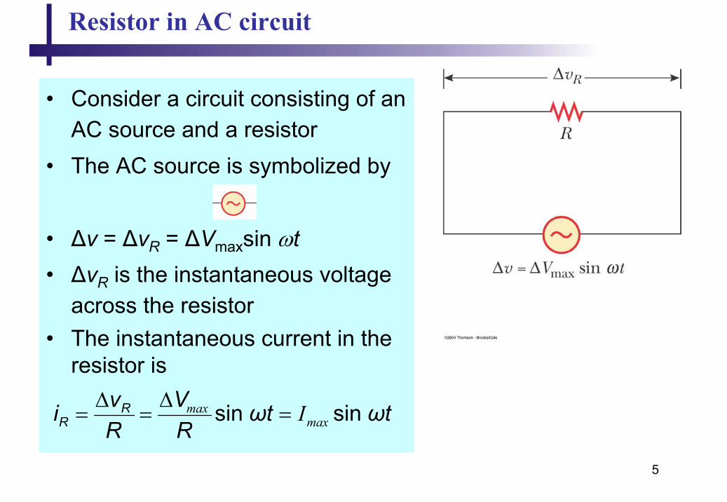
Resistor in AC circuit
• Consider a circuit consisting of an AC source and a resistor
• The AC source is symbolized by
• ∆v = ∆vR = ∆Vmaxsin ωt• ∆vR is the instantaneous voltage
across the resistor• The instantaneous current in the
resistor is
sin sin maxmaxIR
Rv Vi ωt ωtR R
∆ ∆= = =
6
Resistor in AC circuit
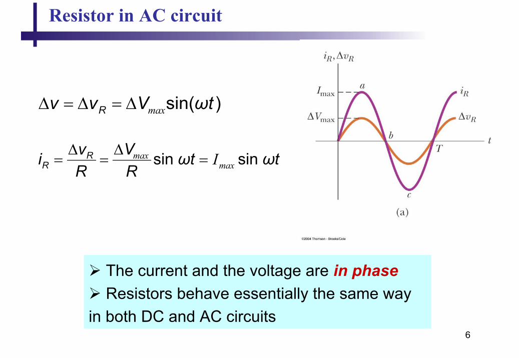
max∆ = ∆ = ∆ sin( )Rv v V ωt
sin sin maxmaxIR
Rv Vi ωt ωtR R
∆ ∆= = =
The current and the voltage are in phaseResistors behave essentially the same way
in both DC and AC circuits
7
Resistor in AC circuit: Phasor diagram
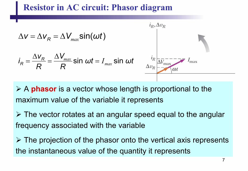
max∆ = ∆ = ∆ sin( )Rv v V ωt
sin sin maxmaxIR
Rv Vi ωt ωtR R
∆ ∆= = =
A phasor is a vector whose length is proportional to the maximum value of the variable it represents
The vector rotates at an angular speed equal to the angular frequency associated with the variable
The projection of the phasor onto the vertical axis represents the instantaneous value of the quantity it represents
8
rms current and voltage
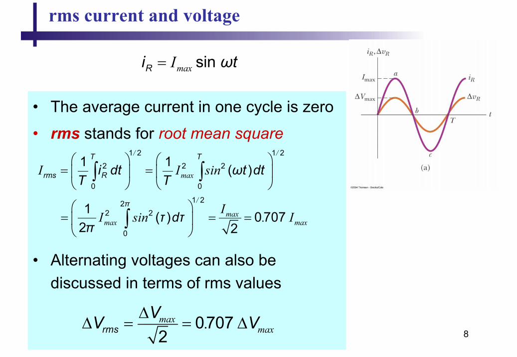
maxI= sin Ri ωt
• The average current in one cycle is zero
• rms stands for root mean square
• Alternating voltages can also be discussed in terms of rms values
/ /
max
/
maxmax max
I I sin
II sin . I
= =
= = =
∫ ∫
∫
1 2 1 2
2 2 2
0 0
1 222 2
0
1 1 ( )
1 ( ) 07072 2
T T
rms R
π
i dt ωt dtT T
τ dτπ
07072max
max.rmsVV V∆
∆ = = ∆
9
rms current and voltage: power
• The rate at which electrical energy is dissipated in the circuit is given by
P = i 2 R
• where i is the instantaneous current
• The average power delivered to a resistor that carries an alternating current is
2Iav rmsP R=
10
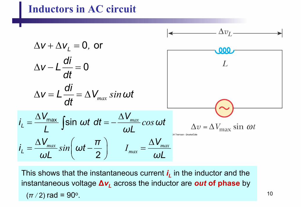
Inductors in AC circuit
0 or
0
max
,
sin
Lv vdiv Ldtdiv L V ωtdt
∆ + ∆ =
∆ − =
∆ = = ∆
max
max maxmax
cos
sin I
∆ ∆= = −
∆ ∆ = − =
∫max sin
2
L
L
V Vi ωt dt ωtL ωL
V Vπi ωtωL ωL
This shows that the instantaneous current iL in the inductor and the instantaneous voltage ∆vL across the inductor are out of phase by
rad = 90o./( 2)π
11
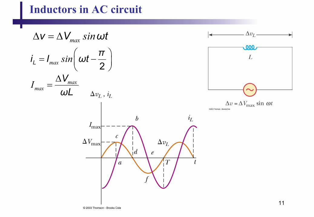
Inductors in AC circuit
max sin∆ = ∆v V ωt
max sin = − 2L
πi I ωt
maxmaxI ∆
=VωL
12
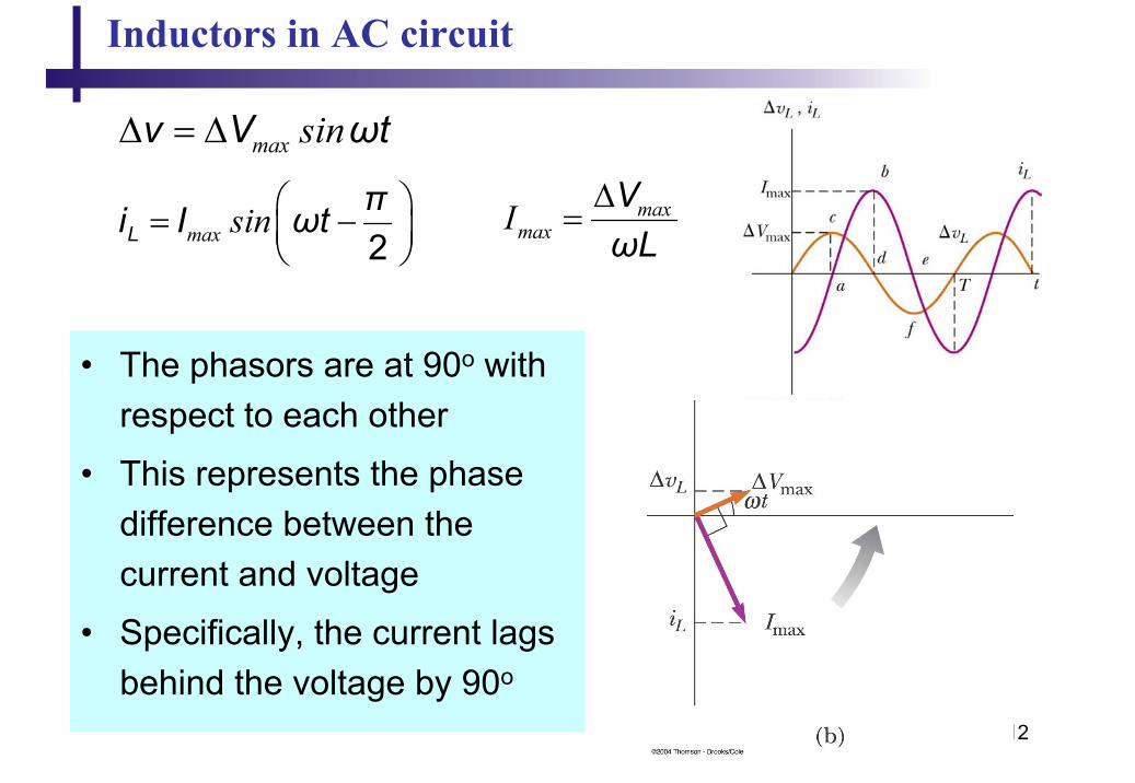
Inductors in AC circuit
max sin∆ = ∆v V ωt
max sin = − 2L
πi I ωt maxmaxI ∆
=VωL
• The phasors are at 90o with respect to each other
• This represents the phase difference between the current and voltage
• Specifically, the current lags behind the voltage by 90o

13
Inductors in AC circuit
max sin∆ = ∆v V ωt
max sin = − 2L
πi I ωt maxmaxI ∆
=VωL
• The factor ωL has the same units as resistance and is related to current and voltage in the same way as resistance
• The factor is the inductive reactance and is given by:XL = ωL
– As the frequency increases, the inductive reactance increases
maxmaxI
L
VX
∆=

14
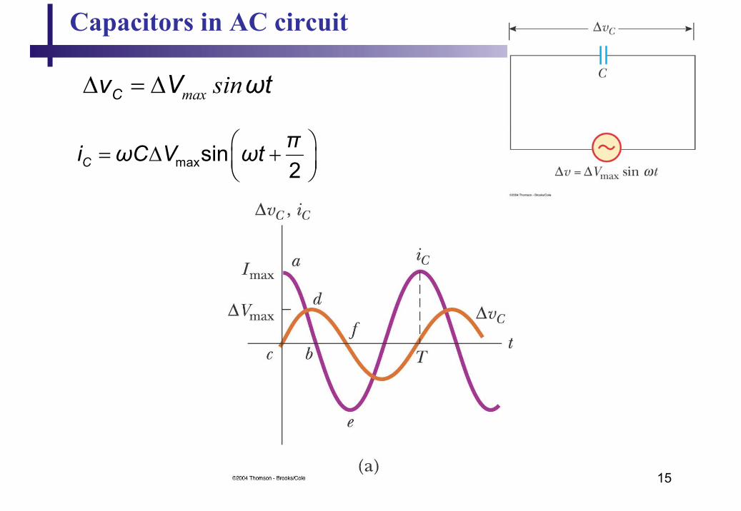
Capacitors in AC circuit
∆v + ∆vc = 0 and so ∆v = ∆vC = ∆Vmax sin ωt
– ∆vc is the instantaneous voltage across the capacitor
• The charge is
q = C∆vC =C∆Vmax sin ωt
• The instantaneous current is given by
• The current is (π/2) rad = 90o out of phase with the voltage
= = ∆
= ∆ +
max
max
cos
sin2
C
C
dqi ωC V ωtdt
πi ωC V ωt
15
Capacitors in AC circuit
= ∆ +
maxsin2Cπi ωC V ωt
max sin∆ = ∆Cv V ωt
16
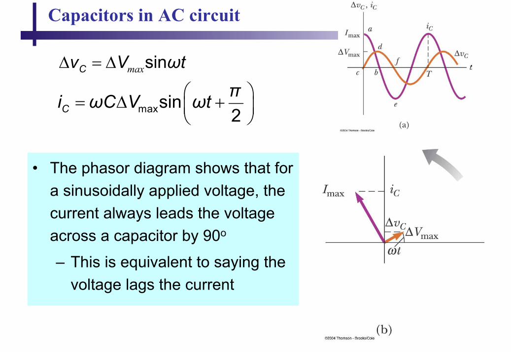
Capacitors in AC circuit
= ∆ +
maxsin2Cπi ωC V ωt
max∆ = ∆ sinCv V ωt
• The phasor diagram shows that for a sinusoidally applied voltage, the current always leads the voltage across a capacitor by 90o
– This is equivalent to saying the voltage lags the current

17
Capacitors in AC circuit
= ∆ +
maxsin2Cπi ωC V ωt
max∆ = ∆ sinCv V ωt
• The maximum current
• The impeding effect of a capacitor on the current in an AC circuit is called the capacitive reactance and is given by
maxmax
1 and ICC
VXωC X
∆≡ =
maxmax max (1 )I
/VωC VωC
∆= ∆ =
18
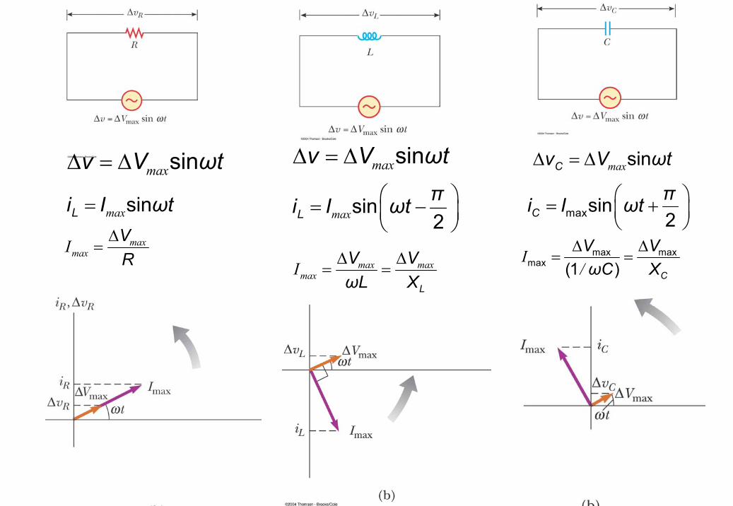
max∆ = ∆ sinv V ωt
max = −
sin2Lπi I ωt
max maxmaxI ∆ ∆
= =L
V VωL X
max∆ = ∆ sinv V ωt
max= sinLi I ωt
maxmaxI ∆
=VR
= +
maxsin2Cπi I ωt
max∆ = ∆ sinCv V ωt
I/
∆ ∆= =max max
max (1 ) C
V VωC X
19
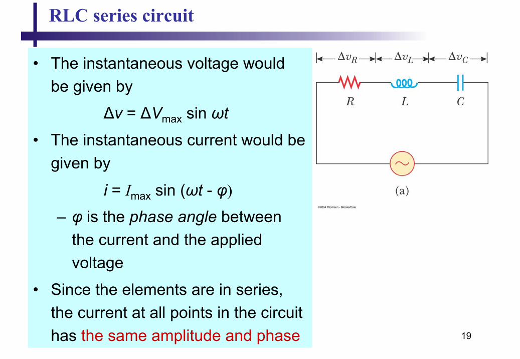
RLC series circuit
• The instantaneous voltage would be given by
∆v = ∆Vmax sin ωt
• The instantaneous current would be given by
i = Imax sin (ωt - φ)
– φ is the phase angle between the current and the applied voltage
• Since the elements are in series, the current at all points in the circuit has the same amplitude and phase
20
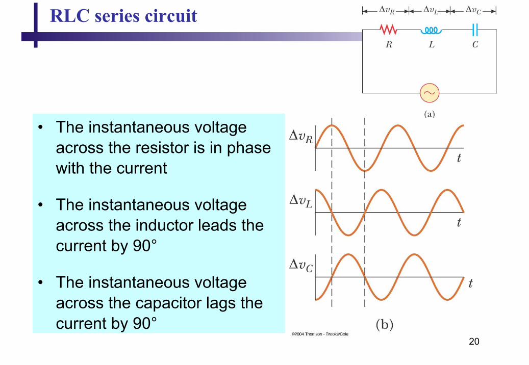
RLC series circuit
• The instantaneous voltage across the resistor is in phase with the current
• The instantaneous voltage across the inductor leads the current by 90°
• The instantaneous voltage across the capacitor lags the current by 90°
21
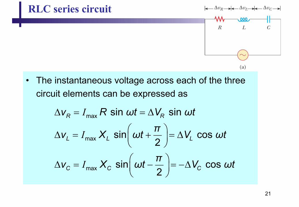
RLC series circuit
• The instantaneous voltage across each of the three circuit elements can be expressed as
max
max
max
sin sin
sin cos 2
sin cos 2
I
I
I
R R
L L L
C C C
v R ωt V ωtπv X ωt V ωt
πv X ωt V ωt
∆ = = ∆
∆ = + = ∆ ∆ = − = −∆
22
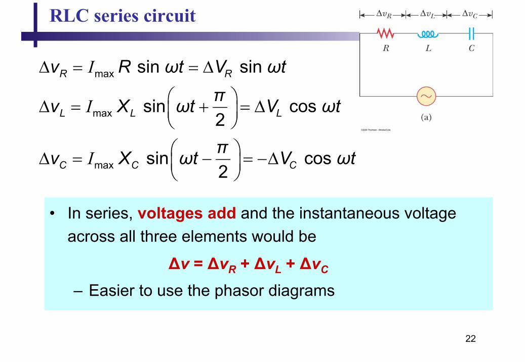
RLC series circuit
max
max
max
sin sin
sin cos 2
sin cos 2
I
I
I
R R
L L L
C C C
v R ωt V ωtπv X ωt V ωt
πv X ωt V ωt
∆ = = ∆
∆ = + = ∆ ∆ = − = −∆
• In series, voltages add and the instantaneous voltage across all three elements would be
∆v = ∆vR + ∆vL + ∆vC
– Easier to use the phasor diagrams
23
RLC series circuit
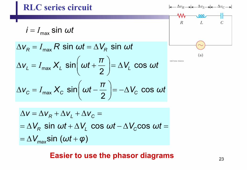
I= max sin i ωt
max
max
max
sin sin
sin cos 2
sin cos 2
I
I
I
R R
L L L
C C C
v R ωt V ωtπv X ωt V ωt
πv X ωt V ωt
∆ = = ∆
∆ = + = ∆ ∆ = − = −∆
∆ = ∆ + ∆ + ∆ =
= ∆ + ∆ − ∆ =
= ∆ +
sin cos cos sin ( )
R L C
R L C
max
v v v vV ωt V ωt V ωtV ωt φ
Easier to use the phasor diagrams

24
RLC series circuit
The phasors for the individual elements:
• The individual phasor diagrams can be combined
• Here a single phasor Imax is used to represent the current in each element– In series, the current is the same
in each element
25
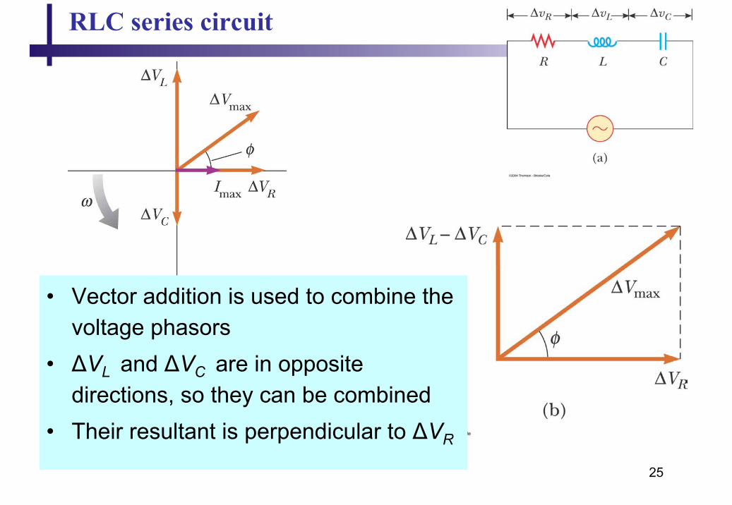
RLC series circuit
• Vector addition is used to combine the voltage phasors
• ∆VL and ∆VC are in opposite directions, so they can be combined
• Their resultant is perpendicular to ∆VR
26
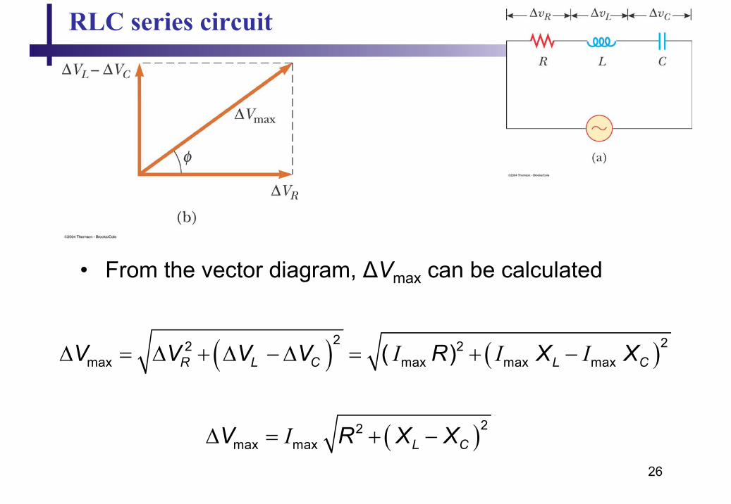
RLC series circuit
• From the vector diagram, ∆Vmax can be calculated
( ) ( )I I I∆ = ∆ + ∆ − ∆ = + −2 22 2
max max max max( )R L C L CV V V V R X X
( )I∆ = + − 22max max L CV R X X
27
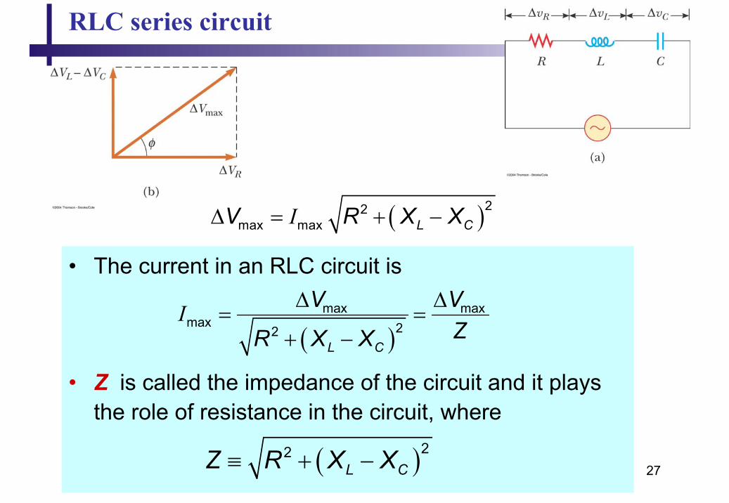
RLC series circuit
( )I∆ = + − 22max max L CV R X X
• The current in an RLC circuit is
• Z is called the impedance of the circuit and it plays the role of resistance in the circuit, where
( )max max
max 22I
L C
V VZR X X
∆ ∆= =
+ −
( )22L CZ R X X≡ + −

28
RLC series circuit
( )22L CZ R X X≡ + −
impedance triangle
I ∆= max
maxVZ
29
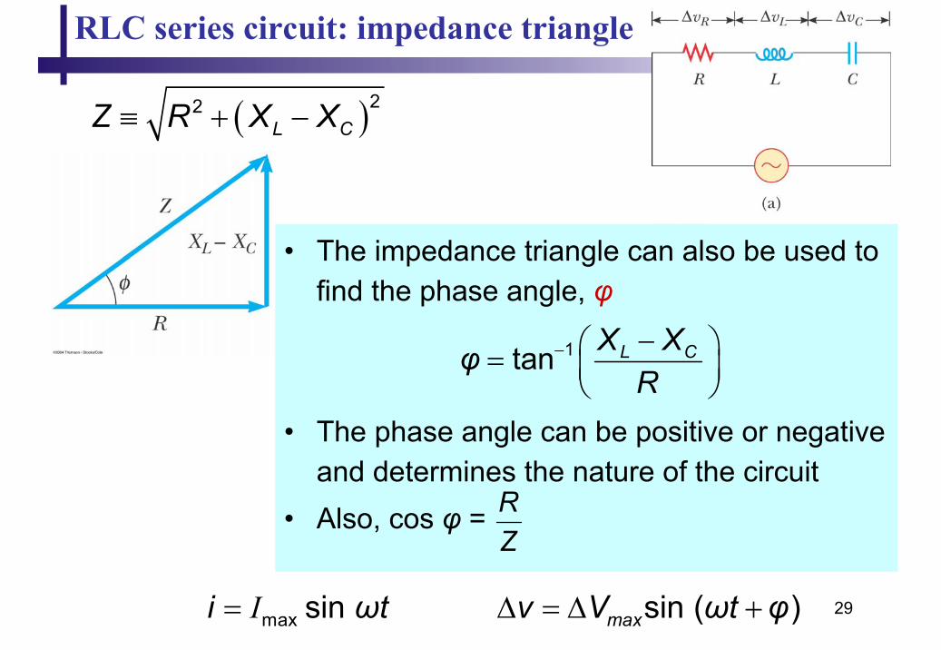
RLC series circuit: impedance triangle
( )22L CZ R X X≡ + −
• The impedance triangle can also be used to find the phase angle, φ
• The phase angle can be positive or negative and determines the nature of the circuit
• Also, cos φ =
1tan L CX XφR
− − =
RZ
I= max sin i ωt ∆ = ∆ +sin ( )maxv V ωt φ
30
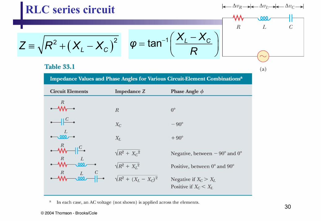
RLC series circuit
( )22L CZ R X X≡ + −
1tan L CX XφR
− − =

31
Power in AC circuit
• The average power delivered by the generator is converted to internal energy in the resistor– Pav = ½ Imax ∆Vmax cos φ = Irms∆Vrms cos φ– cos φ is called the power factor of the circuit
• We can also find the average power in terms of R
I ∆= max
maxVZ
( )max
maxI I ∆ ∆ = = = = + −
2 22 2 max
22
1 12 2 2av rms
L C
V V RP R R RZ R X X
II = maxrms 2
32
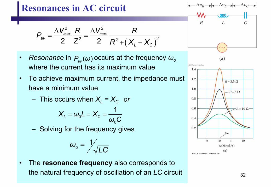
Resonances in AC circuit
• Resonance in occurs at the frequency ωo
where the current has its maximum value• To achieve maximum current, the impedance must
have a minimum value– This occurs when XL = XC or
– Solving for the frequency gives
• The resonance frequency also corresponds to the natural frequency of oscillation of an LC circuit
1oω LC
=
( )max max∆ ∆
= =+ −
2 2
22 22 2avL C
V VR RPZ R X X
= = =00
1L CX ω L X
ω C
( )avP ω
33
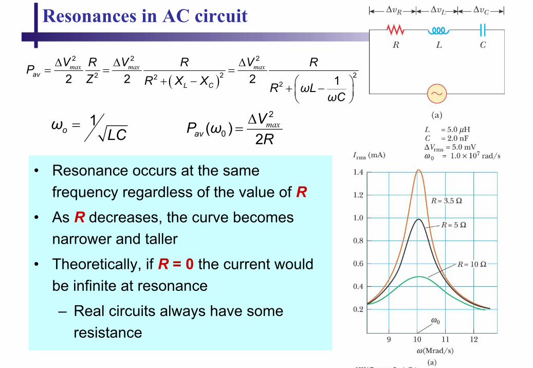
Resonances in AC circuit
1oω LC
=
( )max max max∆ ∆ ∆
= = =+ − + −
2 2 2
2 22 222 2 2 1
avL C
V V VR R RPZ R X X R ωL
ωC
• Resonance occurs at the same frequency regardless of the value of R
• As R decreases, the curve becomes narrower and taller
• Theoretically, if R = 0 the current would be infinite at resonance
– Real circuits always have some resistance
max∆=
2
0( )2avVP ωR