Embed Size (px)
Citation preview
The Pennsylvania State University
The Graduate School
College of Engineering
ALTERATIONS IN AMPUTEE GAIT MECHANICS PRODUCED BY VARIED
STIFFNESS AND DAMPING IN A SHOCK ABSORBING PROSTHETIC PYLON
A Thesis in
Mechanical Engineering
by
Anthony T. Ligouri
©2015 Anthony T. Ligouri
Submitted in Partial Fulfillment
of the Requirements
for the Degree of
Master of Science
August 2015
ii
The thesis of Anthony T. Ligouri was reviewed and approved* by the following:
Stephen J. Piazza
Professor of Kinesiology, Mechanical Engineering, and Orthopaedics & Rehabilitation
Thesis Advisor
H. Joseph Sommer III
Professor of Mechanical Engineering
Karen Thole
Professor of Mechanical Engineering
Department Head of Mechanical and Nuclear Engineering
*Signatures are on file in the Graduate School.
iii
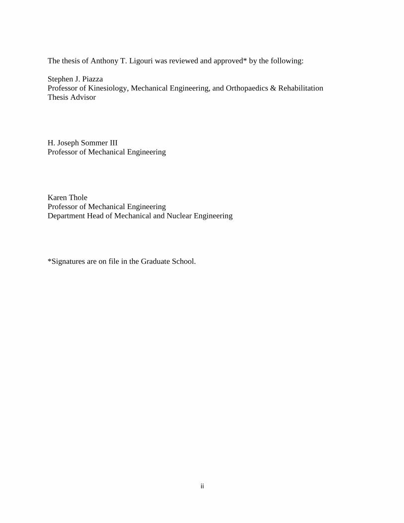
Abstract
Advanced electrically powered prostheses have become increasingly common in recent
years for use by amputees. Their power requirements are of considerable concern due to their
need for frequent charging and potential to cause problems if they lose power. Energy
harvesting from human locomotion has been studied by many researchers as a potential means to
meet these power requirements. The main purpose of this thesis is to investigate the effects of
varied stiffness and damping of a shock absorbing prosthetic pylon on unilateral, transtibial
amputee gait in an attempt to characterize the effects of a real energy harvesting prosthetic pylon.
We investigated the variations in intact side ankle moment and power and intact side hip
moment and power of five unilateral, transtibial amputees walking with a shock absorbing pylon
across five different stiffness and damping combinations. We also conducted a computational
modeling study in which we simulated a unilateral, transtibial amputee walking with a shock
absorbing pylon with 30 different combinations of stiffness and damping and investigated the
differences in intact side ankle moment and power, knee moment and power, hip moment and
power, and center of mass acceleration.
Variation of both stiffness and damping had significant effects on intact side joint
kinetics, but not all subjects reacted in the same way to increasing stiffness and damping. In
general, a more compliant pylon allowed amputees to walk with reduced joint moments and
powers. Modeling results suggested that some combinations of stiffness and damping can
minimize user effort while still effectively harvesting energy. This thesis is the first study to
investigate the effects of a shock absorbing prosthetic pylon containing both a spring and damper
on amputee gait.

iv
Table of Contents List of Figures .................................................................................................................................v
List of Tables ............................................................................................................................... vii
Acknowledgments ...................................................................................................................... viii
Chapter 1: Introduction ................................................................................................................1
1.1 Background and significance .................................................................................................1
1.2 Overview of previous work ....................................................................................................3
1.3Specific aims ...........................................................................................................................5
Chapter 2: Review of the Literature ............................................................................................8
2.1 Biomechanical Energy Harvesting .........................................................................................8
2.2Studies of amputee gait with varying prosthesis characteristics ...........................................10
2.3 Computer simulation of amputee gait and prosthesis properties .........................................12
Chapter 3: Methods .....................................................................................................................15
3.1 Subjects ................................................................................................................................15
3.2 Energy harvesting pylon analog ...........................................................................................15
3.3 Motion analysis ....................................................................................................................16
3.4 Data processing ....................................................................................................................21
3.5 Data analysis ........................................................................................................................25
3.6 Computer Simulations ..........................................................................................................28
Chapter 4: Results........................................................................................................................31
4.1 Experimental results .............................................................................................................31
4.2 Simulation results .................................................................................................................36
Chapter 5: Discussion ..................................................................................................................43
Bibliography .................................................................................................................................54
v
List of Figures
Figure 1: Basic diagram of the Fox Head Float RP23 shock used in this study as the EHP analog
.......................................................................................................................................16
Figure 2: Front and back views of a subject with motion capture markers placed on the body ....18
Figure 3: Maximum intact-side ankle plantarflexion moment averaged across trials for each
subject and EHP condition. Moments are normalized by body mass ............................................32
Figure 4: Maximum intact-side ankle plantarflexion power averaged across trials for each subject
and EHP condition. Powers are normalized by body mass. .........................................................34
Figure 5: Maximum intact-side hip flexor moment averaged across trials for each subject and
EHP condition. Moments are normalized by body mass ..............................................................35
Figure 6: Maximum intact-side peak hip flexor power averaged across trials for each subject and
EHP condition. ...............................................................................................................................36
Figure 7: Peak intact-side hip flexor moment vs. pylon damping coefficient and spring constant ...
.........................................................................................................................................37
Figure 8: Peak intact-side knee flexor moment vs. pylon damping coefficient and spring constant
.........................................................................................................................................38
Figure 9: Peak intact-side ankle plantarflexor moment vs. pylon damping coefficient and spring
constant ..........................................................................................................................................39
Figure 10: Peak center of mass acceleration vs. pylon damping coefficient and spring constant .....
.......................................................................................................................................39
Figure 11: Peak intact-side ankle plantarflexor power vs. pylon damping coefficient and spring
constant ..........................................................................................................................................40
Figure 12: Peak intact-side knee flexor power vs. pylon damping coefficient and spring constant ..
vi
.......................................................................................................................................41
Figure 13: Peak intact-side hip flexor power vs. pylon damping coefficient and spring constant ....
.......................................................................................................................................42

vii
List of Tables
Table 1: Amputee subject height, mass, age, and sex data ............................................................15
Table 2: Definition of EHP stiffness and damping settings ...........................................................20

viii
Acknowledgments
I would like to acknowledge the following people for their help and support which completion of
this thesis would be impossible without.
Stephen J. Piazza, PhD.
Professor of Kinesiology, thesis advisor
Huseyin Celik, PhD.
Herman van Werkhoven, PhD.
H. Joseph Sommer III, PhD.
Professor of Mechanical Engineering
KCF Technologies/U.S. Army TATRC
Jeff Brandt, CPO and Jeff Quelet, CPO
Chuck Goodyear
My parents Tony and Lisa Ligouri
1
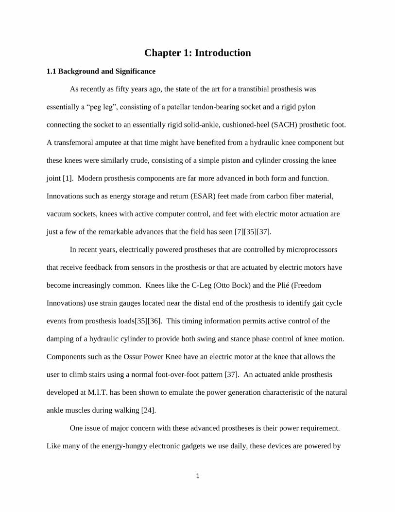
Chapter 1: Introduction
1.1 Background and Significance
As recently as fifty years ago, the state of the art for a transtibial prosthesis was
essentially a “peg leg”, consisting of a patellar tendon-bearing socket and a rigid pylon
connecting the socket to an essentially rigid solid-ankle, cushioned-heel (SACH) prosthetic foot.
A transfemoral amputee at that time might have benefited from a hydraulic knee component but
these knees were similarly crude, consisting of a simple piston and cylinder crossing the knee
joint [1]. Modern prosthesis components are far more advanced in both form and function.
Innovations such as energy storage and return (ESAR) feet made from carbon fiber material,
vacuum sockets, knees with active computer control, and feet with electric motor actuation are
just a few of the remarkable advances that the field has seen [7][35][37].
In recent years, electrically powered prostheses that are controlled by microprocessors
that receive feedback from sensors in the prosthesis or that are actuated by electric motors have
become increasingly common. Knees like the C-Leg (Otto Bock) and the Plié (Freedom
Innovations) use strain gauges located near the distal end of the prosthesis to identify gait cycle
events from prosthesis loads[35][36]. This timing information permits active control of the
damping of a hydraulic cylinder to provide both swing and stance phase control of knee motion.
Components such as the Ossur Power Knee have an electric motor at the knee that allows the
user to climb stairs using a normal foot-over-foot pattern [37]. An actuated ankle prosthesis
developed at M.I.T. has been shown to emulate the power generation characteristic of the natural
ankle muscles during walking [24].
One issue of major concern with these advanced prostheses is their power requirement.
Like many of the energy-hungry electronic gadgets we use daily, these devices are powered by
2
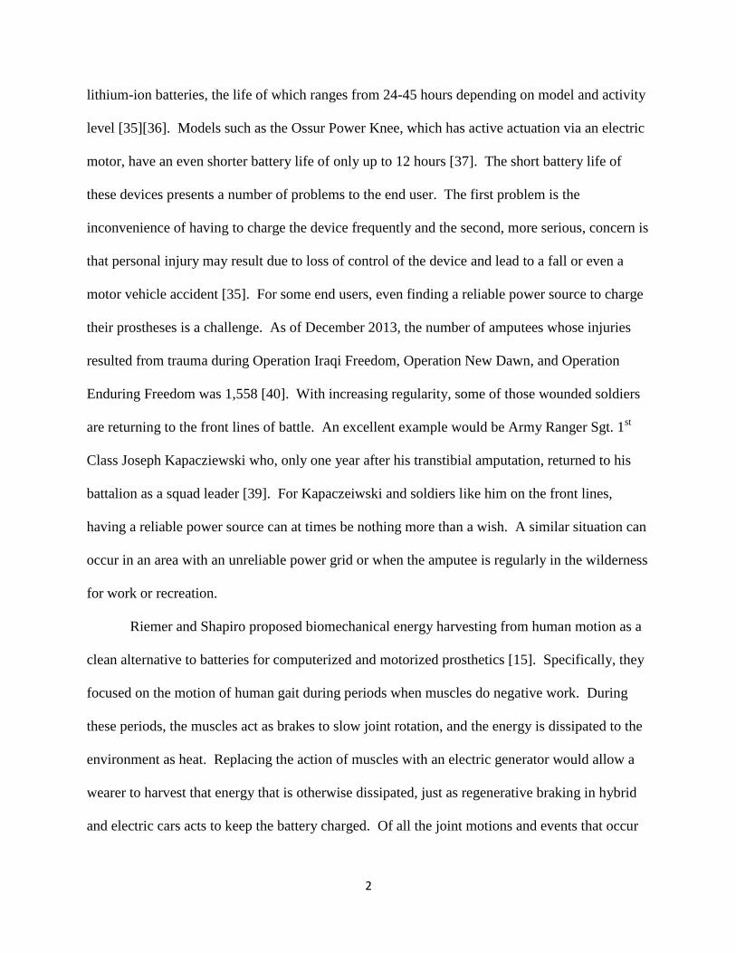
lithium-ion batteries, the life of which ranges from 24-45 hours depending on model and activity
level [35][36]. Models such as the Ossur Power Knee, which has active actuation via an electric
motor, have an even shorter battery life of only up to 12 hours [37]. The short battery life of
these devices presents a number of problems to the end user. The first problem is the
inconvenience of having to charge the device frequently and the second, more serious, concern is
that personal injury may result due to loss of control of the device and lead to a fall or even a
motor vehicle accident [35]. For some end users, even finding a reliable power source to charge
their prostheses is a challenge. As of December 2013, the number of amputees whose injuries
resulted from trauma during Operation Iraqi Freedom, Operation New Dawn, and Operation
Enduring Freedom was 1,558 [40]. With increasing regularity, some of those wounded soldiers
are returning to the front lines of battle. An excellent example would be Army Ranger Sgt. 1st
Class Joseph Kapacziewski who, only one year after his transtibial amputation, returned to his
battalion as a squad leader [39]. For Kapaczeiwski and soldiers like him on the front lines,
having a reliable power source can at times be nothing more than a wish. A similar situation can
occur in an area with an unreliable power grid or when the amputee is regularly in the wilderness
for work or recreation.
Riemer and Shapiro proposed biomechanical energy harvesting from human motion as a
clean alternative to batteries for computerized and motorized prosthetics [15]. Specifically, they
focused on the motion of human gait during periods when muscles do negative work. During
these periods, the muscles act as brakes to slow joint rotation, and the energy is dissipated to the
environment as heat. Replacing the action of muscles with an electric generator would allow a
wearer to harvest that energy that is otherwise dissipated, just as regenerative braking in hybrid
and electric cars acts to keep the battery charged. Of all the joint motions and events that occur
3
over one stride of human gait, Riemer and Shapiro select heel strike compression, knee rotation,
and ankle rotation as good candidates for energy harvesting, as much of the energy associated
with these motions is recoverable negative work. Furthermore, these motions are approximated
well by a single degree of freedom, simplifying the design of an energy harvesting device, as the
motion occurs about or along only a single axis [15].
The goal of this thesis is to investigate the effects of introducing a biomechanical energy
harvester on amputee gait. Specifically, we will consider a harvester that is incorporated into a
lower limb prosthesis by replacing the pylon component that connects the socket to the foot
prosthesis. Through motion analysis of amputee subjects and forward dynamic computer
simulations, we will attempt to determine how gait is affected when such an energy harvester
removes energy with every step and whether those changes have the potential to negatively
affect gait mechanics. We will also explore the properties of the energy harvester to determine
how the stiffness and damping characteristics affect gait mechanics.
1.2 Overview of Previous Work
Attempts to harvest energy from human gait have taken several forms in recent years.
One method incorporated into several devices has been to use the energy-absorbing negative
work usually performed by muscles to back-drive small electric motors as generators to produce
electricity. Donelan et al. (2008) developed a knee-mounted energy harvester that generates
electricity using a DC brushless motor as a generator with minimal additional user effort. The
device selectively engages the generator at the end of swing phase, assisting the knee flexors in
slowing knee extension. The device produced approximately 5 W of power without a significant
increase in metabolic cost [13]. Starner and Paradiso (2001) constructed a similar shoe-mounted
4
device that absorbed energy at heel strike. This device was able to produce 250 mW of power,
which is enough to power small electronics [17].
Other researchers have used piezo-electric materials to produce electricity from gait.
Most of these energy harvesters take advantage of the energy dissipated at heel strike to deform
the piezo-electric material. Starner and Paradiso (2001) were able to produce a considerable
peak power of 60 mW, from his device, which incorporated a piezo-electric material on a spring
steel backing. The average power produced by this device was only 1.8 mW, however, because
heel strike lasts only a short amount of time [17]. Shenck and Paradiso (2001) improved on this
design, configuring two of these devices back-to-back in a “clamshell” configuration that was
able to produce energy over more of the gait cycle, producing 8.4 mW of average power. They
also devised a flexible device to harvest energy from the sole of the shoe bending under the ball
of the foot that produced 1.3 mW [14]. Clearly these piezo-electric devices, while small and
easily incorporated into footwear, have not to date matched the power production of methods
that use rotary generators.
Other researchers have devised prosthetics that capture energy from motion, but instead
of storing it as electricity, they return the energy at a point in the gait cycle where amputees are
usually unable to provide positive work. Collins and Kuo (2010) developed a prosthetic foot
with separate rearfoot and forefoot sections that stores energy captured at heel strike and returns
it in a controlled manner at push off as positive ankle work where the lack of musculature
crossing the ankle in amputees robs them of the ability to produce such work[12]. The device
works by compressing a spring at heel strike. The spring is then released when sufficient force is
detected on the forefoot portion of the prosthetic foot, providing push off assistance. In a similar
fashion, Farber and Jacobson (1995) devised a prosthetic knee for transfemoral amputees that
5
also provides energy recovery for an improved knee extension moment during stance. They
reported energy cost to amputee subjects decreasing by an average of 35% when using the
energy-recovering knee[18].
1.3 Specific Aims
This thesis addressed the following specific aims:
1. Experimentally identify changes in amputee gait due to the effects of varied energy
harvesting properties using an adjustable energy harvesting pylon (EHP) analog created
from a bicycle shock absorber. Using video-based motion analysis and force platforms,
amputee gait was recorded under different EHP stiffness and damping settings.
Following computation of joint kinematics and kinetics, the changes in these variables
that occur as properties of the EHP are varied were examined.
2. Use a computer simulation of unilateral transtibial amputee gait to characterize changes
in gait due to different EPH settings and compare to our experimental results. Creating
forward dynamic simulations of an amputee walking with an EHP allowed us to explore a
much wider array of EHP parameter combinations that are possible with live amputee
subjects. We ran simulations over 5 levels of spring stiffness and 6 levels of damping for
a total of 30 parameter combinations.
We hypothesized the following:
1. When the real EHP analog and amputee model EHP damping is increased and spring
stiffness is increased, causing more energy to be dissipated at heel strike and less
energy to be returned at push-off, torque and power generated at push-off by the
plantarflexor muscles crossing the trailing intact-side ankle will increase.
Rationale: During normal walking, a substantial amount of energy is generated by
6
the trailing leg plantarflexor muscles during push-off to keep the body moving
forward. Forward energy is lost during the leading leg heel strike collision and
previous findings indicate that a compliant prosthesis will store and return more
energy than a stiff one. If we increase this heel strike energy loss and decrease
energy return, the plantarflexors will generate more energy to compensate.
2. When the real EHP analog and amputee model EHP damping is increased and spring
stiffness is increased, causing more energy to be removed at heel strike and less
energy to be returned at push-off, torque and power generated by the intact-side hip
flexors will increase at push-off.
Rationale: Studies of geriatric gait have found that elderly subjects appear to
compensate for weakened plantar flexors by generate more power with the hip flexors
in order to maintain gait velocity.
3. In the proposed simulations of amputee gait described above, when damping is
increased and spring stiffness is increased in the amputee model EHP causing more
energy to be dissipated at heel strike and less energy to be returned at push off, center
of mass (COM) acceleration in the vertical direction will also increase.
Rationale: The trailing leg plantarflexors are also a major energy source that
accelerates the COM over the stance leg to keep the body moving forward during
gait. If energy is removed from the gait cycle at heel strike, the plantar flexors must
compensate with greater forces to accelerate the COM over the stance leg.
4. In the proposed simulations of amputee gait described above, when damping is
increased and spring stiffness is increased in the amputee model EHP causing more
energy to be dissipated at heel strike and less energy to be returned at push off, some
7
combination of stiffness and damping within a range of likely values will disrupt the
gait, perhaps by preventing a successful optimization or by requiring inordinately
large joint moments or powers.
Rationale: It is well known that amputees must generate higher joint moments and
powers to compensate for muscle forces they no longer have, which leads to fatigue
and the possibility of falls. With additional energy being taken from their gait, even
higher joint moments and powers are required to compensate for the lost energy.
8
Chapter 2: Review of the Literature
2.1 Biomechanical energy harvesting
Biomechanical energy harvesting, also known as energy scavenging, has been an active
area of research in recent years. The fundamental idea is to collect energy from motion that
would otherwise be dissipated to the environment, and return or store it in some useful way.
Where this energy comes from and how it is collected varies greatly throughout the research
community. Starner and Paradiso (2004) as well as Riemer and Shapiro (2011) identify several
sources of recoverable energy as potential sources for energy harvesters: Thermal radiation,
collision energy at heel strike, and negative work done by muscles during eccentric
contraction[17][14]. Thermal radiation is generally of little interest, as it would require a special
garment to be worn over most of the body to capture thermal radiation form the skin. The other
two sources are widely targeted by researchers, as they should be easier to capture with small
wearable devices.
The knee is commonly targeted as a source of recoverable negative work. Farber and
Jacobson (1995) harvested the work performed at the knee in early stance during weight
acceptance with a prosthetic knee component that incorporated a shock absorber [18]. Donelan
et al. (2008) developed a knee mounted energy harvester that selectively engages the harvesting
mechanism during late swing, when the hamstrings do negative work to slow knee extension.
Instead of this work being done on the muscles it was absorbed by the energy harvester[13].
Most researchers that harvest energy from foot contact with the ground take advantage of
heel strike. Collins and Kuo (2010) captured the energy dissipated at heel strike with a
prosthetic foot that incorporates a mechanism similar to that developed by Farber and Jacobson
(1995) [12]. Shenck and Paradiso (2001) and Kymissis et al. (1998) devised several wearable
9
shoe-mounted devices that were designed to harvest collision energy at heel strike, and their
designs were improvements the device presented in Starner and Paradiso (2001) Some of these
designs also harvested energy dissipated to the ground during push off [14][27][17].
Most researchers who have developed such energy harvesters hope to store this energy so
that it might be used for powering electronic devices, but a few, such as Collins and Kuo (2010)
and Farber and Jacobson (1995), have attempted to return it to the body at a specific time to
increase the energetic efficiency of walking. Collins and Kuo’s device harvests and stores the
energy dissipated at heel strike in a spring and returns it at toe off to increase push off power to a
degree that is twice as great as what is possible with a conventional prosthesis. Farber and
Jacobson’s device harvested the work performed by the knee muscles at weight acceptance and
returned it at push off, resulting in a 35% decrease in energy costs to amputee subjects wearing
the device [12][18].
Several methods for capturing energy have been implemented in these energy harvesting
devices. The amount of energy captured and additional energetic cost to the user differs between
the specific devices used. For the devices described above that return the energy later in the gait
cycle, the energy is merely stored in a compressed spring and returned later. For amputees
wearing these devices, there may be a reduction in metabolic cost, as the energy returned does
not have to be derived from metabolic sources. Farber and Jacobson reduced the energetic cost
of locomotion by 35%, while Collins and Kuo’s device reduced this cost by 14% [18][12].
Two other mechanisms commonly used for capturing energy and converting it to
electricity are rotary electric motors used as generators and piezo-electric materials. Piezo-
electric materials are used most often in heel strike devices and flexible shoe-mounted devices
like those devised by Shenck and Paradiso (2001) and Kymissis et al. (1998) [14][27]. Piezo-
10
electric materials offer certain advantages, such as being lightweight and low additional energy
cost, as it takes little effort to deform them. However, their power output is limited to the 100
mW scale. Rotary generators, on the other hand, like those used by Donelan et al (2008), have a
much higher power output, but come with some additional energy cost. In generative breaking
mode, Donelan’s device was able to produce 4.8 ± 0.8 W with an increased metabolic power of 5
± 21 W, which was found to be an insignificant metabolic increase over the control condition
where the subject wore the device, but the energy harvesting component was disconnected [13].
2.2 Studies of amputee gait with varying prosthesis characteristics
Many researchers have used video-based gait analysis and force plates to study the gait of
amputees, as this approach is the gold standard method for evaluating the kinematics and kinetics
of human gait. Specifically, many researchers have used gait analysis to investigate the
differences that arise from variation in properties of different prosthesis components in order to
minimize metabolic cost to the user. It is well known in the biomechanics community that
amputees as a population vary greatly in their gait. The metrics used by researchers to evaluate
the effects of different prosthesis parameters are just as varied across studies.
In a study similar to the present thesis, Gard and Konz (2003) studied the effect of a
shock absorbing pylon on the gait of unilateral transtibial amputees. They looked for differences
in walking speed, step length symmetry, pelvic obliquity, and vertical and anterior-posterior
ground reaction force with three different spring stiffnesses of 73, 108, and 137 kN/m. They
found no significant differences in gait parameters due to pylon stiffness with the exception of a
significant decrease in the force transient of prosthetic side weight acceptance at the fastest
walking speeds with decreasing spring stiffness [30]. In a similar fashion, Zelik et.al. (2011)
tested three different spring stiffnesses in the energy recycling foot of Collins and Kuo described
11
above looking for differences in work performed on the COM, oxygen consumption, and ankle,
knee, and hip power. They found greater energy storage in the spring translated to more ankle
work being performed at the subsequent push off, and energy storage in the foot increased with
decreasing stiffness. Prosthetic-side work on the COM during push off also followed this trend.
The intact side work on the COM did not show any significant trend with spring stiffness, nor
did prosthetic or intact side knee and hip power. Metabolic rate was also affected by spring
stiffness, but the medium stiffness spring actually produced the lowest measure opposed to the
stiff or compliant springs [31]. Fey, Klute, and Neptune (2011) found similar results studying
the effect of prosthetic keel foot stiffness on transtibial amputees. They also found energy
returned by the prosthesis increased with decreasing stiffness. They examined many gait
parameters including ground reaction forces, joint kinetics, and EMG signals and found varying
significant trends with foot stiffness. However, they were able to identify a trade-off that occurs
with varying stiffness where gait parameters that contribute to body support during stance
increase with increasing stiffness and parameters that contribute for forward propulsion increase
with decreasing stiffness [33]. Ventura, Klute, and Neptune (2011) found the same trade-off in
transtibial amputee gait with prosthetic ankle components of varying stiffness attached to the
same prosthetic foot [32]. Segal et al (2012) did another study examining the effect of the
controlled energy storage and return (CESR) foot (the more compliant condition) on transtibial
amputee ambulation in comparison to a conventional prosthetic foot. What made this study
unique is that they paid particular attention to the intact-side joint kinetics as well as the
prosthetic side. They found similar results on the prosthetic side as the latter three studies, but
they also found significantly lower intact side ankle power and COM work and significantly
lower intact-side knee power bursts while using the CESR foot, where the other studies did not
12
[34]. While the differences found by each author vary from study to study, as does whether
those differences are significant, the finding common to these studies seems to be that energy
stored and returned in the prosthesis increases with prosthesis compliance. This translates into
increased energy return from the prosthesis leading to reduced joint moments and powers.
2.3 Computer simulation of amputee gait and prosthesis properties
Computer simulations of human gait are widely used to investigate a multitude of
questions concerning normal human gait. Many researchers interested in amputees also use
computer simulations to model amputee gait as a means to study both differences between
amputee and normal gait and optimize prosthesis properties. Piazza (2006) reviewed the
application of these types of computer simulations, called forward dynamic musculoskeletal
simulations, to the study of pathological gait, including amputee gait. Some of the main
advantages of these types of simulations are that they permit monitoring of every conceivable
physical variable [22]. This allows the researcher to examine characteristics of gait, such as
individual muscle contributions, that would be impossible to examine in experiments on human
subjects without highly invasive techniques. Simulation also allows us to run potentially
dangerous experiments in which, for example, the subject (model) runs a large risk of falling
down. With regard to pathological gait, simulation can be used to determine causes of and
compensatory mechanisms in different gait pathologies.
One critical choice that determines simulation output is the objective function - the value
minimized to determine the controls that produce the motions of walking. Some investigators
have minimized differences between simulated and experimentally measured gait, but as Brugger
and Schmiedmayer (2003) have pointed out, tracking the movement of a real human with a
vastly simplified model can produce unrealistic joint forces and moments, and it is often better to

13
optimize other parameters [29][5]. Silverman and Neptune (2012) use a forward dynamic
simulation to explore muscle and prosthesis contributions to amputee gait. They use a muscle
driven model that uses muscle excitations as controls and a simulated annealing algorithms to
minimize a cost function comparing simulated and experimental ground reaction forces (GRFs)
and joint kinematics. They were able to reproduce experimental walking data, but they could also
probe the individual muscles and quantified differences in muscle kinetics relating to body
support and propulsion during stance between amputees and non-amputees [19]. Fey, Klute, and
Neptune (2012) use a similar muscle driven model in a simulation to optimize the stiffness of a
prosthetic energy storage and return foot. Their cost function minimized muscle energy
consumption and intact side knee loading and was also optimized using a simulated annealing
optimization algorithm. Their model included a detailed model of the prosthetic foot which
consisted of 22 rigid segments connected by revolute joints whose stiffness and damping could
be varied to achieve different overall foot stiffnesses. They found that all simulations decreased
heel stiffness and increased midfoot stiffness. However, optimizing for either metabolic cost or
knee loading decreased and increased toe stiffness, respectively [20][21]. Bregman et. al. (2011)
found similar results while studying simulations of ankle foot orthosis stiffness on energy cost of
walking. While orthoses and prostheses are different classes of devices, the model of the AFO
side used in this study was essentially the same as the prosthesis models used in amputee studies.
They found an optimal stiffness that maximized energy return at the right moment in the gait
cycle which minimized energy cost. Energy return increased with decreasing stiffness (in a
manner similar to that found in experimental studies) but the stiffness that minimized energy cost
was not the lowest stiffness. At the lowest stiffness, push off occurred to late in the gait cycle
and led to a suboptimal energy cost [28].

14
One thing common to all the simulation and amputee studies presented in this review is
that increased prosthesis compliance seems to allow more energy to be stored and returned by
the prosthesis. This finding raises the possibility that the energy stored by a compliant spring
can be harvested rather than returned from a spring.
15
Chapter 3: Methods
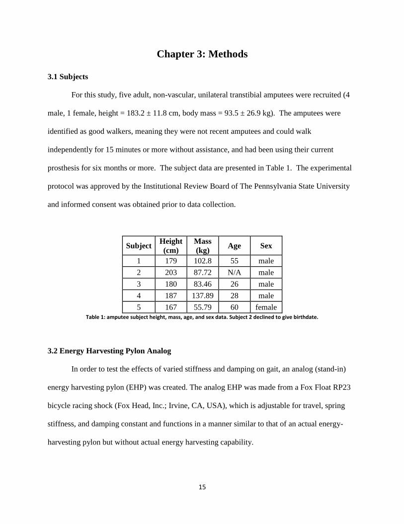
3.1 Subjects
For this study, five adult, non-vascular, unilateral transtibial amputees were recruited (4
male, 1 female, height = 183.2 ± 11.8 cm, body mass = 93.5 ± 26.9 kg). The amputees were
identified as good walkers, meaning they were not recent amputees and could walk
independently for 15 minutes or more without assistance, and had been using their current
prosthesis for six months or more. The subject data are presented in Table 1. The experimental
protocol was approved by the Institutional Review Board of The Pennsylvania State University
and informed consent was obtained prior to data collection.
Subject Height
(cm)
Mass
(kg) Age Sex
1 179 102.8 55 male
2 203 87.72 N/A male
3 180 83.46 26 male
4 187 137.89 28 male
5 167 55.79 60 female
Table 1: amputee subject height, mass, age, and sex data. Subject 2 declined to give birthdate.
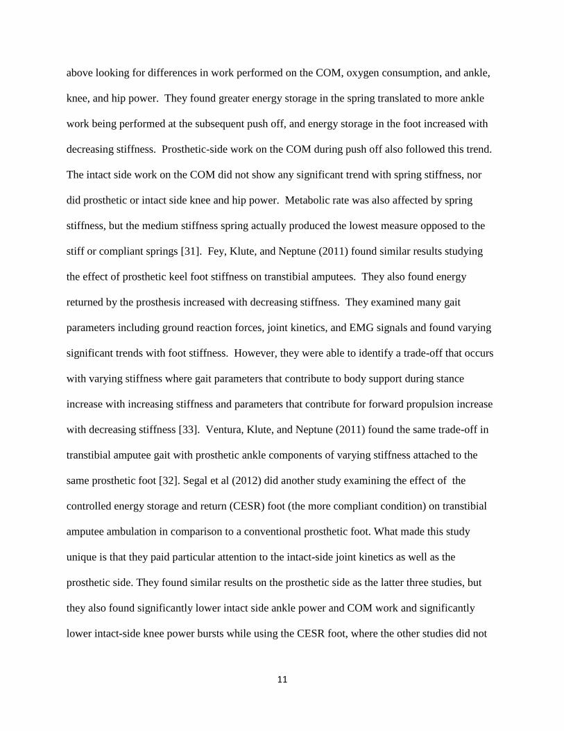
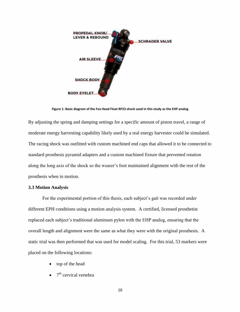
3.2 Energy Harvesting Pylon Analog
In order to test the effects of varied stiffness and damping on gait, an analog (stand-in)
energy harvesting pylon (EHP) was created. The analog EHP was made from a Fox Float RP23
bicycle racing shock (Fox Head, Inc.; Irvine, CA, USA), which is adjustable for travel, spring
stiffness, and damping constant and functions in a manner similar to that of an actual energy-
harvesting pylon but without actual energy harvesting capability.
16
Figure 1: Basic diagram of the Fox Head Float RP23 shock used in this study as the EHP analog
By adjusting the spring and damping settings for a specific amount of piston travel, a range of
moderate energy harvesting capability likely used by a real energy harvester could be simulated.
The racing shock was outfitted with custom machined end caps that allowed it to be connected to
standard prosthesis pyramid adapters and a custom machined fixture that prevented rotation
along the long axis of the shock so the wearer’s foot maintained alignment with the rest of the
prosthesis when in motion.
3.3 Motion Analysis
For the experimental portion of this thesis, each subject’s gait was recorded under
different EPH conditions using a motion analysis system. A certified, licensed prosthetist
replaced each subject’s traditional aluminum pylon with the EHP analog, ensuring that the
overall length and alignment were the same as what they were with the original prosthesis. A
static trial was then performed that was used for model scaling. For this trial, 53 markers were
placed on the following locations:
top of the head
7th
cervical vertebra

17
manubrium
xiphiod process
top and bottom of the pylon piston
acromion (R and L)
anterior superior iliac spine (R and L)
greater trochanter (R and L)
lateral femoral epicondyles (R and L)
lateral malleoli (R and L)
distal tip of the 2nd
ray of the foot (R and L)
back of the heel (R and L)
Marker clusters (four markers fixed to a piece of form-fitting, rigid plastic) were also
placed on the anterolateral aspect of the thighs and shanks, on the superior surface of the feet,
and over the sacrum (to track the pelvis). Pressure in the air spring was then set to a pressure of
160 lb in-2
, the maximum pressure recommended by the manufacturer, using a bicycle pump
with attached pressure gauge. The damping was set to the “pro-pedal” setting, making the pylon
essentially rigid under loads experienced during standing or walking. The subject then
performed a static trial by standing still on each force plate with knees locked and elbows bent at
90° for 3.0 s.
18
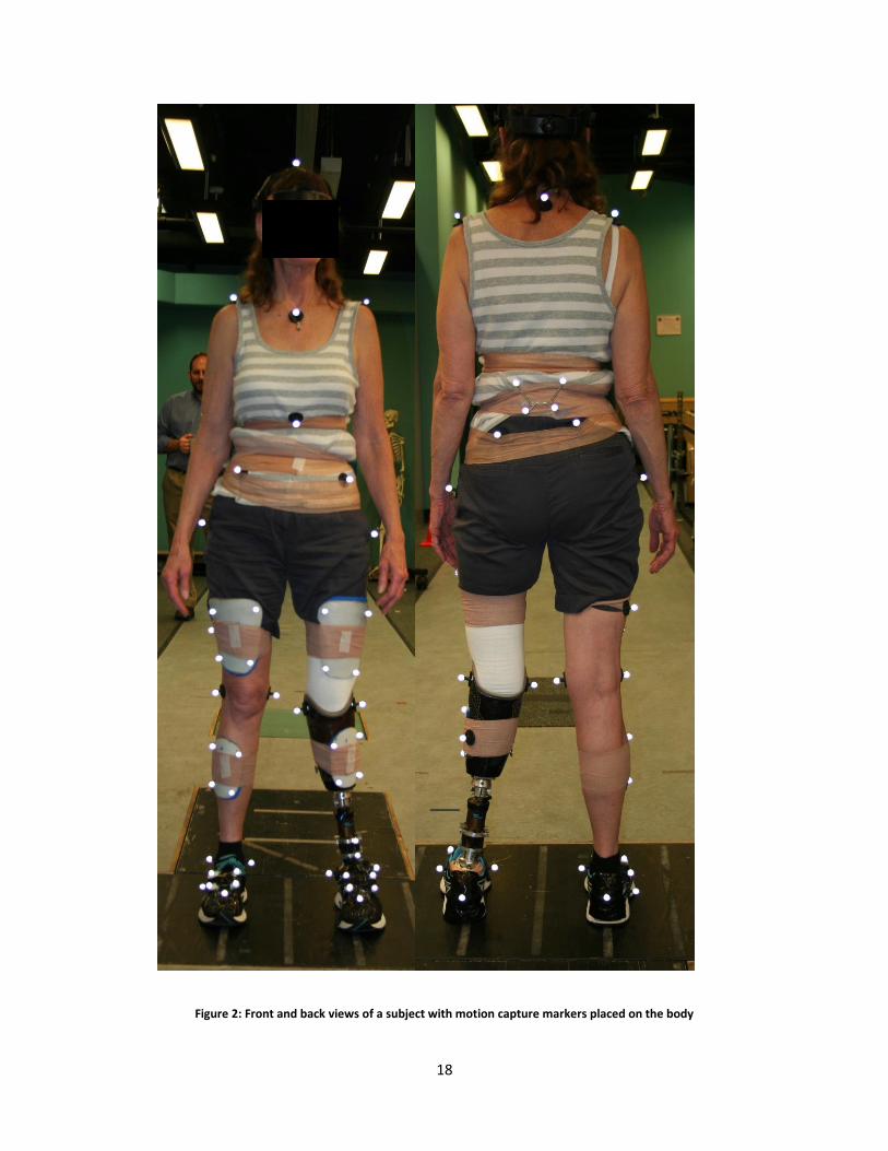
Figure 2: Front and back views of a subject with motion capture markers placed on the body
19
For the dynamic walking trials the same marker set was used but with the lower
extremity anatomical landmark markers (ASIS, greater trochanter, lateral femoral epicondyles,
and lateral malleoli) removed, leaving only the clusters, upper body, heel, and toe markers.
Walking trials were then collected for five different EHP settings:
rigid
stiff spring/high damping
stiff spring/low damping
compliant spring/high damping
compliant spring/low damping
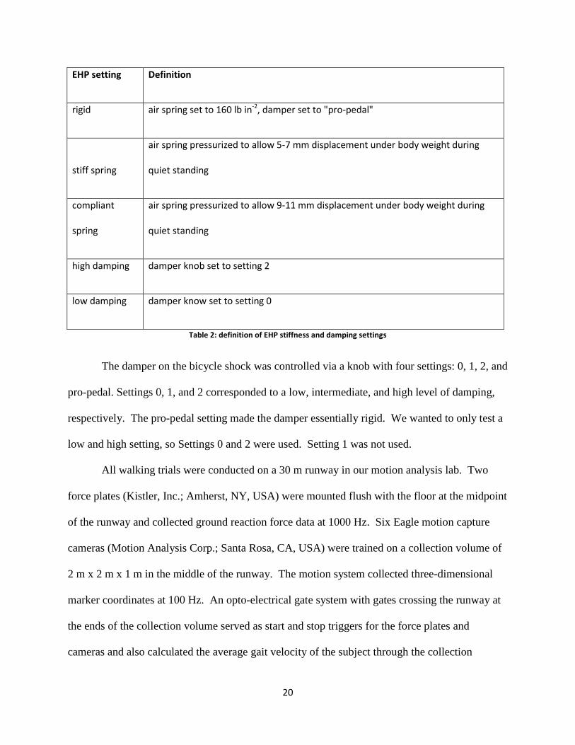
Table 2 defines each EHP spring and damper setting listed above.
20
EHP setting Definition
rigid air spring set to 160 lb in-2, damper set to "pro-pedal"
stiff spring
air spring pressurized to allow 5-7 mm displacement under body weight during
quiet standing
compliant
spring
air spring pressurized to allow 9-11 mm displacement under body weight during
quiet standing
high damping damper knob set to setting 2
low damping damper know set to setting 0
Table 2: definition of EHP stiffness and damping settings
The damper on the bicycle shock was controlled via a knob with four settings: 0, 1, 2, and
pro-pedal. Settings 0, 1, and 2 corresponded to a low, intermediate, and high level of damping,
respectively. The pro-pedal setting made the damper essentially rigid. We wanted to only test a
low and high setting, so Settings 0 and 2 were used. Setting 1 was not used.
All walking trials were conducted on a 30 m runway in our motion analysis lab. Two
force plates (Kistler, Inc.; Amherst, NY, USA) were mounted flush with the floor at the midpoint
of the runway and collected ground reaction force data at 1000 Hz. Six Eagle motion capture
cameras (Motion Analysis Corp.; Santa Rosa, CA, USA) were trained on a collection volume of
2 m x 2 m x 1 m in the middle of the runway. The motion system collected three-dimensional
marker coordinates at 100 Hz. An opto-electrical gate system with gates crossing the runway at
the ends of the collection volume served as start and stop triggers for the force plates and
cameras and also calculated the average gait velocity of the subject through the collection
21
volume. Before collection of data, subjects performed five practice walking trials across the
runway at a self-selected speed to establish their average gait velocity and to identify a starting
point that would allow them to hit the force plates correctly; i.e., having a single foot fall on each
force plate with no overlap of the foot onto the other force plate or the runway, preferably
without targeting the force plates. The five practice trials were made with the subject’s regular
prosthesis pylon, and the over-ground walking speeds were averaged to calculate an average gait
velocity for each subject. Subjects were asked to repeat their average gait velocity for each
subsequent trial as closely as possible. The prosthetist then fit the subject with the EHP,
ensuring that their prosthesis length and alignment were the same as with their original
prosthesis. Subjects walked a number of trials for each combination of spring and damping
constants until three to four successful trials for each condition were collected. We attempted to
collect as many as five successful trials, but no subject was able to achieve this; we limited each
subject to 3-4 trials in order to minimize fatigue. A successful trial consisted of a clean footfall
on each force plate with consecutive steps while staying within 10% of their target speed. Each
subject started with the rigid condition, but the other four conditions were attempted in random
order. Subjects were allowed to make a self-selected number of practice trials (generally two or
three) with each EHP condition to allow them to become familiar with the new feel of their
prosthesis before data were collected. Subjects were also allowed to rest as needed between
trials, as they typically conducted about 10 trials per condition (practice and failures included),
which was a tiring amount of walking for some subjects.
3.4 Data Processing
All motion capture data were analyzed in OpenSim, an open-source, physics-based
musculoskeletal modeling software that can calculate gait kinematics and kinetics based on
22
motion capture data [3]. OpenSim is maintained by the Simbios NIH Center for Biomedical
Computation at Stanford University. A generic musculoskeletal model was scaled in OpenSim
to the dimensions of each subject using an iterative technique based on the best practices
recommendations for maximum tolerable marker error outlined in the OpenSim user manual.
This technique is explained as follows. To create a scaled model of the subject, we used the
"Gait 2354" example model provided in OpenSim as the generic model. This model is a 23
degree of freedom (DoF) head-arms-trunk (HAT) model where the head, arms, and trunk are
lumped together as one segment and the pelvis and lower limbs are fully represented. Next,
virtual markers (computer representations of the markers placed on the subject) were placed on
the model only at the anatomical bony land marks. The Scale Tool is an algorithm in OpenSim
that is used to properly scale the dimensions of the body segments of the generic model to those
of the subject and to adjust the joint angles of the model to match the position of the subject in
the static pose. Good scaling is highly dependent on accurate placement of the virtual markers
on the model so that they match the locations of the real markers on the subject. We used only
the anatomical landmark markers for scaling because we can more accurately locate the same
points on the model skeleton relative to the real anatomical bony landmark markers on the
subject skeleton. The clusters of markers, on the other hand, are generally placed over areas of
the body where large amounts of soft body tissue make it difficult to place the virtual markers
accurately on the generic model. Inputs to the scale tool are the generic model with virtual
markers, a file containing the time history of the global position of each markers on the subject
during the static pose, and a settings file containing a scaling weight for each virtual marker that
dictates how well it should be matched to the corresponding subject marker and a list of which
markers to include in scaling. Each virtual marker was given the same weight of 1.0. The Scale
23
Tool scales each body segment of the model based on measurements made between
corresponding pairs of markers on the model and on the subject. It then performs a least squares
optimization to position the model such that all the virtual markers match the global position of
the subject markers as closely as possible. The scale tool also reports the RMS and maximum
error between the virtual and subject markers. Best practices guidelines from the developers of
OpenSim dictate that maximum errors on bony landmark markers should be less than 2 cm and
the RMS error should be less than 1 cm. Our scaling process allowed us to meet those
tolerances. To achieve this, once the RMS and maximum errors were noted, we looked at each
virtual marker and noted approximately how far and in what direction it should be moved to
match up directly with the experimental marker. The scaled model was then deleted, and the
marker adjustments taken from the scaled model were made on the generic model, and the scale
tool was run again. This process of noting the error and marker adjustments, making those
adjustments to the generic model, and scaling again, was repeated until the RMS and maximum
errors were at or below the best practice standards. It should also be noted here that photos of
the subject in the static pose were used while adjusting the markers to make sure the virtual
marker position did not become unrealistic and to estimate the joint angles of the subject in the
static pose as an accuracy validation of the model's static pose. Once a model is created with
acceptable marker error and an accurate static pose, the cluster markers could then be added to
the generic model and the scale tool run one last time. This time however, the scale tool will
properly scale the body segments, put the model in the same static position as the subject (using
only the bony landmark markers), and then map all the virtual cluster markers to the exact
position of the corresponding subject markers.
24
Inverse kinematics (IK) were then calculated in OpenSim for each trial. The inverse
kinematics tool in OpenSim allows us to back-calculate the joint angles of the subject from the
recorded marker positions during gait. Inputs to the IK tool are similar to the scaling tool and
include a scaled model with virtual markers, a file containing the time history of all the subject
marker global positions, and a setup file containing marker optimization weights and a task file
dictating which markers are used in the optimization at each time step. We used the IK tool with
all the markers having equal weight of 1.0 and the markers used are now only the cluster
markers, ASIS markers, and upper body markers. We do not use the anatomical landmark
markers at the joints because soft tissue deformation around the joints is much more significant
than the middle of body segments when the joints flex. This introduces error to the anatomical
landmark markers with respect to their relative position to the skeleton. The IK tool works in a
similar fashion to the scale tool in that it uses a least squares optimization to adjust the joint
angles such that the virtual markers on the model match the position of the subject markers for
each frame in the trial. The tool reports RMS and maximum marker errors for each frame and
marker errors for all frames were within the best practices standards (2 cm and 4 cm,
respectively, for IK errors) and served as a validation of sorts that our scaling process worked
correctly. In the end, IK allows us to have the joint angle trajectories for each joint in the model
over the course of the trial.
Inverse dynamics were also calculated in OpenSim for each trial. Inverse dynamics (ID)
allow us to calculate the joint torques based on the joint motions solved for by the IK tool,
external forces recorded by the force plates, and inertial properties of the body segments of the
model. For this study, the inertial parameters of each segment were simply the inertial
parameters of the generic model scaled to that of the subject. Inputs to the ID tool include the
25
scaled model, the motion file containing the IK tool output and an external forces file containing
the time history of any external forces on the model (in this case, these are ground reaction
forces). Output of the ID tool is a time history of joint torques that produce the observed motion.
Custom MATLAB code incorporating the Biomechanical ToolKit (BTK) tool box was used to
convert the analog reading from the force plates in .c3d files to the necessary .mot files needed to
apply external forces in the ID calculation. Because only two force plates were available, we
were not able to capture motion data and complete force plate data for a full gait cycle. Force
plate data was collected from the initial heel strike on Force Plate 1, to contralateral toe off on
Force Plate 2. The trailing leg during double support at heel strike on Force Plate 1 does not
have ground reaction force data, nor does the leading leg during double support at contralateral
toe off on Force Plate 2. Therefore, while inverse kinematics and dynamics were calculated for
a full gait cycle, inverse dynamics were only truly valid from trailing leg toe off (when the
leading foot was on Force Plate 1) to the subsequent contralateral heel strike beyond Force Plate
2, or about 88% of a gait cycle. The fact that we were not able to capture complete data for a full
gait cycle did not impact our results, because the gait events we wished to analyze occurred
during double support when both feet were on the force plates and the subsequent early swing
stage of the trailing intact leg.
3.5 Data Analysis
Custom MATLAB code was used to calculate and plot intact-leg plantarflexor and hip
flexor moments and powers. All trials for each subject were plotted against percent gait cycle to
visualize any obvious trends. Values for the peak plantar flexor and hip flexor moment and
power corresponding to the gait event of interest (intact side toe off and early swing) were
manually extracted from the plots and tabulated. In extracting these peak moment and power
26
values, rarely did they occur at the same instant as toe off. Furthermore, peaks occurring around
the gait event of interest were not always the highest peak on the plot. Therefore, as a
precautionary measure, gait percentage of the peak moment and power values were cross
checked with kinetic and kinematic indicators of gait events to ensure the extracted value
corresponded to the correct gait event. Most of the gait events were determined by appearance
or disappearance of a ground reaction force, where a heel strike was defined as the first frame
where a ground reaction force rises above a 3 N threshold, and toe off was defined as the first
frame when the ground reaction force falls below a 3 N threshold. Gait events that could not be
determined from force plate data because they happened off the force plates were determined by
applying the principles of the algorithm developed by Hreljac and Marshall (2000) for
determining gait events using kinematic marker data [23]. A Savitsky-Golay 7-point cubic
interpolant algorithm was used in MATLAB to calculate the first, second, and third derivatives
of the position data for the heel and toe markers. Graphs of the acceleration and jerk for each
marker were then examined for acceleration peaks and jerk zero-crossings that correspond to
heel strike and toe off, as described by Hreljac and Marshall (2000). To verify that this method
of event detection was accurate, the frame numbers of the events detected by the force plates
were compared to the same events predicted by the Hreljac and Marshall (2000) method.
Prediction of heel strike was within 0-2 frames of the event detected by the force plate, and toe
off was within 0-3 frames. With all the gait events in each trail identified, we could be certain
that the extracted data points corresponded to the correct gait event of interest.
To determine peak intact-side plantarflexor and hip flexor moments, plots of the
respective joint moments were created in MATLAB and manually examined to determine when
peak moment occurred corresponding to toe off/early swing. The values of those peaks were
27
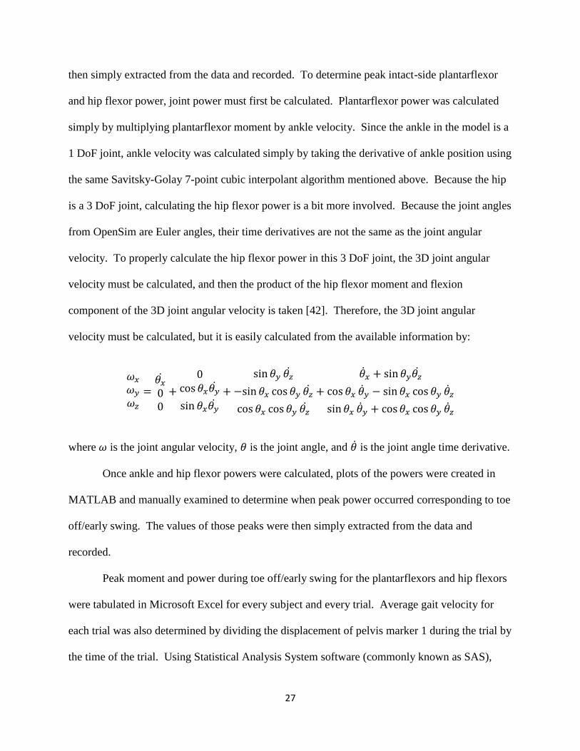
then simply extracted from the data and recorded. To determine peak intact-side plantarflexor
and hip flexor power, joint power must first be calculated. Plantarflexor power was calculated
simply by multiplying plantarflexor moment by ankle velocity. Since the ankle in the model is a
1 DoF joint, ankle velocity was calculated simply by taking the derivative of ankle position using
the same Savitsky-Golay 7-point cubic interpolant algorithm mentioned above. Because the hip
is a 3 DoF joint, calculating the hip flexor power is a bit more involved. Because the joint angles
from OpenSim are Euler angles, their time derivatives are not the same as the joint angular
velocity. To properly calculate the hip flexor power in this 3 DoF joint, the 3D joint angular
velocity must be calculated, and then the product of the hip flexor moment and flexion
component of the 3D joint angular velocity is taken [42]. Therefore, the 3D joint angular
velocity must be calculated, but it is easily calculated from the available information by:
𝜔𝑥
𝜔𝑦
𝜔𝑧
=𝜃�̇�
00
+
0cos 𝜃𝑥𝜃�̇�
sin 𝜃𝑥𝜃�̇�
+
sin 𝜃𝑦 𝜃�̇�
−sin 𝜃𝑥 cos 𝜃𝑦 𝜃�̇�
cos 𝜃𝑥 cos 𝜃𝑦 𝜃�̇�
+
�̇�𝑥 + sin 𝜃𝑦𝜃�̇�
cos 𝜃𝑥 �̇�𝑦 − sin 𝜃𝑥 cos 𝜃𝑦 �̇�𝑧
sin 𝜃𝑥 �̇�𝑦 + cos 𝜃𝑥 cos 𝜃𝑦 �̇�𝑧
where 𝜔 is the joint angular velocity, 𝜃 is the joint angle, and �̇� is the joint angle time derivative.
Once ankle and hip flexor powers were calculated, plots of the powers were created in
MATLAB and manually examined to determine when peak power occurred corresponding to toe
off/early swing. The values of those peaks were then simply extracted from the data and
recorded.
Peak moment and power during toe off/early swing for the plantarflexors and hip flexors
were tabulated in Microsoft Excel for every subject and every trial. Average gait velocity for
each trial was also determined by dividing the displacement of pelvis marker 1 during the trial by
the time of the trial. Using Statistical Analysis System software (commonly known as SAS),

28
each subject’s data was analyzed using repeated measures ANCOVA to look for significant
trends in joint kinetics in response to varying EHP properties. One factor at five levels
corresponding to the five EHP conditions described previously was used. A covariance to gait
velocity was used in the analysis to account for differences in kinetics due to gait velocity.
Significance was determined to be a test with a p-value of 0.05 or less. Each subject was treated
as its own case study, and difference that were consistent across all subjects were not sought, as
we did not expect each subject to react in the same way to the different conditions.
3.6 Computer Simulations
We also conducted a sensitivity study using a computer simulation of amputee gait to
investigate the effects of varying EHP properties on gait mechanics and discern if gait mechanics
were severely affected. Using SIMM/Dynamics Pipeline, we created a biomechanical model of
an amputee wearing a below knee prosthesis with an EHP. The original model and simulation
was developed by Huseyin Celik, PhD, as part of his doctoral dissertation at The Pennsylvania
State University [2]. The model is a planar model (joint motion only occurs in the sagittal plane)
consisting of a lumped head, arms, trunk and pelvis segment, and left and right thighs, shanks,
and feet. The model is driven by 16 Hill-type muscle actuators that take an excitation as their
controls and produce a force according to excitation and current fiber length. The objective
function for the model was to find a set of controls (muscle activations) that made the model
traverse a set distance while minimizing muscle forces, trunk lean, and GRF spikes subject to a
number of constraints. A solution was found by optimizing the objective function using a
multiple-shooting algorithm. For a detailed description of the model and problem formulation
used in the simulation, the reader is referred to [2]. For this study, the model was modified to
represent a transtibial amputee by removing all the muscles crossing the right ankle and
29
replacing them with a damped torsional spring at the ankle joint representing the compliance
found in an energy storage and return foot. The shank segment of the prosthetic side was
separated into proximal and distal sections with a slider joint between them to represent the
telescoping motion that occurs in the EHP. Since we were not trying to represent any one
amputee subject, but rather a “typical” amputee, we arbitrarily set the length of the proximal
shank, which represents the residual limb, socket, and upper portion of the EHP to be 75%of the
original segment length, and the distal portion representing the lower portion of the EHP and
attachment to the foot to be 25%of original segment length. Both segments are of a cylindrical
shape, and the geometry was selected such that the combined mass, center of mass position, and
moment of inertia of the proximal and distal segments were equal to the original shank segment.
This ensures that our results will reflect that the only significant change for which the model had
to compensate when attempting to walk are the effects of the slider joint representing the EHP
and not any effects due to asymmetric masses and inertias between the left and right legs.
The sensitivity study was performed by letting the same multiple shooting optimization
described above converge to a solution using the modified model for a range of spring and
damping coefficient values for the EHP. Using the solution from the optimization for the
unmodified model found in Celik’s dissertation as an initial guess for the muscle activations and
states, the optimization converged to a solution with the spring constant kP= 5e4 N/m and
damping coefficient bP = 5e2 Ns/m), which represented a very stiff, virtually rigid, EHP. The
spring constant and damping coefficient were then systematically lowered to create an
increasingly compliant EHP, and the optimization was allowed to converge to a solution for each
EHP setting. Damping coefficient was lowered from 5e2 Ns/m to 0e2 Ns/m in steps of 1e2
Ns/m, keeping the spring constant the same at 5e4 N/m. Once all optimizations were complete,
30
spring constant was decreased by 1e4 N/m and held constant, and damping coefficient was again
varied from 5e2 Ns/m to 0e2 Ns/m. A solution was found for each spring constant and damping
coefficient combination, lowering the constants in the way just previously described, down to
kP= 1e4 N/m and bP = 0e2 Ns/m. For two conditions, kP= 4e4 N/m and bP = 1e2 Ns/m, and
kP= 1e4 N/m and bP = 0e2 Ns/m, the optimization would not converge from the original starting
point. These trials were started from the solution of kP = 4e4 N/m and bP = 2e2 Ns/m, and kP =
1e4 N/m and bP = 1e2 Ns/m, respectively, and converged successfully. Although only 2 of the
30 total conditions failed to converge from the original initial guess, each trial was also restarted
from the solution of a nearest neighbor condition to determine if a more optimal solution could
be found from a more-optimal initial condition. If a more optimal solution was found, that
solution was kept and the original solution discarded. From these optimal solutions, joint torque
and joint power for the intact side hip, knee, and ankle and the body COM acceleration were
plotted vs. percent gait cycle in MATLAB for every test condition, and the peak torques, powers,
or accelerations corresponding to the intact side toe off were tabulated.
31
Chapter 4: Results
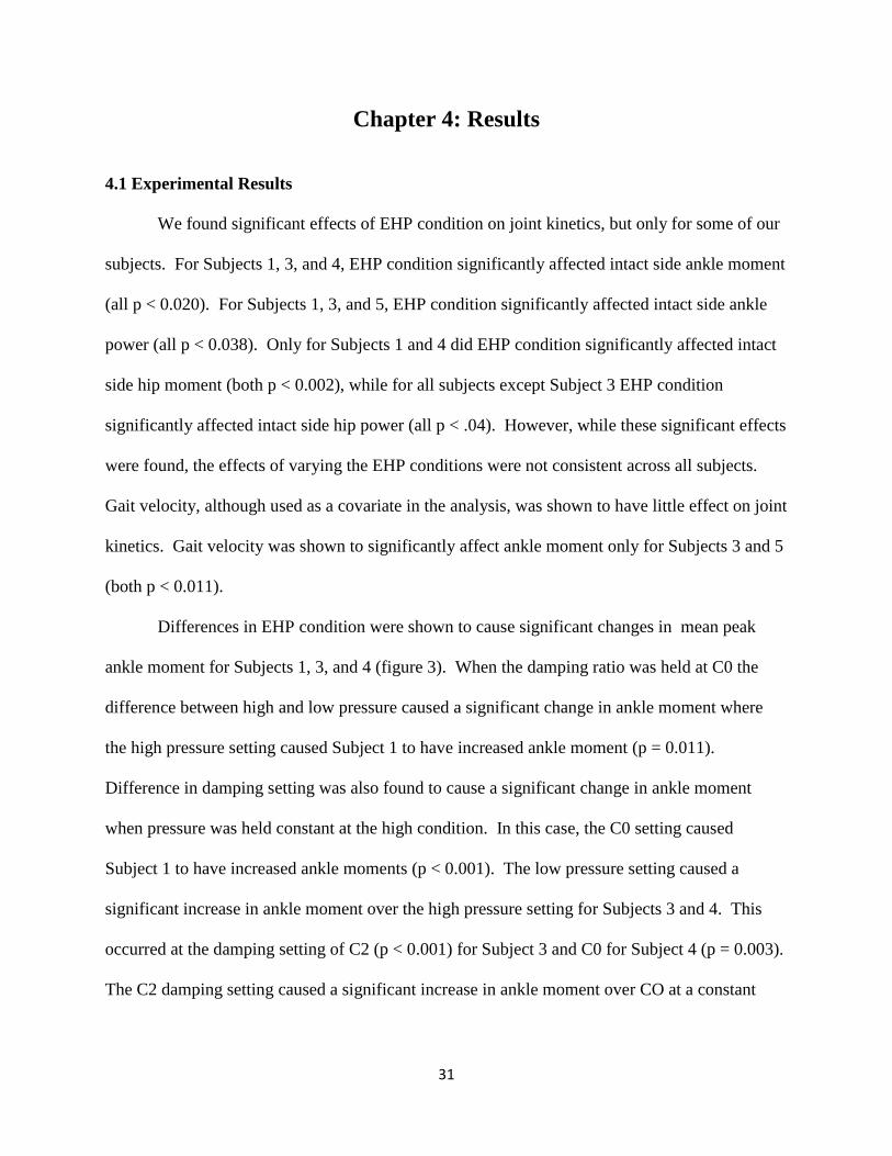
4.1 Experimental Results
We found significant effects of EHP condition on joint kinetics, but only for some of our
subjects. For Subjects 1, 3, and 4, EHP condition significantly affected intact side ankle moment
(all p < 0.020). For Subjects 1, 3, and 5, EHP condition significantly affected intact side ankle
power (all p < 0.038). Only for Subjects 1 and 4 did EHP condition significantly affected intact
side hip moment (both p < 0.002), while for all subjects except Subject 3 EHP condition
significantly affected intact side hip power (all p < .04). However, while these significant effects
were found, the effects of varying the EHP conditions were not consistent across all subjects.
Gait velocity, although used as a covariate in the analysis, was shown to have little effect on joint
kinetics. Gait velocity was shown to significantly affect ankle moment only for Subjects 3 and 5
(both p < 0.011).
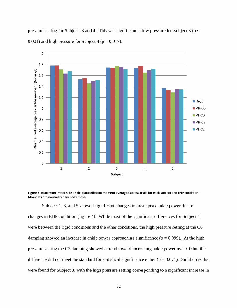
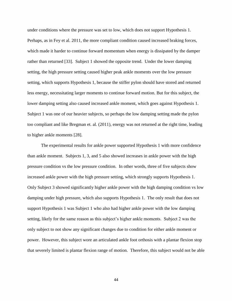
Differences in EHP condition were shown to cause significant changes in mean peak
ankle moment for Subjects 1, 3, and 4 (figure 3). When the damping ratio was held at C0 the
difference between high and low pressure caused a significant change in ankle moment where
the high pressure setting caused Subject 1 to have increased ankle moment (p = 0.011).
Difference in damping setting was also found to cause a significant change in ankle moment
when pressure was held constant at the high condition. In this case, the C0 setting caused
Subject 1 to have increased ankle moments (p < 0.001). The low pressure setting caused a
significant increase in ankle moment over the high pressure setting for Subjects 3 and 4. This
occurred at the damping setting of C2 (p < 0.001) for Subject 3 and C0 for Subject 4 (p = 0.003).
The C2 damping setting caused a significant increase in ankle moment over CO at a constant
32
pressure setting for Subjects 3 and 4. This was significant at low pressure for Subject 3 (p <
0.001) and high pressure for Subject 4 (p = 0.017).
Figure 3: Maximum intact-side ankle plantarflexion moment averaged across trials for each subject and EHP condition. Moments are normalized by body mass.
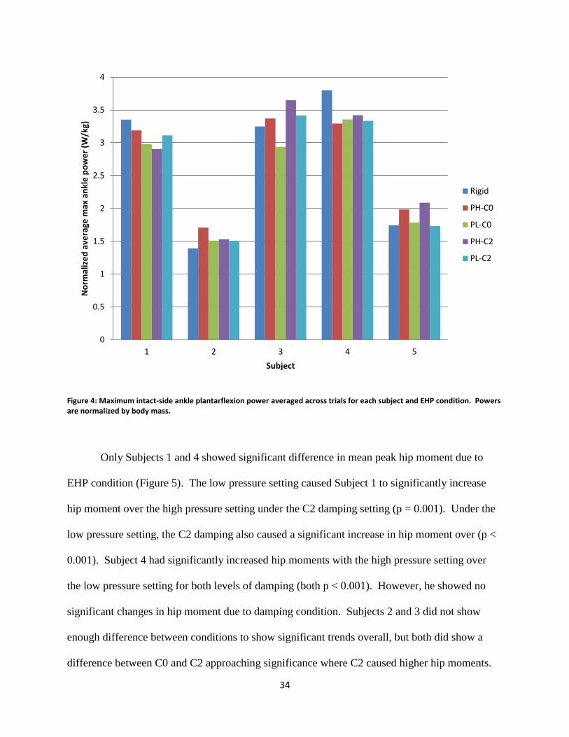
Subjects 1, 3, and 5 showed significant changes in mean peak ankle power due to
changes in EHP condition (figure 4). While most of the significant differences for Subject 1
were between the rigid conditions and the other conditions, the high pressure setting at the C0
damping showed an increase in ankle power approaching significance (p = 0.099). At the high
pressure setting the C2 damping showed a trend toward increasing ankle power over C0 but this
difference did not meet the standard for statistical significance either (p = 0.071). Similar results
were found for Subject 3, with the high pressure setting corresponding to a significant increase in
0
0.2
0.4
0.6
0.8
1
1.2
1.4
1.6
1.8
2
1 2 3 4 5
No
rmal
ize
d a
vera
ge m
ax a
nkl
e m
om
en
t (N
-m/k
g)
Subject
Rigid
PH-C0
PL-C0
PH-C2
PL-C2
33
ankle power under both damping conditions (both p < 0.027). The C2 damping setting also
caused Subject 3 to exhibit increased ankle power over the C0 setting for both pressure
conditions, but only the differences with the high pressure setting was significant (p = 0.037).
The high pressure setting also caused Subject 5 to significantly increase ankle power over the
low pressure setting for both damping conditions (both p < 0.046). However, Subject 5 showed
no significant changes in ankle power due to damping condition. Subject 4 also showed
significant differences in ankle power due to condition, but these differences were all between
rigid and the other conditions, where the rigid condition was associated with higher ankle power
over all other conditions (all p < 0.04). However, this was not enough to show a significant
difference overall among EHP conditions.
34
Figure 4: Maximum intact-side ankle plantarflexion power averaged across trials for each subject and EHP condition. Powers are normalized by body mass.
Only Subjects 1 and 4 showed significant difference in mean peak hip moment due to
EHP condition (Figure 5). The low pressure setting caused Subject 1 to significantly increase
hip moment over the high pressure setting under the C2 damping setting (p = 0.001). Under the
low pressure setting, the C2 damping also caused a significant increase in hip moment over (p <
0.001). Subject 4 had significantly increased hip moments with the high pressure setting over
the low pressure setting for both levels of damping (both p < 0.001). However, he showed no
significant changes in hip moment due to damping condition. Subjects 2 and 3 did not show
enough difference between conditions to show significant trends overall, but both did show a
difference between C0 and C2 approaching significance where C2 caused higher hip moments.
0
0.5
1
1.5
2
2.5
3
3.5
4
1 2 3 4 5
No
rmal
ize
d a
vera
ge m
ax a
nkl
e p
ow
er
(W/k
g)
Subject
Rigid
PH-C0
PL-C0
PH-C2
PL-C2
35
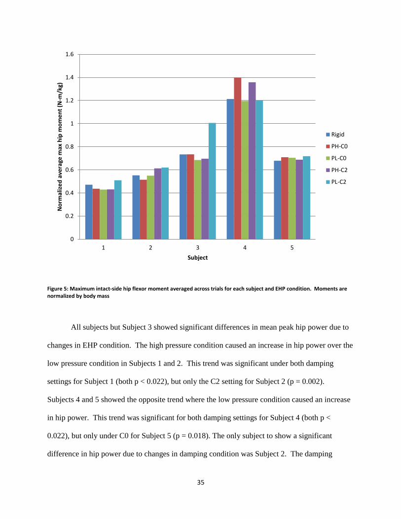
Figure 5: Maximum intact-side hip flexor moment averaged across trials for each subject and EHP condition. Moments are normalized by body mass
All subjects but Subject 3 showed significant differences in mean peak hip power due to
changes in EHP condition. The high pressure condition caused an increase in hip power over the
low pressure condition in Subjects 1 and 2. This trend was significant under both damping
settings for Subject 1 (both p < 0.022), but only the C2 setting for Subject 2 (p = 0.002).
Subjects 4 and 5 showed the opposite trend where the low pressure condition caused an increase
in hip power. This trend was significant for both damping settings for Subject 4 (both p <
0.022), but only under C0 for Subject 5 (p = 0.018). The only subject to show a significant
difference in hip power due to changes in damping condition was Subject 2. The damping
0
0.2
0.4
0.6
0.8
1
1.2
1.4
1.6
1 2 3 4 5
No
rmal
ize
d a
vera
ge m
ax h
ip m
om
en
t (N
-m/k
g)
Subject
Rigid
PH-C0
PL-C0
PH-C2
PL-C2
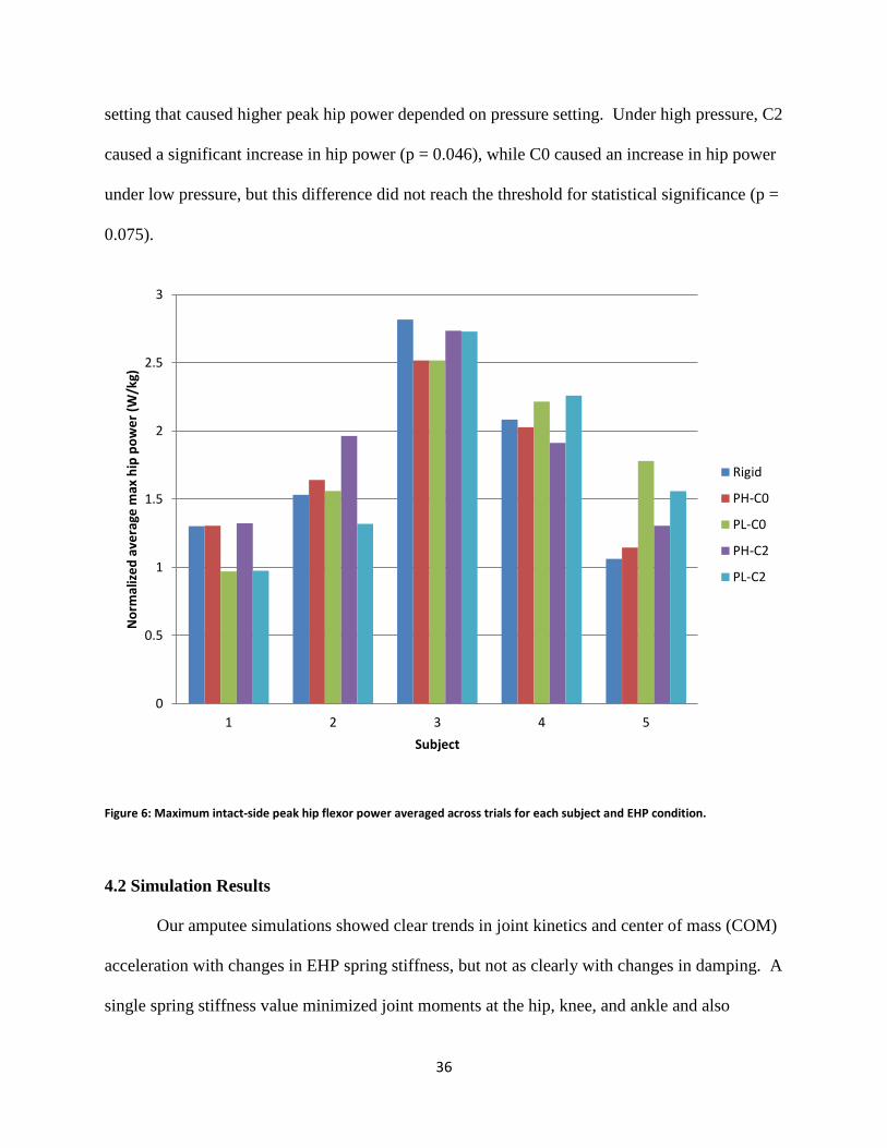
36
setting that caused higher peak hip power depended on pressure setting. Under high pressure, C2
caused a significant increase in hip power (p = 0.046), while C0 caused an increase in hip power
under low pressure, but this difference did not reach the threshold for statistical significance (p =
0.075).
Figure 6: Maximum intact-side peak hip flexor power averaged across trials for each subject and EHP condition.
4.2 Simulation Results
Our amputee simulations showed clear trends in joint kinetics and center of mass (COM)
acceleration with changes in EHP spring stiffness, but not as clearly with changes in damping. A
single spring stiffness value minimized joint moments at the hip, knee, and ankle and also
0
0.5
1
1.5
2
2.5
3
1 2 3 4 5
No
rmal
ize
d a
vera
ge m
ax h
ip p
ow
er
(W/k
g)
Subject
Rigid
PH-C0
PL-C0
PH-C2
PL-C2
37
minimized COM acceleration and ankle power across all levels of damping. Knee power was
minimized by a different spring stiffness across all levels of damping. One spring stiffness
produced consistently low hip powers compared to the other stiffness settings, but no spring
stiffness produced a hip power that was consistently the minimum. Differences in damping
caused noticeable trends in hip moment and power and in COM acceleration, but only at the
lowest spring stiffness. No apparent trends due to damping condition appeared in any of the
other joint measures.
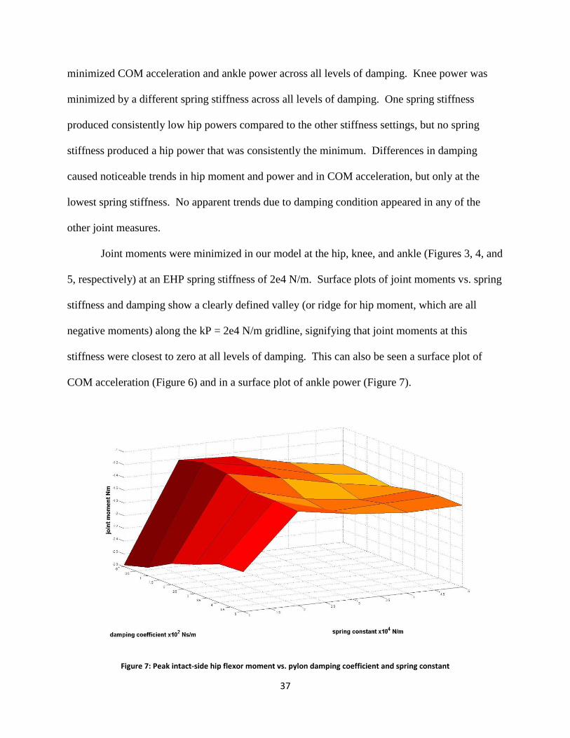
Joint moments were minimized in our model at the hip, knee, and ankle (Figures 3, 4, and
5, respectively) at an EHP spring stiffness of 2e4 N/m. Surface plots of joint moments vs. spring
stiffness and damping show a clearly defined valley (or ridge for hip moment, which are all
negative moments) along the kP = 2e4 N/m gridline, signifying that joint moments at this
stiffness were closest to zero at all levels of damping. This can also be seen a surface plot of
COM acceleration (Figure 6) and in a surface plot of ankle power (Figure 7).
Figure 7: Peak intact-side hip flexor moment vs. pylon damping coefficient and spring constant
38
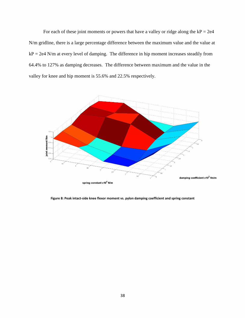
For each of these joint moments or powers that have a valley or ridge along the kP = 2e4
N/m gridline, there is a large percentage difference between the maximum value and the value at
kP = 2e4 N/m at every level of damping. The difference in hip moment increases steadily from
64.4% to 127% as damping decreases. The difference between maximum and the value in the
valley for knee and hip moment is 55.6% and 22.5% respectively.
Figure 8: Peak intact-side knee flexor moment vs. pylon damping coefficient and spring constant
39
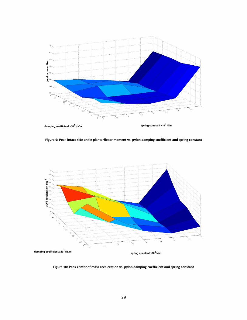
Figure 9: Peak intact-side ankle plantarflexor moment vs. pylon damping coefficient and spring constant
Figure 10: Peak center of mass acceleration vs. pylon damping coefficient and spring constant
40
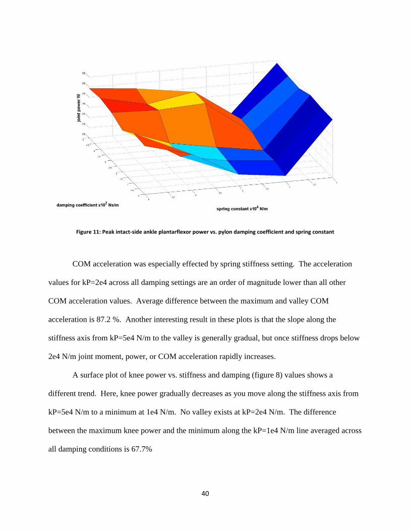
Figure 11: Peak intact-side ankle plantarflexor power vs. pylon damping coefficient and spring constant
COM acceleration was especially effected by spring stiffness setting. The acceleration
values for kP=2e4 across all damping settings are an order of magnitude lower than all other
COM acceleration values. Average difference between the maximum and valley COM
acceleration is 87.2 %. Another interesting result in these plots is that the slope along the
stiffness axis from kP=5e4 N/m to the valley is generally gradual, but once stiffness drops below
2e4 N/m joint moment, power, or COM acceleration rapidly increases.
A surface plot of knee power vs. stiffness and damping (figure 8) values shows a
different trend. Here, knee power gradually decreases as you move along the stiffness axis from
kP=5e4 N/m to a minimum at 1e4 N/m. No valley exists at kP=2e4 N/m. The difference
between the maximum knee power and the minimum along the kP=1e4 N/m line averaged across
all damping conditions is 67.7%
41
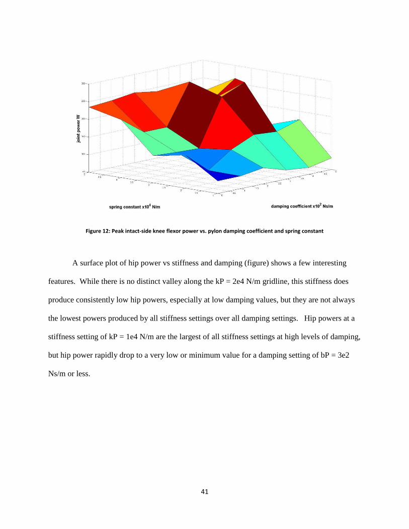
Figure 12: Peak intact-side knee flexor power vs. pylon damping coefficient and spring constant
A surface plot of hip power vs stiffness and damping (figure) shows a few interesting
features. While there is no distinct valley along the kP = 2e4 N/m gridline, this stiffness does
produce consistently low hip powers, especially at low damping values, but they are not always
the lowest powers produced by all stiffness settings over all damping settings. Hip powers at a
stiffness setting of kP = 1e4 N/m are the largest of all stiffness settings at high levels of damping,
but hip power rapidly drop to a very low or minimum value for a damping setting of bP = 3e2
Ns/m or less.

42
Figure 13: Peak intact-side hip flexor power vs. pylon damping coefficient and spring constant
Noticeably apparent trends due to changes in damping condition are only shown in hip
moment, hip power, and COM acceleration, but only at the lowest stiffness of 1e4 N/m. Hip
moment and power steadily decrease as damping increases. The differences between the
maximum moment and power at 0 Ns/m and minimum at 5 Ns/m are 27.3% and 69.9%,
respectively. COM acceleration increases with increasing damping where the difference
between the maximum and minimum acceleration is 75.9%
43
Chapter 5: Discussion
This thesis presents several novel contributions to the study of amputee gait. It was the
first study to examine amputee gait with a shock absorbing pylon containing both a spring and
damper in parallel. Almost all other studies examining varying prosthesis characteristics consider
only stiffness characteristics, but when considering energy harvesting, a damper is necessary as it
serves as a means to purposefully remove energy from the gait cycle that cannot be recovered,
which simulates energy harvesting. This is also one of the first studies of its kind to compare
experiments using live subjects with a complementary modeling study of the same thing. Many
other studies of amputee gait either use just live subjects or just a computer simulation, but doing
both allowed us to test conditions outside what we were able to test with live subjects. The
simulations also add confidence to our experimental findings, as amputee studies sometimes
suffer from low subject numbers. Often it is hard to find individual modeling and experimental
studies of amputee gait that examine the exact same hypotheses. Lastly, we studied the effects of
a pylon-type energy harvester for amputees. This is a product that does not exist in the present
clinical world, yet has much potential to provide benefits to amputees that other devices cannot
provide. But before a device like this can be developed and released for clinical use, we must
know how it will affect the end user. Our results can lead to a refined design that might one day
be used by amputees to provide power to advanced prosthetics.
The experimental data generally supported Hypothesis 1, but this was not the case for
every subject tested. Subjects 3 and 4 showed significant increases in ankle moment under
conditions where the damper was set to the higher damping setting, C2. This directly supports
Hypothesis 1. When the damper removed more energy at heel strike, these subjects compensated
with increased ankle torque. On the other hand, these subject also showed higher ankle moments
44
under conditions where the pressure was set to low, which does not support Hypothesis 1.
Perhaps, as in Fey et al. 2011, the more compliant condition caused increased braking forces,
which made it harder to continue forward momentum when energy is dissipated by the damper
rather than returned [33]. Subject 1 showed the opposite trend. Under the lower damping
setting, the high pressure setting caused higher peak ankle moments over the low pressure
setting, which supports Hypothesis 1, because the stiffer pylon should have stored and returned
less energy, necessitating larger moments to continue forward motion. But for this subject, the
lower damping setting also caused increased ankle moment, which goes against Hypothesis 1.
Subject 1 was one of our heavier subjects, so perhaps the low damping setting made the pylon
too compliant and like Bregman et. al. (2011), energy was not returned at the right time, leading
to higher ankle moments [28].
The experimental results for ankle power supported Hypothesis 1 with more confidence
than ankle moment. Subjects 1, 3, and 5 also showed increases in ankle power with the high
pressure condition vs the low pressure condition. In other words, three of five subjects show
increased ankle power with the high pressure setting, which strongly supports Hypothesis 1.
Only Subject 3 showed significantly higher ankle power with the high damping condition vs low
damping under high pressure, which also supports Hypothesis 1. The only result that does not
support Hypothesis 1 was Subject 1 who also had higher ankle power with the low damping
setting, likely for the same reason as this subject’s higher ankle moments. Subject 2 was the
only subject to not show any significant changes due to condition for either ankle moment or
power. However, this subject wore an articulated ankle foot orthosis with a plantar flexion stop
that severely limited is plantar flexion range of motion. Therefore, this subject would not be able
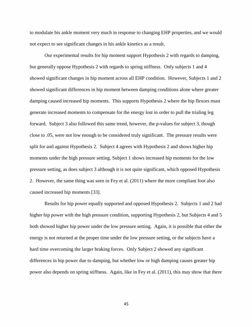
45
to modulate his ankle moment very much in response to changing EHP properties, and we would
not expect to see significant changes in his ankle kinetics as a result.
Our experimental results for hip moment support Hypothesis 2 with regards to damping,
but generally oppose Hypothesis 2 with regards to spring stiffness. Only subjects 1 and 4
showed significant changes in hip moment across all EHP condition. However, Subjects 1 and 2
showed significant differences in hip moment between damping conditions alone where greater
damping caused increased hip moments. This supports Hypothesis 2 where the hip flexors must
generate increased moments to compensate for the energy lost in order to pull the trialing leg
forward. Subject 3 also followed this same trend, however, the p-values for subject 3, though
close to .05, were not low enough to be considered truly significant. The pressure results were
split for and against Hypothesis 2. Subject 4 agrees with Hypothesis 2 and shows higher hip
moments under the high pressure setting. Subject 1 shows increased hip moments for the low
pressure setting, as does subject 3 although it is not quite significant, which opposed Hypothesis
2. However, the same thing was seen in Fey et al. (2011) where the more compliant foot also
caused increased hip moments [33].
Results for hip power equally supported and opposed Hypothesis 2. Subjects 1 and 2 had
higher hip power with the high pressure condition, supporting Hypothesis 2, but Subjects 4 and 5
both showed higher hip power under the low pressure setting. Again, it is possible that either the
energy is not returned at the proper time under the low pressure setting, or the subjects have a
hard time overcoming the larger braking forces. Only Subject 2 showed any significant
differences in hip power due to damping, but whether low or high damping causes greater hip
power also depends on spring stiffness. Again, like in Fey et al. (2011), this may show that there
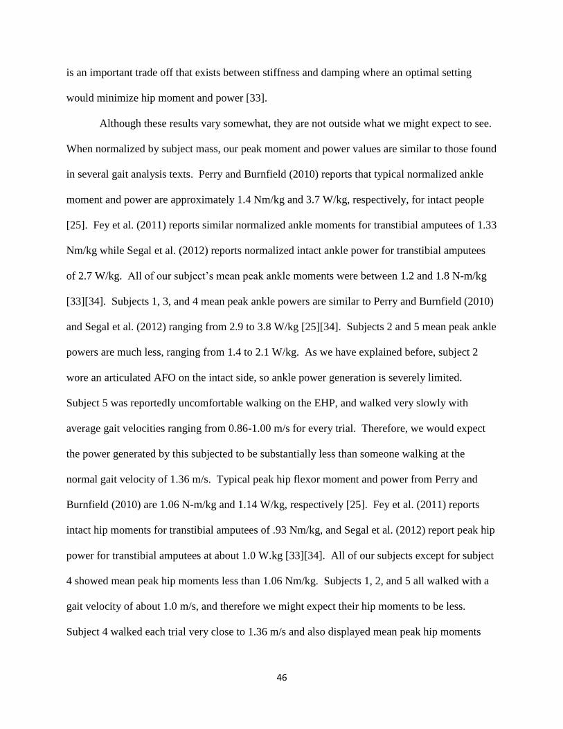
46
is an important trade off that exists between stiffness and damping where an optimal setting
would minimize hip moment and power [33].
Although these results vary somewhat, they are not outside what we might expect to see.
When normalized by subject mass, our peak moment and power values are similar to those found
in several gait analysis texts. Perry and Burnfield (2010) reports that typical normalized ankle
moment and power are approximately 1.4 Nm/kg and 3.7 W/kg, respectively, for intact people
[25]. Fey et al. (2011) reports similar normalized ankle moments for transtibial amputees of 1.33
Nm/kg while Segal et al. (2012) reports normalized intact ankle power for transtibial amputees
of 2.7 W/kg. All of our subject’s mean peak ankle moments were between 1.2 and 1.8 N-m/kg
[33][34]. Subjects 1, 3, and 4 mean peak ankle powers are similar to Perry and Burnfield (2010)
and Segal et al. (2012) ranging from 2.9 to 3.8 W/kg [25][34]. Subjects 2 and 5 mean peak ankle
powers are much less, ranging from 1.4 to 2.1 W/kg. As we have explained before, subject 2
wore an articulated AFO on the intact side, so ankle power generation is severely limited.
Subject 5 was reportedly uncomfortable walking on the EHP, and walked very slowly with
average gait velocities ranging from 0.86-1.00 m/s for every trial. Therefore, we would expect
the power generated by this subjected to be substantially less than someone walking at the
normal gait velocity of 1.36 m/s. Typical peak hip flexor moment and power from Perry and
Burnfield (2010) are 1.06 N-m/kg and 1.14 W/kg, respectively [25]. Fey et al. (2011) reports
intact hip moments for transtibial amputees of .93 Nm/kg, and Segal et al. (2012) report peak hip
power for transtibial amputees at about 1.0 W.kg [33][34]. All of our subjects except for subject
4 showed mean peak hip moments less than 1.06 Nm/kg. Subjects 1, 2, and 5 all walked with a
gait velocity of about 1.0 m/s, and therefore we might expect their hip moments to be less.
Subject 4 walked each trial very close to 1.36 m/s and also displayed mean peak hip moments
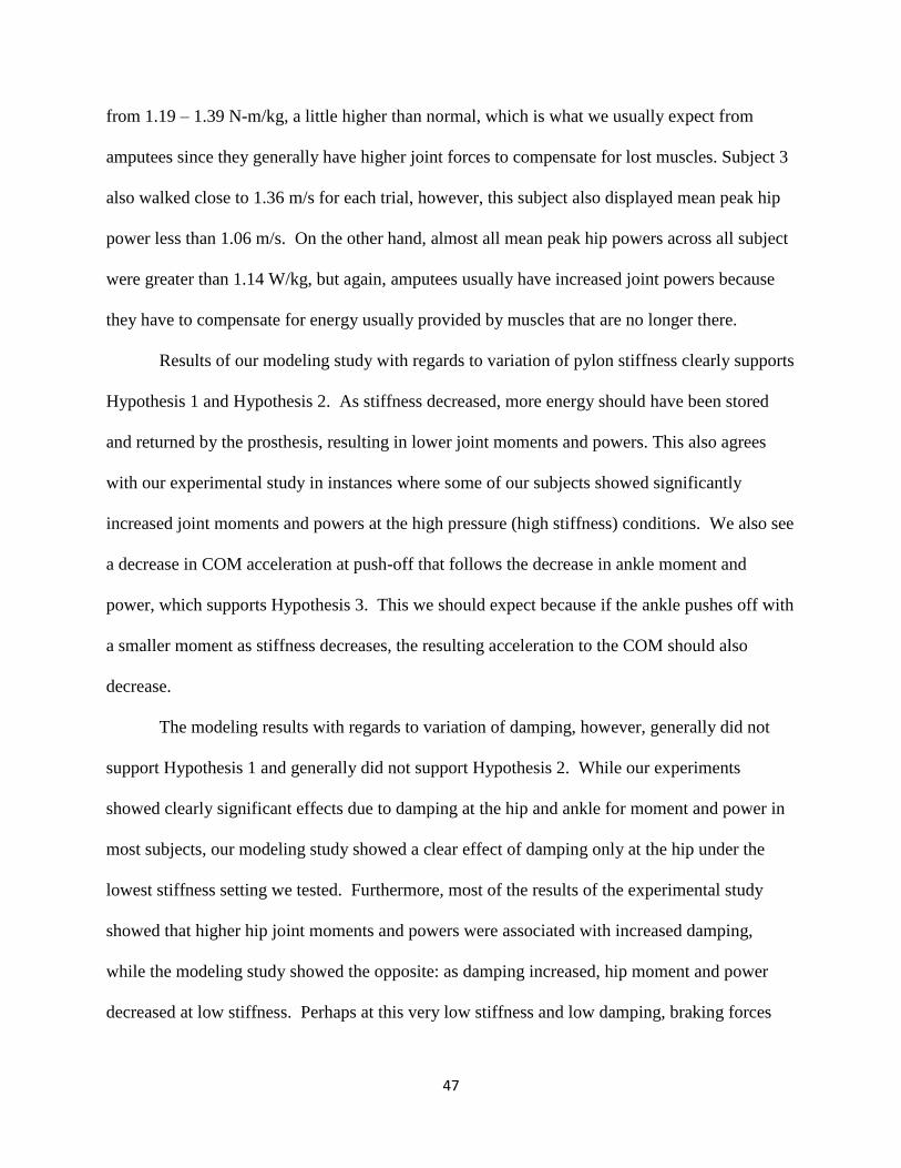
47
from 1.19 – 1.39 N-m/kg, a little higher than normal, which is what we usually expect from
amputees since they generally have higher joint forces to compensate for lost muscles. Subject 3
also walked close to 1.36 m/s for each trial, however, this subject also displayed mean peak hip
power less than 1.06 m/s. On the other hand, almost all mean peak hip powers across all subject
were greater than 1.14 W/kg, but again, amputees usually have increased joint powers because
they have to compensate for energy usually provided by muscles that are no longer there.
Results of our modeling study with regards to variation of pylon stiffness clearly supports
Hypothesis 1 and Hypothesis 2. As stiffness decreased, more energy should have been stored
and returned by the prosthesis, resulting in lower joint moments and powers. This also agrees
with our experimental study in instances where some of our subjects showed significantly
increased joint moments and powers at the high pressure (high stiffness) conditions. We also see
a decrease in COM acceleration at push-off that follows the decrease in ankle moment and
power, which supports Hypothesis 3. This we should expect because if the ankle pushes off with
a smaller moment as stiffness decreases, the resulting acceleration to the COM should also
decrease.
The modeling results with regards to variation of damping, however, generally did not
support Hypothesis 1 and generally did not support Hypothesis 2. While our experiments
showed clearly significant effects due to damping at the hip and ankle for moment and power in
most subjects, our modeling study showed a clear effect of damping only at the hip under the
lowest stiffness setting we tested. Furthermore, most of the results of the experimental study
showed that higher hip joint moments and powers were associated with increased damping,
while the modeling study showed the opposite: as damping increased, hip moment and power
decreased at low stiffness. Perhaps at this very low stiffness and low damping, braking forces
48
are excessive and cause the model to compensate for lost momentum by pulling the trailing leg
forward with greater force.
COM acceleration did increase with damping at the lowest spring stiffness which
supports Hypothesis 3 and suggests that as more energy was taken out of the gait cycle, the
model had to compensate with higher forces to accelerate the COM over the stance leg and
continue forward momentum. However, this increase in COM acceleration did not come with a
corresponding increase in ankle moment or power, so it is unclear where it comes from. Perhaps
the model pulled its body forward with increased help from the prosthetic side hip extensors
under these conditions.
Our modeling results also supported Hypothesis 4. While the simulations for all 30 pylon
conditions converged successfully to a realistic walking motion, some combinations of stiffness
and damping caused joint moments and powers that were two or more standard deviations
greater than mean joint moments and powers considered to be normal [41]. This occurred
mostly at the higher levels of stiffness and was especially true at the knee.
Relatively few studies examine effects on the intact leg due to changes in prosthesis
stiffness. The ones that do tend to examine the effects of the stiffness of prosthetic feet and
ankles. Very few papers look at the stiffness of the pylon. Gard and Konz (2003) did examine
the effects of varying the stiffness of a shock absorbing pylon on amputee gait. As in the
experimental component of the present study, the authors reported results that were inconsistent
across subjects. There were virtually no significant changes in spatiotemporal parameters or
GRF parameters, with the exception of a significant reduction of the GRF force transient at heel
strike with the shock absorbing pylon as opposed to without [30]. Fey et al. (2011) studied the
effects prosthetic foot stiffness on amputee gait. They found similar normalized peak ankle and
49
hip moments compared to our results of about 1.33 Nm/kg and .93 Nm/kg, respectively.
However, they did not find significant differences in joint moments or powers near intact leg
push off across prosthetic foot stiffnesses as we have. On the other hand, they did find
significant difference in hip moment at loading response and in knee moment near 40% of the
gait cycle. Knee moment was reduced and hip moment increased with decreasing stiffness [33].
Segal et al. (2012) studied the effects of controlled energy storage and return (CESR) feet as
opposed to a conventional prosthetic foot on amputee gait and examined the intact side kinetics.
In this study, the CESR foot would represent a more compliant prosthesis condition. They found
intact peak ankle power was 17% lower with the CESR foot opposed to the conventional foot, a
finding that is consistent with our experimental and modeling studies in which lower stiffness
was associated with lower ankle power. Intact side hip power, however, was similar between the
CESR and conventional feet. Similarly, no significant increases were found in knee power at
intact side push off, but they did find significant differences in knee power consistent with Fey et
al [34][33].
While some similar studies of prosthesis compliance on the joint kinetics of amputee gait
are consistent with our results, the overall message of this discussion is that results among all the
literature are quite inconsistent, with many studies finding little or no significant difference in
gait parameters with respect to changing prosthesis compliance. Some of our experimental
results and our modeling results support other authors who have shown reduced muscular joint
moments and powers with a less stiff prosthesis, however, this trend was inconsistent across
subjects just as other studies have found. Furthermore, while most studies focus on the spring
stiffness of prosthetic feet, ankles, and pylons, we have also shown that variation of viscous
damping can also have similar effects on joint kinetics. Like spring stiffness, most subjects have
50
increased joint moments and powers when damping is increased, while a few others show the
opposite effect.
Studies of amputee subjects usually only test two or three prosthesis conditions, and the
results are inconsistent across subjects and across the different joints. However, in our modeling
study, where a much wider array of prosthesis conditions were examined, we found one stiffness
that consistently produced low joint kinetics for all joints. It is possible that previous studies
using live subjects, including our own, did not incorporate a large enough window of
adjustability in their variables of interest to find a condition that produced consistently lower
joint kinetics in each subject. We know that amputees vary greatly in their gait, the devices they
use, and the compensatory mechanisms they employ to walk because of the uniqueness of each
one’s amputation; therefore, we should not expect each amputee to react in the same way to
increasing or decreasing compliance in their prosthesis. A wider modeling study that examined
how models of different mass, stature, and structure of the amputated limb react to the same wide
array of prosthesis conditions might shed light on this issue.
The overall purpose of this work was to examine varying stiffness and damping on
amputee gait to determine the effects that an energy harvesting prosthesis would likely have.
Removing an amount energy that would interrupt the gait cycle or induce so much fatigue as to
cause a fall was a major safety concern. Neither our experimental study nor our modeling study
found a combination of stiffness and damping that caused a catastrophic failure of gait, but
inordinately large simulated joint moments and powers were found for some pylon conditions,
which supported Hypothesis 4. Additionally, some of our subjects did take the opportunity to
rest between trials. These types of studies are relatively short in duration to avoid long term
fatigue. A study of continuous daily wear of such devices seems to be the only way to
51
realistically gauge the effects of continual energy harvesting on amputees and how it may lead to
fatigue.
Our experimental study was subject to a number of limitations. The first, and likely most
important limitation, was our small number of subjects. Having only five subjects did not give
us a very representative sample of the amputee community, nor did it give us much statistical
power. With several times as many subjects we may have found that most subjects reacted to the
different EHP conditions in a similar way, and that a few of the subjects we did test were
actually outliers. Although we recruited in a large age bracket of 18 to 65 years old, our subjects
were not evenly distributed over that range. The young (18 – 25) and middle aged (30 – 50)
population of amputees were not represented at all and may have changed our results. With
more subjects and a more even distribution of ages, it is possible we may have found some gait
differences similar to those that exist between young and elderly able bodied people. A similar
limitation lies in the number of trials we were able to obtain. Our subjects started to tire
noticeably over the course of the study, and consequently we were only able to obtain three or
four usable trials per EHP condition for each subject. Often, one trial of those collected for one
condition and subject were highly unrepresentative of the others. These were also discarded.
This left us with as few as two usable, but consistent, trials for some subjects and conditions.
This also limited our statistical power. If we were able to collect more trials per condition, we
may have seen more obvious trends within subjects and would have had greater statistical power
in our analysis. Another limitation was that we were not able to test a wide array of conditions.
As stated above, amputee gait is highly variable between individuals, so we could not expect
each subject to show significant changes in their gait to the same two stiffness and damping
settings. This low number of conditions is why we also did the modeling study. Finally, we did
52
not consider other sources of damping that may have been significantly different across subjects.
Amputees with longer residual limbs generally have a more securely fitting socket due to the
greater amount of surface area of the residual limb, while amputees with short residual limbs can
have problems with an unsecure fit which allows relative motion between the residual limb and
socket, which is a source of considerable damping.
Our modeling study was also subject to a number of limitations. The model used in the
study was fairly simple. It was a planar model, and lumped the head, arms, trunk, and pelvis
together as one segment, and therefore it could not model some gait mechanisms we know are
present in human gait that allow it to be efficient, such as pelvis rotation and arm swing. If our
model could use these mechanisms, the joint kinetics would also change and different results
may have revealed different trends. Another limitation was also time and the amount of
conditions we could have tested. If time was not a limitation, we could have tested an infinite
number of conditions. We could have lowered the spring stiffness and damping coefficient by
.5e4 and .5e2, or even .1e4 and .1e2, which would have corresponded to 60 and 300 conditions,
respectively. With finer steps between conditions, we may have found the model preferred a
spring stiffness between 3e4 and 2e4 Nm or between 2e4 and 1e4 Nm that produced even lower
joint kinetics than those produced at 2e4 Nm. We were also not able to test models of different
statures and masses. If we were able to run another set of simulations for all the of the EHP
conditions we tested, we may have found that a subject of a different height and mass preferred a
stiffer or more complaint spring, or we may have seen damping have a more significant effect as
it did in our experimental study. This would have allowed us to better explain some of the
variability in our experimental study.
53
In conclusion, variation of the stiffness and damping properties of an energy harvesting
pylon for use in lower limb prostheses did have significant effects on intact side hip and ankle
joint kinetics at push off in most subjects. Some subjects were consistent with our hypotheses
that when more energy was removed from the gait cycle by means of a damper, or when the
spring stores and returns less energy, ankle and hip kinetics were higher to compensate for lost
energy. Some of our subjects and our model also were consistent with other studies that showed
that increased stiffness caused increased intact side joint kinetics at push off. However, overall,
the results of our experiments were somewhat inconsistent. This was one of the first studies to
examine the effects of a prosthesis that incorporated a spring and damper in parallel on amputee
gait. Our modeling study suggests that experiments with live subjects be done with a much
wider array of conditions to accommodate the considerable variability among amputees. All
subjects and our model were able to walk without greatly abnormal kinetics for some
combinations of stiffness and damping, and this suggest that an energy harvesting pylon would
be a viable means of energy scavenging over a range of stiffnesses and damping that can be
tuned to the user to minimize effort while still harvesting energy.
54
Bibliography
[1]A. B. Wilson, “Limb Prosthetics,” Artificial Limbs, vol. 14, no. 1, pp. 1–52, Spring 1970.
[2]H. Celik, “PREDICTIVE GAIT SIMULATIONS FOR INVESTIGATION OF
MUSCULOSKELETAL STRUCTURE AND LOCOMOTOR FUNCTION,” The Pennsylvania
State University, 2014.
[3]S. L. Delp, F. C. Anderson, A. S. Arnold, P. Loan, A. Habib, C. T. John, E. Guendelman, and
D. G. Thelen, “OpenSim: open-source software to create and analyze dynamic simulations of
movement,” IEEE Trans Biomed Eng, vol. 54, no. 11, pp. 1940–1950, Nov. 2007.
[4]B. J. Hafner, J. E. Sanders, J. Czerniecki, and J. Fergason, “Energy storage and return
prostheses: does patient perception correlate with biomechanical analysis?,” Clin Biomech
(Bristol, Avon), vol. 17, no. 5, pp. 325–344, Jun. 2002.
[5]L. A. Miller and D. S. Childress, “Problems associated with the use of inverse dynamics in
prosthetic applications: An example using a polycentric prosthetic knee,” Robotica, vol. 23, no.
03, pp. 329–335, May 2005.
[6]C. M. O’Connor, S. K. Thorpe, M. J. O’Malley, and C. L. Vaughan, “Automatic detection of
gait events using kinematic data,” Gait Posture, vol. 25, no. 3, pp. 469–474, Mar. 2007.
[7]B. J. South, N. P. Fey, G. Bosker, and R. R. Neptune, “Manufacture of energy storage and
return prosthetic feet using selective laser sintering,” J Biomech Eng, vol. 132, no. 1, p. 015001,
Jan. 2010.
[8]“Lower Limb Prosthetic Devices | Just another UMW Blogs weblog.” [Online].
Available:http://prosthetics.umwblogs.org/. [Accessed: 05-Jul-2015].
[9]P. Allard, F. Trudeau, F. Prince, J. Dansereau, H. Labelle, and M. Duhaime, “Modelling and
gait evaluation of asymmetrical-keel foot prosthesis,” Med Biol Eng Comput, vol. 33, no. 1, pp.
2–7, Jan. 1995.
[10]G. Z. Y. C. Dundass, “Initial Biomechanical Analysis and Modeling of Transfemoral
Amputee Gait,” JPO: Journal of Prosthetics and Orthotics, vol. 15, no. 1, pp. 20–26, 2002.
[11]L. Fang, X. Jia, and R. Wang, “Modeling and simulation of muscle forces of trans-tibial
amputee to study effect of prosthetic alignment,” Clin Biomech (Bristol, Avon), vol. 22, no. 10,
pp. 1125–1131, Dec. 2007.
55
[12]S. H. Collins and A. D. Kuo, “Recycling energy to restore impaired ankle function during
human walking,” PLoS ONE, vol. 5, no. 2, p. e9307, 2010.
[13]J. M. Donelan, Q. Li, V. Naing, J. A. Hoffer, D. J. Weber, and A. D. Kuo, “Biomechanical
Energy Harvesting: Generating Electricity During Walking with Minimal User Effort,”Science,
vol. 319, no. 5864, pp. 807–810, 2008.
[14]N. S. Shenck and J. A. Paradiso, “Energy scavenging with shoe-mounted
piezoelectrics,” IEEE Micro, vol. 21, no. 3, pp. 30–42, May 2001.
[15]R. Riemer and A. Shapiro, “Biomechanical energy harvesting from human motion: theory,
state of the art, design guidelines, and future directions,” Journal of NeuroEngineering and
Rehabilitation, vol. 8, no. 1, p. 22, Apr. 2011.
[16]A. D. Kuo, “Harvesting Energy by Improving the Economy of Human Walking,” Science,
vol. 309, no. 5741, pp. 1686–1687, 2005.
[17]T. Starner and J. A. Paradiso, “Human Generated Power for Mobile Electronics,” inLow
Power Electronics Design, 2004, pp. 1–35.
[18]B. S. Farber and J. S. Jacobson, “An above-knee prosthesis with a system of energy
recovery: a technical note,” J Rehabil Res Dev, vol. 32, no. 4, pp. 337–348, Nov. 1995.
[19]A. K. Silverman and R. R. Neptune, “Muscle and prosthesis contributions to amputee
walking mechanics: a modeling study,” J Biomech, vol. 45, no. 13, pp. 2271–2278, Aug. 2012.
[20]N. P. Fey, G. K. Klute, and R. R. Neptune, “Optimization of Prosthetic Foot Stiffness to
Reduce Metabolic Cost and Intact Knee Loading During Below-Knee Amputee Walking: A
Theoretical Study,” J Biomech Eng, vol. 134, no. 11, pp. 1110051–11100510, Nov. 2012.
[21]G. K. K. Nicholas P Fey, “ASB Journal of Biomechanics Award – Simulation predictions of
prosthetic foot and muscle function in response to altered foot stiffness during below-knee
amputee gait,” 2012.
[22]S. J. Piazza, “Muscle-driven forward dynamic simulations for the study of normal and
pathological gait,” J Neuroengineering Rehabil, vol. 3, p. 5, Mar. 2006.
[23]A. Hreljac and R. N. Marshall, “Algorithms to determine event timing during normal
walking using kinematic data,” J Biomech, vol. 33, no. 6, pp. 783–786, Jun. 2000.
56
[24]H. M. Herr and A. M. Grabowski, “Bionic ankle-foot prosthesis normalizes walking gait for
persons with leg amputation,” Proc. Biol. Sci., vol. 279, no. 1728, pp. 457–464, Feb. 2012.
[25]J. Perry and J. M. Burnfield, Gait Analysis: Normal and Pathological Function, 2nd ed.
Slack Inc., 2010.
[26]J. A. Zeni, J. G. Richards, and J. S. Higginson, “Two simple methods for determining gait
events during treadmill and overground walking using kinematic data,” Gait Posture, vol. 27, no.
4, pp. 710–714, May 2008.
[27]J. Kymissis, C. Kendall, J. Paradiso, and N. Gershenfeld, “Parasitic power harvesting in
shoes,” in Proceedings of the Second International Symposium on Wearable Computers,
Pittsburgh, PA, USA, 1998, pp. 132–139.
[28]D. J. J. Bregman, M. M. van der Krogt, V. de Groot, J. Harlaar, M. Wisse, and S. H. Collins,
“The effect of ankle foot orthosis stiffness on the energy cost of walking: a simulation
study,” Clin Biomech (Bristol, Avon), vol. 26, no. 9, pp. 955–961, Nov. 2011.
[29]P. Brugger and H.-B. Schmiedmayer, “Simulating Prosthetic Gait - Lessons to Learn,” Proc.
Appl. Math. Mech., vol. 3, no. 1, pp. 64–67, Dec. 2003.
[30]S. A. Gard and R. J. Konz, “The effect of a shock-absorbing pylon on the gait of persons
with unilateral transtibial amputation,” J Rehabil Res Dev, vol. 40, no. 2, pp. 109–124, Mar.–
Apr. 2003.
[31]K. E. Zelik, S. H. Collins, P. G. Adamczyk, A. D. Segal, G. K. Klute, D. C. Morgenroth, M.
E. Hahn, M. S. Orendurff, J. M. Czerniecki, and A. D. Kuo, “Systematic variation of prosthetic
foot spring affects center-of-mass mechanics and metabolic cost during walking,” IEEE Trans
Neural Syst Rehabil Eng, vol. 19, no. 4, pp. 411–419, Aug. 2011.
[32] J. D. Ventura, G. K. Klute, and R. R. Neptune, “The effect of prosthetic ankle energy
storage and return properties on muscle activity in below-knee amputee walking,” Gait &
Posture, vol. 33, no. 2, pp. 220–226, Feb. 2011.
[33]N. P. Fey, G. K. Klute, and R. R. Neptune, “The influence of energy storage and return foot
stiffness on walking mechanics and muscle activity in below-knee amputees,” Clinical
Biomechanics, vol. 26, no. 10, pp. 1025–1032, Dec. 2011.
[34]A. D. Segal, K. E. Zelik, G. K. Klute, D. C. Morgenroth, M. E. Hahn, M. S. Orendurff, P. G.
Adamczyk, S. H. Collins, A. D. Kuo, and J. M. Czerniecki, “The effects of a controlled energy

57
storage and return prototype prosthetic foot on transtibial amputee ambulation,” Hum Mov Sci,
vol. 31, no. 4, pp. 918–931, Aug. 2012.
[35] “C-Leg 4 above knee prosthetic leg — Ottobock.” [Online].
Available:http://www.ottobockus.com/prosthetics/lower-limb-prosthetics/solution-overview/c-
leg-above-knee-system/. [Accessed: 05-Jul-2015].
[36] “Plié® 2.0 MPC Knee Instructions for Use.” Freedom Innovations.
[37] “Power Knee Technical Manual.” Ossur.
[38] “The DEKA arm.” [Online]. Available:http://www.dekaresearch.com/deka_arm.shtml.
[39] Maryann, “Soldiers’ Angels Germany: Army Ranger completes four deployments as
amputee,” Soldiers’ Angels Germany, 05-Jun-2011. [Online].
Available:http://soldiersangelsgermany.blogspot.com/2011/06/army-ranger-completes-four-
deployments.html. [Accessed: 05-Jul-2015].
[40] Fischer, “A Guide to U.S. Military Casualty Statistics: Operation New Dawn, Operation
Iraqi Freedom, and Operation Enduring Freedom,” Congressional Research Service, CRS Report
for Congress RS22452, Feb. 2014.].
[41] Gerald F. Harris, Peter A. Smith, Human Motion Analysis: Current Applications and
Future Directions. 1996.
[42] “Model Based Item: JOINT VELOCITY: Joint Angular Velocity,” C-Motion Wiki
Documentation. [Online]. Available: http://www.c-
motion.com/v3dwiki/index.php?title=Model_Based_Item:_JOINT_VELOCITY:_Joint_Angular
_Velocity.


![Techniques to Assess Balance and Mobility in Lower-Limb Prosthesis … · 2018. 2. 1. · on standard kinematic and kinetic parameters of amputee gait and posture [15, 16]. Additionally,](https://img.pdfslide.us/doc/110x75/61222f77732c1219b4551ab5/techniques-to-assess-balance-and-mobility-in-lower-limb-prosthesis-2018-2-1.jpg)