Embed Size (px)
Citation preview
Altera Monitor ProgramTutorial
For Quartus II 13.0
1 Introduction
This tutorial presents an introduction to the Altera Monitor Program, which can be used to compile, assemble, down-load and debug programs for Altera’s Nios II processor. The tutorial gives step-by-step instructions that illustratethe features of the Monitor Program.
The Monitor Program is a software application which runs on a host PC, and communicates with a Nios II hardwaresystem on an FPGA board. The Monitor Program is compatible with Microsoft Windows operating systems, includ-ing XP, Vista, and Windows 7. It allows the user to assemble/compile a Nios II software application, download theapplication to a Nios II hardware system, and then debug the running application. The Monitor Program providesfeatures that allow a user to:
• Set up a Nios II project that specifies a desired hardware system and software program
• Download the Nios II hardware system onto an FPGA board
• Compile software programs, specified in assembly language or C, and download the resulting machine codeinto the Nios II hardware system
• Disassemble and display the Nios II machine code stored in memory
• Run the Nios II processor, either continuously or by single-stepping instructions
• Examine and modify the contents of Nios II registers
• Examine and modify the contents of memory, as well as memory-mapped registers in I/O devices
• Set breakpoints that stop the execution of a program at a specified address, or when certain conditions are met
• Perform terminal input/output via a JTAG UART component in the Nios II hardware system
• Develop Nios II programs that make use of device driver functions provided through Altera’s Hardware Ab-straction Layer (HAL)
The process of downloading and debugging a Nios II program requires the presence of an FPGA board to implementthe Nios II hardware system. In this tutorial it is assumed that the reader has access to the Altera DE2-115 Develop-ment and Education board, connected to a computer that has Quartus II (version 13.0) and Nios II Embedded DesignSuite (EDS) software installed. Although a reader who does not have access to an FPGA board will not be able toexecute the Monitor Program commands described in the tutorial, it should still be possible to follow the discussion.
Altera Corporation - University ProgramMay 2013
1
ALTERA MONITOR PROGRAM TUTORIAL For Quartus II 13.0
The screen captures in this tutorial were obtained using version 13.0 of the Monitor Program; if other versions ofthe software are used, some of the images may be slightly different.
1.1 Who should use the Monitor Program
The Monitor Program is intended to be used in an educational environment by professors and students. It is notintended for commercial use.
2 Installing the Monitor Program
The Monitor Program is released as part of Altera’s University Program Design Suite (UPDS). Before the UPDS canbe installed on a computer, it is necessary to first install Altera’s Quartus II CAD software (either the Web Edition orSubscription Edition) and the Nios II Embedded Design Suite (EDS). This release (13.0) of the Monitor Program canbe used only with version 13.0 of the Quartus II software and Nios II EDS. This software can be obtained from theDownload Center on Altera’s website at www.altera.com. To locate version 13.0 of the software for downloading,it may be necessary to click on the item All Design Software in the section of the download page labeled Archives.Once the Quartus II software and Nios II EDS are installed, then the Altera UPDS can be installed as follows:
1. Install the Altera UPDS from the University Program section of Altera’s website. It can be found by goingto www.altera.com and clicking on University Program under Training. Once in the University Programsection, use the navigation links on the page to select Educational Materials > Software Tools > Altera MonitorProgram. Then click on the EXE item in the displayed table, which links to an installation program calledaltera_upds_setup.exe. When prompted to Run or Save this file, select Run.
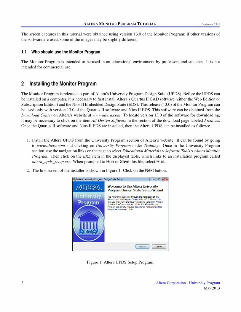
2. The first screen of the installer is shown in Figure 1. Click on the Next button.
Figure 1. Altera UPDS Setup Program.
2 Altera Corporation - University ProgramMay 2013
ALTERA MONITOR PROGRAM TUTORIAL For Quartus II 13.0
3. The installer will display the License Agreement; if you accept the terms of this agreement, then click I Agreeto continue.
4. The installer now displays the root directory where the Altera University Program Design Suite will be in-stalled. Click Next.
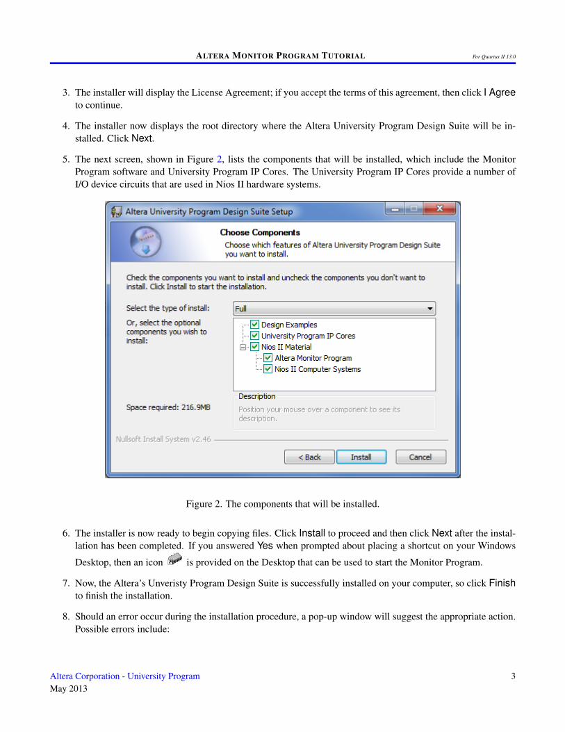
5. The next screen, shown in Figure 2, lists the components that will be installed, which include the MonitorProgram software and University Program IP Cores. The University Program IP Cores provide a number ofI/O device circuits that are used in Nios II hardware systems.
Figure 2. The components that will be installed.
6. The installer is now ready to begin copying files. Click Install to proceed and then click Next after the instal-lation has been completed. If you answered Yes when prompted about placing a shortcut on your Windows
Desktop, then an icon is provided on the Desktop that can be used to start the Monitor Program.
7. Now, the Altera’s Unveristy Program Design Suite is successfully installed on your computer, so click Finishto finish the installation.
8. Should an error occur during the installation procedure, a pop-up window will suggest the appropriate action.Possible errors include:
Altera Corporation - University ProgramMay 2013
3

ALTERA MONITOR PROGRAM TUTORIAL For Quartus II 13.0
• Quartus II software is not installed or the Quartus II version is incorrect (only version 13.0 is supportedby this release of the Monitor Program).
• Nios II EDS software is not installed or the version is incorrect (only version 13.0 is supported).
Note that if the Quartus II software is reinstalled at some future time, then it will be necessary to re-install theMonitor Program at that time.
3 Main Features of the Monitor Program
Each Nios II software application that is developed with the Altera Monitor Program is called a project. The MonitorProgram works on one project at a time and keeps all information for that project in a single directory in the filesystem. The first step is to create a directory to hold the project’s files. To store the design files for this tutorial, wewill use a directory named Monitor_Tutorial. The running example for this tutorial is a simple assembly languageprogram that controls some lights on a DE2-115 board.
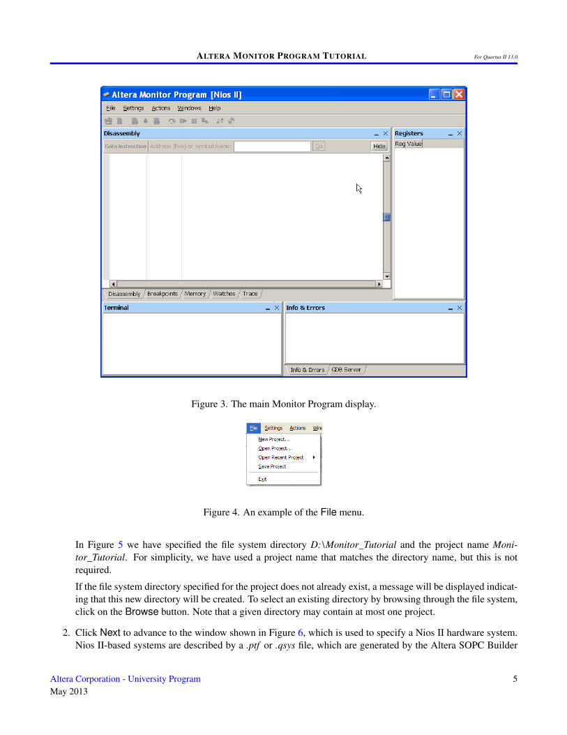
Start the Monitor Program software, either by double-clicking its icon on the Windows Desktop or by accessing theprogram in the Windows Start menu under Altera > University Program > Altera Monitor Program. You shouldsee a display similar to the one in Figure 3. This display consists of several windows that provide access to all of thefeatures of the Monitor Program, which the user selects with the computer mouse. Most of the commands providedby the Monitor Program can be accessed by using a set of menus that are located below the title bar. For example,in Figure 3 clicking the left mouse button on the File command opens the menu shown in Figure 4. Clicking the leftmouse button on the entry Exit exits from the Monitor Program. In most cases, whenever the mouse is used to selectsomething, the left button is used. Hence we will not normally specify which button to press.
For some commands it is necessary to access two or more menus in sequence. We use the convention Menu1 >Menu2 > Item to indicate that to select the desired command the user should first click the mouse button on Menu1,then within this menu click on Menu2, and then within Menu2 click on Item. For example, File > Exit uses themouse to exit from the system. Many commands can alternatively be invoked by clicking on an icon displayed inthe Monitor Program window. To see the command associated with an icon, position the mouse over the icon and atooltip will appear that displays the command name.
It is possible to modify the organization of the Monitor Program display in Figure 3 in many ways. Section 10 showshow to move, resize, close, and open windows within the Monitor Program display.
3.1 Creating a Project
To start working on a Nios II software application we first have to create a new project, as follows:
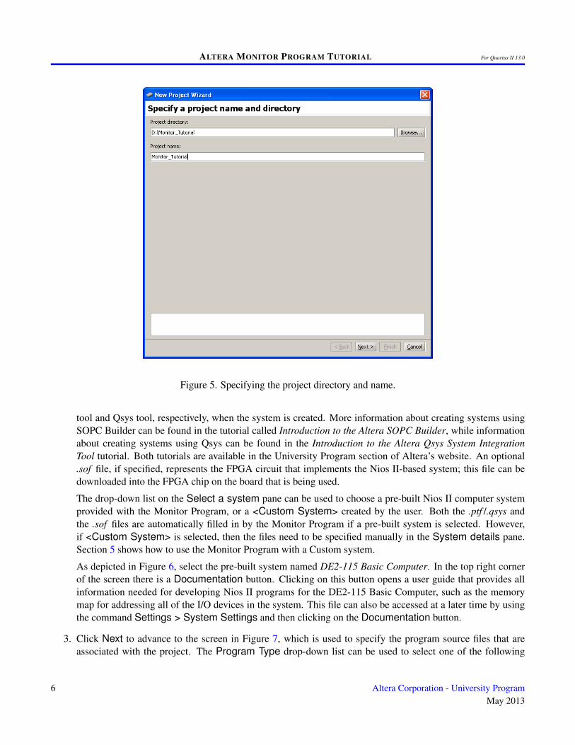
1. Select File > New Project to open the New Project Wizard, which leads to the screen in Figure 5. The Wizardpresents a sequence of screens for defining a new project. Each screen includes a number of dialogs, as wellas a message area at the bottom of the window. The message area is used to display error and informationmessages associated with the dialogs in the window. Double-clicking the mouse on an error message movesthe cursor into the dialog box that contains the source of the error.
4 Altera Corporation - University ProgramMay 2013
ALTERA MONITOR PROGRAM TUTORIAL For Quartus II 13.0
Figure 3. The main Monitor Program display.
Figure 4. An example of the File menu.
In Figure 5 we have specified the file system directory D:\Monitor_Tutorial and the project name Moni-tor_Tutorial. For simplicity, we have used a project name that matches the directory name, but this is notrequired.
If the file system directory specified for the project does not already exist, a message will be displayed indicat-ing that this new directory will be created. To select an existing directory by browsing through the file system,click on the Browse button. Note that a given directory may contain at most one project.
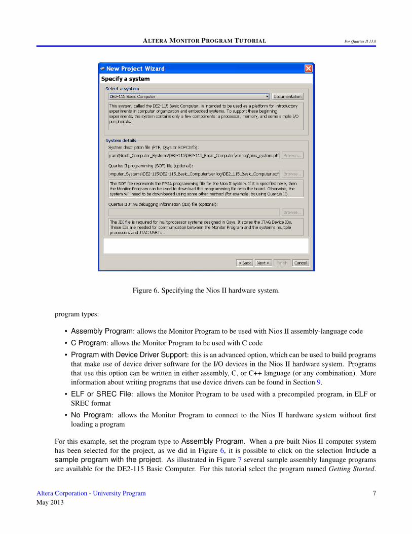
2. Click Next to advance to the window shown in Figure 6, which is used to specify a Nios II hardware system.Nios II-based systems are described by a .ptf or .qsys file, which are generated by the Altera SOPC Builder
Altera Corporation - University ProgramMay 2013
5
ALTERA MONITOR PROGRAM TUTORIAL For Quartus II 13.0
Figure 5. Specifying the project directory and name.
tool and Qsys tool, respectively, when the system is created. More information about creating systems usingSOPC Builder can be found in the tutorial called Introduction to the Altera SOPC Builder, while informationabout creating systems using Qsys can be found in the Introduction to the Altera Qsys System IntegrationTool tutorial. Both tutorials are available in the University Program section of Altera’s website. An optional.sof file, if specified, represents the FPGA circuit that implements the Nios II-based system; this file can bedownloaded into the FPGA chip on the board that is being used.
The drop-down list on the Select a system pane can be used to choose a pre-built Nios II computer systemprovided with the Monitor Program, or a <Custom System> created by the user. Both the .ptf /.qsys andthe .sof files are automatically filled in by the Monitor Program if a pre-built system is selected. However,if <Custom System> is selected, then the files need to be specified manually in the System details pane.Section 5 shows how to use the Monitor Program with a Custom system.
As depicted in Figure 6, select the pre-built system named DE2-115 Basic Computer. In the top right cornerof the screen there is a Documentation button. Clicking on this button opens a user guide that provides allinformation needed for developing Nios II programs for the DE2-115 Basic Computer, such as the memorymap for addressing all of the I/O devices in the system. This file can also be accessed at a later time by usingthe command Settings > System Settings and then clicking on the Documentation button.
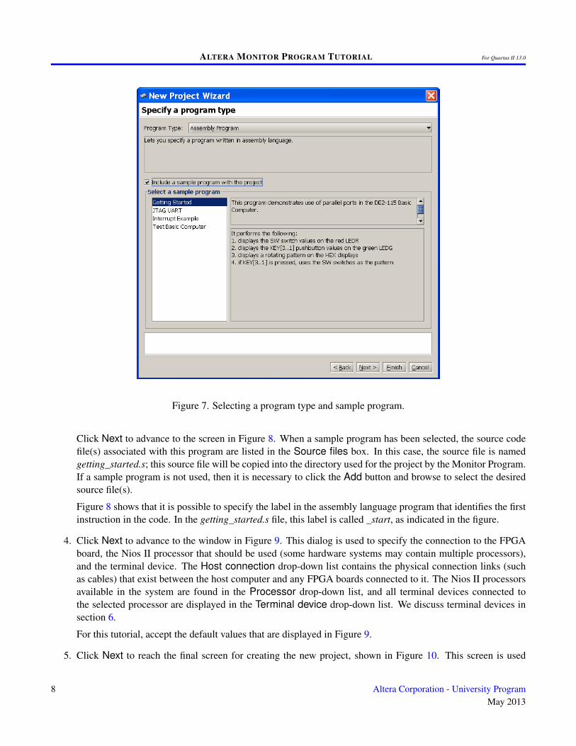
3. Click Next to advance to the screen in Figure 7, which is used to specify the program source files that areassociated with the project. The Program Type drop-down list can be used to select one of the following
6 Altera Corporation - University ProgramMay 2013
ALTERA MONITOR PROGRAM TUTORIAL For Quartus II 13.0
Figure 6. Specifying the Nios II hardware system.
program types:
• Assembly Program: allows the Monitor Program to be used with Nios II assembly-language code
• C Program: allows the Monitor Program to be used with C code
• Program with Device Driver Support: this is an advanced option, which can be used to build programsthat make use of device driver software for the I/O devices in the Nios II hardware system. Programsthat use this option can be written in either assembly, C, or C++ language (or any combination). Moreinformation about writing programs that use device drivers can be found in Section 9.
• ELF or SREC File: allows the Monitor Program to be used with a precompiled program, in ELF orSREC format
• No Program: allows the Monitor Program to connect to the Nios II hardware system without firstloading a program
For this example, set the program type to Assembly Program. When a pre-built Nios II computer systemhas been selected for the project, as we did in Figure 6, it is possible to click on the selection Include asample program with the project. As illustrated in Figure 7 several sample assembly language programsare available for the DE2-115 Basic Computer. For this tutorial select the program named Getting Started.
Altera Corporation - University ProgramMay 2013
7
ALTERA MONITOR PROGRAM TUTORIAL For Quartus II 13.0
Figure 7. Selecting a program type and sample program.
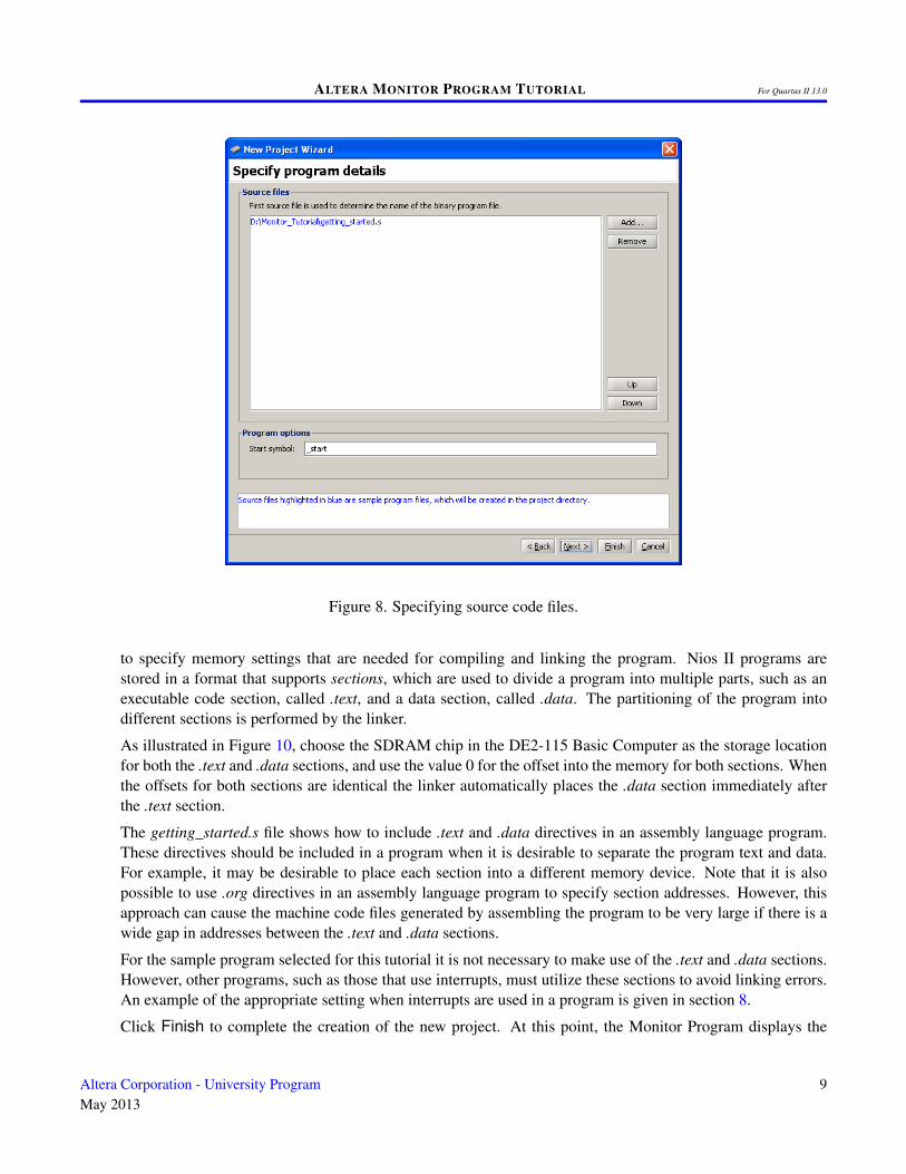
Click Next to advance to the screen in Figure 8. When a sample program has been selected, the source codefile(s) associated with this program are listed in the Source files box. In this case, the source file is namedgetting_started.s; this source file will be copied into the directory used for the project by the Monitor Program.If a sample program is not used, then it is necessary to click the Add button and browse to select the desiredsource file(s).
Figure 8 shows that it is possible to specify the label in the assembly language program that identifies the firstinstruction in the code. In the getting_started.s file, this label is called _start, as indicated in the figure.
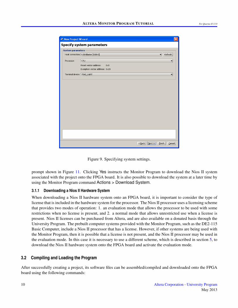
4. Click Next to advance to the window in Figure 9. This dialog is used to specify the connection to the FPGAboard, the Nios II processor that should be used (some hardware systems may contain multiple processors),and the terminal device. The Host connection drop-down list contains the physical connection links (suchas cables) that exist between the host computer and any FPGA boards connected to it. The Nios II processorsavailable in the system are found in the Processor drop-down list, and all terminal devices connected tothe selected processor are displayed in the Terminal device drop-down list. We discuss terminal devices insection 6.
For this tutorial, accept the default values that are displayed in Figure 9.
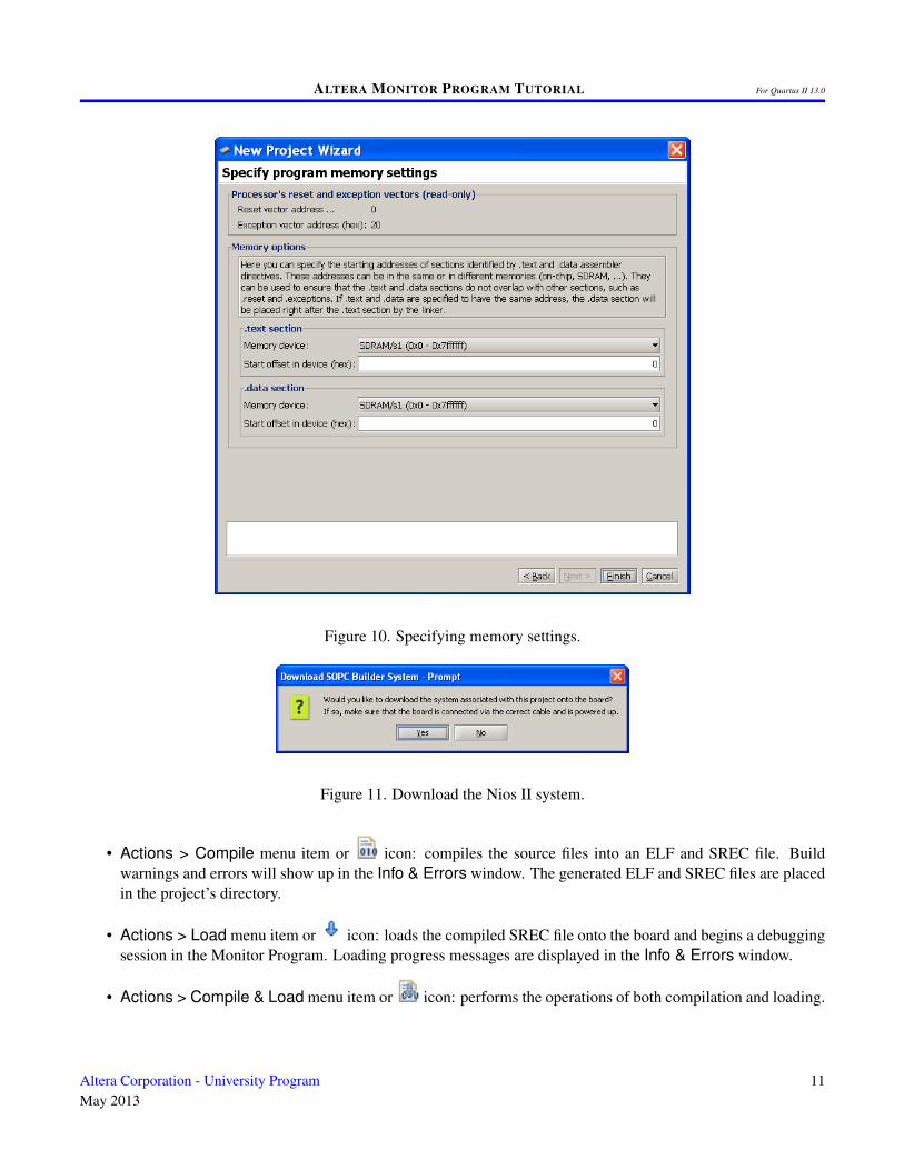
5. Click Next to reach the final screen for creating the new project, shown in Figure 10. This screen is used
8 Altera Corporation - University ProgramMay 2013
ALTERA MONITOR PROGRAM TUTORIAL For Quartus II 13.0
Figure 8. Specifying source code files.
to specify memory settings that are needed for compiling and linking the program. Nios II programs arestored in a format that supports sections, which are used to divide a program into multiple parts, such as anexecutable code section, called .text, and a data section, called .data. The partitioning of the program intodifferent sections is performed by the linker.
As illustrated in Figure 10, choose the SDRAM chip in the DE2-115 Basic Computer as the storage locationfor both the .text and .data sections, and use the value 0 for the offset into the memory for both sections. Whenthe offsets for both sections are identical the linker automatically places the .data section immediately afterthe .text section.
The getting_started.s file shows how to include .text and .data directives in an assembly language program.These directives should be included in a program when it is desirable to separate the program text and data.For example, it may be desirable to place each section into a different memory device. Note that it is alsopossible to use .org directives in an assembly language program to specify section addresses. However, thisapproach can cause the machine code files generated by assembling the program to be very large if there is awide gap in addresses between the .text and .data sections.
For the sample program selected for this tutorial it is not necessary to make use of the .text and .data sections.However, other programs, such as those that use interrupts, must utilize these sections to avoid linking errors.An example of the appropriate setting when interrupts are used in a program is given in section 8.
Click Finish to complete the creation of the new project. At this point, the Monitor Program displays the
Altera Corporation - University ProgramMay 2013
9
ALTERA MONITOR PROGRAM TUTORIAL For Quartus II 13.0
Figure 9. Specifying system settings.
prompt shown in Figure 11. Clicking Yes instructs the Monitor Program to download the Nios II systemassociated with the project onto the FPGA board. It is also possible to download the system at a later time byusing the Monitor Program command Actions > Download System.
3.1.1 Downloading a Nios II Hardware System
When downloading a Nios II hardware system onto an FPGA board, it is important to consider the type oflicense that is included in the hardware system for the processor. The Nios II processor uses a licensing schemethat provides two modes of operation: 1. an evaluation mode that allows the processor to be used with somerestrictions when no license is present, and 2. a normal mode that allows unrestricted use when a license ispresent. Nios II licenses can be purchased from Altera, and are also available on a donated basis through theUniversity Program. The prebuilt computer systems provided with the Monitor Program, such as the DE2-115Basic Computer, include a Nios II processor that has a license. However, if other systems are being used withthe Monitor Program, then it is possible that a license is not present, and the Nios II processor may be used inthe evaluation mode. In this case it is necessary to use a different scheme, which is described in section 5, todownload the Nios II hardware system onto the FPGA board and activate the evaluation mode.
3.2 Compiling and Loading the Program
After successfully creating a project, its software files can be assembled/compiled and downloaded onto the FPGAboard using the following commands:
10 Altera Corporation - University ProgramMay 2013
ALTERA MONITOR PROGRAM TUTORIAL For Quartus II 13.0
Figure 10. Specifying memory settings.
Figure 11. Download the Nios II system.
• Actions > Compile menu item or icon: compiles the source files into an ELF and SREC file. Buildwarnings and errors will show up in the Info & Errors window. The generated ELF and SREC files are placedin the project’s directory.
• Actions > Load menu item or icon: loads the compiled SREC file onto the board and begins a debuggingsession in the Monitor Program. Loading progress messages are displayed in the Info & Errors window.
• Actions > Compile & Load menu item or icon: performs the operations of both compilation and loading.
Altera Corporation - University ProgramMay 2013
11
ALTERA MONITOR PROGRAM TUTORIAL For Quartus II 13.0
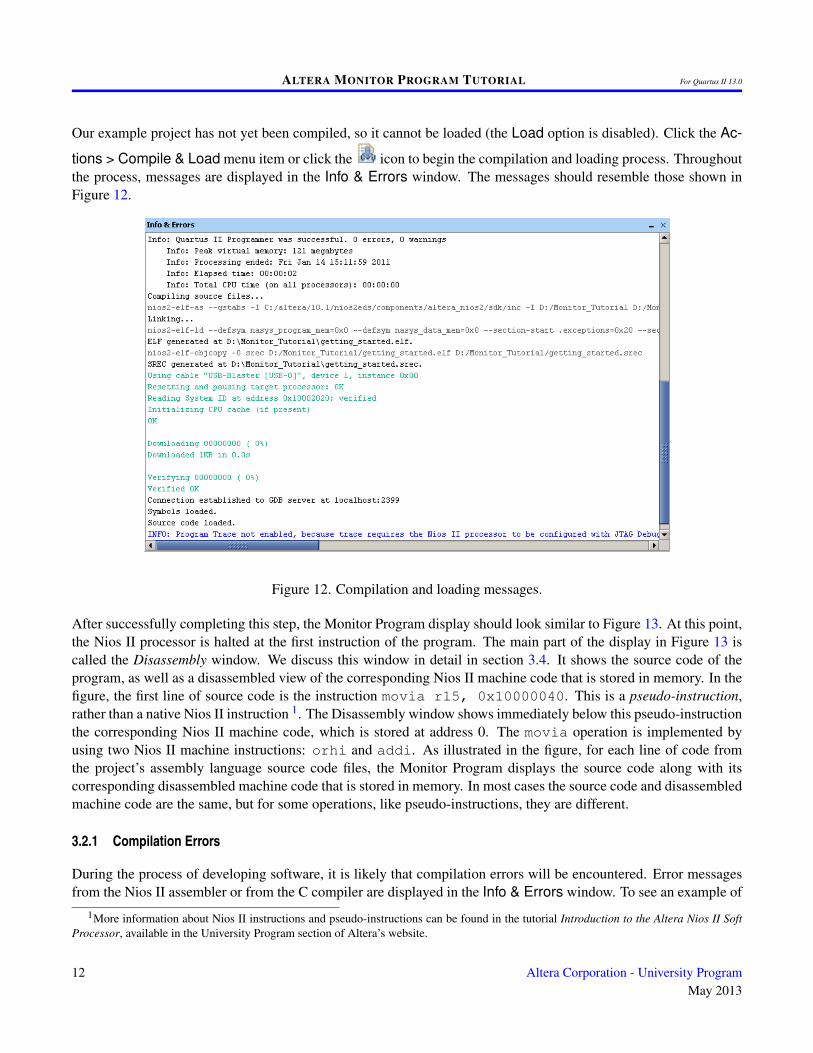
Our example project has not yet been compiled, so it cannot be loaded (the Load option is disabled). Click the Ac-
tions > Compile & Load menu item or click the icon to begin the compilation and loading process. Throughoutthe process, messages are displayed in the Info & Errors window. The messages should resemble those shown inFigure 12.
Figure 12. Compilation and loading messages.
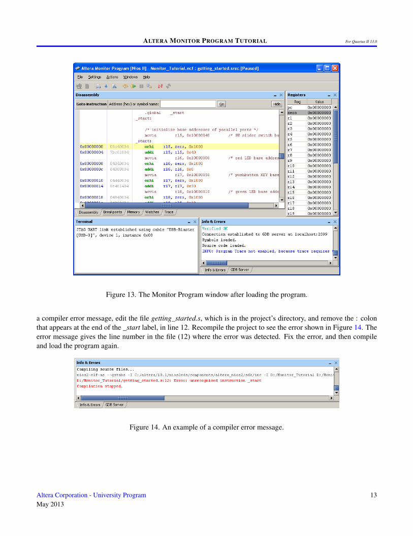
After successfully completing this step, the Monitor Program display should look similar to Figure 13. At this point,the Nios II processor is halted at the first instruction of the program. The main part of the display in Figure 13 iscalled the Disassembly window. We discuss this window in detail in section 3.4. It shows the source code of theprogram, as well as a disassembled view of the corresponding Nios II machine code that is stored in memory. In thefigure, the first line of source code is the instruction movia r15, 0x10000040. This is a pseudo-instruction,rather than a native Nios II instruction 1. The Disassembly window shows immediately below this pseudo-instructionthe corresponding Nios II machine code, which is stored at address 0. The movia operation is implemented byusing two Nios II machine instructions: orhi and addi. As illustrated in the figure, for each line of code fromthe project’s assembly language source code files, the Monitor Program displays the source code along with itscorresponding disassembled machine code that is stored in memory. In most cases the source code and disassembledmachine code are the same, but for some operations, like pseudo-instructions, they are different.
3.2.1 Compilation Errors
During the process of developing software, it is likely that compilation errors will be encountered. Error messagesfrom the Nios II assembler or from the C compiler are displayed in the Info & Errors window. To see an example of
1More information about Nios II instructions and pseudo-instructions can be found in the tutorial Introduction to the Altera Nios II SoftProcessor, available in the University Program section of Altera’s website.
12 Altera Corporation - University ProgramMay 2013
ALTERA MONITOR PROGRAM TUTORIAL For Quartus II 13.0
Figure 13. The Monitor Program window after loading the program.
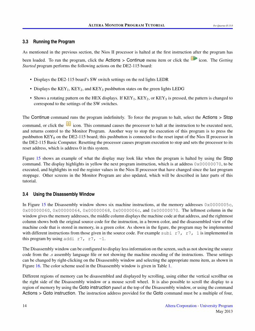
a compiler error message, edit the file getting_started.s, which is in the project’s directory, and remove the : colonthat appears at the end of the _start label, in line 12. Recompile the project to see the error shown in Figure 14. Theerror message gives the line number in the file (12) where the error was detected. Fix the error, and then compileand load the program again.
Figure 14. An example of a compiler error message.
Altera Corporation - University ProgramMay 2013
13
ALTERA MONITOR PROGRAM TUTORIAL For Quartus II 13.0
3.3 Running the Program
As mentioned in the previous section, the Nios II processor is halted at the first instruction after the program has
been loaded. To run the program, click the Actions > Continue menu item or click the icon. The GettingStarted program performs the following actions on the DE2-115 board:
• Displays the DE2-115 board’s SW switch settings on the red lights LEDR
• Displays the KEY1, KEY2, and KEY3 pushbutton states on the green lights LEDG
• Shows a rotating pattern on the HEX displays. If KEY1, KEY2, or KEY3 is pressed, the pattern is changed tocorrespond to the settings of the SW switches.
The Continue command runs the program indefinitely. To force the program to halt, select the Actions > Stop
command, or click the icon. This command causes the processor to halt at the instruction to be executed next,and returns control to the Monitor Program. Another way to stop the execution of this program is to press thepushbutton KEY0 on the DE2-115 board; this pushbutton is connected to the reset input of the Nios II processor inthe DE2-115 Basic Computer. Resetting the processor causes program execution to stop and sets the processor to itsreset address, which is address 0 in this system.
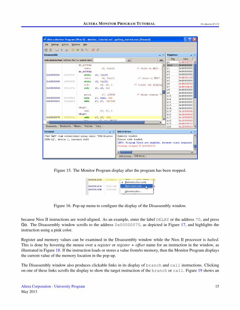
Figure 15 shows an example of what the display may look like when the program is halted by using the Stopcommand. The display highlights in yellow the next program instruction, which is at address 0x00000070, to beexecuted, and highlights in red the register values in the Nios II processor that have changed since the last programstoppage. Other screens in the Monitor Program are also updated, which will be described in later parts of thistutorial.
3.4 Using the Disassembly Window
In Figure 15 the Disassembly window shows six machine instructions, at the memory addresses 0x0000005c,0x00000060, 0x00000064, 0x00000068, 0x0000006c, and 0x00000070. The leftmost column in thewindow gives the memory addresses, the middle column displays the machine code at that address, and the rightmostcolumn shows both the original source code for the instruction, in a brown color, and the disassembled view of themachine code that is stored in memory, in a green color. As shown in the figure, the program may be implementedwith different instructions from those given in the source code. For example subi r7, r7, 1 is implemented inthis program by using addi r7, r7, -1.
The Disassembly window can be configured to display less information on the screen, such as not showing the sourcecode from the .s assembly language file or not showing the machine encoding of the instructions. These settingscan be changed by right-clicking on the Disassembly window and selecting the appropriate menu item, as shown inFigure 16. The color scheme used in the Disassembly window is given in Table 1.
Different regions of memory can be disassembled and displayed by scrolling, using either the vertical scrollbar onthe right side of the Disassembly window or a mouse scroll wheel. It is also possible to scroll the display to aregion of memory by using the Goto instruction panel at the top of the Disassembly window, or using the commandActions > Goto instruction. The instruction address provided for the Goto command must be a multiple of four,
14 Altera Corporation - University ProgramMay 2013
ALTERA MONITOR PROGRAM TUTORIAL For Quartus II 13.0
Figure 15. The Monitor Program display after the program has been stopped.
Figure 16. Pop-up menu to configure the display of the Disassembly window.
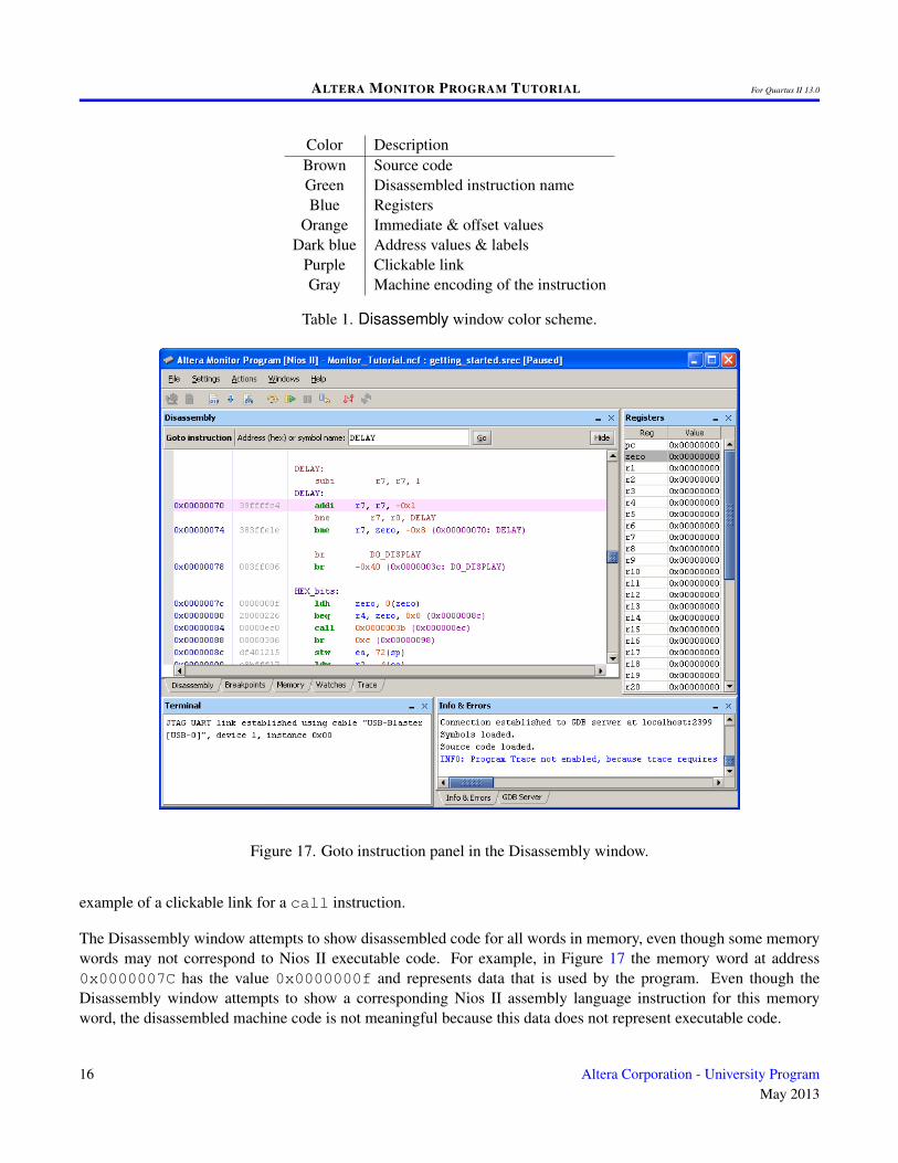
because Nios II instructions are word-aligned. As an example, enter the label DELAY or the address 70, and pressGo. The Disassembly window scrolls to the address 0x00000070, as depicted in Figure 17, and highlights theinstruction using a pink color.
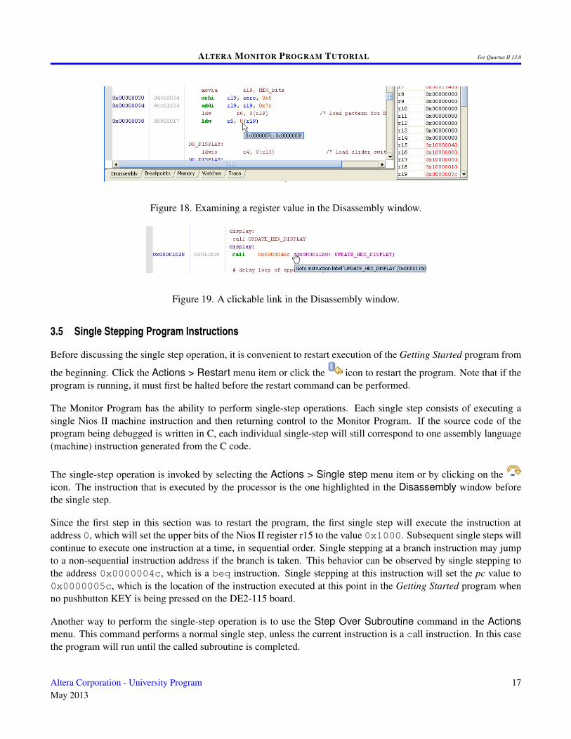
Register and memory values can be examined in the Disassembly window while the Nios II processor is halted.This is done by hovering the mouse over a register or register + offset name for an instruction in the window, asillustrated in Figure 18. If the instruction loads or stores a value from/to memory, then the Monitor Program displaysthe current value of the memory location in the pop-up.
The Disassembly window also produces clickable links in its display of branch and call instructions. Clickingon one of these links scrolls the display to show the target instruction of the branch or call. Figure 19 shows an
Altera Corporation - University ProgramMay 2013
15
ALTERA MONITOR PROGRAM TUTORIAL For Quartus II 13.0
Color DescriptionBrown Source codeGreen Disassembled instruction nameBlue Registers
Orange Immediate & offset valuesDark blue Address values & labels
Purple Clickable linkGray Machine encoding of the instruction
Table 1. Disassembly window color scheme.
Figure 17. Goto instruction panel in the Disassembly window.
example of a clickable link for a call instruction.
The Disassembly window attempts to show disassembled code for all words in memory, even though some memorywords may not correspond to Nios II executable code. For example, in Figure 17 the memory word at address0x0000007C has the value 0x0000000f and represents data that is used by the program. Even though theDisassembly window attempts to show a corresponding Nios II assembly language instruction for this memoryword, the disassembled machine code is not meaningful because this data does not represent executable code.
16 Altera Corporation - University ProgramMay 2013
ALTERA MONITOR PROGRAM TUTORIAL For Quartus II 13.0
Figure 18. Examining a register value in the Disassembly window.
Figure 19. A clickable link in the Disassembly window.
3.5 Single Stepping Program Instructions
Before discussing the single step operation, it is convenient to restart execution of the Getting Started program from
the beginning. Click the Actions > Restart menu item or click the icon to restart the program. Note that if theprogram is running, it must first be halted before the restart command can be performed.
The Monitor Program has the ability to perform single-step operations. Each single step consists of executing asingle Nios II machine instruction and then returning control to the Monitor Program. If the source code of theprogram being debugged is written in C, each individual single-step will still correspond to one assembly language(machine) instruction generated from the C code.
The single-step operation is invoked by selecting the Actions > Single step menu item or by clicking on theicon. The instruction that is executed by the processor is the one highlighted in the Disassembly window beforethe single step.
Since the first step in this section was to restart the program, the first single step will execute the instruction ataddress 0, which will set the upper bits of the Nios II register r15 to the value 0x1000. Subsequent single steps willcontinue to execute one instruction at a time, in sequential order. Single stepping at a branch instruction may jumpto a non-sequential instruction address if the branch is taken. This behavior can be observed by single stepping tothe address 0x0000004c, which is a beq instruction. Single stepping at this instruction will set the pc value to0x0000005c, which is the location of the instruction executed at this point in the Getting Started program whenno pushbutton KEY is being pressed on the DE2-115 board.
Another way to perform the single-step operation is to use the Step Over Subroutine command in the Actionsmenu. This command performs a normal single step, unless the current instruction is a call instruction. In this casethe program will run until the called subroutine is completed.
Altera Corporation - University ProgramMay 2013
17
ALTERA MONITOR PROGRAM TUTORIAL For Quartus II 13.0
3.6 Using Breakpoints
An instruction breakpoint provides a means of stopping a Nios II program when it reaches a specific address. Asimple procedure for setting an instruction breakpoint is:
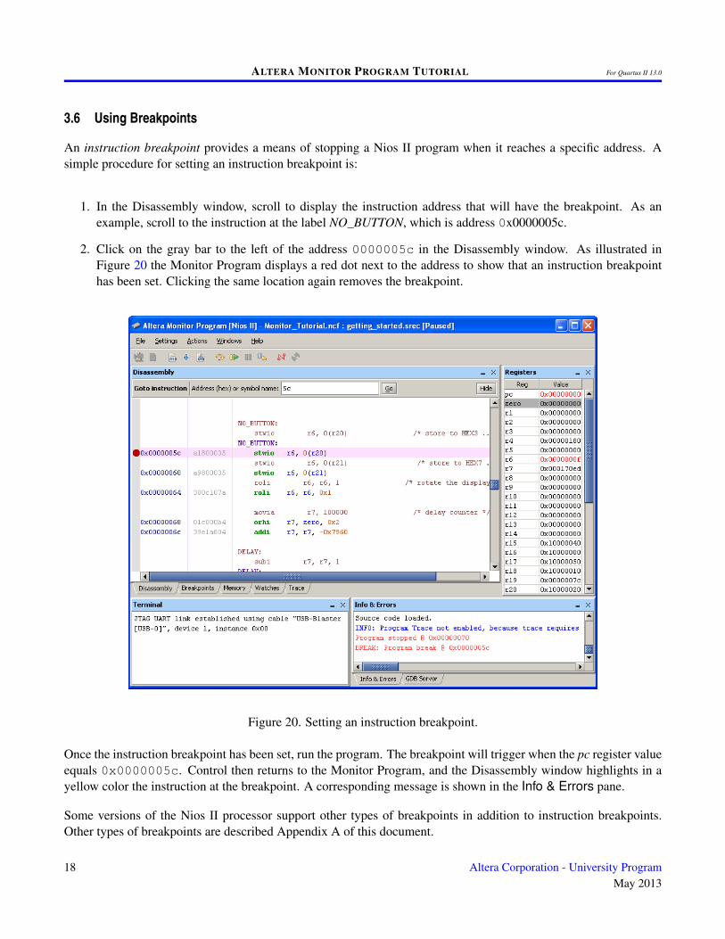
1. In the Disassembly window, scroll to display the instruction address that will have the breakpoint. As anexample, scroll to the instruction at the label NO_BUTTON, which is address 0x0000005c.
2. Click on the gray bar to the left of the address 0000005c in the Disassembly window. As illustrated inFigure 20 the Monitor Program displays a red dot next to the address to show that an instruction breakpointhas been set. Clicking the same location again removes the breakpoint.
Figure 20. Setting an instruction breakpoint.
Once the instruction breakpoint has been set, run the program. The breakpoint will trigger when the pc register valueequals 0x0000005c. Control then returns to the Monitor Program, and the Disassembly window highlights in ayellow color the instruction at the breakpoint. A corresponding message is shown in the Info & Errors pane.
Some versions of the Nios II processor support other types of breakpoints in addition to instruction breakpoints.Other types of breakpoints are described Appendix A of this document.
18 Altera Corporation - University ProgramMay 2013
ALTERA MONITOR PROGRAM TUTORIAL For Quartus II 13.0
3.7 Examining and Changing Register Values
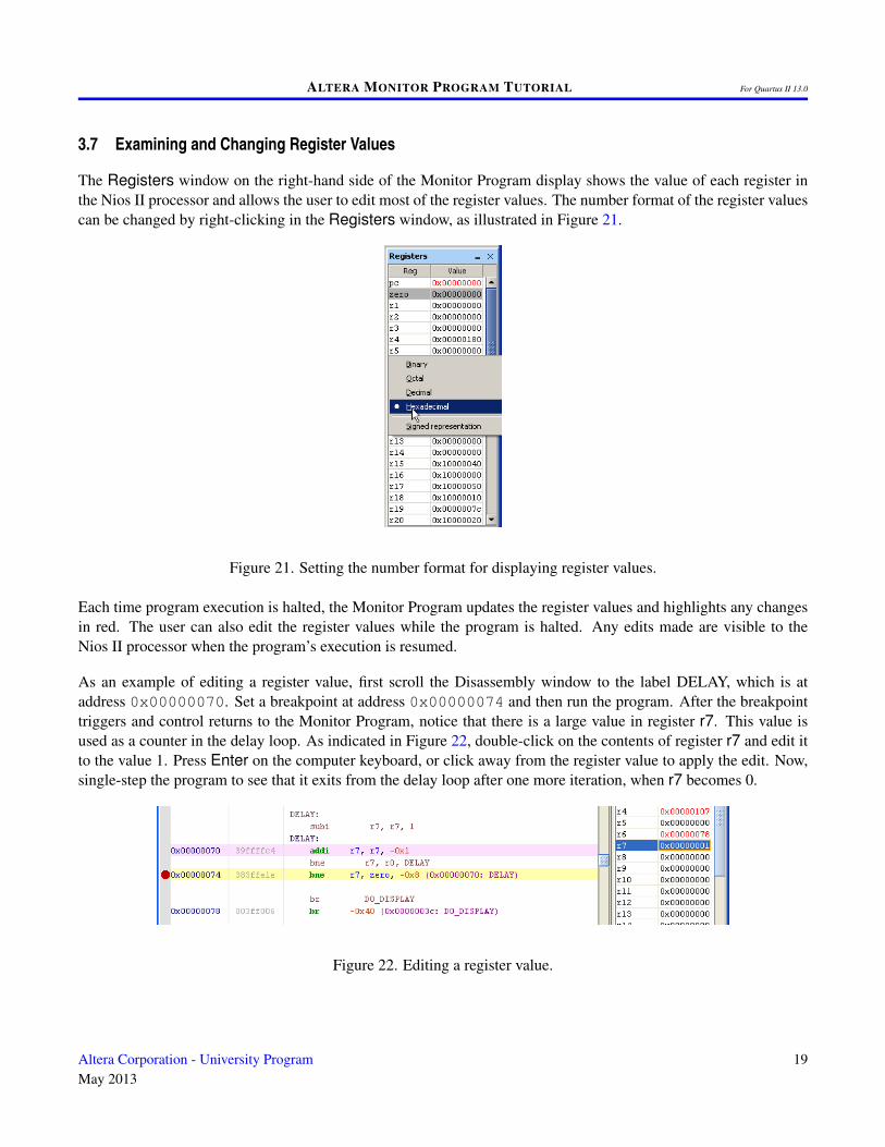
The Registers window on the right-hand side of the Monitor Program display shows the value of each register inthe Nios II processor and allows the user to edit most of the register values. The number format of the register valuescan be changed by right-clicking in the Registers window, as illustrated in Figure 21.
Figure 21. Setting the number format for displaying register values.
Each time program execution is halted, the Monitor Program updates the register values and highlights any changesin red. The user can also edit the register values while the program is halted. Any edits made are visible to theNios II processor when the program’s execution is resumed.
As an example of editing a register value, first scroll the Disassembly window to the label DELAY, which is ataddress 0x00000070. Set a breakpoint at address 0x00000074 and then run the program. After the breakpointtriggers and control returns to the Monitor Program, notice that there is a large value in register r7. This value isused as a counter in the delay loop. As indicated in Figure 22, double-click on the contents of register r7 and edit itto the value 1. Press Enter on the computer keyboard, or click away from the register value to apply the edit. Now,single-step the program to see that it exits from the delay loop after one more iteration, when r7 becomes 0.
Figure 22. Editing a register value.
Altera Corporation - University ProgramMay 2013
19
ALTERA MONITOR PROGRAM TUTORIAL For Quartus II 13.0
3.8 Examining and Changing Memory Contents
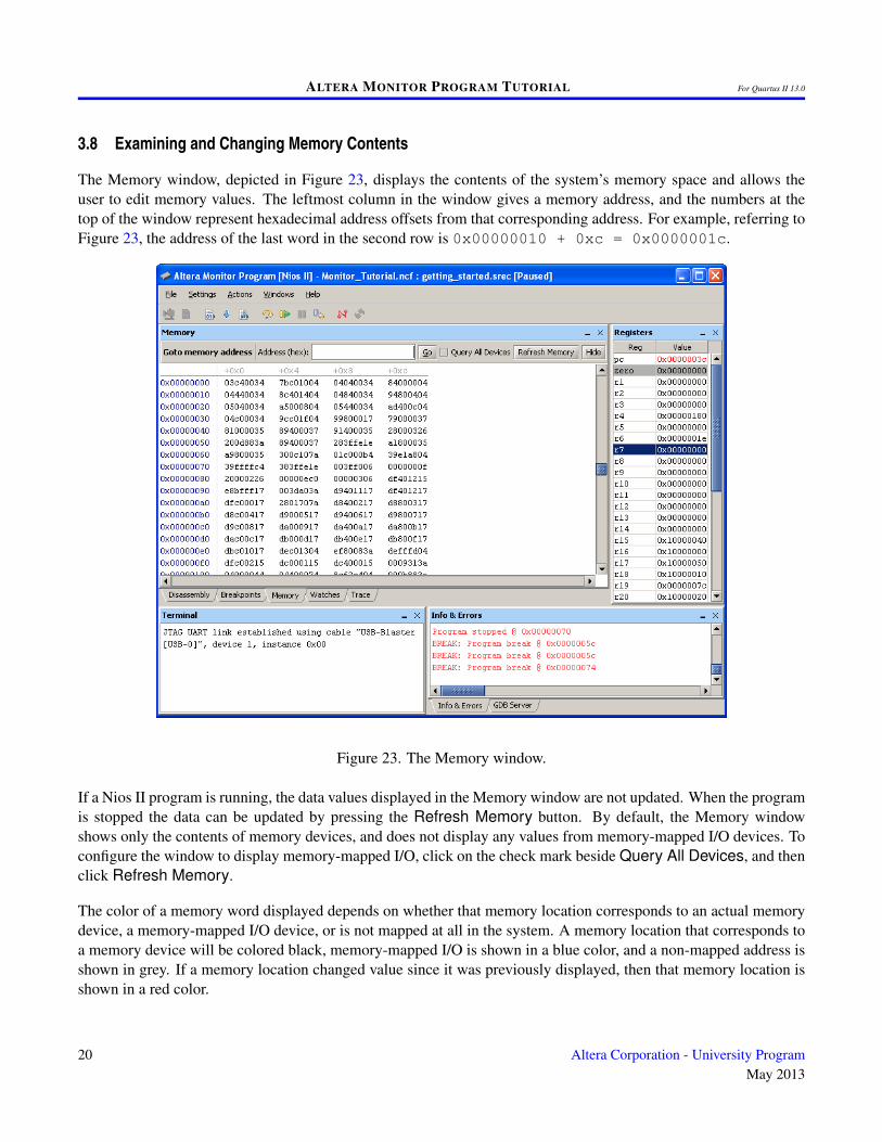
The Memory window, depicted in Figure 23, displays the contents of the system’s memory space and allows theuser to edit memory values. The leftmost column in the window gives a memory address, and the numbers at thetop of the window represent hexadecimal address offsets from that corresponding address. For example, referring toFigure 23, the address of the last word in the second row is 0x00000010 + 0xc = 0x0000001c.
Figure 23. The Memory window.
If a Nios II program is running, the data values displayed in the Memory window are not updated. When the programis stopped the data can be updated by pressing the Refresh Memory button. By default, the Memory windowshows only the contents of memory devices, and does not display any values from memory-mapped I/O devices. Toconfigure the window to display memory-mapped I/O, click on the check mark beside Query All Devices, and thenclick Refresh Memory.
The color of a memory word displayed depends on whether that memory location corresponds to an actual memorydevice, a memory-mapped I/O device, or is not mapped at all in the system. A memory location that corresponds toa memory device will be colored black, memory-mapped I/O is shown in a blue color, and a non-mapped address isshown in grey. If a memory location changed value since it was previously displayed, then that memory location isshown in a red color.
20 Altera Corporation - University ProgramMay 2013

ALTERA MONITOR PROGRAM TUTORIAL For Quartus II 13.0
Similar to the Disassembly window, it is possible to view different memory regions by scrolling using the verticalscroll bar on the right, or by using a mouse scroll wheel. There is also a Goto memory address panel, which isanalogous to the Goto instruction window discussed in section 3.4. Click to turn on the check mark beside QueryAll Devices in the memory window. In the Goto memory address panel type the address 0x10000000, and thenpress Go. The display scrolls to the requested address, which corresponds to memory-mapped I/O devices in theDE2-115 Basic Computer. Click the Refresh Memory button. The data displayed in blue at address 0x10000040corresponds to the settings of the 18 SW switches on the DE2-115 board. Experiment with different SW switchsettings and press Refresh Memory to see that the switch values are properly displayed.
As an example of editing a memory value, double-click on the memory word at address 0x10000000 and typethe hexadecimal data value 15555. Press Enter on the computer keyboard, or click away from the memory word toapply the edit. This memory-mapped address in the DE2-115 Basic Computer corresponds to the red lights LEDRon the DE2-115 board. Experiment by editing this memory location to different values and observe the LEDs.
It is possible to change the appearance of the Memory window in a number of ways, such as displaying data as bytes,half-words, or words, and so on. The Memory window provides additional features that are described in more detailin the Appendix A of this document.
4 Working with Project Files
Project files store the settings for a particular project, such as the specification of a hardware system and programsource files. A project file, which has the filename extension ncf, is stored into a project’s directory when the projectis created.
The Monitor Program provides the following commands, under the File menu, for working with project files:
1. New Project: Presents a series of screens that are used to create a new project.
2. Open Project: Displays a dialog to select an existing project file and loads the project.
3. Open Recent Project: This command displays the five most recently-used project files, and allows theseprojects to be reopened.
4. Save Project: Saves the current project’s settings. This command can be used to save a project’s settingsafter they have been modified by using the Settings command, which is described below.
4.1 Modifying the Settings of an Existing Project
After a project has been created, it is possible to modify many of its settings, if needed. This can be done by clicking
on the menu item Settings > System Settings in the Monitor Program, or the icon. This action will displaythe existing System Settings for the project, and allow them to be changed. Similarly, the program settings for the
project can be displayed or modified by using the command Settings > Program Settings, or the icon. Tochange these settings, the Monitor Program has to first be disconnected from the system being debugged. This can
be done by using the command Actions > Disconnect, or clicking the icon.
Altera Corporation - University ProgramMay 2013
21
ALTERA MONITOR PROGRAM TUTORIAL For Quartus II 13.0
5 Using the Monitor Program with a Nios II Evaluation License
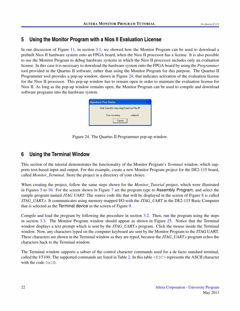
In our discussion of Figure 11, in section 3.1, we showed how the Monitor Program can be used to download aprebuilt Nios II hardware system onto an FPGA board, when the Nios II processor has a license. It is also possibleto use the Monitor Program to debug hardware systems in which the Nios II processor includes only an evaluationlicense. In this case it is necessary to download the hardware system onto the FPGA board by using the Programmertool provided in the Quartus II software, rather than using the Monitor Program for this purpose. The Quartus IIProgrammer tool provides a pop-up window, shown in Figure 24, that indicates activation of the evaluation licensefor the Nios II processor. This pop-up window has to remain open in order to maintain the evaluation license forNios II. As long as the pop-up window remains open, the Monitor Program can be used to compile and downloadsoftware programs into the hardware system.
Figure 24. The Quartus II Programmer pop-up window.
6 Using the Terminal Window
This section of the tutorial demonstrates the functionality of the Monitor Program’s Terminal window, which sup-ports text-based input and output. For this example, create a new Monitor Program project for the DE2-115 board,called Monitor_Terminal. Store the project in a directory of your choice.
When creating the project, follow the same steps shown for the Monitor_Tutorial project, which were illustratedin Figures 5 to 10. For the screen shown in Figure 7 set the program type to Assembly Program, and select thesample program named JTAG UART. The source code file that will be displayed in the screen of Figure 8 is calledJTAG_UART.s. It communicates using memory-mapped I/O with the JTAG_UART in the DE2-115 Basic Computerthat is selected as the Terminal device in the screen of Figure 9.
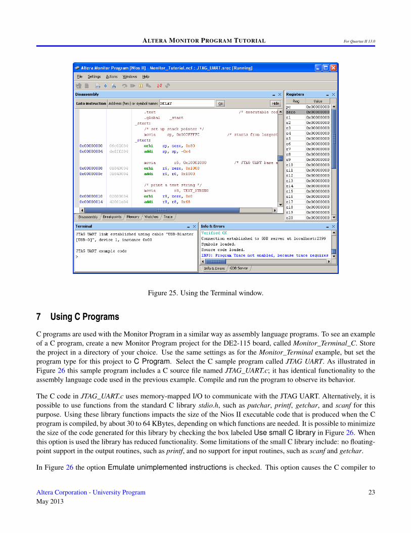
Compile and load the program by following the procedure in section 3.2. Then, run the program using the stepsin section 3.3. The Monitor Program window should appear as shown in Figure 25. Notice that the Terminalwindow displays a text prompt which is sent by the JTAG_UART.s program. Click the mouse inside the Terminalwindow. Now, any characters typed on the computer keyboard are sent by the Monitor Program to the JTAG UART.These characters are shown in the Terminal window as they are typed, because the JTAG_UART.s program echos thecharacters back to the Terminal window.
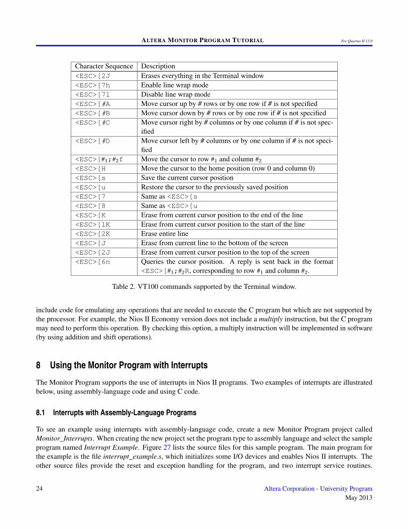
The Terminal window supports a subset of the control character commands used for a de facto standard terminal,called the VT100. The supported commands are listed in Table 2. In this table <ESC> represents the ASCII characterwith the code 0x1B.
22 Altera Corporation - University ProgramMay 2013
ALTERA MONITOR PROGRAM TUTORIAL For Quartus II 13.0
Figure 25. Using the Terminal window.
7 Using C Programs
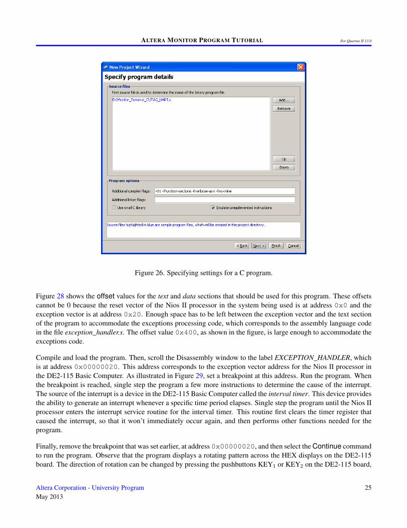
C programs are used with the Monitor Program in a similar way as assembly language programs. To see an exampleof a C program, create a new Monitor Program project for the DE2-115 board, called Monitor_Terminal_C. Storethe project in a directory of your choice. Use the same settings as for the Monitor_Terminal example, but set theprogram type for this project to C Program. Select the C sample program called JTAG UART. As illustrated inFigure 26 this sample program includes a C source file named JTAG_UART.c; it has identical functionality to theassembly language code used in the previous example. Compile and run the program to observe its behavior.
The C code in JTAG_UART.c uses memory-mapped I/O to communicate with the JTAG UART. Alternatively, it ispossible to use functions from the standard C library stdio.h, such as putchar, printf, getchar, and scanf for thispurpose. Using these library functions impacts the size of the Nios II executable code that is produced when the Cprogram is compiled, by about 30 to 64 KBytes, depending on which functions are needed. It is possible to minimizethe size of the code generated for this library by checking the box labeled Use small C library in Figure 26. Whenthis option is used the library has reduced functionality. Some limitations of the small C library include: no floating-point support in the output routines, such as printf, and no support for input routines, such as scanf and getchar.
In Figure 26 the option Emulate unimplemented instructions is checked. This option causes the C compiler to
Altera Corporation - University ProgramMay 2013
23
ALTERA MONITOR PROGRAM TUTORIAL For Quartus II 13.0
Character Sequence Description<ESC>[2J Erases everything in the Terminal window<ESC>[7h Enable line wrap mode<ESC>[7l Disable line wrap mode<ESC>[#A Move cursor up by # rows or by one row if # is not specified<ESC>[#B Move cursor down by # rows or by one row if # is not specified<ESC>[#C Move cursor right by # columns or by one column if # is not spec-
ified<ESC>[#D Move cursor left by # columns or by one column if # is not speci-
fied<ESC>[#1;#2f Move the cursor to row #1 and column #2
<ESC>[H Move the cursor to the home position (row 0 and column 0)<ESC>[s Save the current cursor position<ESC>[u Restore the cursor to the previously saved position<ESC>[7 Same as <ESC>[s<ESC>[8 Same as <ESC>[u<ESC>[K Erase from current cursor position to the end of the line<ESC>[1K Erase from current cursor position to the start of the line<ESC>[2K Erase entire line<ESC>[J Erase from current line to the bottom of the screen<ESC>[2J Erase from current cursor position to the top of the screen<ESC>[6n Queries the cursor position. A reply is sent back in the format
<ESC>[#1;#2R, corresponding to row #1 and column #2.
Table 2. VT100 commands supported by the Terminal window.
include code for emulating any operations that are needed to execute the C program but which are not supported bythe processor. For example, the Nios II Economy version does not include a multiply instruction, but the C programmay need to perform this operation. By checking this option, a multiply instruction will be implemented in software(by using addition and shift operations).
8 Using the Monitor Program with Interrupts
The Monitor Program supports the use of interrupts in Nios II programs. Two examples of interrupts are illustratedbelow, using assembly-language code and using C code.
8.1 Interrupts with Assembly-Language Programs
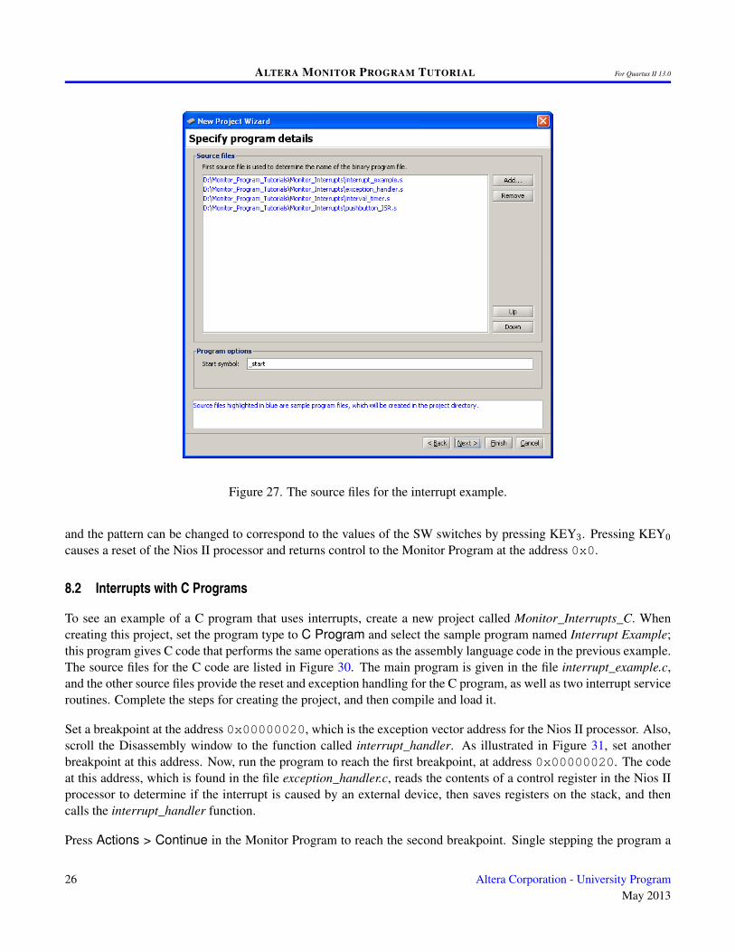
To see an example using interrupts with assembly-language code, create a new Monitor Program project calledMonitor_Interrupts. When creating the new project set the program type to assembly language and select the sampleprogram named Interrupt Example. Figure 27 lists the source files for this sample program. The main program forthe example is the file interrupt_example.s, which initializes some I/O devices and enables Nios II interrupts. Theother source files provide the reset and exception handling for the program, and two interrupt service routines.
24 Altera Corporation - University ProgramMay 2013
ALTERA MONITOR PROGRAM TUTORIAL For Quartus II 13.0
Figure 26. Specifying settings for a C program.
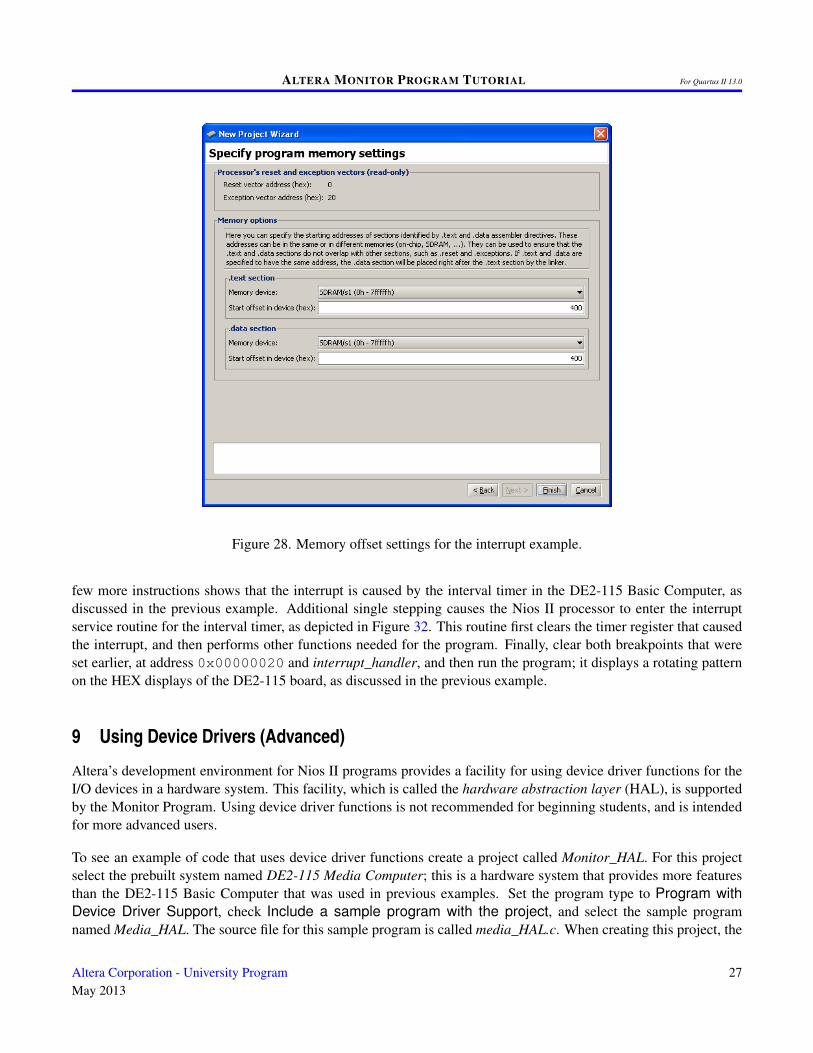
Figure 28 shows the offset values for the text and data sections that should be used for this program. These offsetscannot be 0 because the reset vector of the Nios II processor in the system being used is at address 0x0 and theexception vector is at address 0x20. Enough space has to be left between the exception vector and the text sectionof the program to accommodate the exceptions processing code, which corresponds to the assembly language codein the file exception_handler.s. The offset value 0x400, as shown in the figure, is large enough to accommodate theexceptions code.
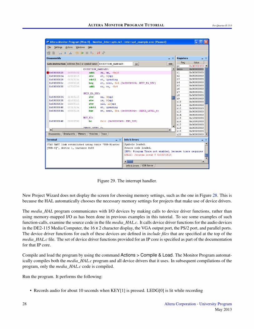
Compile and load the program. Then, scroll the Disassembly window to the label EXCEPTION_HANDLER, whichis at address 0x00000020. This address corresponds to the exception vector address for the Nios II processor inthe DE2-115 Basic Computer. As illustrated in Figure 29, set a breakpoint at this address. Run the program. Whenthe breakpoint is reached, single step the program a few more instructions to determine the cause of the interrupt.The source of the interrupt is a device in the DE2-115 Basic Computer called the interval timer. This device providesthe ability to generate an interrupt whenever a specific time period elapses. Single step the program until the Nios IIprocessor enters the interrupt service routine for the interval timer. This routine first clears the timer register thatcaused the interrupt, so that it won’t immediately occur again, and then performs other functions needed for theprogram.
Finally, remove the breakpoint that was set earlier, at address 0x00000020, and then select the Continue commandto run the program. Observe that the program displays a rotating pattern across the HEX displays on the DE2-115board. The direction of rotation can be changed by pressing the pushbuttons KEY1 or KEY2 on the DE2-115 board,
Altera Corporation - University ProgramMay 2013
25
ALTERA MONITOR PROGRAM TUTORIAL For Quartus II 13.0
Figure 27. The source files for the interrupt example.
and the pattern can be changed to correspond to the values of the SW switches by pressing KEY3. Pressing KEY0
causes a reset of the Nios II processor and returns control to the Monitor Program at the address 0x0.
8.2 Interrupts with C Programs
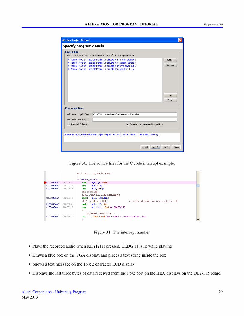
To see an example of a C program that uses interrupts, create a new project called Monitor_Interrupts_C. Whencreating this project, set the program type to C Program and select the sample program named Interrupt Example;this program gives C code that performs the same operations as the assembly language code in the previous example.The source files for the C code are listed in Figure 30. The main program is given in the file interrupt_example.c,and the other source files provide the reset and exception handling for the C program, as well as two interrupt serviceroutines. Complete the steps for creating the project, and then compile and load it.
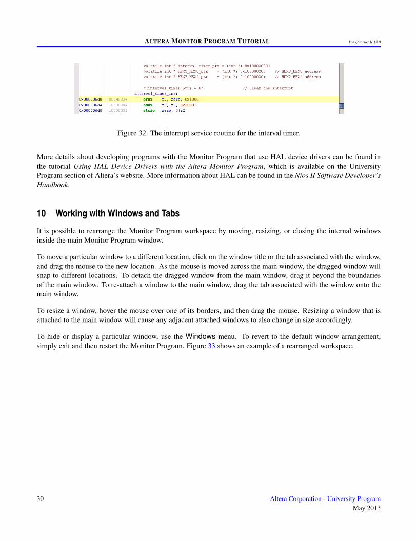
Set a breakpoint at the address 0x00000020, which is the exception vector address for the Nios II processor. Also,scroll the Disassembly window to the function called interrupt_handler. As illustrated in Figure 31, set anotherbreakpoint at this address. Now, run the program to reach the first breakpoint, at address 0x00000020. The codeat this address, which is found in the file exception_handler.c, reads the contents of a control register in the Nios IIprocessor to determine if the interrupt is caused by an external device, then saves registers on the stack, and thencalls the interrupt_handler function.
Press Actions > Continue in the Monitor Program to reach the second breakpoint. Single stepping the program a
26 Altera Corporation - University ProgramMay 2013
ALTERA MONITOR PROGRAM TUTORIAL For Quartus II 13.0
Figure 28. Memory offset settings for the interrupt example.
few more instructions shows that the interrupt is caused by the interval timer in the DE2-115 Basic Computer, asdiscussed in the previous example. Additional single stepping causes the Nios II processor to enter the interruptservice routine for the interval timer, as depicted in Figure 32. This routine first clears the timer register that causedthe interrupt, and then performs other functions needed for the program. Finally, clear both breakpoints that wereset earlier, at address 0x00000020 and interrupt_handler, and then run the program; it displays a rotating patternon the HEX displays of the DE2-115 board, as discussed in the previous example.
9 Using Device Drivers (Advanced)
Altera’s development environment for Nios II programs provides a facility for using device driver functions for theI/O devices in a hardware system. This facility, which is called the hardware abstraction layer (HAL), is supportedby the Monitor Program. Using device driver functions is not recommended for beginning students, and is intendedfor more advanced users.
To see an example of code that uses device driver functions create a project called Monitor_HAL. For this projectselect the prebuilt system named DE2-115 Media Computer; this is a hardware system that provides more featuresthan the DE2-115 Basic Computer that was used in previous examples. Set the program type to Program withDevice Driver Support, check Include a sample program with the project, and select the sample programnamed Media_HAL. The source file for this sample program is called media_HAL.c. When creating this project, the
Altera Corporation - University ProgramMay 2013
27
ALTERA MONITOR PROGRAM TUTORIAL For Quartus II 13.0
Figure 29. The interrupt handler.
New Project Wizard does not display the screen for choosing memory settings, such as the one in Figure 28. This isbecause the HAL automatically chooses the necessary memory settings for projects that make use of device drivers.
The media_HAL program communicates with I/O devices by making calls to device driver functions, rather thanusing memory-mapped I/O as has been done in previous examples in this tutorial. To see some examples of suchfunction-calls, examine the source code in the file media_HAL.c. It calls device driver functions for the audio devicesin the DE2-115 Media Computer, the 16 x 2 character display, the VGA output port, the PS/2 port, and parallel ports.The device driver functions for each of these devices are defined in include files that are specified at the top of themedia_HAL.c file. The set of device driver functions provided for an IP core is specified as part of the documentationfor that IP core.
Compile and load the program by using the command Actions > Compile & Load. The Monitor Program automat-ically compiles both the media_HAL.c program and all device drivers that it uses. In subsequent compilations of theprogram, only the media_HAL.c code is compiled.
Run the program. It performs the following:
• Records audio for about 10 seconds when KEY[1] is pressed. LEDG[0] is lit while recording
28 Altera Corporation - University ProgramMay 2013
ALTERA MONITOR PROGRAM TUTORIAL For Quartus II 13.0
Figure 30. The source files for the C code interrupt example.
Figure 31. The interrupt handler.
• Plays the recorded audio when KEY[2] is pressed. LEDG[1] is lit while playing
• Draws a blue box on the VGA display, and places a text string inside the box
• Shows a text message on the 16 x 2 character LCD display
• Displays the last three bytes of data received from the PS/2 port on the HEX displays on the DE2-115 board
Altera Corporation - University ProgramMay 2013
29
ALTERA MONITOR PROGRAM TUTORIAL For Quartus II 13.0
Figure 32. The interrupt service routine for the interval timer.
More details about developing programs with the Monitor Program that use HAL device drivers can be found inthe tutorial Using HAL Device Drivers with the Altera Monitor Program, which is available on the UniversityProgram section of Altera’s website. More information about HAL can be found in the Nios II Software Developer’sHandbook.
10 Working with Windows and Tabs
It is possible to rearrange the Monitor Program workspace by moving, resizing, or closing the internal windowsinside the main Monitor Program window.
To move a particular window to a different location, click on the window title or the tab associated with the window,and drag the mouse to the new location. As the mouse is moved across the main window, the dragged window willsnap to different locations. To detach the dragged window from the main window, drag it beyond the boundariesof the main window. To re-attach a window to the main window, drag the tab associated with the window onto themain window.
To resize a window, hover the mouse over one of its borders, and then drag the mouse. Resizing a window that isattached to the main window will cause any adjacent attached windows to also change in size accordingly.
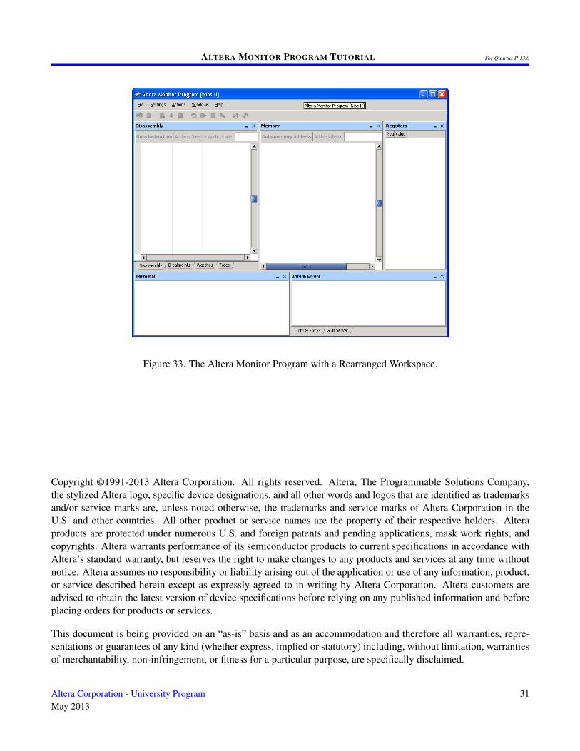
To hide or display a particular window, use the Windows menu. To revert to the default window arrangement,simply exit and then restart the Monitor Program. Figure 33 shows an example of a rearranged workspace.
30 Altera Corporation - University ProgramMay 2013
ALTERA MONITOR PROGRAM TUTORIAL For Quartus II 13.0
Figure 33. The Altera Monitor Program with a Rearranged Workspace.
Copyright ©1991-2013 Altera Corporation. All rights reserved. Altera, The Programmable Solutions Company,the stylized Altera logo, specific device designations, and all other words and logos that are identified as trademarksand/or service marks are, unless noted otherwise, the trademarks and service marks of Altera Corporation in theU.S. and other countries. All other product or service names are the property of their respective holders. Alteraproducts are protected under numerous U.S. and foreign patents and pending applications, mask work rights, andcopyrights. Altera warrants performance of its semiconductor products to current specifications in accordance withAltera’s standard warranty, but reserves the right to make changes to any products and services at any time withoutnotice. Altera assumes no responsibility or liability arising out of the application or use of any information, product,or service described herein except as expressly agreed to in writing by Altera Corporation. Altera customers areadvised to obtain the latest version of device specifications before relying on any published information and beforeplacing orders for products or services.
This document is being provided on an “as-is” basis and as an accommodation and therefore all warranties, repre-sentations or guarantees of any kind (whether express, implied or statutory) including, without limitation, warrantiesof merchantability, non-infringement, or fitness for a particular purpose, are specifically disclaimed.
Altera Corporation - University ProgramMay 2013
31
ALTERA MONITOR PROGRAM TUTORIAL For Quartus II 13.0
11 Appendix A
This appendix describes a number of Monitor Program features that are useful for advanced debugging or otherpurposes.
11.1 Using the Breakpoints Window
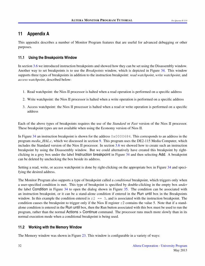
In section 3.6 we introduced instruction breakpoints and showed how they can be set using the Disassembly window.Another way to set breakpoints is to use the Breakpoints window, which is depicted in Figure 34. This windowsupports three types of breakpoints in addition to the instruction breakpoint: read watchpoint, write watchpoint, andaccess watchpoint, described below:
1. Read watchpoint: the Nios II processor is halted when a read operation is performed on a specific address
2. Write watchpoint: the Nios II processor is halted when a write operation is performed on a specific address
3. Access watchpoint: the Nios II processor is halted when a read or write operation is performed on a specificaddress
Each of the above types of breakpoints requires the use of the Standard or Fast version of the Nios II processor.These breakpoint types are not available when using the Economy version of Nios II.
In Figure 34 an instruction breakpoint is shown for the address 0x0000684. This corresponds to an address in theprogram media_HAL.c, which we discussed in section 9. This program uses the DE2-115 Media Computer, whichincludes the Standard version of the Nios II processor. In section 3.6 we showed how to create such an instructionbreakpoint by using the Disassembly window. But we could alternatively have created this breakpoint by right-clicking in a grey box under the label Instruction breakpoint in Figure 34 and then selecting Add. A breakpointcan be deleted by unchecking the box beside its address.
Setting a read, write, or access watchpoint is done by right-clicking on the appropriate box in Figure 34 and speci-fying the desired address.
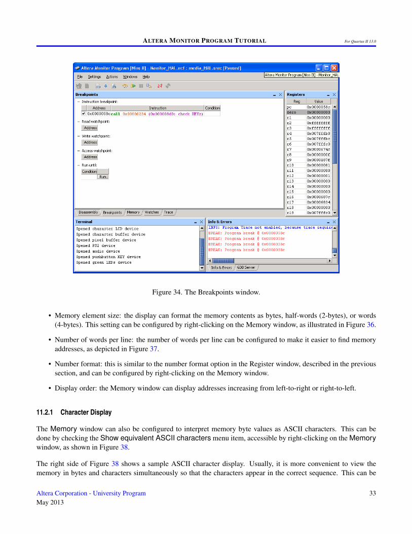
The Monitor Program also supports a type of breakpoint called a conditional breakpoint, which triggers only whena user-specified condition is met. This type of breakpoint is specified by double-clicking in the empty box underthe label Condition in Figure 34 to open the dialog shown in Figure 35. The condition can be associated withan instruction breakpoint, or it can be a stand-alone condition if entered in the Run until box in the Breakpointswindow. In this example the condition entered is r2 == 5, and is associated with the instruction breakpoint. Thecondition causes the breakpoint to trigger only if the Nios II register r2 contains the value 5. Note that if a stand-alone condition is entered in the Run until box, then the Run button associated with this box must be used to run theprogram, rather than the normal Actions > Continue command. The processor runs much more slowly than in itsnormal execution mode when a conditional breakpoint is being used.
11.2 Working with the Memory Window
The Memory window was shown in Figure 23. This window is configurable in a variety of ways:
32 Altera Corporation - University ProgramMay 2013
ALTERA MONITOR PROGRAM TUTORIAL For Quartus II 13.0
Figure 34. The Breakpoints window.
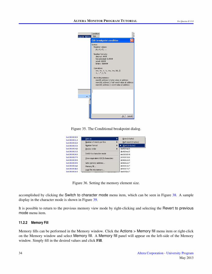
• Memory element size: the display can format the memory contents as bytes, half-words (2-bytes), or words(4-bytes). This setting can be configured by right-clicking on the Memory window, as illustrated in Figure 36.
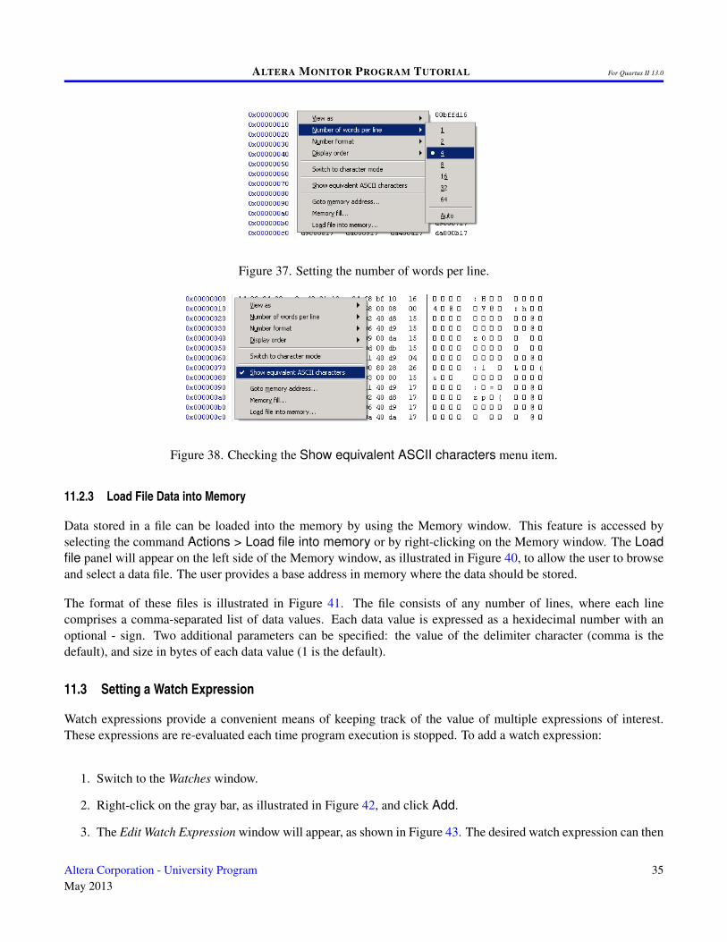
• Number of words per line: the number of words per line can be configured to make it easier to find memoryaddresses, as depicted in Figure 37.
• Number format: this is similar to the number format option in the Register window, described in the previoussection, and can be configured by right-clicking on the Memory window.
• Display order: the Memory window can display addresses increasing from left-to-right or right-to-left.
11.2.1 Character Display
The Memory window can also be configured to interpret memory byte values as ASCII characters. This can bedone by checking the Show equivalent ASCII characters menu item, accessible by right-clicking on the Memorywindow, as shown in Figure 38.
The right side of Figure 38 shows a sample ASCII character display. Usually, it is more convenient to view thememory in bytes and characters simultaneously so that the characters appear in the correct sequence. This can be
Altera Corporation - University ProgramMay 2013
33
ALTERA MONITOR PROGRAM TUTORIAL For Quartus II 13.0
Figure 35. The Conditional breakpoint dialog.
Figure 36. Setting the memory element size.
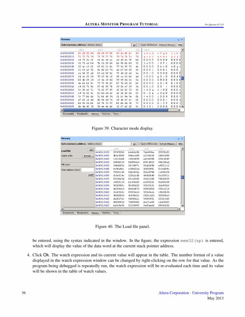
accomplished by clicking the Switch to character mode menu item, which can be seen in Figure 38. A sampledisplay in the character mode is shown in Figure 39.
It is possible to return to the previous memory view mode by right-clicking and selecting the Revert to previousmode menu item.
11.2.2 Memory Fill
Memory fills can be performed in the Memory window. Click the Actions > Memory fill menu item or right-clickon the Memory window and select Memory fill. A Memory fill panel will appear on the left-side of the Memorywindow. Simply fill in the desired values and click Fill.
34 Altera Corporation - University ProgramMay 2013
ALTERA MONITOR PROGRAM TUTORIAL For Quartus II 13.0
Figure 37. Setting the number of words per line.
Figure 38. Checking the Show equivalent ASCII characters menu item.
11.2.3 Load File Data into Memory
Data stored in a file can be loaded into the memory by using the Memory window. This feature is accessed byselecting the command Actions > Load file into memory or by right-clicking on the Memory window. The Loadfile panel will appear on the left side of the Memory window, as illustrated in Figure 40, to allow the user to browseand select a data file. The user provides a base address in memory where the data should be stored.
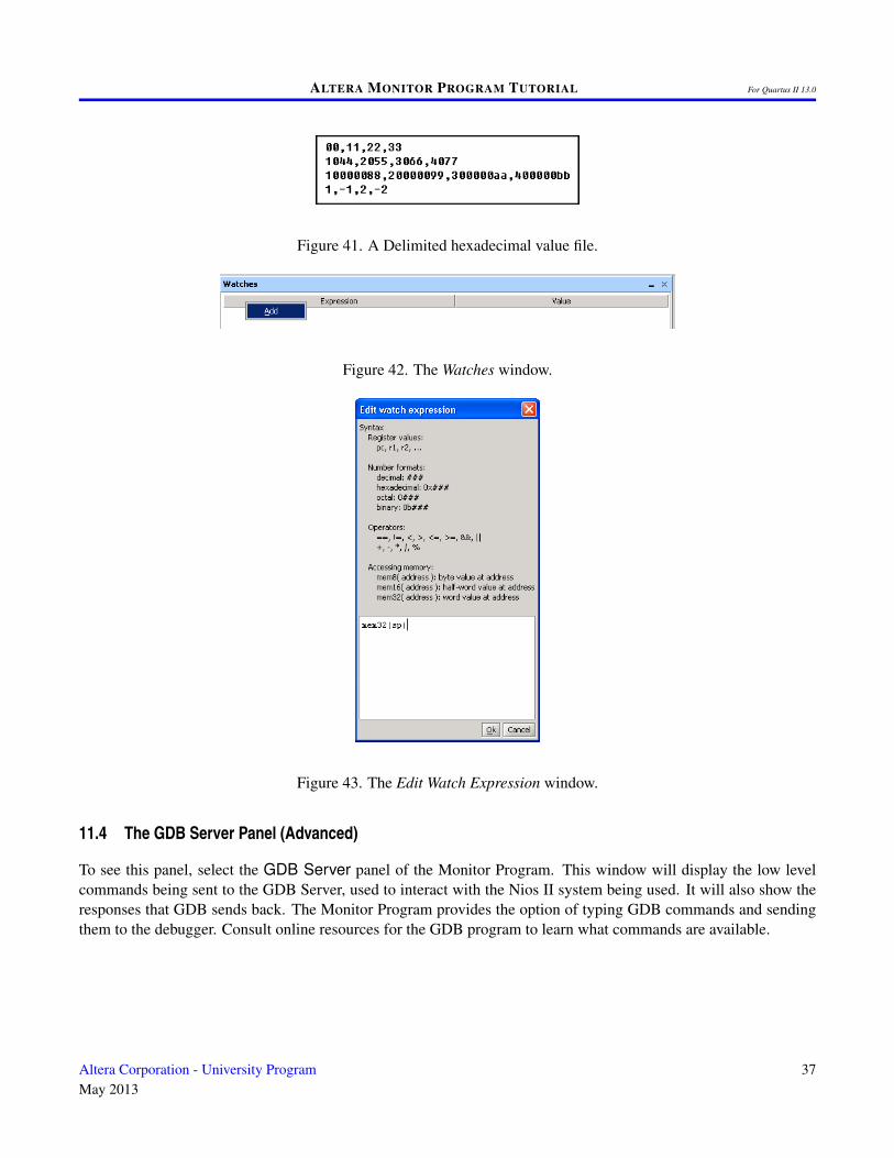
The format of these files is illustrated in Figure 41. The file consists of any number of lines, where each linecomprises a comma-separated list of data values. Each data value is expressed as a hexidecimal number with anoptional - sign. Two additional parameters can be specified: the value of the delimiter character (comma is thedefault), and size in bytes of each data value (1 is the default).
11.3 Setting a Watch Expression
Watch expressions provide a convenient means of keeping track of the value of multiple expressions of interest.These expressions are re-evaluated each time program execution is stopped. To add a watch expression:
1. Switch to the Watches window.
2. Right-click on the gray bar, as illustrated in Figure 42, and click Add.
3. The Edit Watch Expression window will appear, as shown in Figure 43. The desired watch expression can then
Altera Corporation - University ProgramMay 2013
35
ALTERA MONITOR PROGRAM TUTORIAL For Quartus II 13.0
Figure 39. Character mode display.
Figure 40. The Load file panel.
be entered, using the syntax indicated in the window. In the figure, the expression mem32(sp) is entered,which will display the value of the data word at the current stack pointer address.
4. Click Ok. The watch expression and its current value will appear in the table. The number format of a valuedisplayed in the watch expression window can be changed by right-clicking on the row for that value. As theprogram being debugged is repeatedly run, the watch expression will be re-evaluated each time and its valuewill be shown in the table of watch values.
36 Altera Corporation - University ProgramMay 2013
ALTERA MONITOR PROGRAM TUTORIAL For Quartus II 13.0
Figure 41. A Delimited hexadecimal value file.
Figure 42. The Watches window.
Figure 43. The Edit Watch Expression window.
11.4 The GDB Server Panel (Advanced)
To see this panel, select the GDB Server panel of the Monitor Program. This window will display the low levelcommands being sent to the GDB Server, used to interact with the Nios II system being used. It will also show theresponses that GDB sends back. The Monitor Program provides the option of typing GDB commands and sendingthem to the debugger. Consult online resources for the GDB program to learn what commands are available.
Altera Corporation - University ProgramMay 2013
37

ALTERA MONITOR PROGRAM TUTORIAL For Quartus II 13.0
11.5 Running Multiple Instances of the Monitor Program (Advanced)
In some cases, it may be useful to run more than one instance of the Monitor Program on the same computer. Forexample, the selected system may contain more than one Nios II processor. An instance of the Monitor Program isrequired to run and debug programs on each available processor. As described in Section 3.1, it is possible to selecta particular processor in a system via the Processor drop-down list in the New Project Wizard and Project Settingswindows.
The Monitor Program uses GDB Server to interact with the Nios II hardware system, and connects to the GDBServer using TCP ports. By default, the Monitor Program uses port 2399 as the base port, and to connect to eachprocessor in a system, the Monitor Program will attempt to use a port located at a fixed offset from this base port.For example, a single system consisting of 4 processors corresponds to ports 2399-2402.
However, the Monitor Program does not detect any ports that may already be in use by other applications. If the Mon-itor Program fails to connect to the GDB Server due to a port conflict, then the base port number can be changed bycreating an environment variable called ALTERA_MONITOR_DEBUGGER_BASE_PORT and specifying a differentnumber.
It is also possible to have more than one board connected to the host computer. As described in Section 3.1, aparticular board can be selected via the Host connection drop-down list in the New Project Wizard and ProjectSettings windows. In this case, a separate instance of the Monitor Program is needed to interact with each processoron each physical board. By default, the Monitor Program assumes a maximum of 10 Nios II processors per board.This means that ports 2399-2408 are used by the Monitor Program for the first board connected to the computer, andthe first processor on the second board will use port 2409.
It is possible to specify a different value for the maximum number of processors per Nios II hardware system bycreating an environment variable called ALTERA_MONITOR_DEBUGGER_MAX_PORTS_PER_CABLE and speci-fying a different number. This is useful if a system contains more than 10 Nios II processors. It is also useful if aport conflict exists and none of the systems contain 10 or more processors. In this case, decreasing this number (inconjunction with changing the base port number) may provide a solution.
38 Altera Corporation - University ProgramMay 2013
ALTERA MONITOR PROGRAM TUTORIAL For Quartus II 13.0
11.6 Examining the Instruction Trace (Advanced)
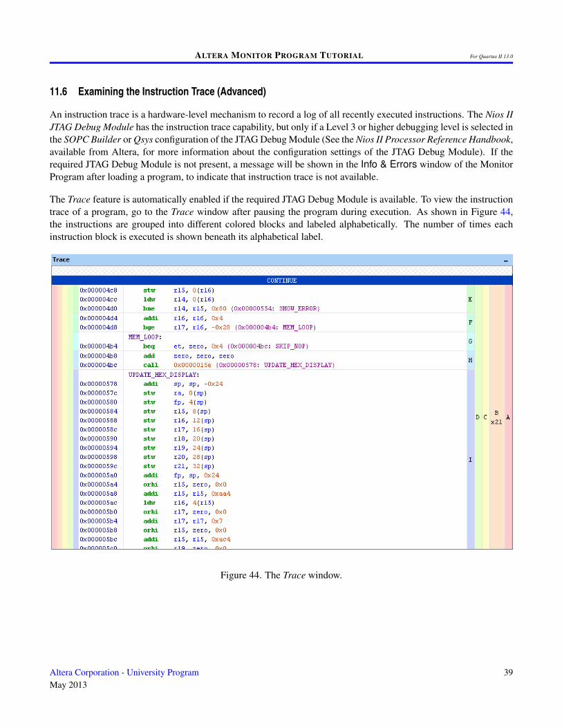
An instruction trace is a hardware-level mechanism to record a log of all recently executed instructions. The Nios IIJTAG Debug Module has the instruction trace capability, but only if a Level 3 or higher debugging level is selected inthe SOPC Builder or Qsys configuration of the JTAG Debug Module (See the Nios II Processor Reference Handbook,available from Altera, for more information about the configuration settings of the JTAG Debug Module). If therequired JTAG Debug Module is not present, a message will be shown in the Info & Errors window of the MonitorProgram after loading a program, to indicate that instruction trace is not available.
The Trace feature is automatically enabled if the required JTAG Debug Module is available. To view the instructiontrace of a program, go to the Trace window after pausing the program during execution. As shown in Figure 44,the instructions are grouped into different colored blocks and labeled alphabetically. The number of times eachinstruction block is executed is shown beneath its alphabetical label.
Figure 44. The Trace window.
Altera Corporation - University ProgramMay 2013
39
ALTERA MONITOR PROGRAM TUTORIAL For Quartus II 13.0
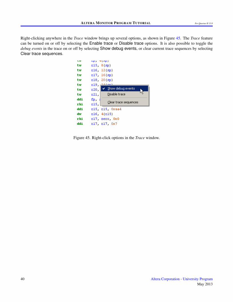
Right-clicking anywhere in the Trace window brings up several options, as shown in Figure 45. The Trace featurecan be turned on or off by selecting the Enable trace or Disable trace options. It is also possible to toggle thedebug events in the trace on or off by selecting Show debug events, or clear current trace sequences by selectingClear trace sequences.
Figure 45. Right-click options in the Trace window.
40 Altera Corporation - University ProgramMay 2013
ALTERA MONITOR PROGRAM TUTORIAL For Quartus II 13.0
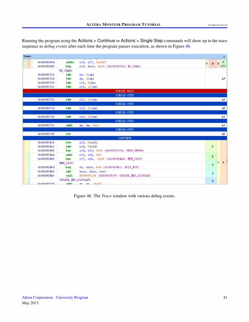
Running the program using the Actions > Continue or Actions > Single Step commands will show up in the tracesequence as debug events after each time the program pauses execution, as shown in Figure 46.
Figure 46. The Trace window with various debug events.
Altera Corporation - University ProgramMay 2013
41
ALTERA MONITOR PROGRAM TUTORIAL For Quartus II 13.0
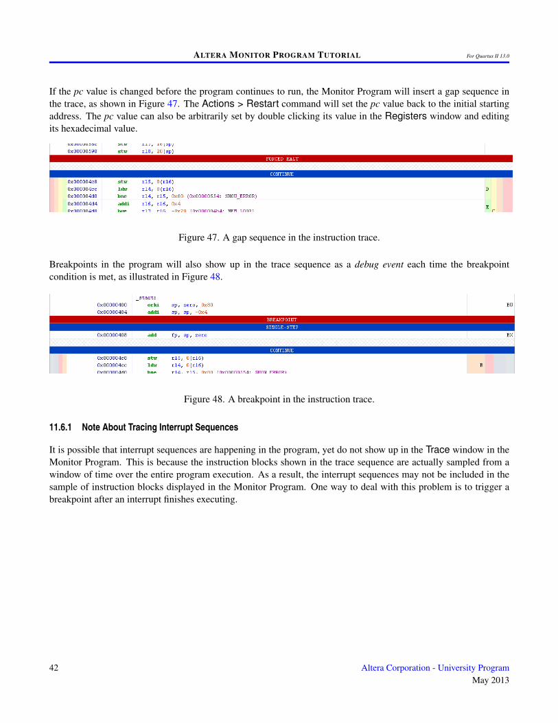
If the pc value is changed before the program continues to run, the Monitor Program will insert a gap sequence inthe trace, as shown in Figure 47. The Actions > Restart command will set the pc value back to the initial startingaddress. The pc value can also be arbitrarily set by double clicking its value in the Registers window and editingits hexadecimal value.
Figure 47. A gap sequence in the instruction trace.
Breakpoints in the program will also show up in the trace sequence as a debug event each time the breakpointcondition is met, as illustrated in Figure 48.
Figure 48. A breakpoint in the instruction trace.
11.6.1 Note About Tracing Interrupt Sequences
It is possible that interrupt sequences are happening in the program, yet do not show up in the Trace window in theMonitor Program. This is because the instruction blocks shown in the trace sequence are actually sampled from awindow of time over the entire program execution. As a result, the interrupt sequences may not be included in thesample of instruction blocks displayed in the Monitor Program. One way to deal with this problem is to trigger abreakpoint after an interrupt finishes executing.
42 Altera Corporation - University ProgramMay 2013

ALTERA MONITOR PROGRAM TUTORIAL For Quartus II 13.0
Copyright ©1991-2013 Altera Corporation. All rights reserved. Altera, The Programmable Solutions Company, thestylized Altera logo, specific device designations, and all other words and logos that are identified as trademarksand/or service marks are, unless noted otherwise, the trademarks and service marks of Altera Corporation in theU.S. and other countries. All other product or service names are the property of their respective holders. Alteraproducts are protected under numerous U.S. and foreign patents and pending applications, mask work rights, andcopyrights. Altera warrants performance of its semiconductor products to current specifications in accordance withAltera’s standard warranty, but reserves the right to make changes to any products and services at any time withoutnotice. Altera assumes no responsibility or liability arising out of the application or use of any information, product,or service described herein except as expressly agreed to in writing by Altera Corporation. Altera customers areadvised to obtain the latest version of device specifications before relying on any published information and beforeplacing orders for products or services.
This document is being provided on an “as-is” basis and as an accommodation and therefore all warranties, repre-sentations or guarantees of any kind (whether express, implied or statutory) including, without limitation, warrantiesof merchantability, non-infringement, or fitness for a particular purpose, are specifically disclaimed.
Altera Corporation - University ProgramMay 2013
43