Embed Size (px)
Citation preview
by
ALTA Advanced Edge Gateway
User’s Guide
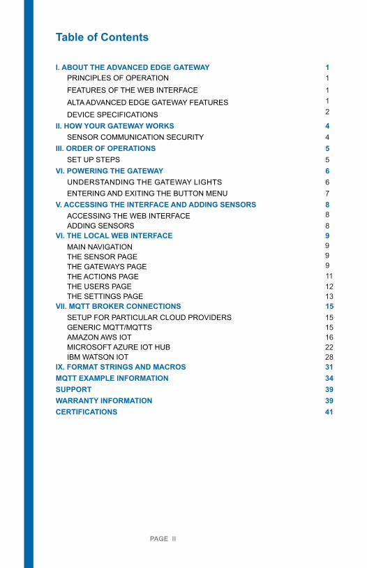
Table of Contents
I. ABOUT THE ADVANCED EDGE GATEWAY 1
FEATURES OF THE WEB INTERFACE1
ALTA ADVANCED EDGE GATEWAY FEATURES1
DEVICE SPECIFICATIONS 2
II. HOW YOUR GATEWAY WORKS 44SENSOR COMMUNICATION SECURITY
III. ORDER OF OPERATIONS 5SET UP STEPS 5
VI. POWERING THE GATEWAY 6UNDERSTANDING THE GATEWAY LIGHTS 6ENTERING AND EXITING THE BUTTON MENU 7
V. ACCESSING THE INTERFACE AND ADDING SENSORS 8ACCESSING THE WEB INTERFACE 8ADDING SENSORS 8
PAGE II
VI. THE LOCAL WEB INTERFACE 9
THE SENSOR PAGE9
THE GATEWAYS PAGE9
THE ACTIONS PAGE9
THE USERS PAGE11
THE SETTINGS PAGE1213
VII. MQTT BROKER CONNECTIONS 15SETUP FOR PARTICULAR CLOUD PROVIDERS 15GENERIC MQTT/MQTTS 15AMAZON AWS IOT 16MICROSOFT AZURE IOT HUB 22IBM WATSON IOT 28
IX. FORMAT STRINGS AND MACROS 3134MQTT EXAMPLE INFORMATION
SUPPORTWARRANTY INFORMATIONCERTIFICATIONS
393941
PRINCIPLES OF OPERATION
1
MAIN NAVIGATION
I. ABOUT THE ADVANCED EDGE GATEWAY
FEATURES OF THE WEB INTERFACE
PAGE 1
ALTA Advanced Edge Gateway is a new, feature rich gateway from Monnit. With ever-in-creasing data generated by billions of “things” that are now part of the Internet of Things, decentralizing the processing of that data to close proximity of the “things” allows for spontaneous analytics, instant action based on monitored metrics and the support of en-hanced situation-based applications. Able to support custom edge based IoT applications the new ALTA Advanced Edge Gateway is ideal for IoT OEMs and ISVs . Additionally, the Advanced Edge Gateway deploys as an MQTTS client, allowing data to be sent to MQTT brokers hosted on platforms such as Amazon AWS, Microsoft Azure, IBM Watson, or to a user’s own broker. The gateway includes a local web interface for configuration. As with all ALTA gateways, this new gateway supports Monnit’s line of 80+ ALTA long range wireless sensors.
Each of these Cloud providers handles IoT data differently, but that’s no problem for the ALTA Edge Gateway. This helpful guide will get you up and running on any platform fast and easy.
ALTA ADVANCED EDGE GATEWAY FEATURES
• Delivery of sensor traffic in a readable format, for most types of Monnit sensors. • Sensor data delivery to multiple cloud providers and/or MQTT brokers.
• Wireless range of 1,200+ feet through 12+ walls *• Frequency Hopping Spread Spectrum (FHSS)• Improved interference immunity• Encrypt-RF® Security (Diffie-Hellman Key Exchange + AES-128 CBC for sensor data
messages)• Up to 5,000 sensor message memory per sensor. • Local status LEDs with transmission and online status indicators• AC power supply
* Actual range may vary depending on environment.
PRINCIPLES OF OPERATION
Monnit’s ALTA Advanced Edge Gateway is a sensor-to-server solution that securely de-livers IoT data to any mainstream cloud provider, such as Amazon AWS, or a proprietary MQTTS server. The device addresses requests for economical hardware that allows rapid deployment of Monnit’s low-cost wireless sensors and direct transmission of sensor data to the cloud.
The Edge Gateway features a custom integrated iMonnit Express 4.0 software for simple sensor network configuration, parameterization (i.e., check-ins and measurement thresh-olds), visualization, and the designation of MQTT brokers. The Ethernet-based gateway is customizable for MQTT topics and message formats; integrated macros permit users to specify their data configuration, e.g., JSON file format. The gateway employs MQTTS to securely collect and transmit data to a designated cloud server(s). The gateway’s integrat-ed macros streamline data management by allowing users to configure data presentation, e.g., JSON or XML.
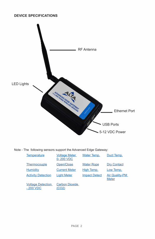
DEVICE SPECIFICATIONS
PAGE 2
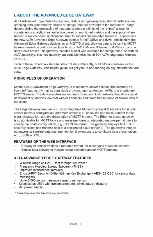
RF Antenna
USB Ports
Ethernet Port
5-12 VDC Power
LED Lights
Note - The following sensors support the Advanced Edge Gateway:
Temperature Voltage Meter 0- 200 VDC
Water Temp. Duct Temp.
Thermocouple Open/Close Water Rope Dry Contact
Humidity Current Meter High Temp. Low Temp.
Activity Detection Light Meter Impact Detect Air Quality-PM Meter
Voltage Detection - 200 VDC
Carbon Dioxide (CO2)
PAGE 3
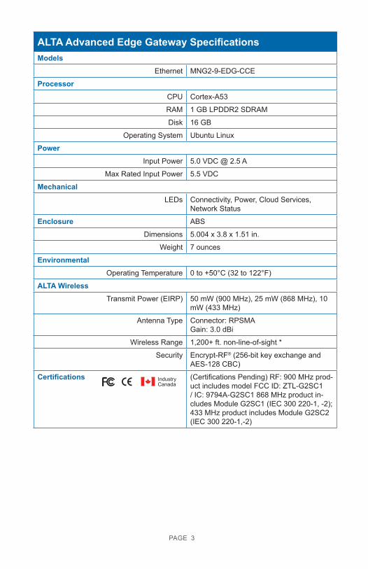
ALTA Advanced Edge Gateway SpecificationsModels
Ethernet MNG2-9-EDG-CCE
ProcessorCPU Cortex-A53
RAM 1 GB LPDDR2 SDRAM
Disk 16 GB
Operating System Ubuntu Linux
PowerInput Power 5.0 VDC @ 2.5 A
Max Rated Input Power 5.5 VDC
MechanicalLEDs Connectivity, Power, Cloud Services,
Network Status
Enclosure ABS
Dimensions 5.004 x 3.8 x 1.51 in.
Weight 7 ounces
EnvironmentalOperating Temperature 0 to +50°C (32 to 122°F)
ALTA WirelessTransmit Power (EIRP) 50 mW (900 MHz), 25 mW (868 MHz), 10
mW (433 MHz)
Antenna Type Connector: RPSMAGain: 3.0 dBi
Wireless Range 1,200+ ft. non-line-of-sight *
Security Encrypt-RF® (256-bit key exchange and AES-128 CBC)
Certifications (Certifications Pending) RF: 900 MHz prod-uct includes model FCC ID: ZTL-G2SC1 / IC: 9794A-G2SC1 868 MHz product in-cludes Module G2SC1 (IEC 300 220-1, -2); 433 MHz product includes Module G2SC2 (IEC 300 220-1,-2)
IndustryCanada
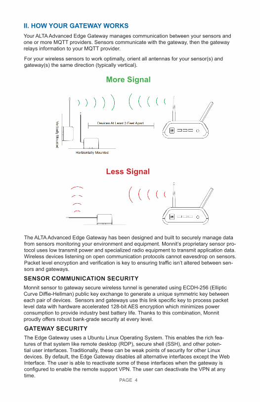
II. HOW YOUR GATEWAY WORKSYour ALTA Advanced Edge Gateway manages communication between your sensors and one or more MQTT providers. Sensors communicate with the gateway, then the gateway relays information to your MQTT provider.
For your wireless sensors to work optimally, orient all antennas for your sensor(s) and gateway(s) the same direction (typically vertical).
More Signal
Less Signal
PAGE 4
The ALTA Advanced Edge Gateway has been designed and built to securely manage data from sensors monitoring your environment and equipment. Monnit’s proprietary sensor pro-tocol uses low transmit power and specialized radio equipment to transmit application data. Wireless devices listening on open communication protocols cannot eavesdrop on sensors. Packet level encryption and verification is key to ensuring traffic isn’t altered between sen-sors and gateways.
GATEWAY SECURITYThe Edge Gateway uses a Ubuntu Linux Operating System. This enables the rich fea-tures of that system like remote desktop (RDP), secure shell (SSH), and other poten-tial user interfaces. Traditionally, these can be weak points of security for other Linux devices. By default, the Edge Gateway disables all alternative interfaces except the Web Interface. The user is able to reactivate some of these interfaces when the gateway is configured to enable the remote support VPN. The user can deactivate the VPN at any time.
SENSOR COMMUNICATION SECURITYMonnit sensor to gateway secure wireless tunnel is generated using ECDH-256 (Elliptic Curve Diffie-Hellman) public key exchange to generate a unique symmetric key between each pair of devices. Sensors and gateways use this link specific key to process packet level data with hardware accelerated 128-bit AES encryption which minimizes power consumption to provide industry best battery life. Thanks to this combination, Monnit proudly offers robust bank-grade security at every level.
III. ORDER OF OPERATIONS
PAGE 5
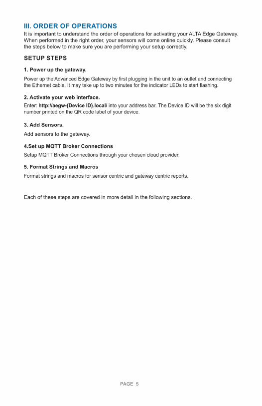
It is important to understand the order of operations for activating your ALTA Edge Gateway. When performed in the right order, your sensors will come online quickly. Please consult the steps below to make sure you are performing your setup correctly.
SETUP STEPS
1. Power up the gateway. Power up the Advanced Edge Gateway by first plugging in the unit to an outlet and connecting the Ethernet cable. It may take up to two minutes for the indicator LEDs to start flashing.
2. Activate your web interface.Enter: http://aegw-{Device ID}.local/ into your address bar. The Device ID will be the six digitnumber printed on the QR code label of your device.
4.Set up MQTT Broker ConnectionsSetup MQTT Broker Connections through your chosen cloud provider.
3. Add Sensors. Add sensors to the gateway.
Each of these steps are covered in more detail in the following sections.
5. Format Strings and MacrosFormat strings and macros for sensor centric and gateway centric reports.
PAGE 6
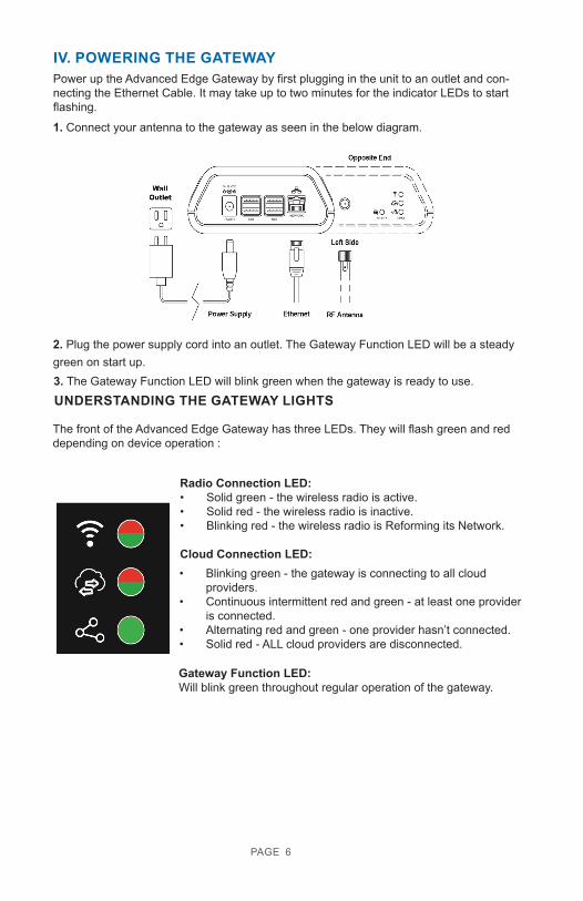
IV. POWERING THE GATEWAYPower up the Advanced Edge Gateway by first plugging in the unit to an outlet and con-necting the Ethernet Cable. It may take up to two minutes for the indicator LEDs to start flashing.
1. Connect your antenna to the gateway as seen in the below diagram.
2. Plug the power supply cord into an outlet. The Gateway Function LED will be a steady green on start up. 3. The Gateway Function LED will blink green when the gateway is ready to use. UNDERSTANDING THE GATEWAY LIGHTS
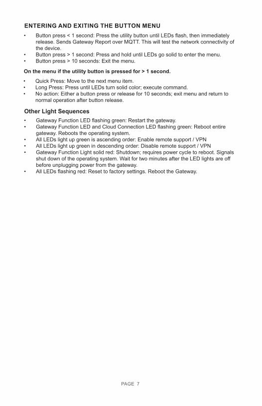
The front of the Advanced Edge Gateway has three LEDs. They will flash green and red depending on device operation :
Radio Connection LED: • Solid green - the wireless radio is active.• Solid red - the wireless radio is inactive. • Blinking red - the wireless radio is Reforming its Network.
Cloud Connection LED:
Gateway Function LED: Will blink green throughout regular operation of the gateway.
• Blinking green - the gateway is connecting to all cloud providers.
• Continuous intermittent red and green - at least one provider is connected.
• Alternating red and green - one provider hasn’t connected.• Solid red - ALL cloud providers are disconnected.
PAGE 7
ENTERING AND EXITING THE BUTTON MENU• Button press < 1 second: Press the utility button until LEDs flash, then immediately
release. Sends Gateway Report over MQTT. This will test the network connectivity of the device.
• Button press > 1 second: Press and hold until LEDs go solid to enter the menu. • Button press > 10 seconds: Exit the menu.
On the menu if the utility button is pressed for > 1 second.
• Quick Press: Move to the next menu item. • Long Press: Press until LEDs turn solid color; execute command. • No action: Either a button press or release for 10 seconds; exit menu and return to
normal operation after button release.
• Gateway Function LED flashing green: Restart the gateway.• Gateway Function LED and Cloud Connection LED flashing green: Reboot entire
gateway. Reboots the operating system.• All LEDs light up green is ascending order: Enable remote support / VPN• All LEDs light up green in descending order: Disable remote support / VPN• Gateway Function Light solid red: Shutdown; requires power cycle to reboot. Signals
shut down of the operating system. Wait for two minutes after the LED lights are off before unplugging power from the gateway.
• All LEDs flashing red: Reset to factory settings. Reboot the Gateway.
Other Light Sequences
PAGE 8
V. ACCESSING THE INTERFACE AND ADDING SENSORSACCESSING THE WEB INTERFACE
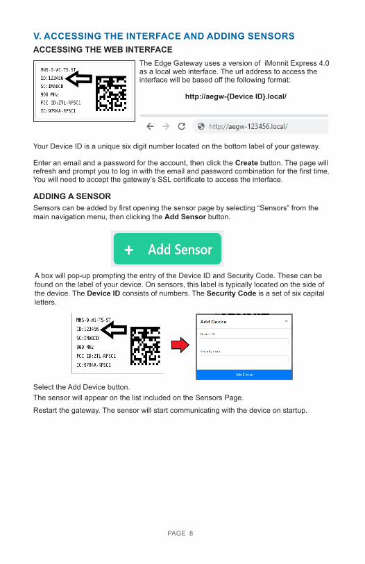
The Edge Gateway uses a version of iMonnit Express 4.0 as a local web interface. The url address to access the interface will be based off the following format:
http://aegw-{Device ID}.local/
Your Device ID is a unique six digit number located on the bottom label of your gateway.
Enter an email and a password for the account, then click the Create button. The page will refresh and prompt you to log in with the email and password combination for the first time. You will need to accept the gateway’s SSL certificate to access the interface.
ADDING A SENSORSensors can be added by first opening the sensor page by selecting “Sensors” from the main navigation menu, then clicking the Add Sensor button.
A box will pop-up prompting the entry of the Device ID and Security Code. These can be found on the label of your device. On sensors, this label is typically located on the side of the device. The Device ID consists of numbers. The Security Code is a set of six capital letters.
Select the Add Device button. The sensor will appear on the list included on the Sensors Page.
Restart the gateway. The sensor will start communicating with the device on startup.
PAGE 9
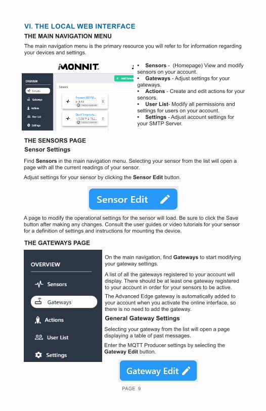
VI. THE LOCAL WEB INTERFACETHE MAIN NAVIGATION MENUThe main navigation menu is the primary resource you will refer to for information regarding your devices and settings.
• Sensors - (Homepage) View and modify sensors on your account. • Gateways - Adjust settings for your gateways. • Actions - Create and edit actions for your sensors. • User List- Modify all permissions and settings for users on your account. • Settings - Adjust account settings for your SMTP Server.
Sensor Settings
Find Sensors in the main navigation menu. Selecting your sensor from the list will open a page with all the current readings of your sensor.
Adjust settings for your sensor by clicking the Sensor Edit button.
A page to modify the operational settings for the sensor will load. Be sure to click the Save button after making any changes. Consult the user guides or video tutorials for your sensor for a definition of settings and instructions for mounting the device.
THE GATEWAYS PAGE
On the main navigation, find Gateways to start modifying your gateway settings.
A list of all the gateways registered to your account will display. There should be at least one gateway registered to your account in order for your sensors to be active. The Advanced Edge gateway is automatically added to your account when you activate the online interface, so there is no need to add the gateway.
General Gateway SettingsSelecting your gateway from the list will open a page displaying a table of past messages.
THE SENSORS PAGE
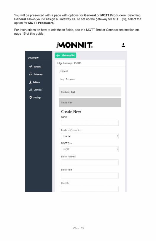
Enter the MQTT Producer settings by selecting the Gateway Edit button.
PAGE 10
You will be presented with a page with options for General or MQTT Producers. Selecting General allows you to assign a Gateway ID. To set up the gateway for MQTT(S), select the option for MQTT Producers.
For instructions on how to edit these fields, see the MQTT Broker Connections section on page 15 of this guide.
PAGE 11
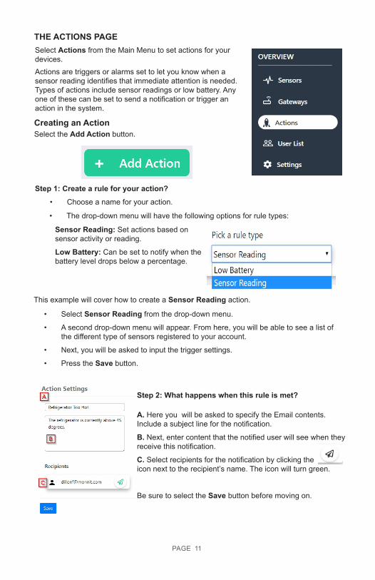
THE ACTIONS PAGE
Actions are triggers or alarms set to let you know when a sensor reading identifies that immediate attention is needed. Types of actions include sensor readings or low battery. Any one of these can be set to send a notification or trigger an action in the system.
Select Actions from the Main Menu to set actions for your devices.
Creating an ActionSelect the Add Action button.
• The drop-down menu will have the following options for rule types:
Sensor Reading: Set actions based on sensor activity or reading.
Low Battery: Can be set to notify when the battery level drops below a percentage.
• Select Sensor Reading from the drop-down menu.
• A second drop-down menu will appear. From here, you will be able to see a list of the different type of sensors registered to your account.
• Next, you will be asked to input the trigger settings.
• Press the Save button.
Step 1: Create a rule for your action?
Step 2: What happens when this rule is met?
A. Here you will be asked to specify the Email contents. Include a subject line for the notification.
B. Next, enter content that the notified user will see when they receive this notification.
C. Select recipients for the notification by clicking the icon next to the recipient’s name. The icon will turn green.
Be sure to select the Save button before moving on.
• Choose a name for your action.
This example will cover how to create a Sensor Reading action.
PAGE 12
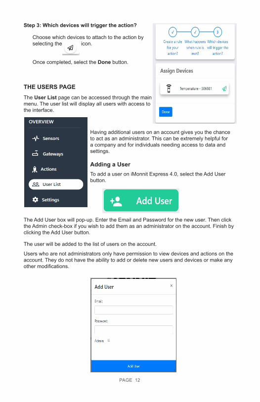
Step 3: Which devices will trigger the action?
Choose which devices to attach to the action by selecting the icon.
Once completed, select the Done button.
The User List page can be accessed through the main menu. The user list will display all users with access to the interface.
Having additional users on an account gives you the chance to act as an administrator. This can be extremely helpful for a company and for individuals needing access to data and settings.
Adding a UserTo add a user on iMonnit Express 4.0, select the Add User button.
The Add User box will pop-up. Enter the Email and Password for the new user. Then click the Admin check-box if you wish to add them as an administrator on the account. Finish by clicking the Add User button.
The user will be added to the list of users on the account.
Users who are not administrators only have permission to view devices and actions on the account. They do not have the ability to add or delete new users and devices or make any other modifications.
THE USERS PAGE
PAGE 13
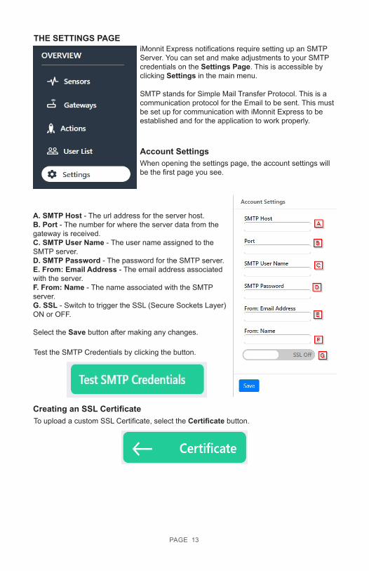
THE SETTINGS PAGEiMonnit Express notifications require setting up an SMTP Server. You can set and make adjustments to your SMTP credentials on the Settings Page. This is accessible by clicking Settings in the main menu.
SMTP stands for Simple Mail Transfer Protocol. This is a communication protocol for the Email to be sent. This must be set up for communication with iMonnit Express to be established and for the application to work properly.
Account SettingsWhen opening the settings page, the account settings will be the first page you see.
A. SMTP Host - The url address for the server host. B. Port - The number for where the server data from the gateway is received. C. SMTP User Name - The user name assigned to the SMTP server. D. SMTP Password - The password for the SMTP server. E. From: Email Address - The email address associated with the server. F. From: Name - The name associated with the SMTP server. G. SSL - Switch to trigger the SSL (Secure Sockets Layer) ON or OFF.
Select the Save button after making any changes.
Creating an SSL CertificateTo upload a custom SSL Certificate, select the Certificate button.
Test the SMTP Credentials by clicking the button.
PAGE 14
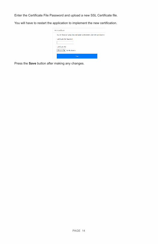
Enter the Certificate File Password and upload a new SSL Certificate file.
You will have to restart the application to implement the new certification.
Press the Save button after making any changes.
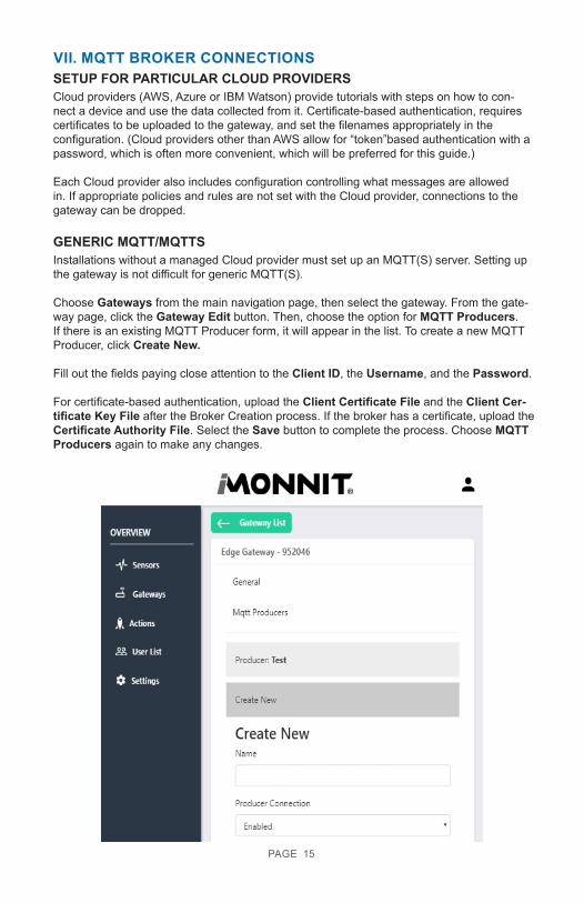
VII. MQTT BROKER CONNECTIONS
PAGE 15
Cloud providers (AWS, Azure or IBM Watson) provide tutorials with steps on how to con-nect a device and use the data collected from it. Certificate-based authentication, requires certificates to be uploaded to the gateway, and set the filenames appropriately in the configuration. (Cloud providers other than AWS allow for “token”based authentication with a password, which is often more convenient, which will be preferred for this guide.)
Each Cloud provider also includes configuration controlling what messages are allowed in. If appropriate policies and rules are not set with the Cloud provider, connections to the gateway can be dropped.
SETUP FOR PARTICULAR CLOUD PROVIDERS
Installations without a managed Cloud provider must set up an MQTT(S) server. Setting up the gateway is not difficult for generic MQTT(S).
Choose Gateways from the main navigation page, then select the gateway. From the gate-way page, click the Gateway Edit button. Then, choose the option for MQTT Producers. If there is an existing MQTT Producer form, it will appear in the list. To create a new MQTT Producer, click Create New.
Fill out the fields paying close attention to the Client ID, the Username, and the Password.
For certificate-based authentication, upload the Client Certificate File and the Client Cer-tificate Key File after the Broker Creation process. If the broker has a certificate, upload the Certificate Authority File. Select the Save button to complete the process. Choose MQTT Producers again to make any changes.
GENERIC MQTT/MQTTS
PAGE 16
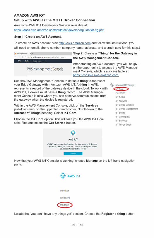
AMAZON AWS IOTSetup with AWS as the MQTT Broker ConnectionAmazon’s AWS IOT Developers Guide is available at: https://docs.aws.amazon.com/iot/latest/developerguide/iot-dg.pdf
Step 1: Create an AWS Account.
To create an AWS account, visit http://aws.amazon.com and follow the instructions. (You will need an email, phone number, company name, address, and a credit card for this step.)
Step 2: Create a “Thing” for the Gateway in the AWS Management Console.
After creating an AWS account, you will be giv-en the opportunity to access the AWS Manage-ment Console, which is also available at: https://console.aws.amazon.com.
Use the AWS Management Console to define a thing to represent your Edge Gateway within Amazon AWS IoT. A thing in AWS, represents a record of the gateway device in the cloud. To work with AWS IoT, a device must have a thing record. The AWS Manage-ment Console is also where you can observe communications from the gateway when the device is registered.
Within the AWS Management Console, click on the Services pull-down menu in the upper left-hand corner. Scroll down to the Internet of Things heading. Select IoT Core.
Choose the IoT Core option. This will take you the AWS IoT Con-sole. Find and select the Get Started button.
Now that your AWS IoT Console is working, choose Manage on the left-hand navigation pane.
Locate the “you don’t have any things yet” section. Choose the Register a thing button.
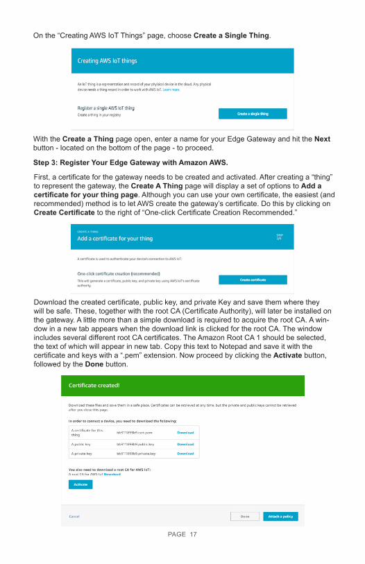
On the “Creating AWS IoT Things” page, choose Create a Single Thing.
With the Create a Thing page open, enter a name for your Edge Gateway and hit the Next button - located on the bottom of the page - to proceed.
Step 3: Register Your Edge Gateway with Amazon AWS.
First, a certificate for the gateway needs to be created and activated. After creating a “thing” to represent the gateway, the Create A Thing page will display a set of options to Add a certificate for your thing page. Although you can use your own certificate, the easiest (and recommended) method is to let AWS create the gateway’s certificate. Do this by clicking on Create Certificate to the right of “One-click Certificate Creation Recommended.”
Download the created certificate, public key, and private Key and save them where they will be safe. These, together with the root CA (Certificate Authority), will later be installed on the gateway. A little more than a simple download is required to acquire the root CA. A win-dow in a new tab appears when the download link is clicked for the root CA. The window includes several different root CA certificates. The Amazon Root CA 1 should be selected, the text of which will appear in new tab. Copy this text to Notepad and save it with the certificate and keys with a “.pem” extension. Now proceed by clicking the Activate button, followed by the Done button.
PAGE 17
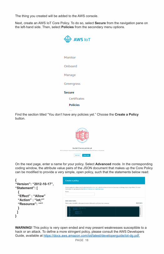
The thing you created will be added to the AWS console.
Next, create an AWS IoT Core Policy. To do so, select Secure from the navigation pane on the left-hand side. Then, select Policies from the secondary menu options.
Find the section titled “You don’t have any policies yet.” Choose the Create a Policy button.
On the next page, enter a name for your policy. Select Advanced mode. In the corresponding coding window, the attribute value pairs of the JSON document that makes up the Core Policy can be modified to provide a very simple, open policy, such that the statements below read:
{“Version”: “2012-10-17”,“Statement”: [ { “Effect” : “Allow” “Action” : “iot;*” “Resource”: “*” } ]}
WARNING! This policy is very open ended and may present weaknesses susceptible to a hack or an attack. To define a more stringent policy, please consult the AWS Developers Guide, available at https://docs.aws.amazon.com/iot/latest/developerguide/iot-dg.pdf.
PAGE 18
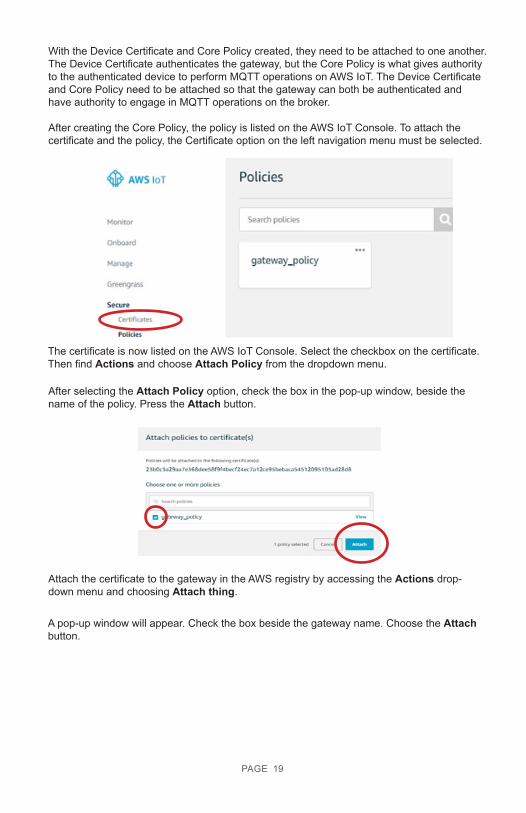
With the Device Certificate and Core Policy created, they need to be attached to one another. The Device Certificate authenticates the gateway, but the Core Policy is what gives authority to the authenticated device to perform MQTT operations on AWS IoT. The Device Certificate and Core Policy need to be attached so that the gateway can both be authenticated and have authority to engage in MQTT operations on the broker.
After creating the Core Policy, the policy is listed on the AWS IoT Console. To attach the certificate and the policy, the Certificate option on the left navigation menu must be selected.
The certificate is now listed on the AWS IoT Console. Select the checkbox on the certificate. Then find Actions and choose Attach Policy from the dropdown menu.
After selecting the Attach Policy option, check the box in the pop-up window, beside the name of the policy. Press the Attach button.
Attach the certificate to the gateway in the AWS registry by accessing the Actions drop-down menu and choosing Attach thing.
A pop-up window will appear. Check the box beside the gateway name. Choose the Attach button.
PAGE 19
The certificate and private authentication key together with other configurations need to be installed on the gateway. Do so by opening the iMonnit Express 4.0 online interface in a browser window. See page 8 of this guide.
Step 4: Load the Certificate and Private Authentication Key on the Gateway
Go to the MQTT Producers page. See page 15 of this guide for instructions.
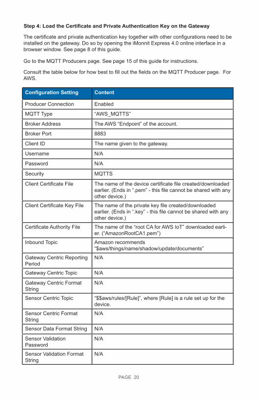
Consult the table below for how best to fill out the fields on the MQTT Producer page. For AWS.
Configuration Setting Content
Producer Connection Enabled
MQTT Type “AWS_MQTTS”
Broker Address The AWS “Endpoint” of the account.
Broker Port 8883
Client ID The name given to the gateway.
Username N/A
Password N/A
Security MQTTS
Client Certificate File The name of the device certificate file created/downloaded earlier. (Ends in “.pem” - this file cannot be shared with any other device.)
Client Certificate Key File The name of the private key file created/downloaded earlier. (Ends in “.key” - this file cannot be shared with any other device.)
Certificate Authority File The name of the “root CA for AWS IoT” downloaded earli-er. (“AmazonRootCA1.pem”)
Inbound Topic Amazon recommends“$aws/things/name/shadow/update/documents”
Gateway Centric ReportingPeriod
N/A
Gateway Centric Topic N/A
Gateway Centric Format String
N/A
Sensor Centric Topic “$$aws/rules/[Rule]”, where [Rule] is a rule set up for the device.
Sensor Centric Format String
N/A
Sensor Data Format String N/A
Sensor Validation Password
N/A
Sensor Validation Format String
N/A
PAGE 20
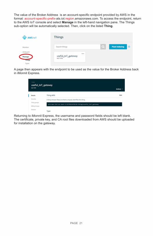
The value of the Broker Address is an account-specific endpoint provided by AWS in the format: account-specific-prefix-ats.iot.region.amazonaws.com. To access the endpoint, return to the AWS IoT console and select Manage in the left-hand navigation pane. The Things sub-option will be automatically selected. Then, click on the listed Thing.
A page then appears with the endpoint to be used as the value for the Broker Address back in iMonnit Express.
Returning to iMonnit Express, the username and password fields should be left blank. The certificate, private key, and CA root files downloaded from AWS should be uploaded for installation on the gateway.
PAGE 21
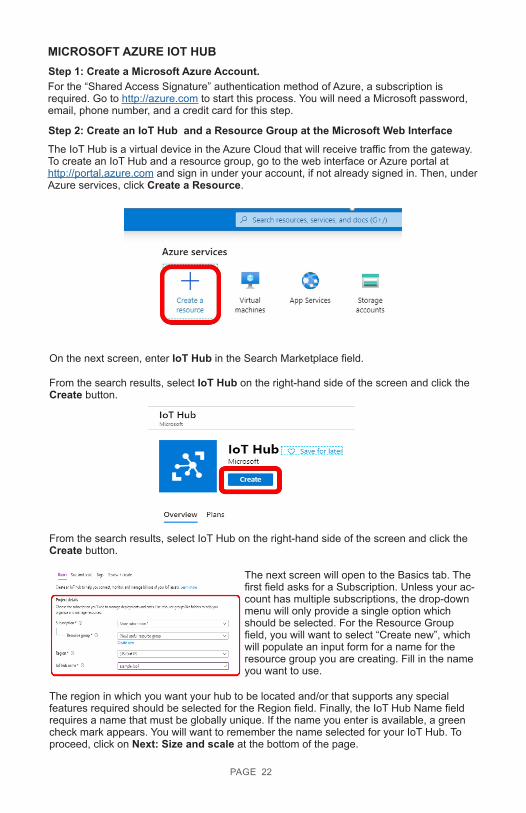
MICROSOFT AZURE IOT HUBStep 1: Create a Microsoft Azure Account. For the “Shared Access Signature” authentication method of Azure, a subscription is required. Go to http://azure.com to start this process. You will need a Microsoft password, email, phone number, and a credit card for this step.
Step 2: Create an IoT Hub and a Resource Group at the Microsoft Web InterfaceThe IoT Hub is a virtual device in the Azure Cloud that will receive traffic from the gateway. To create an IoT Hub and a resource group, go to the web interface or Azure portal at http://portal.azure.com and sign in under your account, if not already signed in. Then, under Azure services, click Create a Resource.
On the next screen, enter IoT Hub in the Search Marketplace field.
From the search results, select IoT Hub on the right-hand side of the screen and click the Create button.
From the search results, select IoT Hub on the right-hand side of the screen and click the Create button.
The next screen will open to the Basics tab. The first field asks for a Subscription. Unless your ac-count has multiple subscriptions, the drop-down menu will only provide a single option which should be selected. For the Resource Group field, you will want to select “Create new”, which will populate an input form for a name for the resource group you are creating. Fill in the name you want to use.
The region in which you want your hub to be located and/or that supports any special features required should be selected for the Region field. Finally, the IoT Hub Name field requires a name that must be globally unique. If the name you enter is available, a green check mark appears. You will want to remember the name selected for your IoT Hub. To proceed, click on Next: Size and scale at the bottom of the page.
PAGE 22
Unless application specific needs require otherwise, the default settings on the next page can all be accepted. As can be seen, links to additional information about these settings are available here. When satisfied with the settings on this page, select Next:Tags to continue.
Tags are name/value pairs that can be assigned to multiple resources to categorize re-sources and consolidate billing. With the tags set, press the Review + Create button.
Review settings on the next screen and select the Create button.
The IoT Hub has been successfully deployed. Now that the hub and resource group have been created, an IoT device needs to be created to represent the gateway so the IoT Hub can receive traffic from the gateway.
Step 3: Create an IoT Device for the Gateway.
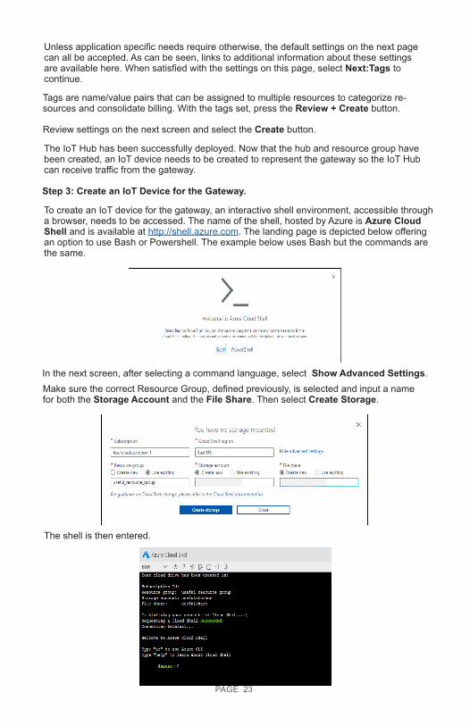
To create an IoT device for the gateway, an interactive shell environment, accessible through a browser, needs to be accessed. The name of the shell, hosted by Azure is Azure Cloud Shell and is available at http://shell.azure.com. The landing page is depicted below offering an option to use Bash or Powershell. The example below uses Bash but the commands are the same.
In the next screen, after selecting a command language, select Show Advanced Settings.Make sure the correct Resource Group, defined previously, is selected and input a name for both the Storage Account and the File Share. Then select Create Storage.
The shell is then entered.
PAGE 23
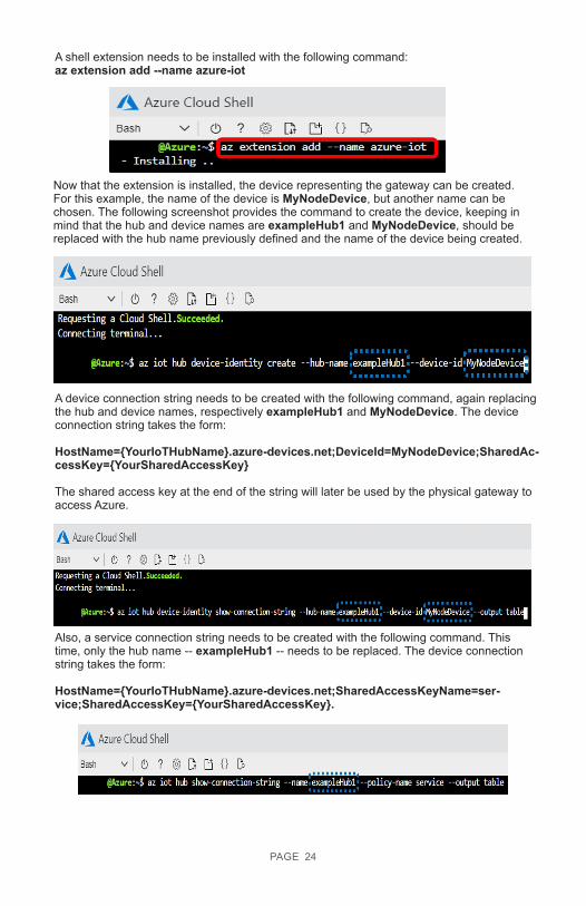
A shell extension needs to be installed with the following command:az extension add --name azure-iot
Now that the extension is installed, the device representing the gateway can be created. For this example, the name of the device is MyNodeDevice, but another name can be chosen. The following screenshot provides the command to create the device, keeping in mind that the hub and device names are exampleHub1 and MyNodeDevice, should be replaced with the hub name previously defined and the name of the device being created.
A device connection string needs to be created with the following command, again replacing the hub and device names, respectively exampleHub1 and MyNodeDevice. The device connection string takes the form:
HostName={YourIoTHubName}.azure-devices.net;DeviceId=MyNodeDevice;SharedAc-cessKey={YourSharedAccessKey}
The shared access key at the end of the string will later be used by the physical gateway to access Azure.
Also, a service connection string needs to be created with the following command. This time, only the hub name -- exampleHub1 -- needs to be replaced. The device connection string takes the form:
HostName={YourIoTHubName}.azure-devices.net;SharedAccessKeyName=ser-vice;SharedAccessKey={YourSharedAccessKey}.
PAGE 24
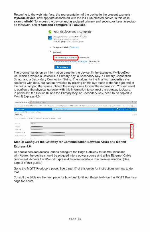
Returning to the web interface, the representation of the device in the present example - MyNodeDevice, now appears associated with the IoT Hub created earlier, in this case, exampleHub1.To access the device and associated primary and secondary keys associat-ed therewith, select Add and configure IoT Devices.
The browser lands on an information page for the device, in the example, MyNodeDev-ice, which provides a DeviceID, a Primary Key, a Secondary Key, a Primary Connection String, and a Secondary Connection String. The values for the final four properties are obscured with dots, but can be revealed by clicking on the eye icons to the far-right end of the fields carrying the values. Select these eye icons to view the information. You will need to configure the physical gateway with this information to connect the gateway to Azure. In particular, the Device ID and the Primary Key, or Secondary Key, need to be copied to Monnit Express 4.0.
Step 4: Configure the Gateway for Communication Between Azure and Monnit Express 4.0.
To enable secured access, and to configure the Edge Gateway for communications with Azure, the device should be plugged into a power source and a live Ethernet Cable connected. Access the iMonnit Express 4.0 online interface in a browser window. (See page 8 of this guide.)
Go to the MQTT Producers page. See page 17 of this guide for instructions on how to do that.
Consult the table on the next page for how best to fill out these fields on the MQTT Producer page for Azure.
PAGE 25
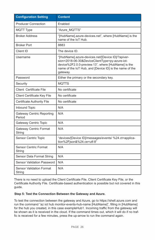
Configuration Setting Content
Producer Connection Enabled
MQTT Type “Azure_MQTTS”
Broker Address “[HubName].azure-devices.net”, where [HubName] is the name of the IoT Hub.
Broker Port 8883
Client ID The device ID.
Username “[HubName].azure-devices.net/[Device ID]/?apiver-sion=2018-06-30&DeviceClientType=py-azure-iot-device%2F2.0.0-preview.13”, where [HubName] is the name of the IoT Hub, and [Device ID] is the name of the gateway.
Password Either the primary or the secondary key.
Security MQTTS
Client Certificate File No certificate
Client Certificate Key File No certificate
Certificate Authority File No certificate
Inbound Topic N/A
Gateway Centric Reporting Period
N/A
Gateway Centric Topic N/A
Gateway Centric Format String
N/A
Sensor Centric Topic “devices/[Device ID]/messages/events/ %24.ct=applica-tion%2Fjson&%24.ce=utf-8”
Sensor Centric Format String
N/A
Sensor Data Format String N/A
Sensor Validation Password N/A
Sensor Validation FormatString
N/A
There is no need to upload the Client Certificate File, Client Certificate Key File, or the Certificate Authority File. Certificate-based authentication is possible but not covered in this guide.
Step 5: Test the Connection Between the Gateway and Azure.
To test the connection between the gateway and Azure, go to https://shell.azure.com and run the command “az iot hub monitor-events-hub-name [HubName]”, filling in [HubName] for the hub you created, in this case exampleHub1. Incoming traffic from the gateway will be shown as it is received in the cloud. If the command times out, which it will do if no traf-fic is received for a few minutes, press the up-arrow to run the command again.
PAGE 26
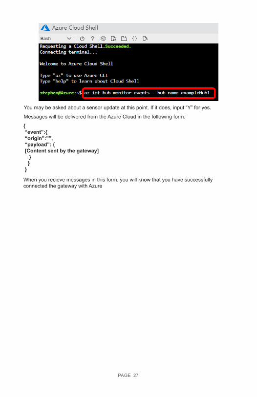
You may be asked about a sensor update at this point. If it does, input “Y” for yes.
Messages will be delivered from the Azure Cloud in the following form:
{ “event”:{ “origin”:””, “payload”: { [Content sent by the gateway] } } }
When you recieve messages in this form, you will know that you have successfully connected the gateway with Azure
PAGE 27
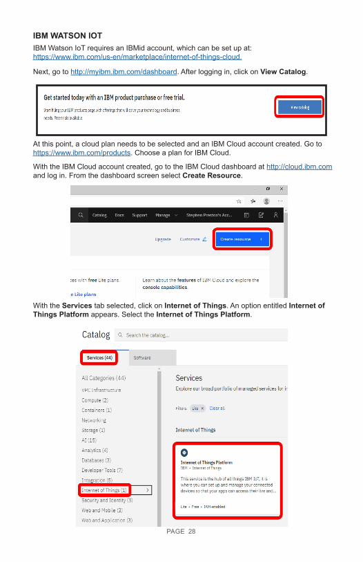
IBM Watson IoT requires an IBMid account, which can be set up at:https://www.ibm.com/us-en/marketplace/internet-of-things-cloud.
IBM WATSON IOT
Next, go to http://myibm.ibm.com/dashboard. After logging in, click on View Catalog.
At this point, a cloud plan needs to be selected and an IBM Cloud account created. Go to https://www.ibm.com/products. Choose a plan for IBM Cloud.
With the IBM Cloud account created, go to the IBM Cloud dashboard at http://cloud.ibm.com and log in. From the dashboard screen select Create Resource.
With the Services tab selected, click on Internet of Things. An option entitled Internet of Things Platform appears. Select the Internet of Things Platform.
PAGE 28
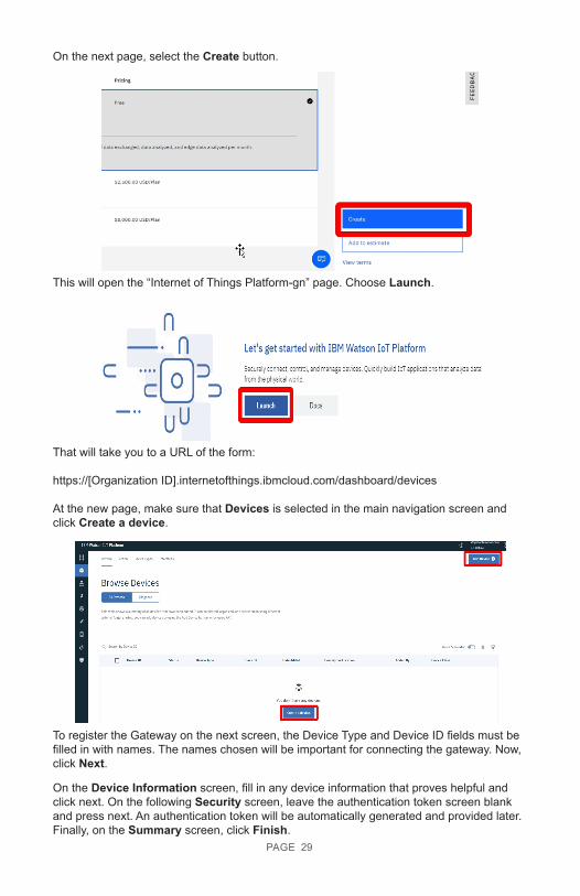
On the next page, select the Create button.
This will open the “Internet of Things Platform-gn” page. Choose Launch.
That will take you to a URL of the form:
https://[Organization ID].internetofthings.ibmcloud.com/dashboard/devices
At the new page, make sure that Devices is selected in the main navigation screen and click Create a device.
To register the Gateway on the next screen, the Device Type and Device ID fields must be filled in with names. The names chosen will be important for connecting the gateway. Now, click Next.
PAGE 29
On the Device Information screen, fill in any device information that proves helpful and click next. On the following Security screen, leave the authentication token screen blank and press next. An authentication token will be automatically generated and provided later. Finally, on the Summary screen, click Finish.
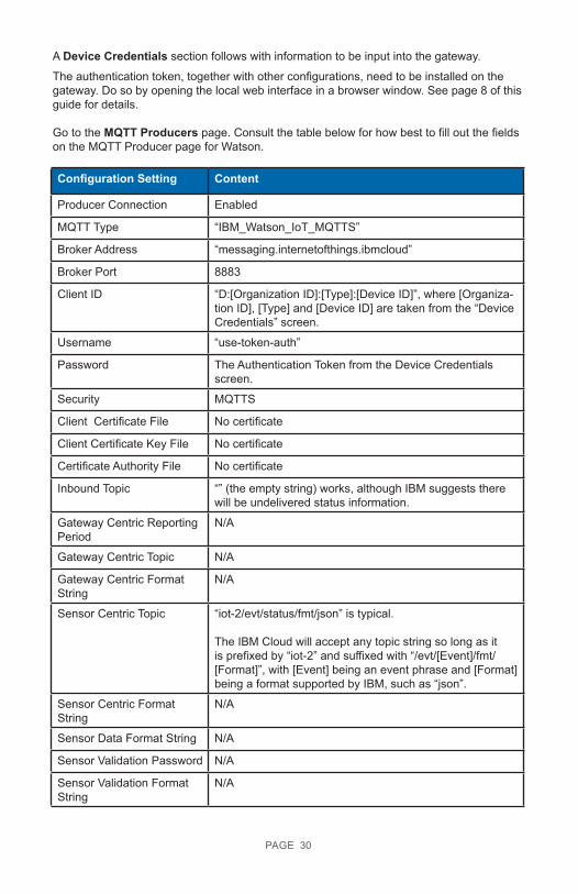
A Device Credentials section follows with information to be input into the gateway.
The authentication token, together with other configurations, need to be installed on the gateway. Do so by opening the local web interface in a browser window. See page 8 of this guide for details.
Go to the MQTT Producers page. Consult the table below for how best to fill out the fields on the MQTT Producer page for Watson.
Configuration Setting Content
Producer Connection Enabled
MQTT Type “IBM_Watson_IoT_MQTTS”
Broker Address “messaging.internetofthings.ibmcloud”
Broker Port 8883
Client ID “D:[Organization ID]:[Type]:[Device ID]”, where [Organiza-tion ID], [Type] and [Device ID] are taken from the “Device Credentials” screen.
Username “use-token-auth”
Password The Authentication Token from the Device Credentials screen.
Security MQTTS
Client Certificate File No certificate
Client Certificate Key File No certificate
Certificate Authority File No certificate
Inbound Topic “” (the empty string) works, although IBM suggests there will be undelivered status information.
Gateway Centric Reporting Period
N/A
Gateway Centric Topic N/A
Gateway Centric Format String
N/A
Sensor Centric Topic “iot-2/evt/status/fmt/json” is typical.
The IBM Cloud will accept any topic string so long as it is prefixed by “iot-2” and suffixed with “/evt/[Event]/fmt/[Format]”, with [Event] being an event phrase and [Format] being a format supported by IBM, such as “json”.
Sensor Centric Format String
N/A
Sensor Data Format String N/A
Sensor Validation Password N/A
Sensor Validation Format String
N/A
PAGE 30
PAGE 31
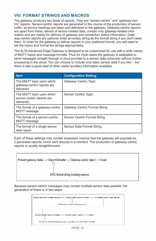
VIII. FORMAT STRINGS AND MACROSThe gateway produces two kinds of reports. They are “sensor-centric” and “gateway-cen-tric” reports. Sensor-centric reports are generated in the course of the production of sensor traffic, as sensor readings are taken and delivered to the gateway. Gateway-centric reports are apart from these, devoid of sensor-related data, contain only gateway-related infor-mation and are mainly for delivery of gateway and connection status information. Gate-way-centric reports are optional: enter an empty string as the format string if you don't need them. In order for the gateway to deliver reports in your preferred format, you will need to set the topics and format the strings appropriately.
The ALTA Advanced Edge Gateway is designed to be customized for use with a wide variety of MQTT topics and message formats. Thus for most cases the gateway is adaptable to send messages straight through a cloud provider to a sensor data consumer without further processing in the cloud. You can choose to include only basic sensor data if you like -- but there is also a good deal of other useful ancillary information available.
Item Configuration Setting
The MQTT topic upon which gateway-centric reports are delivered.
Gateway Centric Topic
The MQTT topic upon which sensor centric reports are delivered.
Sensor Centric Topic
The format of a gateway-centric MQTT message
Gateway Centric Format String
The format of a sensor-centric MQTT message
Sensor Centric Format String
The format of a single sensor data report.
Sensor Data Format String
Each of these settings may contain expansion macros that the gateway will populate as it generates reports, which we'll discuss in a moment. The production of gateway-centric reports is usually straightforward:
Because sensor-centric messages may contain multiple sensor data packets, the generation of these is in two steps:
PAGE 32
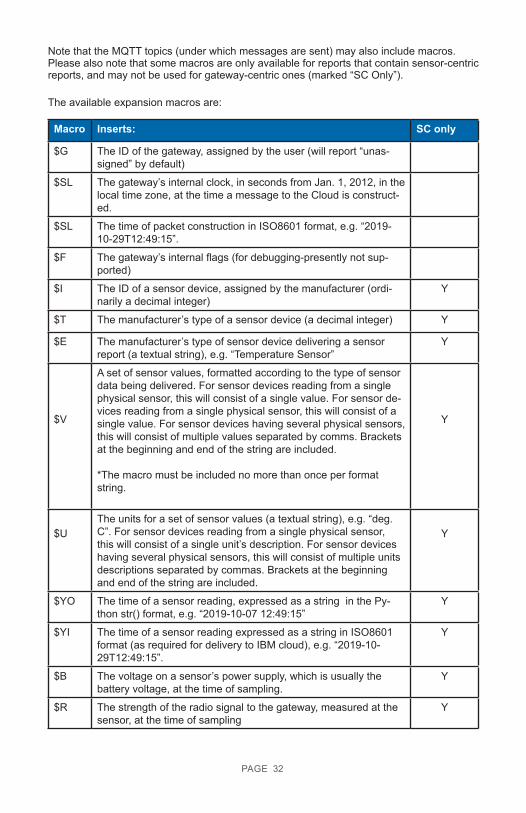
Note that the MQTT topics (under which messages are sent) may also include macros. Please also note that some macros are only available for reports that contain sensor-centric reports, and may not be used for gateway-centric ones (marked “SC Only”).
The available expansion macros are:
Macro Inserts: SC only
$G The ID of the gateway, assigned by the user (will report “unas-signed” by default)
$SL The gateway’s internal clock, in seconds from Jan. 1, 2012, in the local time zone, at the time a message to the Cloud is construct-ed.
$SL The time of packet construction in ISO8601 format, e.g. “2019-10-29T12:49:15”.
$F The gateway’s internal flags (for debugging-presently not sup-ported)
$I The ID of a sensor device, assigned by the manufacturer (ordi-narily a decimal integer)
Y
$T The manufacturer’s type of a sensor device (a decimal integer) Y
$E The manufacturer’s type of sensor device delivering a sensor report (a textual string), e.g. “Temperature Sensor”
Y
$V
A set of sensor values, formatted according to the type of sensor data being delivered. For sensor devices reading from a single physical sensor, this will consist of a single value. For sensor de-vices reading from a single physical sensor, this will consist of a single value. For sensor devices having several physical sensors, this will consist of multiple values separated by comms. Brackets at the beginning and end of the string are included.
*The macro must be included no more than once per format string.
Y
$UThe units for a set of sensor values (a textual string), e.g. “deg. C”. For sensor devices reading from a single physical sensor, this will consist of a single unit’s description. For sensor devices having several physical sensors, this will consist of multiple units descriptions separated by commas. Brackets at the beginning and end of the string are included.
Y
$YO The time of a sensor reading, expressed as a string in the Py-thon str() format, e.g. “2019-10-07 12:49:15”
Y
$YI The time of a sensor reading expressed as a string in ISO8601 format (as required for delivery to IBM cloud), e.g. “2019-10-29T12:49:15”.
Y
$B The voltage on a sensor’s power supply, which is usually the battery voltage, at the time of sampling.
Y
$R The strength of the radio signal to the gateway, measured at the sensor, at the time of sampling
Y
PAGE 33
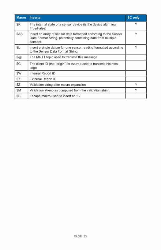
Macro Inserts: SC only
$K The internal state of a sensor device (is the device alarming, True/False)
Y
$AS Insert an array of sensor data formatted according to the Sensor Data Format String, potentially containing data from multiple sensors.
Y
$L Insert a single datum for one sensor reading formatted according to the Sensor Data Format String.
Y
$@ The MQTT topic used to transmit this message
$C The client ID (the “origin” for Azure) used to transmit this mes-sage
$W Internal Report ID
$X External Report ID
$Z Validation string after macro expansion Y
$M Validation stamp as computed from the validation string. Y
$S Escape macro used to insert an “S”
PAGE 34
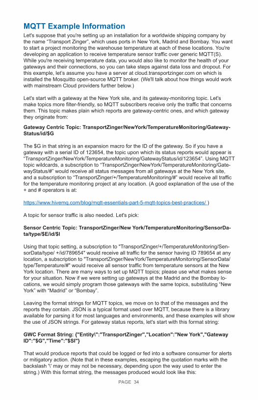
MQTT Example InformationLet's suppose that you're setting up an installation for a worldwide shipping company by the name “Transport Zinger”, which uses ports in New York, Madrid and Bombay. You want to start a project monitoring the warehouse temperature at each of these locations. You're developing an application to receive temperature sensor traffic over generic MQTT(S). While you're receiving temperature data, you would also like to monitor the health of your gateways and their connections, so you can take steps against data loss and dropout. For this example, let’s assume you have a server at cloud.transportzinger.com on which is installed the Mosquitto open-source MQTT broker. (We'll talk about how things would work with mainstream Cloud providers further below.)
Let's start with a gateway at the New York site, and its gateway-monitoring topic. Let's make topics more filter-friendly, so MQTT subscribers receive only the traffic that concerns them. This topic makes plain which reports are gateway-centric ones, and which gateway they originate from:
Gateway Centric Topic: TransportZinger/NewYork/TemperatureMonitoring/Gateway-Status/id/$G
The $G in that string is an expansion macro for the ID of the gateway. So if you have a gateway with a serial ID of 123654, the topic upon which its status reports would appear is “TransportZinger/NewYork/TemperatureMonitoring/GatewayStatus/id/123654”. Using MQTT topic wildcards, a subscription to “TransportZinger/NewYork/TemperatureMonitoring/Gate-wayStatus/#” would receive all status messages from all gateways at the New York site, and a subscription to “TransportZinger/+/TemperatureMonitoring/#” would receive all traffic for the temperature monitoring project at any location. (A good explanation of the use of the + and # operators is at:
https://www.hivemq.com/blog/mqtt-essentials-part-5-mqtt-topics-best-practices/ )
A topic for sensor traffic is also needed. Let's pick:
Sensor Centric Topic: TransportZinger/New York/TemperatureMonitoring/SensorDa-ta/type/$E/id/$I
Using that topic setting, a subscription to "TransportZinger/+/TemperatureMonitoring/Sen-sorData/type/ +/id/789654" would receive all traffic for the sensor having ID 789654 at any location, a subscription to "TransportZinger/NewYork/TemperatureMonitoring/SensorData/type/Temperature/#" would receive all sensor traffic from temperature sensors at the New York location. There are many ways to set up MQTT topics; please use what makes sense for your situation. Now if we were setting up gateways at the Madrid and the Bombay lo-cations, we would simply program those gateways with the same topics, substituting “New York” with “Madrid” or “Bombay”.
Leaving the format strings for MQTT topics, we move on to that of the messages and the reports they contain. JSON is a typical format used over MQTT, because there is a library available for parsing it for most languages and environments, and these examples will show the use of JSON strings. For gateway status reports, let's start with this format string:
GWC Format String: {"Entity\":"TransportZinger","Location":"New York","Gateway ID":"$G","Time":"$SI"}
That would produce reports that could be logged or fed into a software consumer for alerts or mitigatory action. (Note that in these examples, escaping the quotation marks with the backslash '\' may or may not be necessary, depending upon the way used to enter the string.) With this format string, the messages produced would look like this:
MQTT Example Information
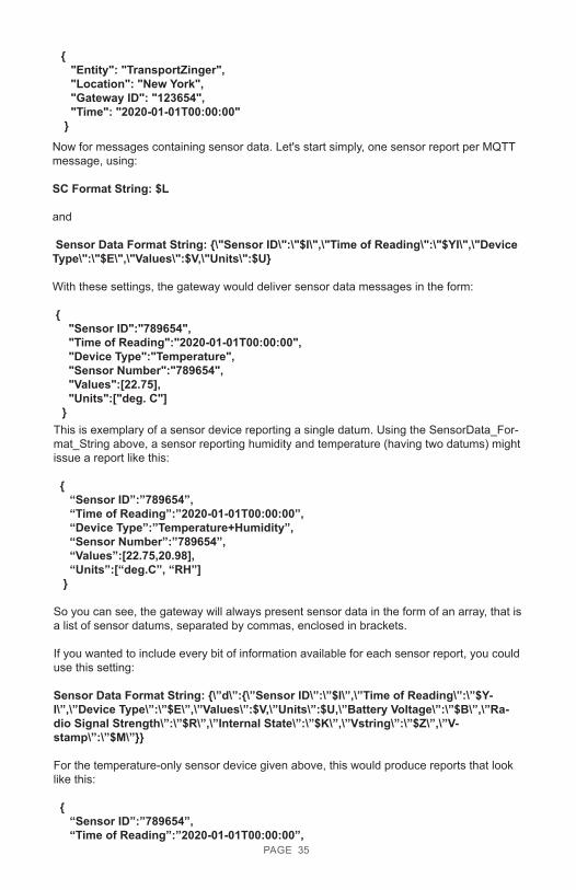
This is exemplary of a sensor device reporting a single datum. Using the SensorData_For-mat_String above, a sensor reporting humidity and temperature (having two datums) might issue a report like this:
{ “Sensor ID”:”789654”, “Time of Reading”:”2020-01-01T00:00:00”, “Device Type”:”Temperature+Humidity”, “Sensor Number”:”789654”, “Values”:[22.75,20.98], “Units”:[“deg.C”, “RH”] }
So you can see, the gateway will always present sensor data in the form of an array, that is a list of sensor datums, separated by commas, enclosed in brackets.
If you wanted to include every bit of information available for each sensor report, you could use this setting:
Sensor Data Format String: {\”d\”:{\”Sensor ID\”:\”$I\”,\”Time of Reading\”:\”$Y-I\”,\”Device Type\”:\”$E\”,\”Values\”:$V,\”Units\”:$U,\”Battery Voltage\”:\”$B\”,\”Ra-dio Signal Strength\”:\”$R\”,\”Internal State\”:\”$K\”,\”Vstring\”:\”$Z\”,\”V-stamp\”:\”$M\”}}
For the temperature-only sensor device given above, this would produce reports that look like this:
{ “Sensor ID”:”789654”, “Time of Reading”:”2020-01-01T00:00:00”,
Now for messages containing sensor data. Let's start simply, one sensor report per MQTT message, using:
SC Format String: $L
and Sensor Data Format String: {\"Sensor ID\":\"$I\",\"Time of Reading\":\"$YI\",\"Device Type\":\"$E\",\"Values\":$V,\"Units\":$U}
With these settings, the gateway would deliver sensor data messages in the form:
{ "Sensor ID":"789654", "Time of Reading":"2020-01-01T00:00:00", "Device Type":"Temperature", "Sensor Number":"789654", "Values":[22.75], "Units":["deg. C"] }
{ "Entity": "TransportZinger", "Location": "New York", "Gateway ID": "123654", "Time": "2020-01-01T00:00:00" }
PAGE 35
PAGE 36
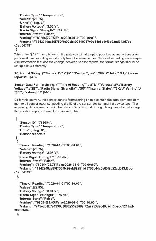
Where the “$AS” macro is found, the gateway will attempt to populate as many sensor re-ports as it can, including reports only from the same sensor. To avoid repeating sensor-spe-cific information that doesn’t change between sensor reports, the format strings should be set up a little differently:
SC Format String: {\”Sensor ID\”:\”$I\”,\”Device Type\”:\”$E\”,\”Units\”:$U,\”Sensor reports\”: $AS}
Sensor Data Format String: {\”Time of Reading\”:\”$YI\”,\”Values\”:$V,\”Battery Voltage\”:\”$B\”,\”Radio Signal Strength\”:\”$R\”,\”Internal State\”:\”$K\”,\”Vstring\”:\”$Z\”,\”Vstamp\”:\”$M\”}
So for this delivery, the sensor-centric format string should contain the data elements com-mon to all sensor reports, including the ID of the sensor device, and the device type. The remaining data elements go in the SensorData_Format_String. Using these format strings, the resulting reports should look similar to this:
{ “Sensor ID”:”789654”, “Device Type”:”Temperature”, “Units”:[“deg. C”], “Sensor reports”: [ { “Time of Reading”:”2020-01-01T00:00:00”, “Values”:[22.75], “Battery Voltage”:”3.05 V”,
“Device Type”:”Temperature”, “Values”:[22.75], “Units”:[“deg. C”] “Battery Voltage”:”3.05 V”, “Radio Signal Strength”:”-75 db”, “Internal State”:”False”, “Vstring”:”789654[22.75]False2020-01-01T00:00:00”, “Vstamp”:”1842246aa89f750f9c92eb89251b76700b44c5e60f9b22ad043d7bc-c3ad54719” }
“Radio Signal Strength”:”-75 db”, “Internal State”:”False”, “Vstring”: “789654[22.75]False2020-01-01T00:00:00”, “Vstamp”: “1842246aa89f750f9c92eb89251b76700b44c5e60f9b22ad043d7bc-c3ad54719” }, { “Time of Reading”:”2020-01-01T00:10:00”, “Values”:[22.85], “Battery Voltage”:”3.04 V”, “Radio Signal Strength”:”-76 db”, “Internal State”:”False”, “Vstring”:”789654[22.85]False2020-01-01T00:10:00 “, “Vstamp”:”745ed61b7e19908208025323689f72a7753dec4087d13b2dd1211ad-f98e09d62” },
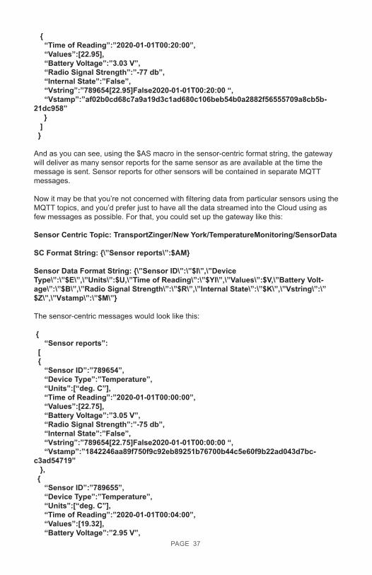
{ “Time of Reading”:”2020-01-01T00:20:00”, “Values”:[22.95], “Battery Voltage”:”3.03 V”, “Radio Signal Strength”:”-77 db”, “Internal State”:”False”, “Vstring”:”789654[22.95]False2020-01-01T00:20:00 “, “Vstamp”:”af02b0cd68c7a9a19d3c1ad680c106beb54b0a2882f56555709a8cb5b-21dc958” } ] }
And as you can see, using the $AS macro in the sensor-centric format string, the gateway will deliver as many sensor reports for the same sensor as are available at the time the message is sent. Sensor reports for other sensors will be contained in separate MQTT messages.
Now it may be that you’re not concerned with filtering data from particular sensors using the MQTT topics, and you’d prefer just to have all the data streamed into the Cloud using as few messages as possible. For that, you could set up the gateway like this:
Sensor Centric Topic: TransportZinger/New York/TemperatureMonitoring/SensorData
SC Format String: {\”Sensor reports\”:$AM}
Sensor Data Format String: {\”Sensor ID\”:\”$I\”,\”Device Type\”:\”$E\”,\”Units\”:$U,\”Time of Reading\”:\”$YI\”,\”Values\”:$V,\”Battery Volt-age\”:\”$B\”,\”Radio Signal Strength\”:\”$R\”,\”Internal State\”:\”$K\”,\”Vstring\”:\”$Z\”,\”Vstamp\”:\”$M\”}
The sensor-centric messages would look like this:
{ “Sensor reports”: [
PAGE 37
{ “Sensor ID”:”789654”, “Device Type”:”Temperature”, “Units”:[“deg. C”], “Time of Reading”:”2020-01-01T00:00:00”, “Values”:[22.75], “Battery Voltage”:”3.05 V”, “Radio Signal Strength”:”-75 db”, “Internal State”:”False”, “Vstring”:”789654[22.75]False2020-01-01T00:00:00 “, “Vstamp”:”1842246aa89f750f9c92eb89251b76700b44c5e60f9b22ad043d7bc-c3ad54719” }, { “Sensor ID”:”789655”, “Device Type”:”Temperature”, “Units”:[“deg. C”], “Time of Reading”:”2020-01-01T00:04:00”, “Values”:[19.32], “Battery Voltage”:”2.95 V”,
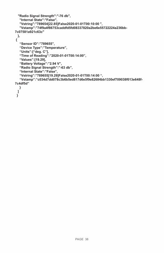
"Radio Signal Strength":"-76 db", "Internal State":"False", "Vstring":"789654[22.85]False2020-01-01T00:10:00 ", "Vstamp":"74f9a4f86753caddfd5fd08337820a2be6e55722224a236bb-7c07581a921c63c" }, { “Sensor ID”:”789655”, “Device Type”:”Temperature”, “Units”:[“deg. C”], “Time of Reading”:”2020-01-01T00:14:00”, “Values”:[19.29], “Battery Voltage”:”2.94 V”, “Radio Signal Strength”:”-63 db”, “Internal State”:”False”, “Vstring”:”789655[19.29]False2020-01-01T00:14:00 “, “Vstamp”:”c034d7dd078c3b6b5ed817d6e5f9e82684bb1330ef709038f013e648f-7c4df5d” } ] }
PAGE 38
SUPPORTFor technical support and troubleshooting tips please visit our support library online at monnit.com/support/. If you are unable to solve your issue using our online support, email Monnit support at [email protected] with your contact information and a description of the problem, and a support representative will call you within one business day.
For error reporting, please email a full description of the error to [email protected].
WARRANTY INFORMATION(a) Monnit warrants that Monnit-branded products (Products) will be free from defects in materials and workmanship for a period of one (1) year from the date of delivery with respect to hardware and will materially conform to their published specifications for a period of one (1) year with respect to software. Monnit may resell sensors manufactured by other entities and are subject to their individual warranties; Monnit will not enhance or extend those warranties. Monnit does not warrant that the software or any portion thereof is error free. Monnit will have no warranty obligation with respect to Products subjected to abuse, misuse, negligence or accident. If any software or firmware incorporated in any Product fails to conform to the warranty set forth in this Section, Monnit shall provide a bug fix or software patch correcting such non-conformance within a reasonable period after Monnit receives from customer (i) notice of such non-conformance, and (ii) sufficient information regarding such non-conformance so as to permit Monnit to create such bug fix or software patch. If any hardware component of any Product fails to conform to the warranty in this Section, Monnit shall, at its option, refund the purchase price less any discounts, or repair or replace non-conforming Products with conforming Products, or Products having substan-tially identical form, fit, and function and deliver the repaired or replacement Product to a carrier for land shipment to customer within a reasonable period after Monnit receives from customer (i) notice of such non-conformance, and (ii) the non-conforming Product provided; however, if, in its opinion, Monnit cannot repair or replace on commercially reasonable terms it may choose to refund the purchase price. Repair parts and replacement Products may be reconditioned or new. All replacement Products and parts become the property of Monnit. Repaired or replacement Products shall be subject to the warranty, if any remains, originally applicable to the Product repaired or replaced. Customer must obtain from Monnit a Return Material Authorization Number (RMA) prior to returning any Products to Monnit. Products returned under this Warranty must be unmodified.
Customer may return all Products for repair or replacement due to defects in original materials and workmanship if Monnit is notified within one year of customer’s receipt of the Product. Monnit reserves the right to repair or replace Products at its own and complete discretion. Customer must obtain from Monnit a Return Material Authorization Number (RMA) prior to returning any Products to Monnit. Products returned under this Warranty must be unmodified and in original packaging. Monnit reserves the right to refuse warran-ty repairs or replacements for any Products that are damaged or not in original form. For Products outside the one year warranty period repair services are available at Monnit at standard labor rates for a period of one year from the customer’s original date of receipt.
(b) As a condition to Monnit’s obligations under the immediately preceding paragraphs, cus-tomer shall return Products to be examined and replaced to Monnit’s facilities, in shipping cartons which clearly display a valid RMA number provided by Monnit. Customer acknowl-edges that replacement products may be repaired, refurbished or tested and found to be complying. Customer shall bear the risk of loss for such return shipment and shall bear all shipping costs. Monnit shall deliver replacements for Products determined by Monnit to be properly returned, shall bear the risk of loss and such costs of shipment of repaired Products or replacements, and shall credit customer’s reasonable costs of shipping such returned Products against future purchases.
PAGE 39

(c) Monnit’s sole obligation under the warranty described or set forth here shall be to repair or replace non-conforming products as set forth in the immediately preceding paragraph, or to refund the documented purchase price for non-conforming Products to customer. Mon-nit’s warranty obligations shall run solely to customer, and Monnit shall have no obligation to customers of customer or other users of the Products.
Limitation of Warranty and Remedies.
THE WARRANTY SET FORTH HEREIN IS THE ONLY WARRANTY APPLICABLE TO PRODUCTS PURCHASED BY CUSTOMER. ALL OTHER WARRANTIES, EXPRESS OR IMPLIED, INCLUDING BUT NOT LIMITED TO THE IMPLIED WARRANTIES OF MERCHANTABILITY AND FITNESS FOR A PARTICULAR PURPOSE ARE EXPRESSLY DISCLAIMED. MONNIT’S LIABILITY WHETHER IN CONTRACT, IN TORT, UNDER ANY WARRANTY, IN NEGLIGENCE OR OTHERWISE SHALL NOT EXCEED THE PURCHASE PRICE PAID BY CUSTOMER FOR THE PRODUCT. UNDER NO CIRCUMSTANCES SHALL MONNIT BE LIABLE FOR SPECIAL, INDIRECT OR CONSEQUENTIAL DAMAG-ES. THE PRICE STATED FOR THE PRODUCTS IS A CONSIDERATION IN LIMITING MONNIT’S LIABILITY. NO ACTION, REGARDLESS OF FORM, ARISING OUT OF THIS AGREEMENT MAY BE BROUGHT BY CUSTOMER MORE THAN ONE YEAR AFTER THE CAUSE OF ACTION HAS ACCRUED.
IN ADDITION TO THE WARRANTIES DISCLAIMED ABOVE, MONNIT SPECIFICALLY DISCLAIMS ANY AND ALL LIABILITY AND WARRANTIES, IMPLIED OR EXPRESSED, FOR USES REQUIRING FAIL-SAFE PERFORMANCE IN WHICH FAILURE OF A PROD-UCT COULD LEAD TO DEATH, SERIOUS PERSONAL INJURY, OR SEVERE PHYSICAL OR ENVIRONMENTAL DAMAGE SUCH AS, BUT NOT LIMITED TO, LIFE SUPPORT OR MEDICAL DEVICES OR NUCLEAR APPLICATIONS. PRODUCTS ARE NOT DESIGNED FOR AND SHOULD NOT BE USED IN ANY OF THESE APPLICATIONS.
PAGE 40
CERTIFICATIONS
United States FCC
This equipment has been tested and found to comply with the limits for a Class B digital device, pursuant to Part 15 of the FCC Rules. These limits are designed to provide reasonable protection against harmful interference in a residential installation. This equipment generates, uses, and can radiate radio frequency energy and, if not installed and used in accordance with the instruction manual, may cause harmful interference to radio communications. However, there is no guarantee that interference will not occur in a particular installation. If this equipment does cause harmful interference to radio or television reception, which can be determined by turning the equipment off and on, the user is encouraged to try to correct the interference by one of more of the following measures:
• Reorient or relocate the receiving antenna • Increase the separation between the equipment and receiver • Connect the equipment into an outlet on a circuit different from that to which the receiver is connected. • Consult the dealer or an experienced radio/TV technician for help.
Warning: Changes or modifications not expressly approved by Monnit could void the user’s authority to operate the equipment.
RF Exposure
FCC ID: ZTL-RFSC1This device has been designed to operate with an approved antenna listed below, and having a maximum gain of 5.1 dBi. Antennas not included in this list or having a gain greater than 5.1 dBi are strictly prohibited for use with this device. The required antenna impedance is 50 ohms.
To reduce potential radio interference to other users, the antenna type and its gain should be so chosen that the equivalent isotropically radiated power (EIRP) is not more than that required for successful communication.
Approved AntennasThe following antennas are approved for use with FCC ID: ZTL-RFSC1 • Hyperlink HG905RD-RSP (5.1 dBi Rubber Duck) • Pulse W1063 (3.0 dBi Rubber Duck) • ChangHong GSM-09 (2.0 dBi Rubber Duck) • Specialized Manufacturing MC-ANT-20/4.0C (4” whip)
WARNING: To satisfy FCC RF exposure requirements for mobile transmitting devices, the antenna used for this transmitter must not be co-located in conjunction with any antenna or transmitter.
PAGE 41

Canada (IC)
EnglishUnder Industry Canada regulations, this radio transmitter may only operate using an anten-na of a type and maximum (or lesser) gain approved for the transmitter by Industry Canada. To reduce potential radio interference to other users, the antenna type and its gain should be so chosen that the equivalent isotropically radiated power (e.i.r.p.) is not more than that necessary for successful communication.
This radio transmitter (IC: 9794A-RFSC1) has been approved by Industry Canada to op-erate with the antenna types listed below with the maximum permissible gain and required antenna impedance for each antenna type indicated. Antenna types not included in this list, having a gain greater than the maximum gain indicated for that type, are strictly prohibited for use with this device.
This device complies with Industry Canada license-exempt RSS standard(s). Operation is subject to the following two conditions: (1) this device may not cause interference, and (2) this device must accept any interference, including interference that may cause undesired operation of the device.
FrenchConformément à la réglementation d’Industrie Canada, le présent émetteur radio peut fonctionner avec une antenne d’un type et d’un gain maximal (ou inférieur) approuvé pour l’émetteur par Industrie Canada. Dans le but de réduire les risques de brouillage radioélec-trique à l’intention des autres utilisateurs, il faut choisir le type d’antenne et son gain de sorte que la puissance isotrope rayonnée équivalente (p.i.r.e.) ne dépasse pas l’intensité nécessaire à l’établissement d’une communication satisfaisante.
Le présent émetteur radio (IC: 9794A-RFSC1) a été approuvé par Industrie Canada pour fonctionner avec les types d’antenne énumérés ci-dessous et ayant un gain admissible maximal et l’impédance requise pour chaque type d’antenne. Les types d’antenne non inclus dans cette liste, ou dont le gain est supérieur au gain maximal indiqué, sont stricte-ment interdits pour l’exploitation de l’émetteur.
Le présent appareil est conforme aux CNR d’Industrie Canada applicables aux appareils radio exempts de licence. L’exploitation est autorisée aux deux conditions suivantes : (1) l’appareil ne doit pas produire de brouillage, et (2) l’utilisateur de l’appareil doit accepter tout brouillage radioélectrique subi, méme si le brouillage est susceptible d’en comprom-ettre le fonctionnement.
PAGE 42

For additional information on Monnit Wireless Sensors and Software, please visit us on the web at www.monnit.com.
Monnit Corporation3400 South West TempleSalt Lake City, UT 84115801-561-5555www.monnit.com
Monnit, Monnit Logo and all other trademarks are property of Monnit, Corp. © 2020 Monnit Corp. All Rights Reserved.
AUG-009 (02/20)