Embed Size (px)
Citation preview
Operation Manual
Flight Line Test Set Radio Altimeter
ALT-8000
EXPORT CONTROL WARNING: This document contains controlled technology or technical data under the jurisdiction of the Export Administration Regulations (EAR), 15 CFR 730-774. It cannot be transferred to any foreign third party without the specific prior approval of the U.S. Department of Commerce Bureau of Industry and Security BIS). Violations of these regulations are punishable by fine, imprisonment, or both.
Subject to Export Control, see Cover Page for details.
ALT-8000
Radio Alt imeter
Flight- l ine Test Set
Operation Manual
PUBLISHED BYAerof lex
COPYRIGHT © Aerof lex 2012
Al l r ights reserved. No part of th is publ icat ion may be reproduced, stored in a retr ieval system, or t ransmit ted in any form or by any means, elect ronic, mechanical , photocopying, recording or otherwise without the pr ior permission of the publ isher .
Original Issue Jun 2011
Issue 2 Oct 2011
Issue 3 Mar 2012
10200 West York / Wich i ta, Kansas 67215 U.S.A. / (316) 522-4981 / FAX (316) 524-2623

Subject to Export Control, see Cover Page for details.

ALT-8000OPERATION MANUAL
Subject to Export Control , see Cover Page for detai ls .i
ELECTROMAGNETIC COMPATIBILITY
Double shielded and proper ly terminated external interface cables must be used wi th this equipment when interfacing with the RS-232 and Ethernet.
For cont inued EMC compl iance, al l external cables must be shielded and 3 meters or less in length.
NOMENCLATURE STATEMENT
In this manual, ALT-8000, Simulator, Test Set or Uni t refers to the ALT-8000 Radio Al t imeter Fl ight Line Test Set .

ALT-8000OPERATION MANUAL
Subject to Export Control , see Cover Page for detai ls .i i
THIS PAGE INTENTIONALLY LEFT BLANK.

ALT-8000OPERATION MANUAL
Subject to Export Control , see Cover Page for detai ls .i i i
Declarat ion of Conformity
The Declarat ion of Conformity Cert i f icate included with the Unit should remain with the Unit .
Aerof lex recommends the operator reproduce a copy of the Declarat ion of Conformity Cert i f icate to be stored with the Operat ion Manual for future reference.

ALT-8000OPERATION MANUAL
Subject to Export Control , see Cover Page for detai ls .iv
THIS PAGE INTENTIONALLY LEFT BLANK.

ALT-8000OPERATION MANUAL
Subject to Export Control , see Cover Page for detai ls .v
Precautions
SAFETY FIRST - TO ALL OPERATIONS PERSONNEL
GENERAL CONDITIONS OF USE
This product is designed and tested to comply with the requirements of IEC/EN61010-1 ‘Safety requirements for electr ical equipment for measurement, control and laboratory use’ for Class I por table equipment and is for use in a po l lut ion degree 2 environment . The equipment is designed to operate from insta l lat ion supply Category I I .
Equipment should be protected f rom l iquids such as spi l ls, leaks, e tc. and precipi tat ion such as rain , snow, etc. When moving the equipment from a cold to hot environment, al low the temperature of the equipment to stabi l ize before the equipment is connected to the supply to avoid condensat ion forming.
The equipment must only be operated within the environmental condit ions speci f ied in the performance data.
CASE, COVER OR PANEL REMOVAL
Opening the Case Assembly exposes the operator to e lectr ical hazards that may resul t in elect r ical shock or equipment damage. Do not operate this Test Set with the Case Assembly open.
SAFETY IDENTIFICATION IN TECHNICAL MANUAL
This manual uses the fol lowing terms to draw attent ion to possible safety hazards that may exist when operat ing or servic ing this equipment:
SAFETY SYMBOLS IN MANUALS AND ON UNITS
IDENTIFIES CONDITIONS OR ACTIVITIES THAT, IF IGNORED, CAN RESULT IN EQUIPMENT OR PROPERTY DAMAGE, E.G. , FIRE.
IDENTIFIES CONDITIONS OR ACTIVITIES THAT, IF IGNORED, CAN RESULT IN PERSONAL INJURY OR DEATH.
CAUTION : Refer to accompanying documents. (This symbol refers to speci f ic CAUTIONS represented on the uni t and clar i f ied in the text .)
Indicates a Toxic hazard.
Indicates i tem is stat ic sensi t ive.
AC TERMINAL: Terminal that may supply or be suppl ied with AC or al ternat ing vol tage.
CAUTION
WARNINGWARNING
ALT-8000OPERATION MANUAL
Subject to Export Control , see Cover Page for detai ls .vi
SAFETY FIRST - TO ALL OPERATIONS PERSONNEL (cont)
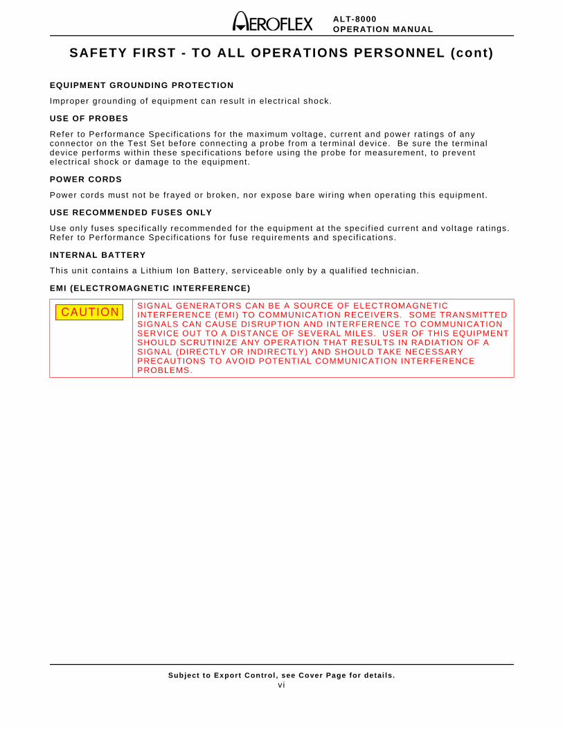
EQUIPMENT GROUNDING PROTECTION
Improper grounding of equipment can resul t in electr ical shock.
USE OF PROBES
Refer to Per formance Specif icat ions for the maximum voltage, current and power ra t ings of any connector on the Test Set before connect ing a probe f rom a terminal device. Be sure the terminal device performs with in these speci f icat ions before using the probe for measurement, to prevent electr ical shock or damage to the equipment .
POWER CORDS
Power cords must not be frayed or broken, nor expose bare wir ing when operat ing this equipment.
USE RECOMMENDED FUSES ONLY
Use only fuses speci f ical ly recommended for the equipment a t the speci f ied current and vol tage rat ings. Refer to Per formance Specif icat ions for fuse requirements and speci f icat ions.
INTERNAL BATTERY
This uni t contains a Li thium Ion Battery, serviceable only by a qual i f ied technician.
EMI (ELECTROMAGNETIC INTERFERENCE)
SIGNAL GENERATORS CAN BE A SOURCE OF ELECTROMAGNETIC INTERFERENCE (EMI) TO COMMUNICATION RECEIVERS. SOME TRANSMITTED SIGNALS CAN CAUSE DISRUPTION AND INTERFERENCE TO COMMUNICATION SERVICE OUT TO A DISTANCE OF SEVERAL MILES. USER OF THIS EQUIPMENT SHOULD SCRUTINIZE ANY OPERATION THAT RESULTS IN RADIATION OF A SIGNAL (DIRECTLY OR INDIRECTLY) AND SHOULD TAKE NECESSARY PRECAUTIONS TO AVOID POTENTIAL COMMUNICATION INTERFERENCE PROBLEMS.
CAUTION
ALT-8000OPERATION MANUAL
Subject to Export Control , see Cover Page for detai ls .vi i
SAFETY FIRST - TO ALL OPERATIONS PERSONNEL (cont)
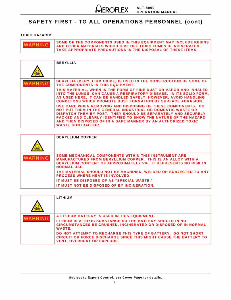
TOXIC HAZARDS
SOME OF THE COMPONENTS USED IN THIS EQUIPMENT MAY INCLUDE RESINS AND OTHER MATERIALS WHICH GIVE OFF TOXIC FUMES IF INCINERATED. TAKE APPROPRIATE PRECAUTIONS IN THE DISPOSAL OF THESE ITEMS.
BERYLLIA
BERYLLIA (BERYLLIUM OXIDE) IS USED IN THE CONSTRUCTION OF SOME OF THE COMPONENTS IN THIS EQUIPMENT. THIS MATERIAL, WHEN IN THE FORM OF FINE DUST OR VAPOR AND INHALED INTO THE LUNGS, CAN CAUSE A RESPIRATORY DISEASE. IN ITS SOLID FORM, AS USED HERE, IT CAN BE HANDLED SAFELY, HOWEVER, AVOID HANDLING CONDITIONS WHICH PROMOTE DUST FORMATION BY SURFACE ABRASION.USE CARE WHEN REMOVING AND DISPOSING OF THESE COMPONENTS. DO NOT PUT THEM IN THE GENERAL INDUSTRIAL OR DOMESTIC WASTE OR DISPATCH THEM BY POST. THEY SHOULD BE SEPARATELY AND SECURELY PACKED AND CLEARLY IDENTIFIED TO SHOW THE NATURE OF THE HAZARD AND THEN DISPOSED OF IN A SAFE MANNER BY AN AUTHORIZED TOXIC WASTE CONTRACTOR.
BERYLLIUM COPPER
SOME MECHANICAL COMPONENTS WITHIN THIS INSTRUMENT ARE MANUFACTURED FROM BERYLLIUM COPPER. THIS IS AN ALLOY WITH A BERYLLIUM CONTENT OF APPROXIMATELY 5%. IT REPRESENTS NO RISK IN NORMAL USE.THE MATERIAL SHOULD NOT BE MACHINED, WELDED OR SUBJECTED TO ANY PROCESS WHERE HEAT IS INVOLVED.IT MUST BE DISPOSED OF AS “SPECIAL WASTE.”IT MUST NOT BE DISPOSED OF BY INCINERATION.
LITHIUM
A LITHIUM BATTERY IS USED IN THIS EQUIPMENT.LITHIUM IS A TOXIC SUBSTANCE SO THE BATTERY SHOULD IN NO CIRCUMSTANCES BE CRUSHED, INCINERATED OR DISPOSED OF IN NORMAL WASTE. DO NOT ATTEMPT TO RECHARGE THIS TYPE OF BATTERY. DO NOT SHORT CIRCUIT OR FORCE DISCHARGE SINCE THIS MIGHT CAUSE THE BATTERY TO VENT, OVERHEAT OR EXPLODE.
WARNING
WARNING
WARNING
WARNING
ALT-8000OPERATION MANUAL
Subject to Export Control , see Cover Page for detai ls .vi i i
SAFETY FIRST - TO ALL OPERATIONS PERSONNEL (cont)
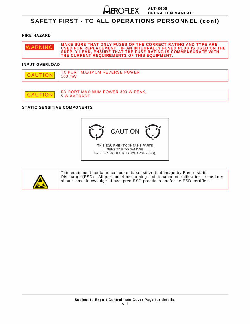
FIRE HAZARD
INPUT OVERLOAD
STATIC SENSITIVE COMPONENTS
MAKE SURE THAT ONLY FUSES OF THE CORRECT RATING AND TYPE ARE USED FOR REPLACEMENT. IF AN INTEGRALLY FUSED PLUG IS USED ON THE SUPPLY LEAD, ENSURE THAT THE FUSE RATING IS COMMENSURATE WITH THE CURRENT REQUIREMENTS OF THIS EQUIPMENT.
TX PORT MAXIMUM REVERSE POWER 100 mW
RX PORT MAXIMUM POWER 300 W PEAK, 5 W AVERAGE
This equipment contains components sensi t ive to damage by Electrostat ic Discharge (ESD). A l l personnel per forming maintenance or cal ibrat ion procedures should have knowledge of accepted ESD pract ices and/or be ESD cert i f ied.
WARNING
CAUTION
CAUTION
THIS EQUIPMENT CONTAINS PARTSSENSITIVE TO DAMAGE
BY ELECTROSTATIC DISCHARGE (ESD).
CAUTION
ALT-8000OPERATION MANUAL
Subject to Export Control , see Cover Page for detai ls .ix
RoHS Product Information for People’s Republic of China
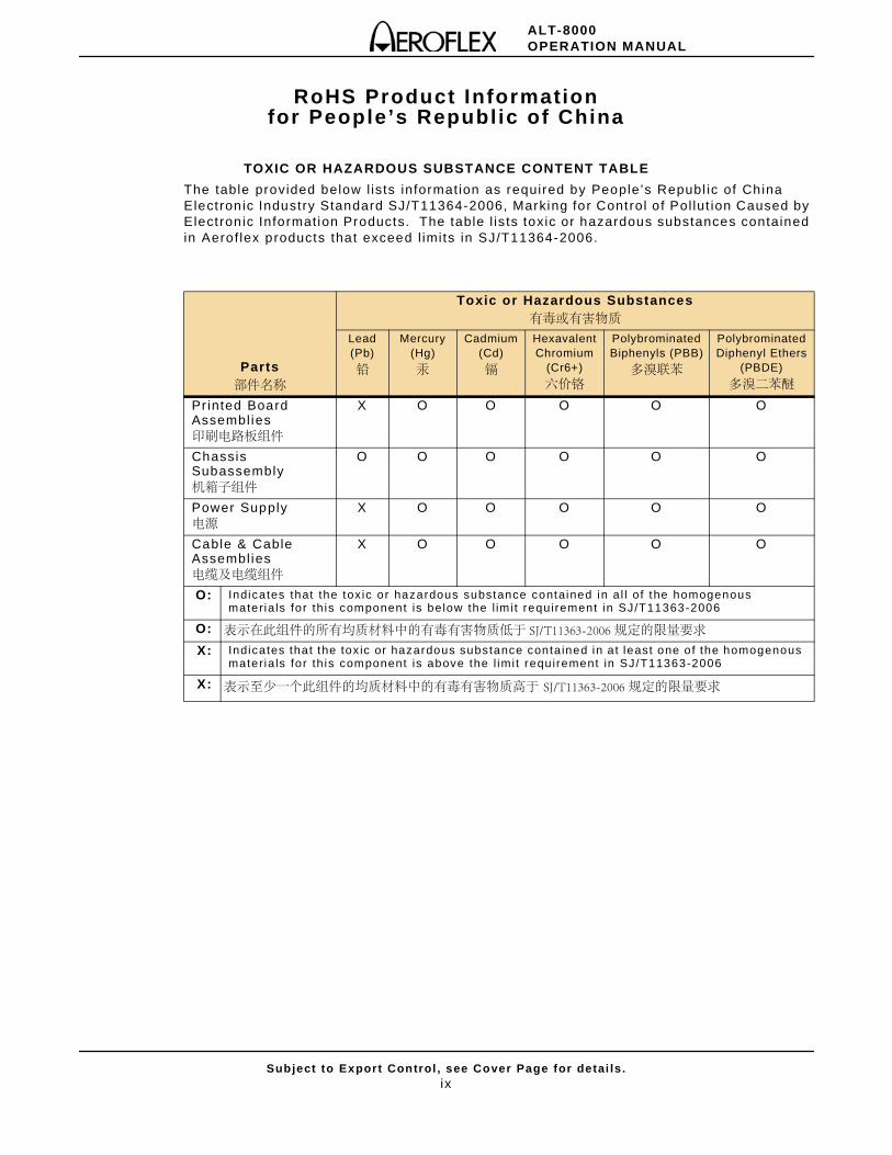
TOXIC OR HAZARDOUS SUBSTANCE CONTENT TABLE
The table provided below l ists information as required by People’s Republ ic of China Elect ron ic Industry Standard SJ/T11364-2006, Marking for Control o f Pol lut ion Caused by Elect ron ic Information Products. The table l is ts toxic or hazardous substances contained in Aerof lex products that exceed l imits in SJ/T11364-2006.
Parts部件名称
Toxic or Hazardous Substances有毒或有害物质
Lead (Pb)
铅
Mercury (Hg)
汞
Cadmium (Cd)
镉
Hexavalent Chromium
(Cr6+)
六价铬
Polybrominated Biphenyls (PBB)
多溴联苯
Polybrominated Diphenyl Ethers
(PBDE)
多溴二苯醚
Printed Board Assembl ies印刷电路板组件
X O O O O O
Chassis Subassembly机箱子组件
O O O O O O
Power Supply电源
X O O O O O
Cable & Cable Assembl ies电缆及电缆组件
X O O O O O
O: Indicates that the tox ic or hazardous substance contained in a l l o f the homogenous materia ls for th is component is be low the l im it requi rement in SJ/T11363-2006
O: 表示在此组件的所有均质材料中的有毒有害物质低于 SJ/T11363-2006 规定的限量要求
X: Indicates that the tox ic or hazardous substance conta ined in at least one of the homogenous materia ls for th is component is above the l imi t requirement in SJ/T11363-2006
X: 表示至少一个此组件的均质材料中的有毒有害物质高于 SJ/T11363-2006 规定的限量要求

ALT-8000OPERATION MANUAL
Subject to Export Control , see Cover Page for detai ls .x
THIS PAGE INTENTIONALLY LEFT BLANK.
Chapter Heading
Subject to Export Control , see Cover Page for detai ls .xi
Preface
SCOPE
This Manual contains instruct ions for operat ing the ALT-8000. The Operator should become thoroughly famil iar wi th this manual before at tempting to operate the equipment.
ORGANIZATION
This manual is composed of the fol lowing chapters:
CHAPTER 1 - DESCRIPTION
Provides an int roduct ion and a br ie f overview of Test Set funct ions and features.
CHAPTER 2 - TEST SET OPERATION
Ident i f ies Test Set Controls, Connectors and Indicators.
Provides Power On and Power Of f procedures.
Provides funct ional descr ipt ion of Graphic User Inter face (GUI) components.
Provides instruct ions for def ining Test Set parameters.
CHAPTER 3 - TEST SET FUNCTIONS
Provides funct ional descr ipt ion of Test Set funct ions.
CHAPTER 4 - TESTING
Provides ALT-8000 test guidel ines.
CHAPTER 5 - MAINTENANCE
Ident i f ies Operator Level Troubleshoot ing and Maintenance procedures.
CHAPTER 6 - PRINCIPLES OF OPERATION
Provides information regarding Test Set pr inciples of operat ion.
CHAPTER 7 - SPECIFICATIONS
Ident i f ies Test Set speci f icat ions.
APPENDIX A - PIN-OUT TABLES
Ident i f ies connector pin locat ions.
APPENDIX B - TERMINOLOGY
Lists terms and abbreviat ions used in this manual.

Chapter Heading
Subject to Export Control , see Cover Page for detai ls .xi i
THIS PAGE INTENTIONALLY LEFT BLANK.
ALT-8000OPERATION MANUAL
Subject to Export Control , see Cover Page for detai ls .xi i i
Service Upon Receipt of Material
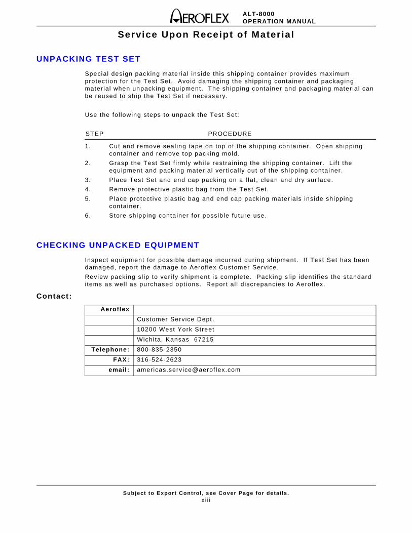
UNPACKING TEST SET
Special design packing mater ial inside this shipping conta iner provides maximum protect ion for the Test Set. Avoid damaging the shipping container and packaging mater ial when unpacking equipment. The shipping container and packaging mater ial can be reused to sh ip the Test Set i f necessary.
Use the fol lowing steps to unpack the Test Set:
STEP PROCEDURE
1. Cut and remove seal ing tape on top of the shipping container. Open shipping conta iner and remove top packing mold.
2. Grasp the Test Set f i rmly whi le restraining the shipping container . L i f t the equipment and packing mater ial vert ical ly out of the shipping container .
3. Place Test Set and end cap packing on a f lat , c lean and dry sur face.
4. Remove protect ive plast ic bag from the Test Set .
5. Place protect ive plast ic bag and end cap packing mater ials inside shipping conta iner.
6. Store shipping conta iner for possible future use.
CHECKING UNPACKED EQUIPMENT
Inspect equipment for possible damage incurred dur ing shipment. I f Test Set has been damaged, report the damage to Aerof lex Customer Service.
Review packing sl ip to ver i fy shipment is complete. Packing sl ip ident i f ies the standard i tems as wel l as purchased opt ions. Report al l d iscrepancies to Aerof lex.
Contact:
Aeroflex
Customer Service Dept .
10200 West York Street
Wichi ta, Kansas 67215
Telephone: 800-835-2350
FAX: 316-524-2623
email : amer icas.service@aerof lex.com
ALT-8000OPERATION MANUAL
Subject to Export Control , see Cover Page for detai ls .xiv
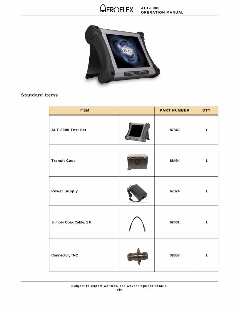
Standard Items
ITEM PART NUMBER QTY
ALT-8000 Test Set 87340 1
Transit Case 88494 1
Power Supply 67374 1
Jumper Coax Cable, 1 ft 62401 1
Connector, TNC 38353 1
ALT-8000OPERATION MANUAL
Subject to Export Control , see Cover Page for detai ls .xv
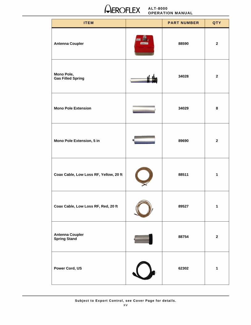
Antenna Coupler 88590 2
Mono Pole, Gas Filled Spring 34028 2
Mono Pole Extension 34029 8
Mono Pole Extension, 5 in 89690 2
Coax Cable, Low Loss RF, Yellow, 20 ft 88511 1
Coax Cable, Low Loss RF, Red, 20 ft 89527 1
Antenna Coupler Spring Stand 88754 2
Power Cord, US 62302 1
ITEM PART NUMBER QTY
ALT-8000OPERATION MANUAL
Subject to Export Control , see Cover Page for detai ls .xvi
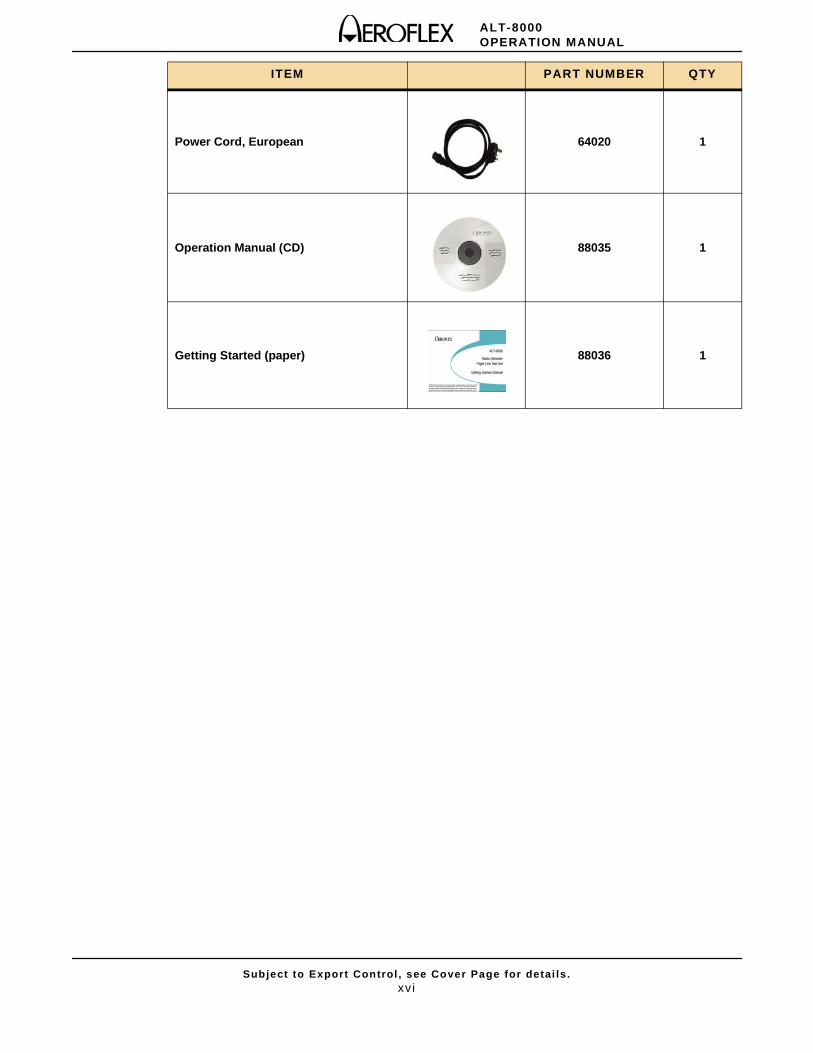
Power Cord, European 64020 1
Operation Manual (CD) 88035 1
Getting Started (paper) 88036 1
ITEM PART NUMBER QTY
ALT-8000OPERATION MANUAL
Subject to Export Control , see Cover Page for detai ls .xvi i
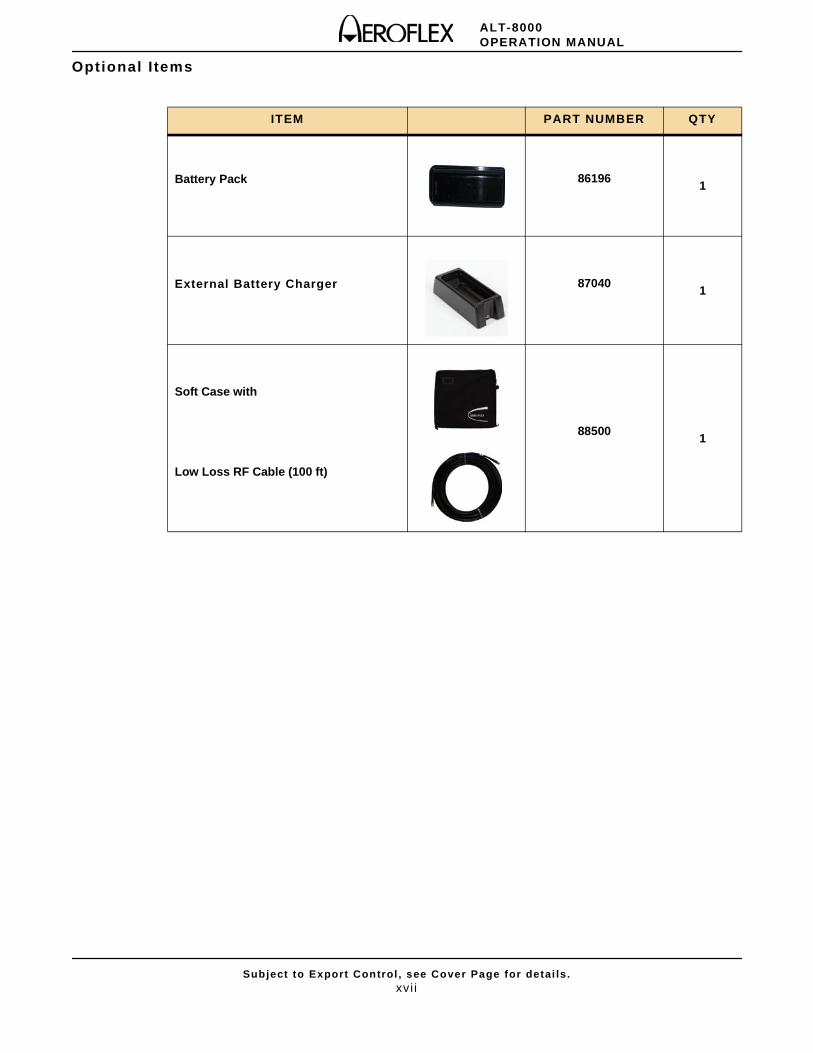
Optional I tems
ITEM PART NUMBER QTY
Battery Pack 861961
External Battery Charger 870401
Soft Case with
Low Loss RF Cable (100 ft)
885001

ALT-8000OPERATION MANUAL
Subject to Export Control , see Cover Page for detai ls .xvi i i
THIS PAGE INTENTIONALLY LEFT BLANK.
ALT-8000OPERATION MANUAL
Subject to Export Control , see Cover Page for detai ls .1
Table of Contents
Chapter 1 - Description . . . . . . . . . . . . . . . . . . . . . . . . . 1 - 1
Int roduct ion ALT-8000 . . . . . . . . . . . . . . . . . . . . . . . . . . . . . . . . . . . . . . . . . . . . . . 1 - 1
Scope . . . . . . . . . . . . . . . . . . . . . . . . . . . . . . . . . . . . . . . . . . . . . . . . . . . . . . . 1 - 1
Nomenclature Cross-Reference List . . . . . . . . . . . . . . . . . . . . . . . . . . . . . . . . . . 1 - 1
Equipment Capabi l i t ies and Features . . . . . . . . . . . . . . . . . . . . . . . . . . . . . . . . . . . . 1 - 1
Capabi l i t ies . . . . . . . . . . . . . . . . . . . . . . . . . . . . . . . . . . . . . . . . . . . . . . . . . . . 1 - 2
Features . . . . . . . . . . . . . . . . . . . . . . . . . . . . . . . . . . . . . . . . . . . . . . . . . . . . . 1 - 2
Ut i l i t ies . . . . . . . . . . . . . . . . . . . . . . . . . . . . . . . . . . . . . . . . . . . . . . . . . . . . . . 1 - 2
Chapter 2 - Test Set Operation . . . . . . . . . . . . . . . . . . . 2 - 1
Int roduct ion . . . . . . . . . . . . . . . . . . . . . . . . . . . . . . . . . . . . . . . . . . . . . . . . . . . . . 2 - 1Power Requirements . . . . . . . . . . . . . . . . . . . . . . . . . . . . . . . . . . . . . . . . . . . . . . . 2 - 1
Power . . . . . . . . . . . . . . . . . . . . . . . . . . . . . . . . . . . . . . . . . . . . . . . . . . . . . . 2 - 1
Bat tery Recharging Using External Power Supply . . . . . . . . . . . . . . . . . . . . . . . . 2 - 2
Battery Recharging Using Battery Charger . . . . . . . . . . . . . . . . . . . . . . . . . . . . . 2 - 2
Instal lat ion . . . . . . . . . . . . . . . . . . . . . . . . . . . . . . . . . . . . . . . . . . . . . . . . . . . . . . 2 - 3
Venti lat ion Requirements . . . . . . . . . . . . . . . . . . . . . . . . . . . . . . . . . . . . . . . . . 2 - 3
Bench Top Instal lat ion . . . . . . . . . . . . . . . . . . . . . . . . . . . . . . . . . . . . . . . . . . . 2 - 3
Contro ls and Connectors . . . . . . . . . . . . . . . . . . . . . . . . . . . . . . . . . . . . . . . . . . . . 2 - 4
Front Panel Controls . . . . . . . . . . . . . . . . . . . . . . . . . . . . . . . . . . . . . . . . . . . . . 2 - 4
Rear Panel Connectors . . . . . . . . . . . . . . . . . . . . . . . . . . . . . . . . . . . . . . . . . . . 2 - 6
Operat ing Procedures . . . . . . . . . . . . . . . . . . . . . . . . . . . . . . . . . . . . . . . . . . . . . . 2 - 7
Power ON Test Set . . . . . . . . . . . . . . . . . . . . . . . . . . . . . . . . . . . . . . . . . . . . . . 2 - 7
Power OFF Test Set . . . . . . . . . . . . . . . . . . . . . . . . . . . . . . . . . . . . . . . . . . . . . 2 - 7
User Inter face Components . . . . . . . . . . . . . . . . . . . . . . . . . . . . . . . . . . . . . . . . . . . 2 - 8
Launch Bar . . . . . . . . . . . . . . . . . . . . . . . . . . . . . . . . . . . . . . . . . . . . . . . . . . . 2 - 8
Funct ion Keys . . . . . . . . . . . . . . . . . . . . . . . . . . . . . . . . . . . . . . . . . . . . . . . . . 2 - 9
Simulat ion Funct ion Windows . . . . . . . . . . . . . . . . . . . . . . . . . . . . . . . . . . . . . 2 - 10
Funct ion Window Icons . . . . . . . . . . . . . . . . . . . . . . . . . . . . . . . . . . . . . . . . . . 2 - 11
Def ining Parameters . . . . . . . . . . . . . . . . . . . . . . . . . . . . . . . . . . . . . . . . . . . . . . 2 - 12
Enter ing Numeric Values . . . . . . . . . . . . . . . . . . . . . . . . . . . . . . . . . . . . . . . . . 2 - 12
Numeric Keypad and Sl ider Bar . . . . . . . . . . . . . . . . . . . . . . . . . . . . . . . . . . . . 2 - 12
Data Slew Bar . . . . . . . . . . . . . . . . . . . . . . . . . . . . . . . . . . . . . . . . . . . . . . . . 2 - 13
Rotary Knob . . . . . . . . . . . . . . . . . . . . . . . . . . . . . . . . . . . . . . . . . . . . . . . . . . 2 - 13
Drop-down Menus . . . . . . . . . . . . . . . . . . . . . . . . . . . . . . . . . . . . . . . . . . . . . . 2 - 13
Selectable Units . . . . . . . . . . . . . . . . . . . . . . . . . . . . . . . . . . . . . . . . . . . . . . . 2 - 14
Locked Fields . . . . . . . . . . . . . . . . . . . . . . . . . . . . . . . . . . . . . . . . . . . . . . . . 2 - 14
ALT-8000OPERATION MANUAL
Subject to Export Control , see Cover Page for detai ls .2
Chapter 3 - Test Set Functions . . . . . . . . . . . . . . . . . . . 3 - 1
Int roduct ion . . . . . . . . . . . . . . . . . . . . . . . . . . . . . . . . . . . . . . . . . . . . . . . . . . . . . . 3 - 1Test Set Funct ions . . . . . . . . . . . . . . . . . . . . . . . . . . . . . . . . . . . . . . . . . . . . . . . . . 3 - 1
Simulat ion Funct ion Window . . . . . . . . . . . . . . . . . . . . . . . . . . . . . . . . . . . . . . . 3 - 1
Prof i le Setup Funct ion Window . . . . . . . . . . . . . . . . . . . . . . . . . . . . . . . . . . . . . . 3 - 4
Prof i le Management . . . . . . . . . . . . . . . . . . . . . . . . . . . . . . . . . . . . . . . . . . . . . 3 - 7
Test Setup . . . . . . . . . . . . . . . . . . . . . . . . . . . . . . . . . . . . . . . . . . . . . . . . . . . . . 3 - 10
Test Setup Funct ion Window . . . . . . . . . . . . . . . . . . . . . . . . . . . . . . . . . . . . . . 3 - 10
Set t ings Storage . . . . . . . . . . . . . . . . . . . . . . . . . . . . . . . . . . . . . . . . . . . . . . . 3 - 13
Status Bar Alert Messages . . . . . . . . . . . . . . . . . . . . . . . . . . . . . . . . . . . . . . . 3 - 15
Chapter 4 - Test ing . . . . . . . . . . . . . . . . . . . . . . . . . . . . 4 - 1
Int roduct ion . . . . . . . . . . . . . . . . . . . . . . . . . . . . . . . . . . . . . . . . . . . . . . . . . . . . . . 4 - 1
Ident i fy ing Instal led Software Version . . . . . . . . . . . . . . . . . . . . . . . . . . . . . . . . 4 - 1
Antenna Couplers and Instal lat ion Ki t . . . . . . . . . . . . . . . . . . . . . . . . . . . . . . . . 4 - 2
Antenna Coupler Instal lat ion and Connect ion . . . . . . . . . . . . . . . . . . . . . . . . . . . 4 - 4
Feeder Connect ion . . . . . . . . . . . . . . . . . . . . . . . . . . . . . . . . . . . . . . . . . . . . . 4 - 5
Setup . . . . . . . . . . . . . . . . . . . . . . . . . . . . . . . . . . . . . . . . . . . . . . . . . . . . . . 4 - 6
Chapter 5 - Maintenance . . . . . . . . . . . . . . . . . . . . . . . . 5 - 1
Int roduct ion . . . . . . . . . . . . . . . . . . . . . . . . . . . . . . . . . . . . . . . . . . . . . . . . . . . . . . 5 - 1
Visual Inspect ions . . . . . . . . . . . . . . . . . . . . . . . . . . . . . . . . . . . . . . . . . . . . . . 5 - 1
External Cleaning . . . . . . . . . . . . . . . . . . . . . . . . . . . . . . . . . . . . . . . . . . . . . . . 5 - 1
Maintenance Procedures . . . . . . . . . . . . . . . . . . . . . . . . . . . . . . . . . . . . . . . . . . . . 5 - 1
Bat tery Replacement . . . . . . . . . . . . . . . . . . . . . . . . . . . . . . . . . . . . . . . . . . . . 5 - 1
ALT-8000 Software Update . . . . . . . . . . . . . . . . . . . . . . . . . . . . . . . . . . . . . . . . 5 - 2
System Configurat ion Funct ion Window . . . . . . . . . . . . . . . . . . . . . . . . . . . . . . . 5 - 3
Chapter 6 - Principles of Operat ion . . . . . . . . . . . . . . . . 6 - 1
Principles of Operat ion . . . . . . . . . . . . . . . . . . . . . . . . . . . . . . . . . . . . . . . . . . . . . . 6 - 1
ALT-8000 Test Operat ion . . . . . . . . . . . . . . . . . . . . . . . . . . . . . . . . . . . . . . . . . 6 - 1
Assemblies . . . . . . . . . . . . . . . . . . . . . . . . . . . . . . . . . . . . . . . . . . . . . . . . . . . 6 - 1
Interconnect Block Diagram . . . . . . . . . . . . . . . . . . . . . . . . . . . . . . . . . . . . . . . . 6 - 2
Radio Al t imeters . . . . . . . . . . . . . . . . . . . . . . . . . . . . . . . . . . . . . . . . . . . . . . . . 6 - 2
FM/CW Radio Alt imeter . . . . . . . . . . . . . . . . . . . . . . . . . . . . . . . . . . . . . . . . . . . 6 - 3
Pulse Radio Al t imeter Systems . . . . . . . . . . . . . . . . . . . . . . . . . . . . . . . . . . . . 6 - 10
Systems Coupled With Radio Al t imeter . . . . . . . . . . . . . . . . . . . . . . . . . . . . . . . 6 - 12
ALT-8000OPERATION MANUAL
Subject to Export Control , see Cover Page for detai ls .3
Chapter 7 - Product Specif ications . . . . . . . . . . . . . . . . 7 - 1
User Inter face . . . . . . . . . . . . . . . . . . . . . . . . . . . . . . . . . . . . . . . . . . . . . . . . . . . . 7 - 1Generator . . . . . . . . . . . . . . . . . . . . . . . . . . . . . . . . . . . . . . . . . . . . . . . . . . . . . . . 7 - 1Receiver . . . . . . . . . . . . . . . . . . . . . . . . . . . . . . . . . . . . . . . . . . . . . . . . . . . . . . . . 7 - 2
Master Osci l lator . . . . . . . . . . . . . . . . . . . . . . . . . . . . . . . . . . . . . . . . . . . . . . . . . . 7 - 3Coupler . . . . . . . . . . . . . . . . . . . . . . . . . . . . . . . . . . . . . . . . . . . . . . . . . . . . . . . . 7 - 3Battery . . . . . . . . . . . . . . . . . . . . . . . . . . . . . . . . . . . . . . . . . . . . . . . . . . . . . . . . . 7 - 3
Physical Character ist ics . . . . . . . . . . . . . . . . . . . . . . . . . . . . . . . . . . . . . . . . . . . . . 7 - 3Environmental . . . . . . . . . . . . . . . . . . . . . . . . . . . . . . . . . . . . . . . . . . . . . . . . . . . . 7 - 4Accessor ies . . . . . . . . . . . . . . . . . . . . . . . . . . . . . . . . . . . . . . . . . . . . . . . . . . . . . 7 - 5
Appendix A - Pin-Out Tables . . . . . . . . . . . . . . . . . . . . .A - 1
Appendix B - Terminology . . . . . . . . . . . . . . . . . . . . . . .B - 1
ALT-8000OPERATION MANUAL
Subject to Export Control , see Cover Page for detai ls .1
List of Figures
Aerof lex ALT-8000 . . . . . . . . . . . . . . . . . . . . . . . . . . . . . . . . . . . . . . . . . . . . . . . . . 1 - 1
AC Adaptor . . . . . . . . . . . . . . . . . . . . . . . . . . . . . . . . . . . . . . . . . . . . . . . . . . . . . . 2 - 1
Bat tery Charger . . . . . . . . . . . . . . . . . . . . . . . . . . . . . . . . . . . . . . . . . . . . . . . . . . . 2 - 2
ALT-8000 Screen Cover/Stand . . . . . . . . . . . . . . . . . . . . . . . . . . . . . . . . . . . . . . . . 2 - 3
Front Panel Contro ls . . . . . . . . . . . . . . . . . . . . . . . . . . . . . . . . . . . . . . . . . . . . . . . 2 - 4
Test Set Rear Panel Controls and Connectors . . . . . . . . . . . . . . . . . . . . . . . . . . . . . 2 - 6
Power Up Screen . . . . . . . . . . . . . . . . . . . . . . . . . . . . . . . . . . . . . . . . . . . . . . . . . . 2 - 7
Launch Bar - Open/Close Tab . . . . . . . . . . . . . . . . . . . . . . . . . . . . . . . . . . . . . . . . . 2 - 8
Launch Bar Appears In Front of Funct ion Window . . . . . . . . . . . . . . . . . . . . . . . . . . . 2 - 8
Launch Bar Funct ion Keys . . . . . . . . . . . . . . . . . . . . . . . . . . . . . . . . . . . . . . . . . . . 2 - 9
Simulat ion Funct ion Window . . . . . . . . . . . . . . . . . . . . . . . . . . . . . . . . . . . . . . . . . 2 - 10
Numeric Keypad . . . . . . . . . . . . . . . . . . . . . . . . . . . . . . . . . . . . . . . . . . . . . . . . . 2 - 12
Data Slew Bar . . . . . . . . . . . . . . . . . . . . . . . . . . . . . . . . . . . . . . . . . . . . . . . . . . . 2 - 13
Rotary Knob . . . . . . . . . . . . . . . . . . . . . . . . . . . . . . . . . . . . . . . . . . . . . . . . . . . . 2 - 13
Drop-down Menu . . . . . . . . . . . . . . . . . . . . . . . . . . . . . . . . . . . . . . . . . . . . . . . . . 2 - 13
Selectable Units . . . . . . . . . . . . . . . . . . . . . . . . . . . . . . . . . . . . . . . . . . . . . . . . . 2 - 14
Locked Field . . . . . . . . . . . . . . . . . . . . . . . . . . . . . . . . . . . . . . . . . . . . . . . . . . . . 2 - 14
Simulat ion Funct ion Window (Simulat ion: Manual) . . . . . . . . . . . . . . . . . . . . . . . . . . . 3 - 1
Simulat ion Funct ion Window (Simulat ion: Prof i le) . . . . . . . . . . . . . . . . . . . . . . . . . . . 3 - 2
Radio Al t imeter Test Funct ion Window Pulse . . . . . . . . . . . . . . . . . . . . . . . . . . . . . . 3 - 3
Prof i le Setup Funct ion Window . . . . . . . . . . . . . . . . . . . . . . . . . . . . . . . . . . . . . . . . 3 - 4
Edi t Leg # Window . . . . . . . . . . . . . . . . . . . . . . . . . . . . . . . . . . . . . . . . . . . . . . . . . 3 - 6
Manage Prof i les Window (Store Prof i le) . . . . . . . . . . . . . . . . . . . . . . . . . . . . . . . . . . 3 - 7
Manage Prof i les Window (Store Name Entry) . . . . . . . . . . . . . . . . . . . . . . . . . . . . . . 3 - 7
Manage Prof i les Window (Delete Prof i le) . . . . . . . . . . . . . . . . . . . . . . . . . . . . . . . . . 3 - 8
Load Prof i le Window . . . . . . . . . . . . . . . . . . . . . . . . . . . . . . . . . . . . . . . . . . . . . . . 3 - 9
Test Setup Funct ion Window RF Port Direct . . . . . . . . . . . . . . . . . . . . . . . . . . . . . . . . . . . . . . . . . . . . . . . . . . . 3 - 10
Test Setup Funct ion Window RF Port Coupler . . . . . . . . . . . . . . . . . . . . . . . . . . . . . . . . . . . . . . . . . . . . . . . . . . 3 - 10
Manage Set t ings Window (Store Sett ings) . . . . . . . . . . . . . . . . . . . . . . . . . . . . . . . 3 - 13
Manage Set t ings Window (Store Name Entry) . . . . . . . . . . . . . . . . . . . . . . . . . . . . . 3 - 13
Manage Set t ings Window (Delete Sett ings) . . . . . . . . . . . . . . . . . . . . . . . . . . . . . . . 3 - 14
Load Set t ings Window . . . . . . . . . . . . . . . . . . . . . . . . . . . . . . . . . . . . . . . . . . . . . 3 - 15
Status Bar . . . . . . . . . . . . . . . . . . . . . . . . . . . . . . . . . . . . . . . . . . . . . . . . . . . . . 3 - 15
Alert Message Log . . . . . . . . . . . . . . . . . . . . . . . . . . . . . . . . . . . . . . . . . . . . . . . . 3 - 16
ALT-8000 Antenna Coupler . . . . . . . . . . . . . . . . . . . . . . . . . . . . . . . . . . . . . . . . . . . 4 - 2
ALT-8000OPERATION MANUAL
Subject to Export Control , see Cover Page for detai ls .2
Gas Loaded Shock . . . . . . . . . . . . . . . . . . . . . . . . . . . . . . . . . . . . . . . . . . . . . . . . . 4 - 3
Sect ional Extension Poles . . . . . . . . . . . . . . . . . . . . . . . . . . . . . . . . . . . . . . . . . . . . 4 - 3
Spr ing Loaded Shock . . . . . . . . . . . . . . . . . . . . . . . . . . . . . . . . . . . . . . . . . . . . . . . 4 - 3
Low Loss RF Coax Cable . . . . . . . . . . . . . . . . . . . . . . . . . . . . . . . . . . . . . . . . . . . . 4 - 3
Jumper RF Coax Cable . . . . . . . . . . . . . . . . . . . . . . . . . . . . . . . . . . . . . . . . . . . . . . 4 - 3
ALT-8000 RF Connect ions . . . . . . . . . . . . . . . . . . . . . . . . . . . . . . . . . . . . . . . . . . . 4 - 4
ALT-8000 RF Connect ions (Feeders) . . . . . . . . . . . . . . . . . . . . . . . . . . . . . . . . . . . . 4 - 5
ALT-8000 Antenna Coupler Instal led . . . . . . . . . . . . . . . . . . . . . . . . . . . . . . . . . . . . 4 - 6
Delay Cal ibrat ion Screen . . . . . . . . . . . . . . . . . . . . . . . . . . . . . . . . . . . . . . . . . . . . 4 - 7
Alt i tude Indicator Zero Screen . . . . . . . . . . . . . . . . . . . . . . . . . . . . . . . . . . . . . . . . . 4 - 8
Alt i tude Pause Key . . . . . . . . . . . . . . . . . . . . . . . . . . . . . . . . . . . . . . . . . . . . . . . . . 4 - 9
Paused Alt i tude Rate / Manual Al t i tude Slew . . . . . . . . . . . . . . . . . . . . . . . . . . . . . . 4 - 10
Mult i - leg Prof i le Example . . . . . . . . . . . . . . . . . . . . . . . . . . . . . . . . . . . . . . . . . . . 4 - 12
UUT Parameters(part of the Simulat ion Funct ion Window) . . . . . . . . . . . . . . . . . . . . . . . . . . . . . . . . 4 - 15
Bat tery Replacement . . . . . . . . . . . . . . . . . . . . . . . . . . . . . . . . . . . . . . . . . . . . . . . 5 - 2
USB Ports . . . . . . . . . . . . . . . . . . . . . . . . . . . . . . . . . . . . . . . . . . . . . . . . . . . . . . . 5 - 3
System Configurat ion - Status . . . . . . . . . . . . . . . . . . . . . . . . . . . . . . . . . . . . . . . . . 5 - 4
System Configurat ion - Hardware . . . . . . . . . . . . . . . . . . . . . . . . . . . . . . . . . . . . . . 5 - 5
System Configurat ion – UI Options . . . . . . . . . . . . . . . . . . . . . . . . . . . . . . . . . . . . . 5 - 6
System Configurat ion – Network . . . . . . . . . . . . . . . . . . . . . . . . . . . . . . . . . . . . . . . 5 - 7
System Configurat ion – Date/Time . . . . . . . . . . . . . . . . . . . . . . . . . . . . . . . . . . . . . 5 - 8
System Info . . . . . . . . . . . . . . . . . . . . . . . . . . . . . . . . . . . . . . . . . . . . . . . . . . . . . . 5 - 9
Diagnost ics . . . . . . . . . . . . . . . . . . . . . . . . . . . . . . . . . . . . . . . . . . . . . . . . . . . . . 5 - 10
Assembly Interconnect Block Diagram . . . . . . . . . . . . . . . . . . . . . . . . . . . . . . . . . . . 6 - 2
Typical FM/CWLRRA System Components . . . . . . . . . . . . . . . . . . . . . . . . . . . . . . . . 6 - 3
Simpl i f ied FM/CW Radio Alt imeter . . . . . . . . . . . . . . . . . . . . . . . . . . . . . . . . . . . . . . 6 - 4
Convent ional FM/CW Sweep . . . . . . . . . . . . . . . . . . . . . . . . . . . . . . . . . . . . . . . . . . 6 - 5
Convent ional FM/CW Radio Al t imeter Block Diagram . . . . . . . . . . . . . . . . . . . . . . . . . 6 - 5
CDF FM/CW Radio Alt imeter Block Diagram . . . . . . . . . . . . . . . . . . . . . . . . . . . . . . . 6 - 6
CDF FM/CW Sweep . . . . . . . . . . . . . . . . . . . . . . . . . . . . . . . . . . . . . . . . . . . . . . . . 6 - 7
Triple LRRA Antenna Instal la t ion . . . . . . . . . . . . . . . . . . . . . . . . . . . . . . . . . . . . . . . 6 - 7
LRRA Antenna Insta l lat ion . . . . . . . . . . . . . . . . . . . . . . . . . . . . . . . . . . . . . . . . . . . 6 - 8
Radio Al t imeter Antenna Height at Touchdown . . . . . . . . . . . . . . . . . . . . . . . . . . . . . 6 - 8
Typical EFIS . . . . . . . . . . . . . . . . . . . . . . . . . . . . . . . . . . . . . . . . . . . . . . . . . . . . . 6 - 9
Analog Indicator Dial Type . . . . . . . . . . . . . . . . . . . . . . . . . . . . . . . . . . . . . . . . . . 6 - 10
Analog Indicator Moving Tape Type . . . . . . . . . . . . . . . . . . . . . . . . . . . . . . . . . . . . 6 - 10
AN/APN-209 Pulse Radio Al t imeter . . . . . . . . . . . . . . . . . . . . . . . . . . . . . . . . . . . . 6 - 11
Pulse Radio Al t imeter Block Diagram . . . . . . . . . . . . . . . . . . . . . . . . . . . . . . . . . . . 6 - 12
Approach Types . . . . . . . . . . . . . . . . . . . . . . . . . . . . . . . . . . . . . . . . . . . . . . . . . . 6 - 13
Terrain Awareness and Warning System . . . . . . . . . . . . . . . . . . . . . . . . . . . . . . . . . 6 - 13
GPWS Inputs . . . . . . . . . . . . . . . . . . . . . . . . . . . . . . . . . . . . . . . . . . . . . . . . . . . . 6 - 14
ALT-8000OPERATION MANUAL
Subject to Export Control , see Cover Page for detai ls .1
List of Tables
Funct ion Window Icons . . . . . . . . . . . . . . . . . . . . . . . . . . . . . . . . . . . . . . . . . . . . . 2 - 11
Numeric Keypad Icons . . . . . . . . . . . . . . . . . . . . . . . . . . . . . . . . . . . . . . . . . . . . . 2 - 12
Ethernet Pin-Out Diagram . . . . . . . . . . . . . . . . . . . . . . . . . . . . . . . . . . . . . . . . . . . A - 1
USB Host 1 Pin-Out Diagram . . . . . . . . . . . . . . . . . . . . . . . . . . . . . . . . . . . . . . . . . A - 1
USB Host 2 Pin-Out Diagram . . . . . . . . . . . . . . . . . . . . . . . . . . . . . . . . . . . . . . . . A - 2
USB OTG Pin-Out Diagram . . . . . . . . . . . . . . . . . . . . . . . . . . . . . . . . . . . . . . . . . . A - 2
DC Power Connector Pin-Out Diagram . . . . . . . . . . . . . . . . . . . . . . . . . . . . . . . . . . A - 2
ALT-8000OPERATION MANUAL
Subject to Export Control , see Cover Page for detai ls .1 - 1
Chapter 1 - Descript ion
1.1 INTRODUCTION ALT-8000
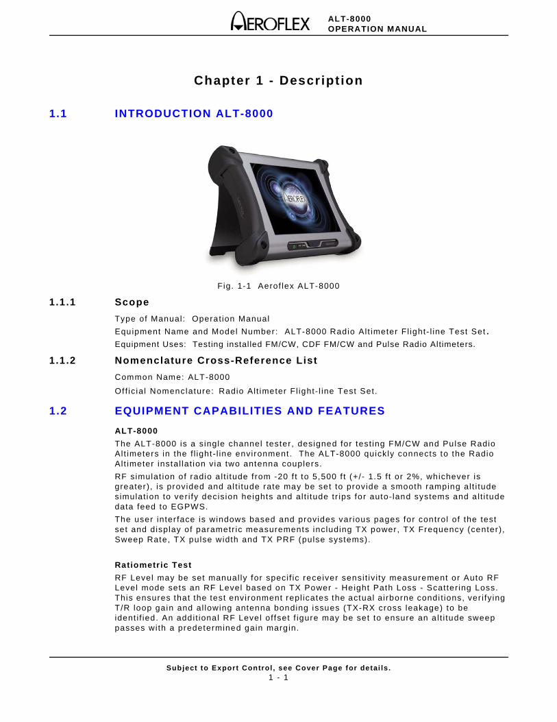
Fig. 1-1 Aerof lex ALT-8000
1.1.1 Scope
Type of Manual: Operat ion Manual
Equipment Name and Model Number: ALT-8000 Radio Alt imeter Fl ight- l ine Test Set .
Equipment Uses: Testing installed FM/CW, CDF FM/CW and Pulse Radio Altimeters.
1.1.2 Nomenclature Cross-Reference List
Common Name: ALT-8000
Of f ic ial Nomenclature: Radio Alt imeter Fl ight- l ine Test Set.
1.2 EQUIPMENT CAPABILITIES AND FEATURES
ALT-8000
The ALT-8000 is a single channel tester, designed for test ing FM/CW and Pulse Radio Alt imeters in the f l ight - l ine environment . The ALT-8000 quickly connects to the Radio Alt imeter instal lat ion via two antenna couplers.
RF simulat ion of radio a l t i tude f rom -20 f t to 5,500 f t (+/- 1.5 f t or 2%, whichever is greater), is provided and al t i tude rate may be set to provide a smooth ramping al t i tude simulat ion to ver i fy decision heights and al t i tude tr ips for auto- land systems and a l t i tude data feed to EGPWS.
The user inter face is windows based and provides var ious pages for control of the test set and display of parametr ic measurements including TX power, TX Frequency (center), Sweep Rate, TX pulse width and TX PRF (pulse systems).
Ratiometric Test
RF Level may be set manual ly for speci f ic receiver sensi t iv i ty measurement or Auto RF Level mode sets an RF Level based on TX Power - Height Path Loss - Scatter ing Loss. This ensures that the test environment repl icates the actual airborne condi t ions, ver i fy ing T/R loop gain and al lowing antenna bonding issues (TX-RX cross leakage) to be ident i f ied. An addit ional RF Level of fset f igure may be set to ensure an a l t i tude sweep passes with a predetermined gain marg in.
ALT-8000OPERATION MANUAL
Subject to Export Control , see Cover Page for detai ls .1 - 2
Transit Case
The ALT-8000 is shipped in a rugged transi t case which provides storage for the accessories; AC-DC Power Supply/Charger, External Battery Charger , Antenna Couplers, Coupler Poles, RF Coax Cables, Power Cords, Operat ion Manual CD and Gett ing Star ted Manual.
1.2.1 Capabil it ies
The ALT-8000 provides users with the fol lowing standard capabi l i t ies:
• Test FMCW Radio Alt imeters, including CDF Types
• Test Pulse Radio Al t imeters (non pulse compression types)
• Direct connect to UUT T/R or to instal led system via Antenna Couplers
1.2.2 Features
• Ratio-metr ic RF loop test al lows TX, RX, Antenna or Feeder faul ts ( to be ident i f ied).
• Programmable mult i - leg Cl imb/Descend prof i les
• Large touch screen 12 in d isplay, wi th simple user interface
• Remote Control Inter face LAN
• Lightweight and compact , <10 lbs. (4.5 kg)
• Bat tery 4 hours plus durat ion
• Changeable bat tery
• Radio Al t imeter Test Funct ional Window
1.2.3 Utilities
• Software Upgrade
• Operat ional Status
• Setup
ALT-8000OPERATION MANUAL
Subject to Export Control , see Cover Page for detai ls .2 - 1
Chapter 2 - Test Set Operation
2.1 INTRODUCTION
This chapter refers to loca l operat ion of an ALT-8000 conf igured with factory default sett ings, un less otherwise speci f ied. New Test Sets are conf igured to start in the factory defaul t sett ing. Review Instal lat ion and Power Requirements before using the Test Set.
2.2 POWER REQUIREMENTS
2.2.1 Power
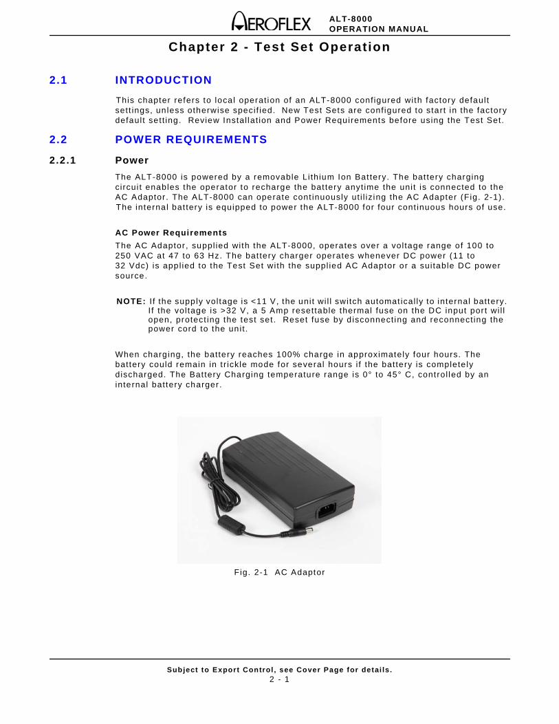
The ALT-8000 is powered by a removable Li thium Ion Bat tery. The bat tery charging circui t enables the operator to recharge the bat tery anyt ime the uni t is connected to the AC Adaptor . The ALT-8000 can operate cont inuously ut i l iz ing the AC Adapter (Fig . 2-1). The interna l bat tery is equipped to power the ALT-8000 for four cont inuous hours of use.
AC Power Requirements
The AC Adaptor , suppl ied with the ALT-8000, operates over a vol tage range of 100 to 250 VAC at 47 to 63 Hz. The bat tery charger operates whenever DC power (11 to 32 Vdc) is appl ied to the Test Set with the suppl ied AC Adaptor or a sui table DC power source.
NOTE: I f the supply vol tage is <11 V, the uni t wi l l switch automat ical ly to internal battery. I f the vol tage is >32 V, a 5 Amp resettable thermal fuse on the DC input por t wi l l open, protect ing the test set . Reset fuse by d isconnect ing and reconnect ing the power cord to the un it .
When charg ing, the battery reaches 100% charge in approximately four hours. The battery could remain in t r ickle mode for several hours i f the battery is complete ly discharged. The Bat tery Charging temperature range is 0° to 45° C, control led by an internal battery charger .
Fig. 2-1 AC Adaptor
ALT-8000OPERATION MANUAL
Subject to Export Control , see Cover Page for detai ls .2 - 2
2.2.2 Battery Recharging Using External Power Supply
Perform the fol lowing steps to recharge the battery using an external power supply:
STEP PROCEDURE
1. Connect AC Line Cable to AC POWER Connector on the AC Adaptor and an appropriate AC power source.
2. Connect the AC Adaptor DC output to the DC POWER Connector on the ALT-8000.
3. Ver i fy the BATTERY indicator displays b l inking green.
4. Al low four hours for battery charge or unt i l the BATTERY Indicator displays a steady green. Refer to 2.4.1 for addit ional bat tery indicators.
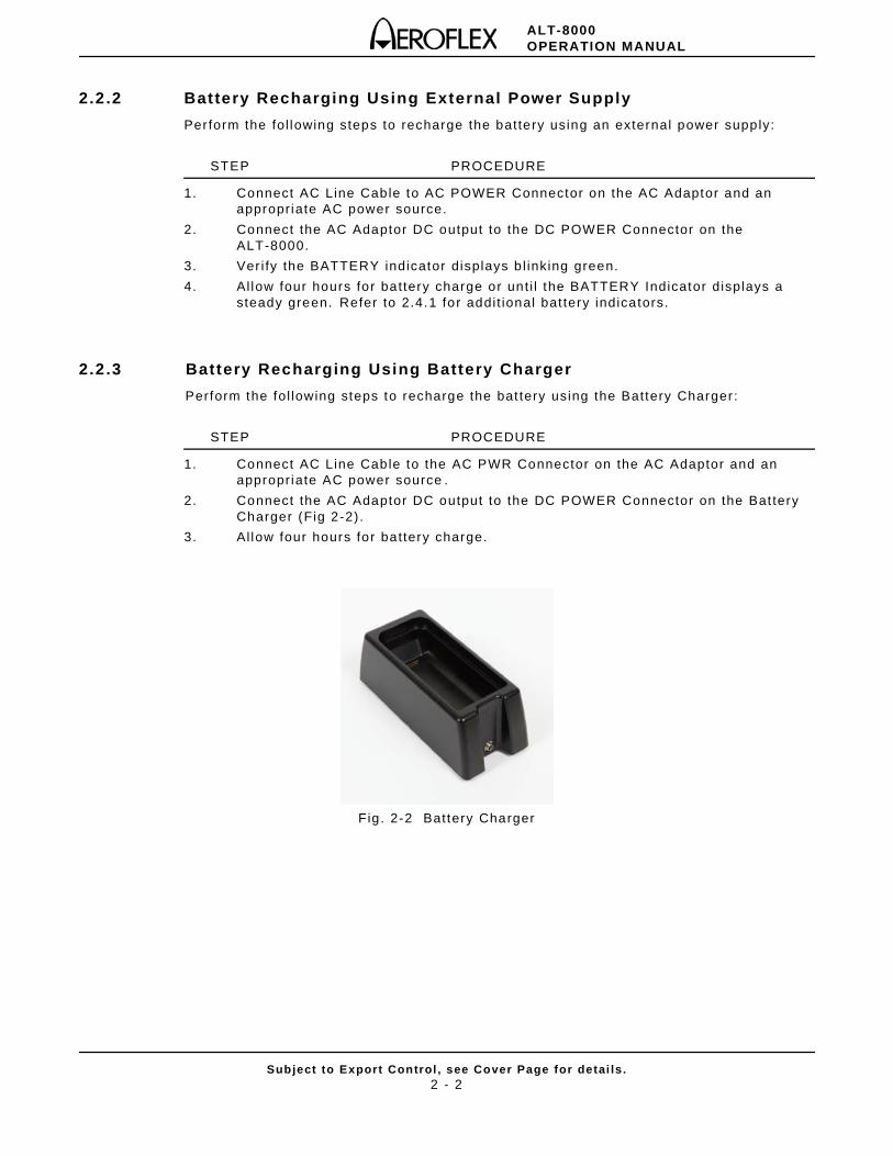
2.2.3 Battery Recharging Using Battery Charger
Perform the fol lowing steps to recharge the bat tery using the Battery Charger :
STEP PROCEDURE
1. Connect AC Line Cable to the AC PWR Connector on the AC Adaptor and an appropriate AC power source .
2. Connect the AC Adaptor DC output to the DC POWER Connector on the Bat tery Charger (Fig 2-2) .
3. Al low four hours for battery charge.
Fig. 2-2 Battery Charger
ALT-8000OPERATION MANUAL
Subject to Export Control , see Cover Page for detai ls .2 - 3
2.3 INSTALLATION
2.3.1 Ventilat ion Requirements
The ALT-8000 is convect ion cooled by the enclosure case. Avoid standing the Test Set on or c lose to other equipment that is hot.
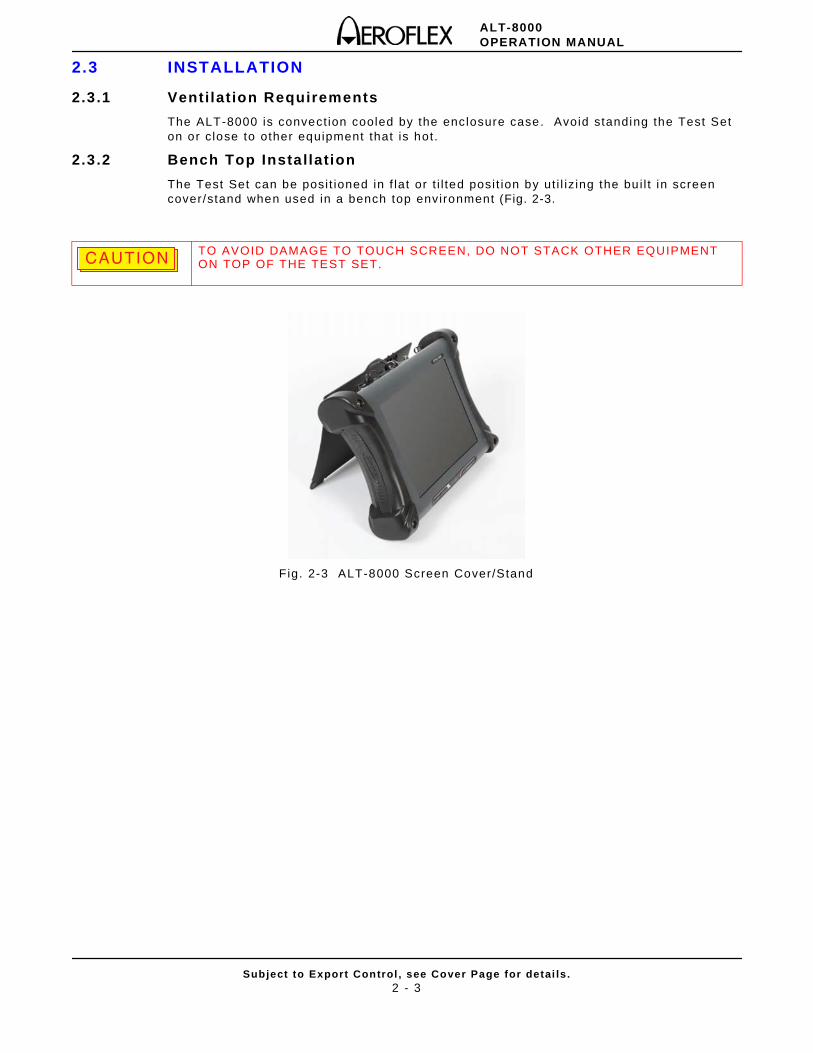
2.3.2 Bench Top Installation
The Test Set can be posi t ioned in f lat or t i l ted posi t ion by ut i l iz ing the bu i l t in screen cover/stand when used in a bench top environment (Fig. 2-3.
Fig. 2-3 ALT-8000 Screen Cover/Stand
TO AVOID DAMAGE TO TOUCH SCREEN, DO NOT STACK OTHER EQUIPMENT ON TOP OF THE TEST SET.CAUTIONCAUTION
ALT-8000OPERATION MANUAL
Subject to Export Control , see Cover Page for detai ls .2 - 4
2.4 CONTROLS AND CONNECTORS
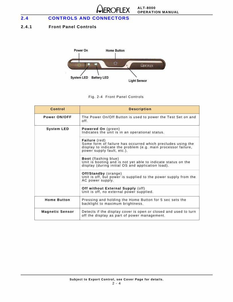
2.4.1 Front Panel Controls
Fig. 2-4 Front Panel Controls
Control Description
Power ON/OFF The Power On/Off Button is used to power the Test Set on and off .
System LED Powered On (green) Indicates the uni t is in an operat ional sta tus.
Failure ( red)Some form of fai lure has occurred which precludes using the display to indicate the problem (e.g. main processor fai lure, power supply faul t , etc. ) .
Boot ( f lash ing blue) Unit is boot ing and is not yet able to indicate status on the display (dur ing ini t ia l OS and appl icat ion load).
Off/Standby (orange) Unit is o f f , but power is suppl ied to the power supply from the AC power supply.
Off without External Supply (of f )Unit is of f , no external power suppl ied.
Home Button Pressing and hold ing the Home Button for 5 sec sets the backl ight to maximum br ightness.
Magnetic Sensor Detects i f the display cover is open or c losed and used to turn off the display as par t of power management.
ALT-8000OPERATION MANUAL
Subject to Export Control , see Cover Page for detai ls .2 - 5
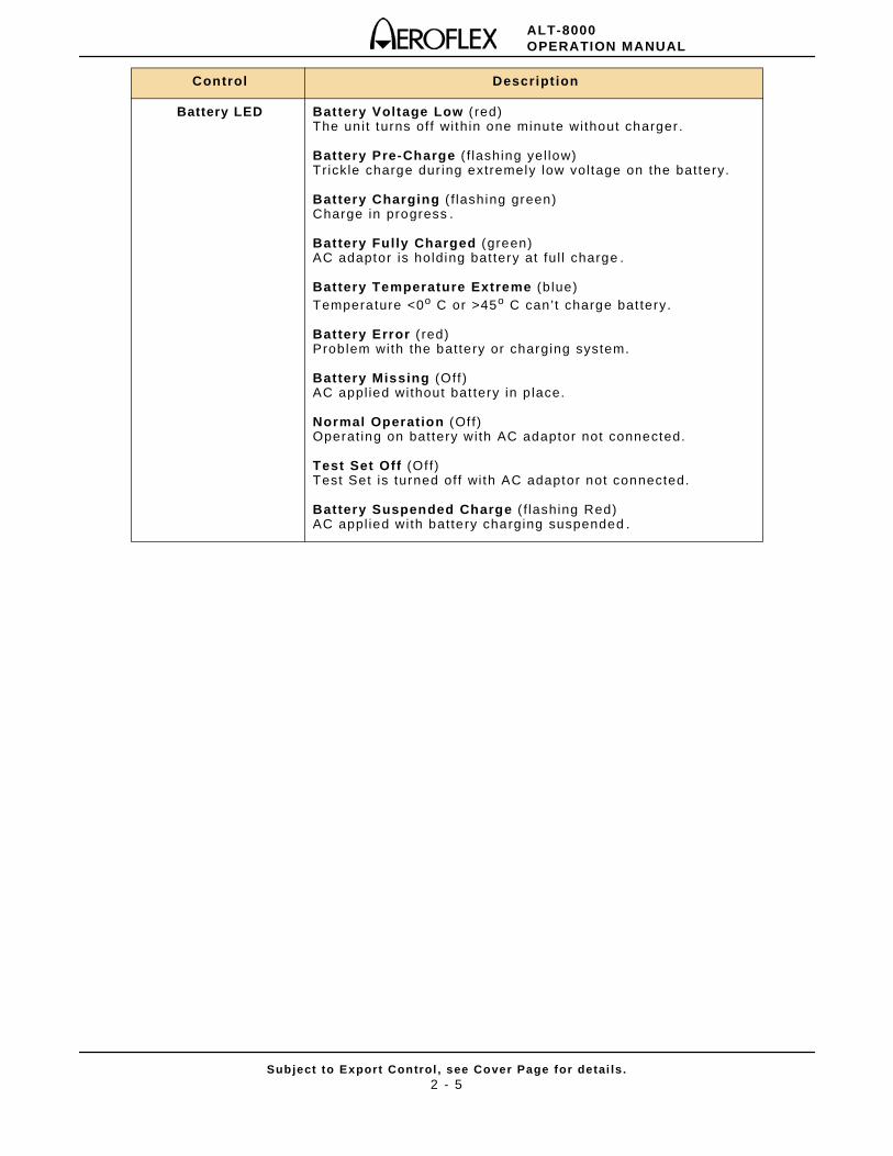
Control Descript ion
Battery LED Battery Voltage Low ( red)The unit turns off wi thin one minute without charger .
Battery Pre-Charge ( f lashing yel low)Trickle charge dur ing extremely low vol tage on the battery.
Battery Charging ( f lashing green)Charge in progress .
Battery Fully Charged (green)AC adaptor is holding bat tery at ful l charge .
Battery Temperature Extreme (b lue)Temperature <0o C or >45o C can’t charge bat tery.
Battery Error ( red)Problem with the battery or charging system.
Battery Missing (Off )AC appl ied without bat tery in p lace.
Normal Operation (Of f)Operat ing on battery with AC adaptor not connected.
Test Set Off (Of f)Test Set is turned off wi th AC adaptor not connected.
Battery Suspended Charge ( f lashing Red)AC appl ied with battery charging suspended .
ALT-8000OPERATION MANUAL
Subject to Export Control , see Cover Page for detai ls .2 - 6
2.4.2 Rear Panel Connectors
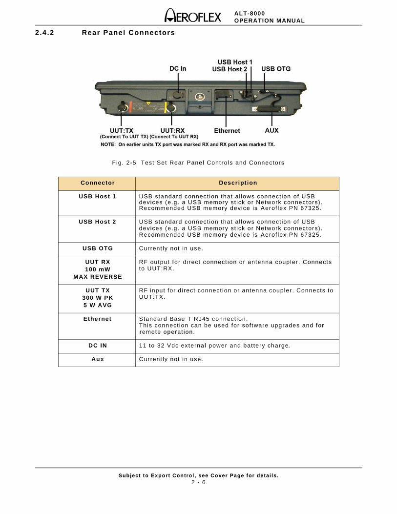
Fig. 2-5 Test Set Rear Panel Controls and Connectors
Connector Descript ion
USB Host 1 USB standard connect ion that al lows connect ion of USB devices (e.g. a USB memory st ick or Network connectors) . Recommended USB memory device is Aerof lex PN 67325.
USB Host 2 USB standard connect ion that al lows connect ion of USB devices (e.g. a USB memory st ick or Network connectors) . Recommended USB memory device is Aerof lex PN 67325.
USB OTG Current ly not in use.
UUT RX100 mW
MAX REVERSE
RF output for di rect connect ion or antenna coupler . Connects to UUT:RX.
UUT TX300 W PK5 W AVG
RF input for d irect connect ion or antenna coupler . Connects to UUT:TX.
Ethernet Standard Base T RJ45 connect ion. This connect ion can be used for software upgrades and for remote operat ion.
DC IN 11 to 32 Vdc external power and battery charge.
Aux Current ly not in use.
ALT-8000OPERATION MANUAL
Subject to Export Control , see Cover Page for detai ls .2 - 7
2.5 OPERATING PROCEDURES
2.5.1 Power ON Test Set
After complet ing Ini t ia l Instal lat ion, per form the fol lowing steps to Turn On the Test Set:
STEP PROCEDURE
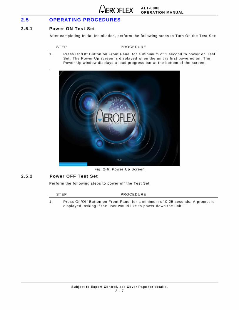
1. Press On/Off Button on Front Panel for a minimum of 1 second to power on Test Set . The Power Up screen is displayed when the unit is f i rst powered on. The Power Up window displays a load progress bar at the bottom of the screen.
.
Fig. 2-6 Power Up Screen
2.5.2 Power OFF Test Set
Perform the fol lowing steps to power off the Test Set:
STEP PROCEDURE
1. Press On/Off Button on Front Panel for a minimum of 0 .25 seconds. A prompt is displayed, asking i f the user would l ike to power down the uni t .
ALT-8000OPERATION MANUAL
Subject to Export Control , see Cover Page for detai ls .2 - 8
2.6 USER INTERFACE COMPONENTS
The Test Set User Interface (UI) is a touch screen control panel that provides a f lexib le working environment for users. The UI u t i l izes maximized Funct ion Windows i .e. one funct ion window occupies the whole screen area. The UI is navigated local ly using the Front Panel Touch Screen.
2.6.1 Launch Bar
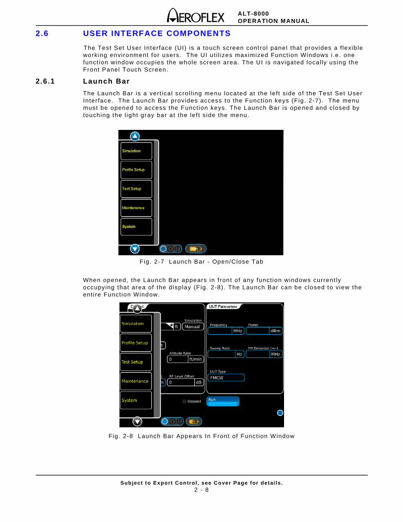
The Launch Bar is a vert ical scrol l ing menu located at the lef t s ide of the Test Set User Interface. The Launch Bar provides access to the Funct ion keys (Fig. 2-7). The menu must be opened to access the Funct ion keys. The Launch Bar is opened and closed by touching the l ight gray bar a t the lef t s ide the menu.
Fig. 2-7 Launch Bar - Open/Close Tab
When opened, the Launch Bar appears in front of any funct ion windows current ly occupying that area of the display (F ig. 2-8) . The Launch Bar can be closed to view the ent i re Funct ion Window.
Fig. 2-8 Launch Bar Appears In Front of Funct ion Window
ALT-8000OPERATION MANUAL
Subject to Export Control , see Cover Page for detai ls .2 - 9
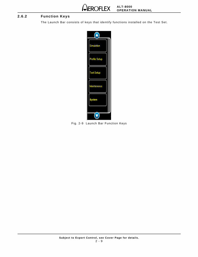
2.6.2 Function Keys
The Launch Bar consists of keys that ident i fy funct ions instal led on the Test Set.
F ig. 2-9 Launch Bar Funct ion Keys
ALT-8000OPERATION MANUAL
Subject to Export Control , see Cover Page for detai ls .2 - 10
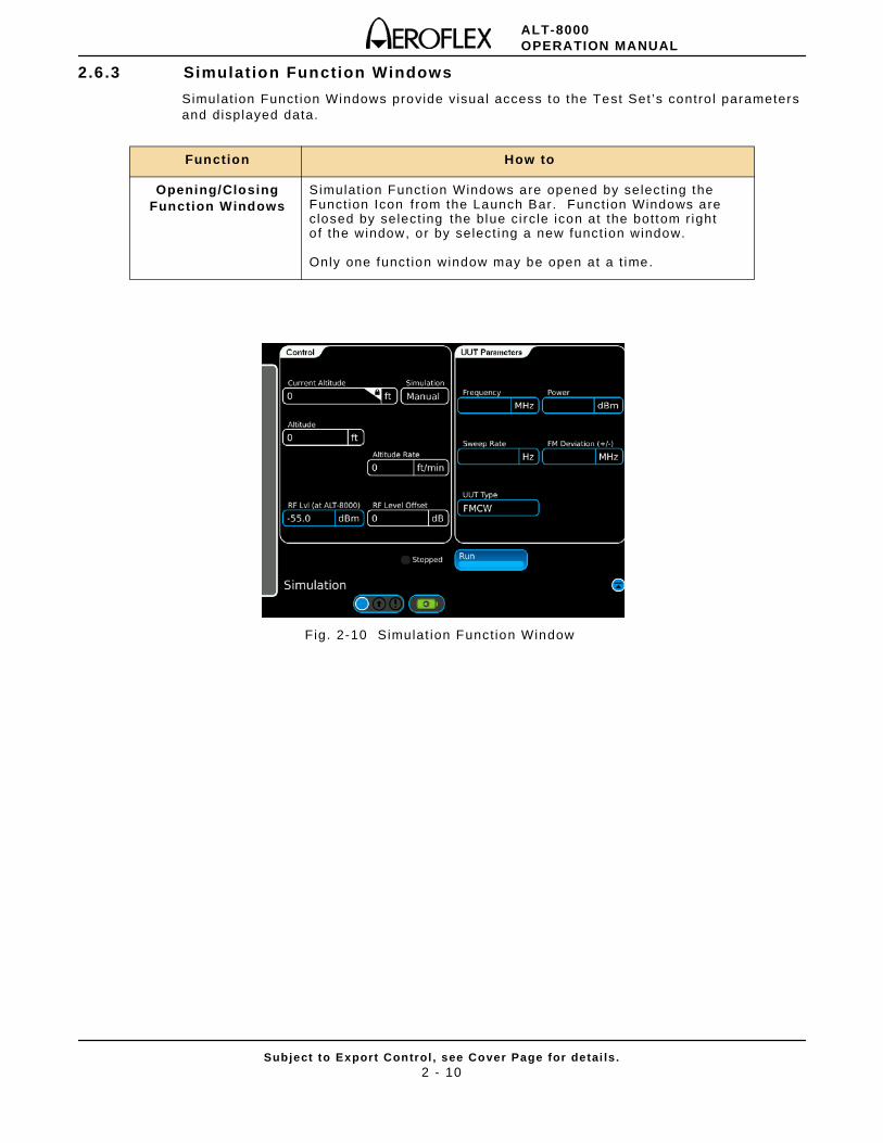
2.6.3 Simulation Function Windows
Simulat ion Funct ion Windows provide visual access to the Test Set ’s contro l parameters and displayed data.
Fig. 2-10 Simulat ion Funct ion Window
Function How to
Opening/Closing Function Windows
Simulat ion Funct ion Windows are opened by select ing the Funct ion Icon f rom the Launch Bar. Funct ion Windows are closed by select ing the blue circ le icon at the bottom r ight o f the window, or by select ing a new funct ion window.
Only one funct ion window may be open at a t ime.
ALT-8000OPERATION MANUAL
Subject to Export Control , see Cover Page for detai ls .2 - 11
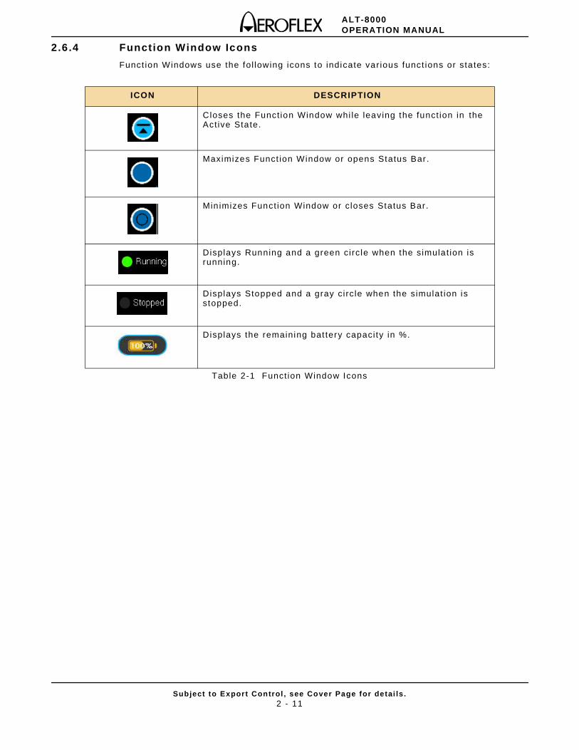
2.6.4 Function Window Icons
Funct ion Windows use the fol lowing icons to indicate var ious funct ions or sta tes:
Table 2-1 Funct ion Window Icons
ICON DESCRIPTION
Closes the Funct ion Window whi le leaving the funct ion in theAct ive State.
Maximizes Funct ion Window or opens Status Bar.
Min imizes Funct ion Window or c loses Status Bar.
Displays Running and a green circ le when the simulat ion is running.
Displays Stopped and a gray circ le when the simulat ion is stopped.
Displays the remaining bat tery capaci ty in %.
ALT-8000OPERATION MANUAL
Subject to Export Control , see Cover Page for detai ls .2 - 12
2.7 DEFINING PARAMETERS
2.7.1 Entering Numeric Values
Numeric values are used to def ine a var iety of test parameters such as frequency and level . When a numeric data f ie ld is se lected for edi t ing, a group of data entry pop-up windows is launched which provides three methods for def ining the value; Numer ic Keypad, Data Slew Bar or Rotary Knob.
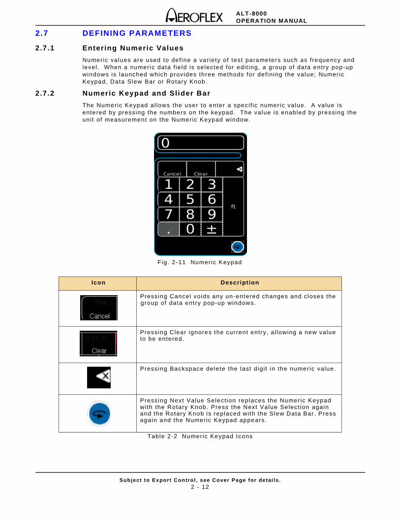
2.7.2 Numeric Keypad and Sl ider Bar
The Numer ic Keypad al lows the user to enter a speci f ic numeric value. A value is entered by pressing the numbers on the keypad. The value is enabled by pressing the uni t of measurement on the Numeric Keypad window.
Fig . 2-11 Numer ic Keypad
Table 2-2 Numer ic Keypad Icons
Icon Descript ion
Pressing Cancel voids any un-entered changes and closes the group of data entry pop-up windows.
Pressing Clear ignores the current entry, al lowing a new value to be entered.
Pressing Backspace delete the last digi t in the numer ic value.
Pressing Next Value Select ion replaces the Numeric Keypad with the Rotary Knob. Press the Next Value Select ion again and the Rotary Knob is replaced with the Slew Data Bar. Press again and the Numeric Keypad appears.
ALT-8000OPERATION MANUAL
Subject to Export Control , see Cover Page for detai ls .2 - 13
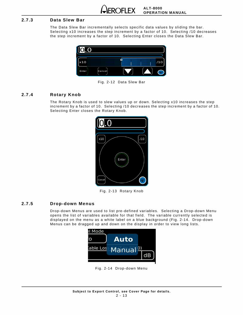
2.7.3 Data Slew Bar
The Data Slew Bar incrementa l ly selects speci f ic data values by sl id ing the bar. Select ing x10 increases the step increment by a factor o f 10. Select ing /10 decreases the step increment by a factor of 10. Select ing Enter c loses the Data Slew Bar.
Fig. 2-12 Data Slew Bar
2.7.4 Rotary Knob
The Rotary Knob is used to slew values up or down. Select ing x10 increases the step increment by a factor of 10. Select ing /10 decreases the step increment by a factor of 10. Select ing Enter c loses the Rotary Knob.
Fig. 2-13 Rotary Knob
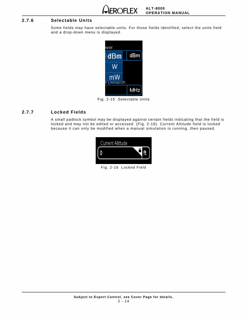
2.7.5 Drop-down Menus
Drop-down Menus are used to l ist pre-def ined var iables. Select ing a Drop-down Menu opens the l ist o f var iables avai lable for that f ie ld. The var iable current ly selected is displayed on the menu as a white label on a blue background (Fig. 2-14. Drop-down Menus can be dragged up and down on the d isplay in order to view long l ists.
Fig. 2-14 Drop-down Menu
ALT-8000OPERATION MANUAL
Subject to Export Control , see Cover Page for detai ls .2 - 14
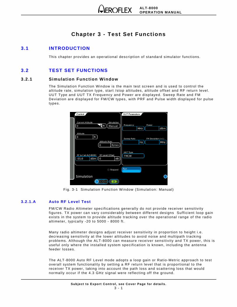
2.7.6 Selectable Units
Some f ie lds may have selectable uni ts. For those f ie lds ident i f ied, se lect the un i ts f ie ld and a drop-down menu is displayed.
F ig. 2-15 Selectab le Units
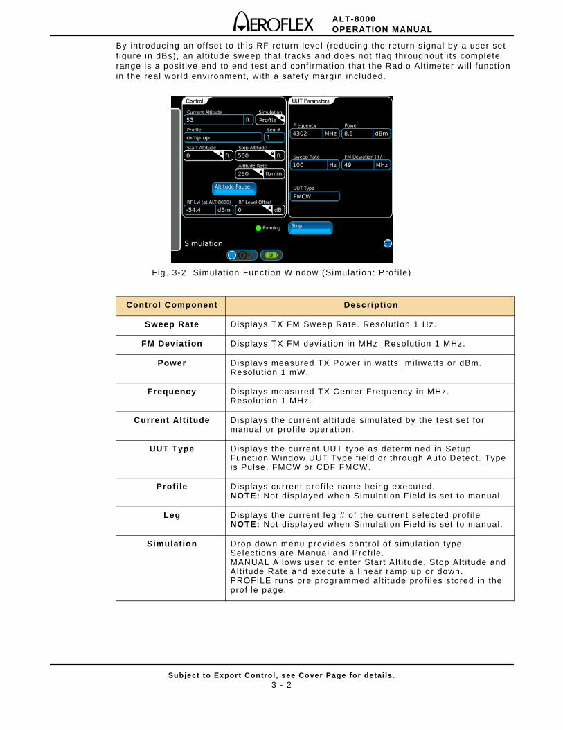
2.7.7 Locked Fields
A smal l padlock symbol may be displayed against cer tain f ie lds ind icat ing that the f ie ld is locked and may not be edi ted or accessed (Fig. 2-16) . Current Al t i tude f ie ld is locked because i t can only be modi f ied when a manual s imulat ion is running, then paused.
Fig. 2-16 Locked Field
ALT-8000OPERATION MANUAL
Subject to Export Control , see Cover Page for detai ls .3 - 1
Chapter 3 - Test Set Functions
3.1 INTRODUCTION
This chapter provides an operat ional descr ipt ion of standard simulator funct ions.
3.2 TEST SET FUNCTIONS
3.2.1 Simulation Function Window
The Simulat ion Funct ion Window is the main test screen and is used to control the al t i tude rate, s imulat ion type, star t /stop al t i tudes, al t i tude offset and RF return level . UUT Type and UUT TX Frequency and Power are d isplayed. Sweep Rate and FM Deviat ion are displayed for FM/CW types, with PRF and Pulse width displayed for pulse types.
Fig. 3-1 Simulat ion Funct ion Window (Simulat ion: Manual)
3.2.1.A Auto RF Level Test
FM/CW Radio Alt imeter speci f icat ions general ly do not provide receiver sensi t iv i ty f igures. TX power can vary considerably between di f ferent designs Suff ic ient loop gain exists in the system to provide al t i tude tracking over the operat ional range of the radio al t imeter, typ ical ly -20 to 5000 - 8000 f t .
Many radio al t imeter designs adjust receiver sensi t iv i ty in propor t ion to height i .e . decreasing sensi t iv i ty at the lower al t i tudes to avoid noise and mult ipath tracking problems. Al though the ALT-8000 can measure receiver sensi t iv i ty and TX power, th is is useful only where the instal led system speci f icat ion is known, including the antenna feeder losses.
The ALT-8000 Auto RF Level mode adopts a loop gain or Rat io-Metr ic approach to test overa l l system funct ional i ty by set t ing a RF return level that is proport ional to the receiver TX power, taking into account the path loss and scatter ing loss that would normal ly occur i f the 4.3 GHz signal were ref lect ing off the ground.
ALT-8000OPERATION MANUAL
Subject to Export Control , see Cover Page for detai ls .3 - 2
By introducing an of fset to this RF return level ( reducing the return signal by a user set f igure in dBs), an al t i tude sweep that t racks and does not f lag throughout i ts complete range is a posi t ive end to end test and conf i rmat ion that the Radio Alt imeter wi l l funct ion in the real wor ld envi ronment, wi th a safety margin included.
Fig . 3-2 Simulat ion Funct ion Window (Simulat ion: Prof i le)
Control Component Description
Sweep Rate Displays TX FM Sweep Rate. Resolut ion 1 Hz.
FM Deviat ion Displays TX FM deviat ion in MHz. Resolut ion 1 MHz.
Power Displays measured TX Power in watts, mi l iwatts or dBm.Resolut ion 1 mW.
Frequency Displays measured TX Center Frequency in MHz.Resolut ion 1 MHz.
Current Alt itude Displays the current al t i tude simulated by the test set for manual or prof i le operat ion.
UUT Type Displays the current UUT type as determined in Setup Funct ion Window UUT Type f ie ld or through Auto Detect. Type is Pulse, FMCW or CDF FMCW.
Profi le Displays current prof i le name being executed.NOTE: Not displayed when Simulat ion F ield is set to manual.
Leg Displays the current leg # of the current selected prof i leNOTE: Not displayed when Simulat ion F ield is set to manual.
Simulation Drop down menu provides control o f s imulat ion type. Select ions are Manual and Prof i le.MANUAL Al lows user to enter Start Al t i tude, Stop Al t i tude and Alt i tude Rate and execute a l inear ramp up or down.PROFILE runs pre programmed al t i tude prof i les stored in the prof i le page.
ALT-8000OPERATION MANUAL
Subject to Export Control , see Cover Page for detai ls .3 - 3
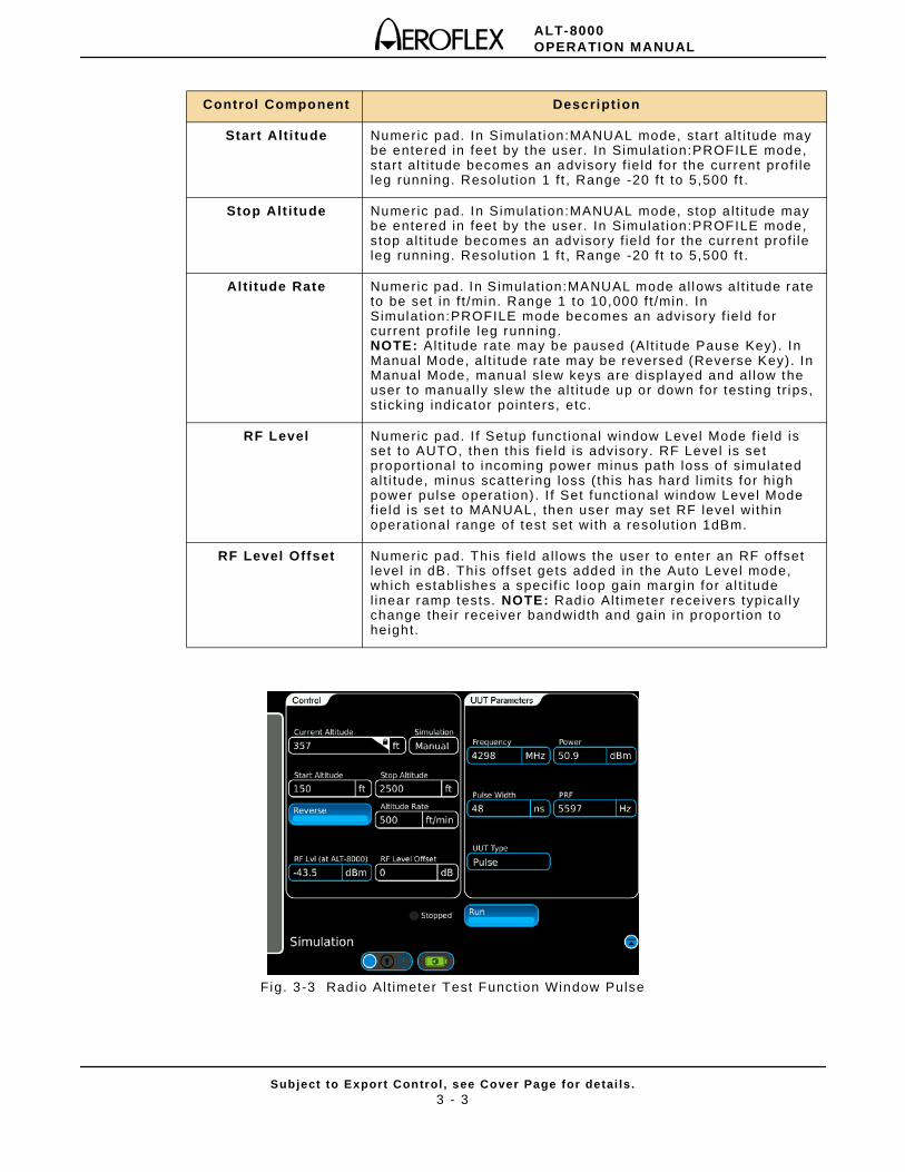
Fig. 3-3 Radio Al t imeter Test Funct ion Window Pulse
Control Component Description
Start Alti tude Numeric pad. In Simulat ion:MANUAL mode, start al t i tude may be entered in feet by the user. In Simulat ion:PROFILE mode, star t al t i tude becomes an advisory f ie ld for the current prof i le leg running. Resolut ion 1 f t , Range -20 f t to 5,500 f t .
Stop Alt itude Numeric pad. In Simulat ion:MANUAL mode, stop a l t i tude may be entered in feet by the user. In Simulat ion:PROFILE mode, stop al t i tude becomes an advisory f ie ld for the current prof i le leg running. Resolut ion 1 f t , Range -20 f t to 5,500 f t .
Altitude Rate Numeric pad. In Simulat ion:MANUAL mode al lows al t i tude rate to be set in f t /min. Range 1 to 10,000 f t /min. In Simulat ion:PROFILE mode becomes an advisory f ie ld for current prof i le leg running.NOTE: Alt i tude rate may be paused (Alt i tude Pause Key) . In Manual Mode, al t i tude rate may be reversed (Reverse Key). In Manual Mode, manual s lew keys are displayed and al low the user to manual ly s lew the al t i tude up or down for test ing tr ips, st icking indicator pointers, etc.
RF Level Numeric pad. I f Setup funct ional window Level Mode f ie ld is set to AUTO, then th is f ie ld is advisory. RF Level is set proport ional to incoming power minus path loss of s imulated al t i tude, minus scatter ing loss ( this has hard l imits for high power pulse operat ion) . I f Set funct ional window Level Mode f ie ld is set to MANUAL, then user may set RF level wi thin operat ional range of test set wi th a resolut ion 1dBm.
RF Level Offset Numeric pad. This f ie ld a l lows the user to enter an RF offset level in dB. This of fset gets added in the Auto Level mode, which establ ishes a speci f ic loop gain margin for al t i tude l inear ramp tests. NOTE: Radio Al t imeter receivers typical ly change thei r receiver bandwidth and gain in propor t ion to height.
ALT-8000OPERATION MANUAL
Subject to Export Control , see Cover Page for detai ls .3 - 4
3.2.1.B Pulse Radio Alt imeters
The fol lowing UUT parameters are displayed when test ing pulse radio al t imeters:
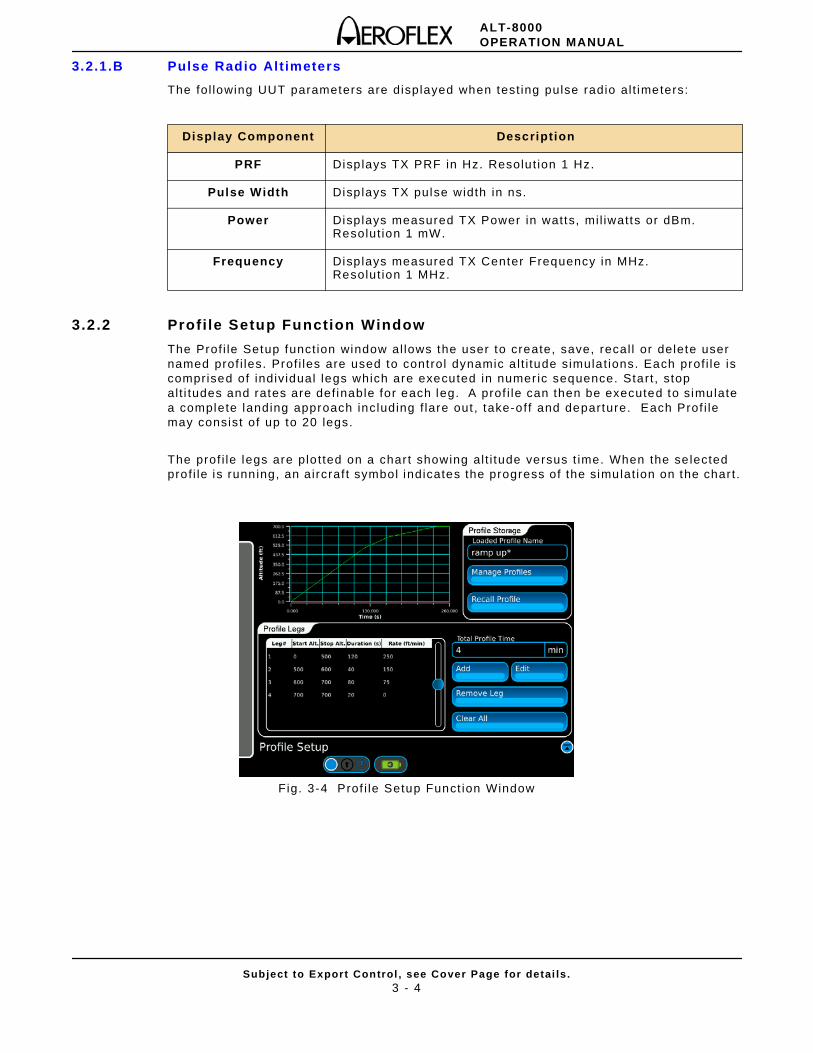
3.2.2 Profi le Setup Function Window
The Prof i le Setup funct ion window al lows the user to create, save, recal l or delete user named prof i les. Prof i les are used to control dynamic a l t i tude simulat ions. Each prof i le is comprised of indiv idual legs which are executed in numer ic sequence. Start , stop al t i tudes and rates are def inable for each leg. A prof i le can then be executed to simulate a complete landing approach including f lare out , take-off and departure. Each Prof i le may consist of up to 20 legs.
The prof i le legs are plo t ted on a char t showing al t i tude versus t ime. When the se lected prof i le is running, an aircraf t symbol indicates the progress of the simulat ion on the char t .
Fig. 3-4 Prof i le Setup Funct ion Window
Display Component Description
PRF Displays TX PRF in Hz. Resolut ion 1 Hz.
Pulse Width Displays TX pulse width in ns.
Power Displays measured TX Power in watts, mi l iwatts or dBm.Resolut ion 1 mW.
Frequency Displays measured TX Center Frequency in MHz.Resolut ion 1 MHz.
ALT-8000OPERATION MANUAL
Subject to Export Control , see Cover Page for detai ls .3 - 5
3.2.2.A Add Leg # Window
The Add Leg # Window is used to enter data for new legs in a prof i le. To create a new leg, select the “Add New Leg” l ine in the prof i le table to open the Add Leg # window.
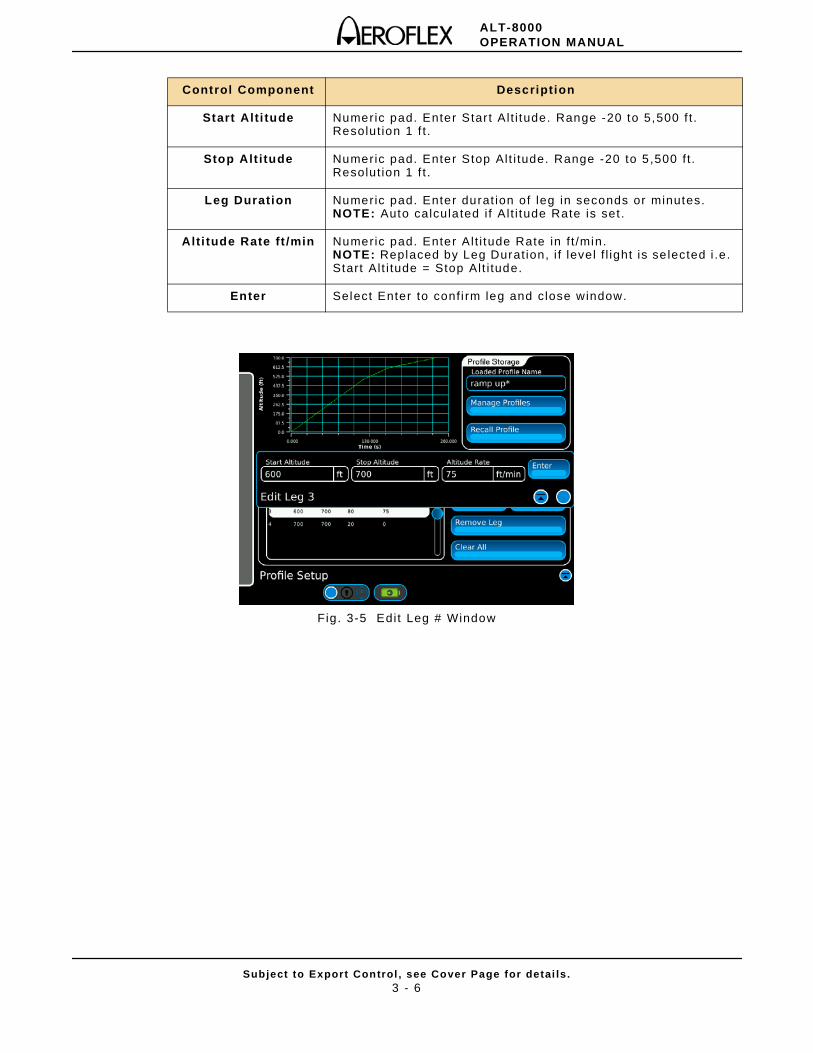
3.2.2.B Edit Leg # Window
To edit an exist ing leg, select the desired l ine in the prof i le tab le and select the Edit Leg key to display the Edit Leg # window (Fig. 3-5).
NOTE: When adding a new leg, the Start Al t i tude f ie ld wi l l automat ical ly display an entry equal to the Stop Alt i tude def ined in the previous leg. This may be overwri t ten to create a step a l t i tude i f required. The Alt i tude Rate may be set for each leg, which wi l l resul t in an auto calcula t ion for Leg Durat ion being displayed.
NOTE: I f level f l ight is required for a speci f ic leg, set the Start and Stop a l t i tudes to be equal. The Al t i tude Rate f ie ld wi l l be replaced by the Leg Durat ion f ie ld. Enter the requi red durat ion of level f l ight in the Leg Durat ion f ie ld in seconds.
Control Component Description
Add Displays Add Leg # window.
Edit Displays Edit Leg # window.
Remove Leg Deletes the se lected leg in the current prof i le table .
Clear Al l Deletes al l legs in the current prof i le table.
Manage Profi les Displays the Manage Prof i les Funct ion Window.
Recall Profi le Displays the Load Prof i le Funct ion Window.
Display Component Description
Loaded Profi le Name Displays current prof i le name.
Total Profi le Time Displays the to tal durat ion of the current prof i le in minutes.
Leg # Displays leg number.
Start Alt Displays Start Al t i tude. Range -20 to 5 ,500 f t . Resolut ion 1 f t .
Stop Alt Displays Stop Alt Range -20 to 5,500 f t . Resolut ion 1 f t .
Duration (s) Displays durat ion of leg in seconds (auto calculated i f Al t i tude Rate is set) .
Rate (f t /min) Displays Al t i tude Rate in f t /min. Range 1 to 10,000 f t /min.
ALT-8000OPERATION MANUAL
Subject to Export Control , see Cover Page for detai ls .3 - 6
Fig. 3-5 Edit Leg # Window
Control Component Description
Start Alti tude Numeric pad. Enter Star t Al t i tude. Range -20 to 5,500 f t . Resolut ion 1 f t .
Stop Alt itude Numeric pad. Enter Stop Alt i tude. Range -20 to 5 ,500 f t . Resolut ion 1 f t .
Leg Duration Numeric pad. Enter durat ion of leg in seconds or minutes. NOTE: Auto calcula ted i f A l t i tude Rate is set .
Alti tude Rate ft /min Numeric pad. Enter Al t i tude Rate in f t /min. NOTE: Replaced by Leg Durat ion, i f level f l ight is se lected i .e. Start Al t i tude = Stop Alt i tude.
Enter Select Enter to conf i rm leg and close window.
ALT-8000OPERATION MANUAL
Subject to Export Control , see Cover Page for detai ls .3 - 7
3.2.3 Profi le Management
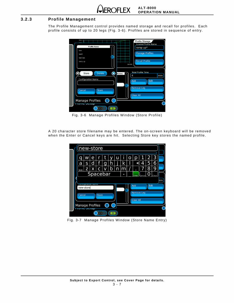
The Prof i le Management control provides named storage and recal l for prof i les. Each prof i le consists o f up to 20 legs (F ig. 3-6) . Prof i les are stored in sequence of entry.
Fig. 3-6 Manage Prof i les Window (Store Prof i le)
A 20 character store f i lename may be entered. The on-screen keyboard wi l l be removed when the Enter or Cancel keys are hi t . Select ing Store key stores the named prof i le .
Fig. 3-7 Manage Prof i les Window (Store Name Entry)
ALT-8000OPERATION MANUAL
Subject to Export Control , see Cover Page for detai ls .3 - 8
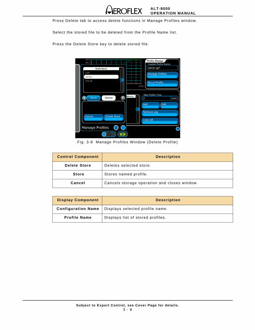
Press Delete tab to access delete funct ions in Manage Prof i les window.
Select the stored f i le to be deleted from the Prof i le Name l ist .
Press the Delete Store key to delete stored f i le.
Fig . 3-8 Manage Prof i les Window (Delete Prof i le)
Control Component Description
Delete Store Deletes selected store.
Store Stores named prof i le.
Cancel Cancels storage operat ion and closes window.
Display Component Description
Configurat ion Name Displays selected prof i le name.
Profi le Name Displays l ist of stored prof i les.
ALT-8000OPERATION MANUAL
Subject to Export Control , see Cover Page for detai ls .3 - 9
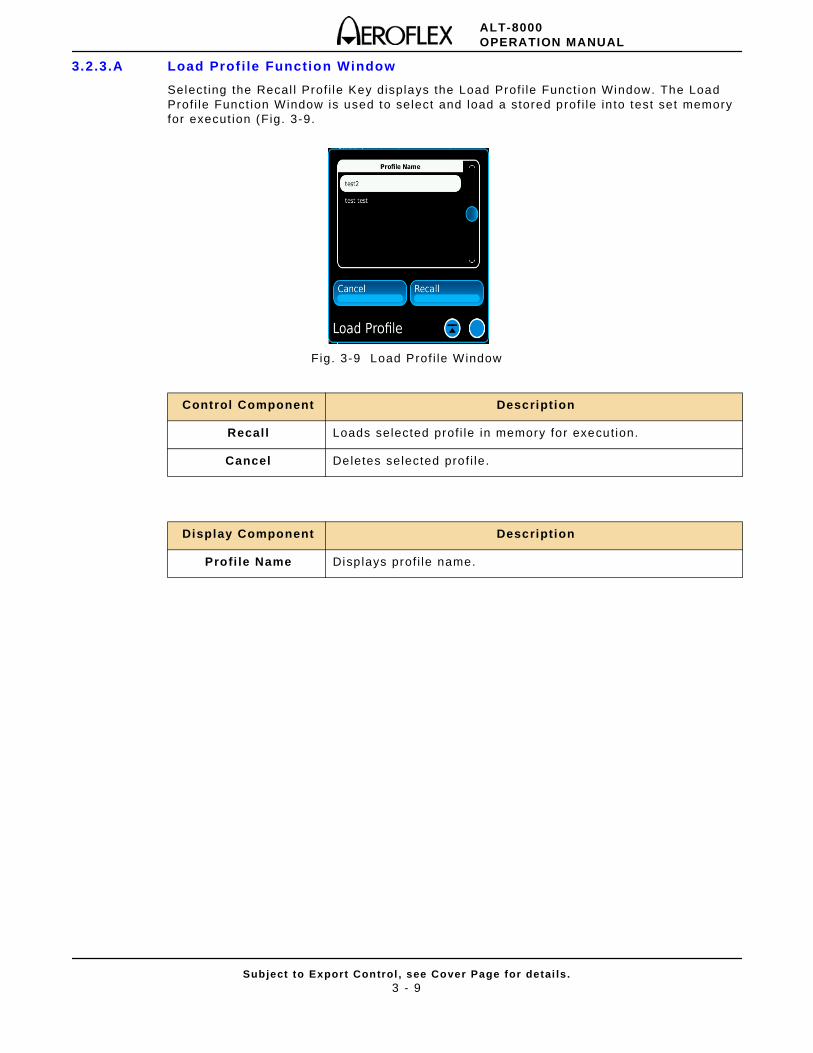
3.2.3.A Load Prof i le Function Window
Select ing the Recal l Prof i le Key displays the Load Prof i le Funct ion Window. The Load Prof i le Funct ion Window is used to select and load a stored prof i le in to test set memory for execut ion (Fig. 3-9.
Fig. 3-9 Load Prof i le Window
Control Component Description
Recal l Loads selected prof i le in memory for execut ion.
Cancel Deletes selected prof i le.
Display Component Description
Profi le Name Displays prof i le name.
ALT-8000OPERATION MANUAL
Subject to Export Control , see Cover Page for detai ls .3 - 10
3.3 TEST SETUP
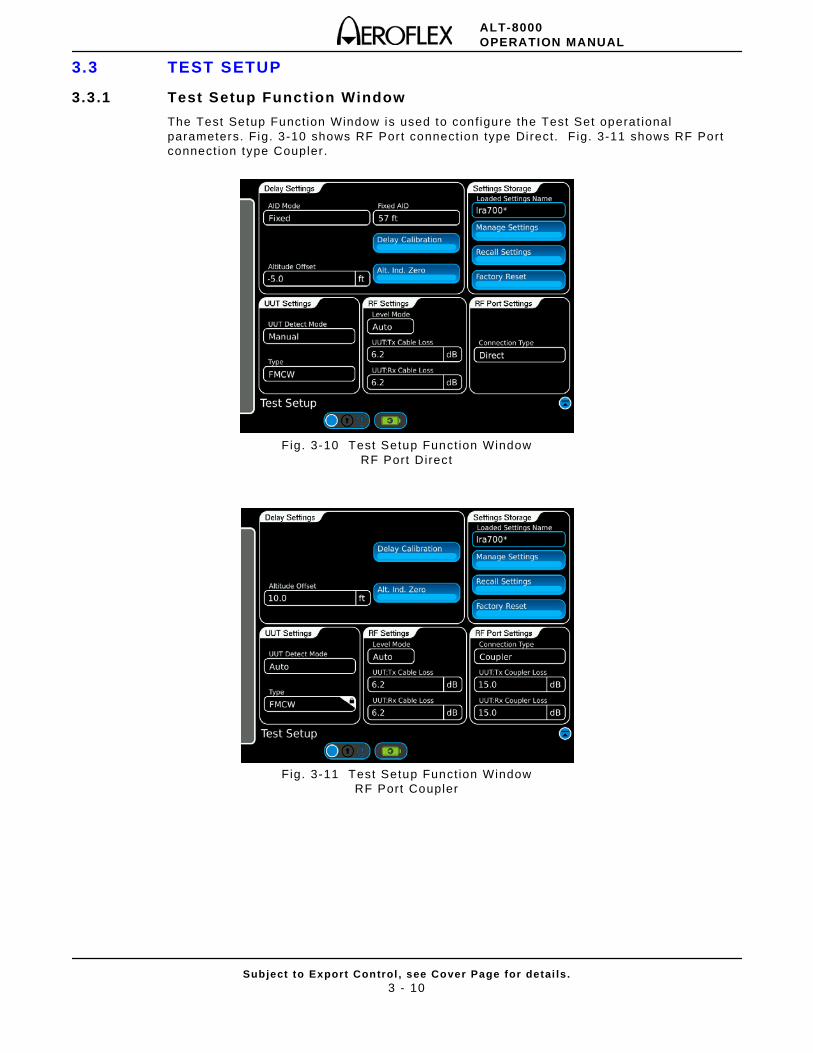
3.3.1 Test Setup Function Window
The Test Setup Funct ion Window is used to conf igure the Test Set operat ional parameters. Fig. 3-10 shows RF Port connect ion type Di rect. F ig. 3-11 shows RF Port connect ion type Coupler .
Fig. 3-10 Test Setup Funct ion Window RF Port Direct
Fig. 3-11 Test Setup Funct ion Window RF Port Coupler
ALT-8000OPERATION MANUAL
Subject to Export Control , see Cover Page for detai ls .3 - 11
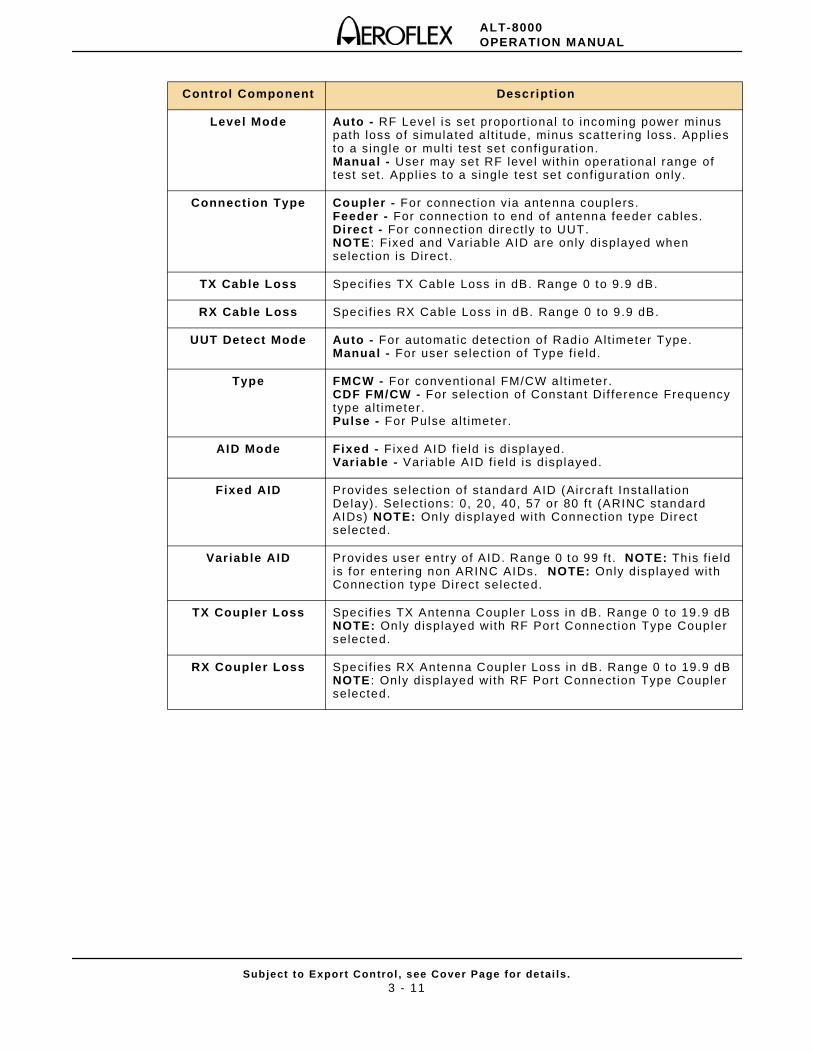
Control Component Description
Level Mode Auto - RF Level is set proport ional to incoming power minus path loss of s imulated a l t i tude, minus scat ter ing loss. Appl ies to a single or mult i test set conf igurat ion. Manual - User may set RF level wi th in operat ional range of test set. Appl ies to a single test set conf igurat ion only.
Connection Type Coupler - For connect ion via antenna couplers. Feeder - For connect ion to end of antenna feeder cables. Direct - For connect ion direct ly to UUT. NOTE : Fixed and Variable AID are only displayed when select ion is Direct.
TX Cable Loss Specif ies TX Cable Loss in dB. Range 0 to 9.9 dB.
RX Cable Loss Specif ies RX Cable Loss in dB. Range 0 to 9 .9 dB.
UUT Detect Mode Auto - For automat ic detect ion of Radio Al t imeter Type. Manual - For user select ion of Type f ie ld.
Type FMCW - For convent ional FM/CW alt imeter. CDF FM/CW - For select ion of Constant Dif ference Frequency type al t imeter. Pulse - For Pulse al t imeter.
AID Mode Fixed - Fixed AID f ie ld is disp layed. Variable - Var iable AID f ie ld is displayed.
Fixed AID Provides se lect ion of standard AID (Aircraft Instal lat ion Delay). Select ions: 0, 20, 40, 57 or 80 f t (ARINC standard AIDs) NOTE: Only displayed with Connect ion type Direct selected.
Variable AID Provides user entry of AID. Range 0 to 99 f t . NOTE: This f ie ld is for enter ing non ARINC AIDs. NOTE: Only d isplayed with Connect ion type Di rect selected.
TX Coupler Loss Specif ies TX Antenna Coupler Loss in dB. Range 0 to 19.9 dB NOTE: Only displayed with RF Port Connect ion Type Coupler selected.
RX Coupler Loss Specif ies RX Antenna Coupler Loss in dB. Range 0 to 19.9 dB NOTE : Only displayed with RF Port Connect ion Type Coupler selected.
ALT-8000OPERATION MANUAL
Subject to Export Control , see Cover Page for detai ls .3 - 12
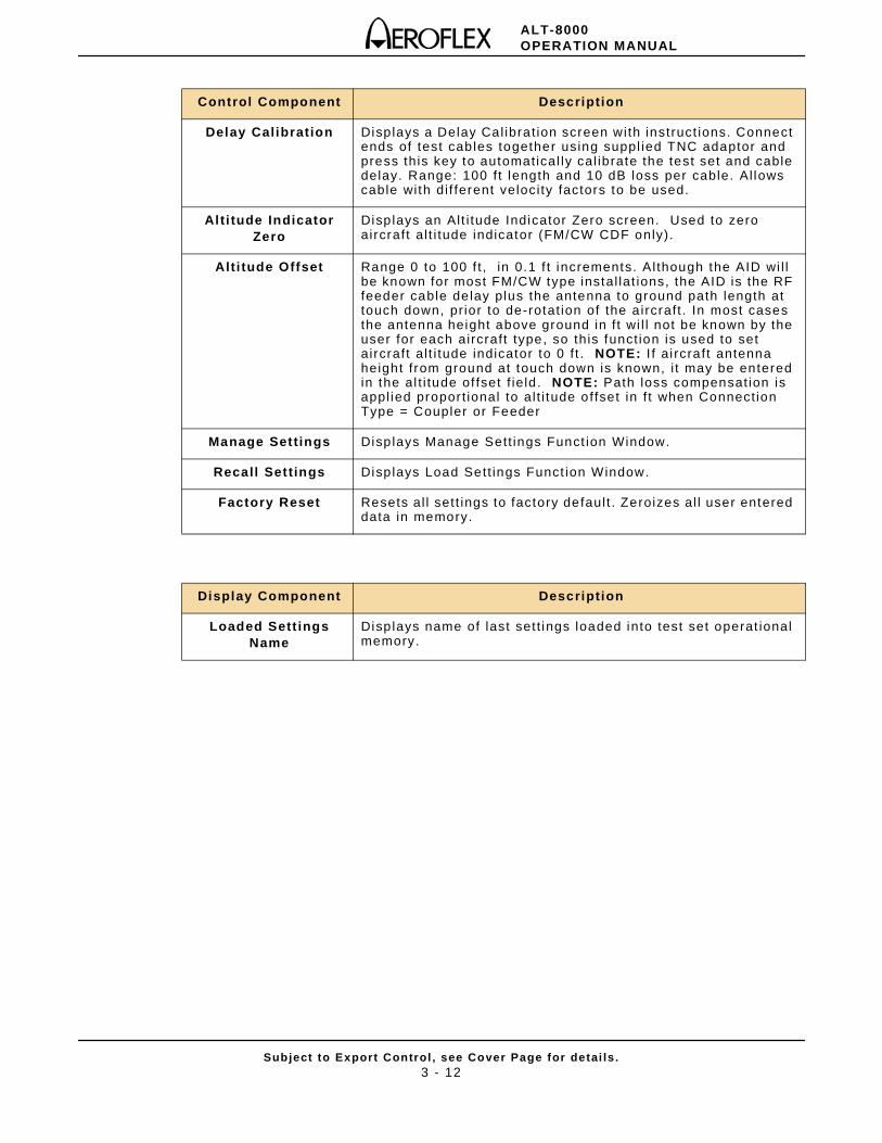
Control Component Description
Delay Calibration Displays a Delay Cal ibrat ion screen with instruct ions. Connect ends of test cables together using suppl ied TNC adaptor and press this key to automatical ly cal ibrate the test set and cable delay. Range: 100 f t length and 10 dB loss per cable. Al lows cable with di f ferent veloci ty factors to be used.
Alti tude IndicatorZero
Displays an Alt i tude Indicator Zero screen. Used to zero aircraft al t i tude indicator (FM/CW CDF only).
Alti tude Offset Range 0 to 100 f t , in 0.1 f t increments. Al though the AID wi l l be known for most FM/CW type instal lat ions, the AID is the RF feeder cable de lay plus the antenna to ground path length at touch down, pr ior to de-rotat ion of the a ircraft . In most cases the antenna height above ground in f t wi l l not be known by the user for each aircraft type, so this funct ion is used to set aircraft al t i tude indicator to 0 f t . NOTE: I f a i rcraft antenna height f rom ground at touch down is known, i t may be entered in the al t i tude of fset f ie ld . NOTE: Path loss compensat ion is appl ied propor t ional to al t i tude offset in f t when Connect ion Type = Coupler or Feeder
Manage Settings Displays Manage Sett ings Funct ion Window.
Recall Settings Displays Load Sett ings Funct ion Window.
Factory Reset Resets al l sett ings to factory defaul t . Zeroizes al l user entered data in memory.
Display Component Description
Loaded Sett ingsName
Displays name of last sett ings loaded into test set operat ional memory.
ALT-8000OPERATION MANUAL
Subject to Export Control , see Cover Page for detai ls .3 - 13
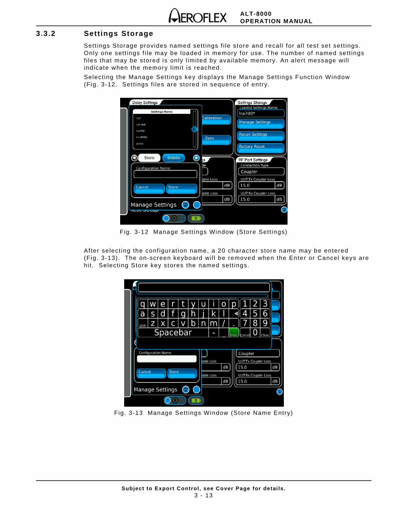
3.3.2 Settings Storage
Set t ings Storage provides named sett ings f i le store and recal l for al l test set sett ings. Only one sett ings f i le may be loaded in memory for use. The number of named sett ings f i les that may be stored is only l imited by avai lable memory. An a lert message wi l l indicate when the memory l imi t is reached.
Select ing the Manage Sett ings key displays the Manage Sett ings Funct ion Window (Fig. 3-12. Sett ings f i les are stored in sequence of ent ry.
Fig. 3-12 Manage Sett ings Window (Store Sett ings)
Af ter select ing the conf igurat ion name, a 20 character store name may be entered (Fig. 3-13). The on-screen keyboard wi l l be removed when the Enter or Cancel keys are hi t . Select ing Store key stores the named set t ings.
Fig. 3-13 Manage Sett ings Window (Store Name Entry)
ALT-8000OPERATION MANUAL
Subject to Export Control , see Cover Page for detai ls .3 - 14
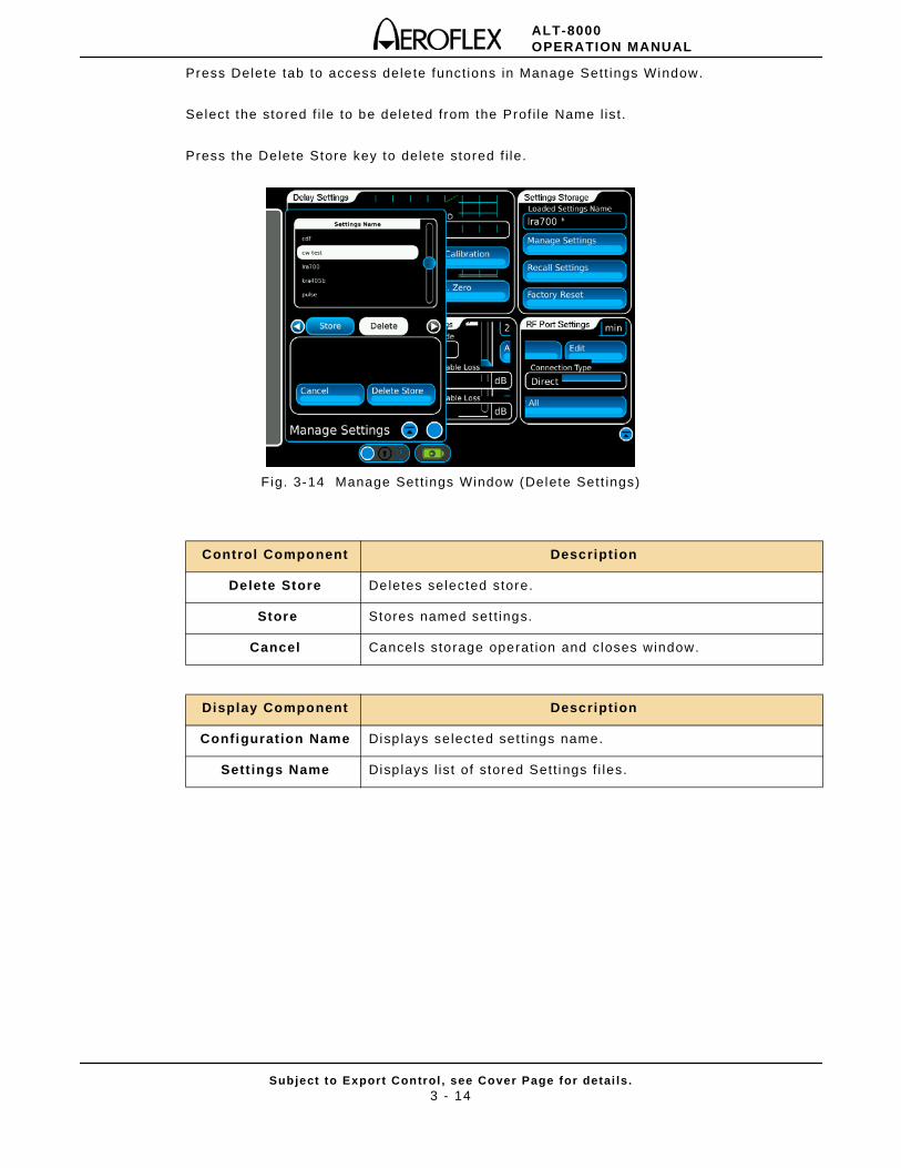
Press Delete tab to access delete funct ions in Manage Sett ings Window.
Select the stored f i le to be deleted from the Prof i le Name l ist .
Press the Delete Store key to delete stored f i le.
Fig. 3-14 Manage Set t ings Window (Delete Sett ings)
Control Component Description
Delete Store Deletes selected store.
Store Stores named set t ings.
Cancel Cancels storage operat ion and closes window.
Display Component Description
Configurat ion Name Displays selected set t ings name.
Sett ings Name Displays l ist of stored Sett ings f i les.
ALT-8000OPERATION MANUAL
Subject to Export Control , see Cover Page for detai ls .3 - 15
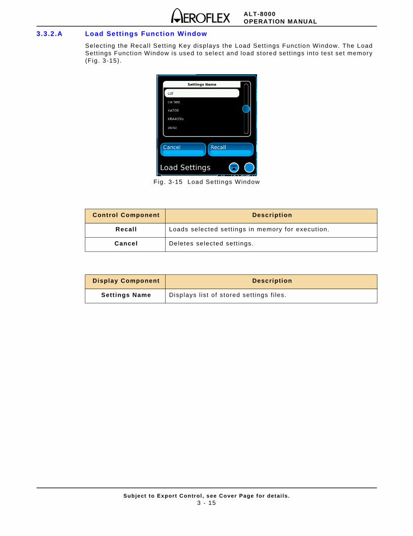
3.3.2.A Load Settings Function Window
Select ing the Recal l Sett ing Key displays the Load Sett ings Funct ion Window. The Load Set t ings Funct ion Window is used to select and load stored sett ings into test set memory (Fig. 3-15) .
F ig. 3-15 Load Sett ings Window
Control Component Description
Recal l Loads selected sett ings in memory for execut ion.
Cancel Deletes selected sett ings.
Display Component Description
Sett ings Name Displays l ist of stored set t ings f i les.
ALT-8000OPERATION MANUAL
Subject to Export Control , see Cover Page for detai ls .3 - 16
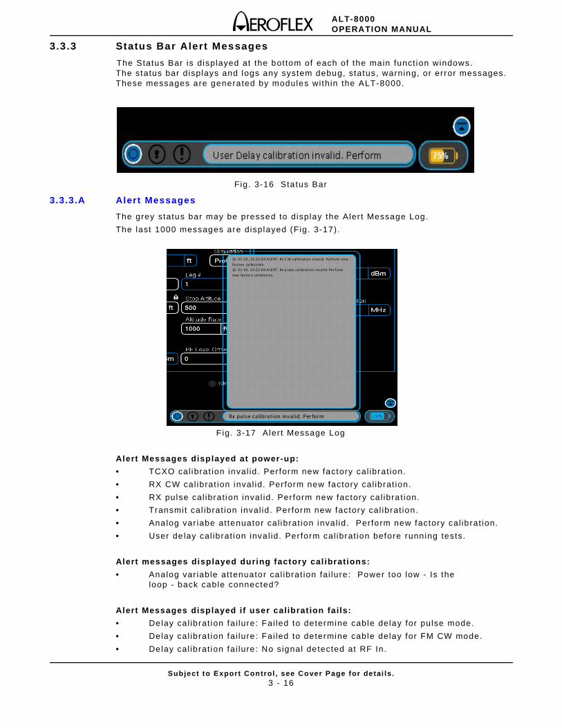
3.3.3 Status Bar Alert Messages
The Status Bar is displayed at the bottom of each of the main funct ion windows. The status bar displays and logs any system debug, status, warning, or error messages. These messages are generated by modules within the ALT-8000.
Fig. 3-16 Status Bar
3.3.3.A Alert Messages
The grey status bar may be pressed to display the Aler t Message Log.
The last 1000 messages are displayed (Fig. 3-17).
F ig. 3-17 Alert Message Log
Alert Messages displayed at power-up:
• TCXO cal ibrat ion inval id. Per form new factory cal ibrat ion.
• RX CW cal ibrat ion inval id. Per form new factory cal ibrat ion.
• RX pulse cal ibrat ion inval id. Per form new factory ca l ibrat ion.
• Transmit cal ibrat ion inval id. Perform new factory cal ibrat ion.
• Analog var iabe attenuator cal ibrat ion inval id. Perform new factory cal ibrat ion.
• User de lay cal ibrat ion inva l id. Per form cal ibrat ion before running tests.
Alert messages displayed during factory cal ibrations:
• Analog var iable attenuator cal ibrat ion fai lure: Power too low - Is the loop - back cable connected?
Alert Messages displayed if user calibrat ion fails:
• Delay cal ibrat ion fai lure: Fai led to determine cable delay for pulse mode.
• Delay cal ibrat ion fai lure: Fai led to determine cable delay for FM CW mode.
• Delay cal ibrat ion fai lure: No signal detected at RF In.
12- 31-10, 13:22:03 A LERT: Rx C W c alibrat ion inva lid. Perf orm new fa ctory calibrat ion. 12- 31-10, 13:22:04 A LERT: Rx p ulse cal ibrat ion invalid. Perf orm new factory calibrat ion.
Rx pulse calibration inv alid. Per form
ALT-8000OPERATION MANUAL
Subject to Export Control , see Cover Page for detai ls .3 - 17
Alert Messages displayed when a test is started:
• UUT center f requency too low. Test stopping.
• UUT center f requency too high. Test stopping.
• UUT transmit f requency too low. UUT measurements cont inue but no RF is output.
• UUT transmi t f requency too high. UUT measurements cont inue but no RF is output.
• Unable to detect reasonable UUT signal. Test ing stopped.
• Signal at RF In is CW. We recommend stopping the test , checking the UUT connect ions and re-star t ing the test .
• Auto UUT detect is not yet implemented. Aerof lex recommends stopping the test and select ing manual UUT detect .
• Power too low at RF In. Test ing stopped.
Alert Messages displayed when a test is started (cont):
• Pulse Power too low at RF In . Test ing stopped.
• Inval id Pulse UUT Detected. Test ing stopped.
I f UUT Detect Mode is manual:
• User speci f ied UUT type (FMCW) does not match detected UUT type (CDF FMCW).
• User speci f ied UUT type (CDF FMCW) does not match detected UUT type (FMCW).
• User speci f ied UUT type (FMCW/CDF) does not match detected UUT type (PULSE).
• Pulses not detected. Check that the pu lse radio is connected correct ly.
Alert Messages displayed during store/recal l:
• Store Prof i le window open : please close window and try again.
• Load Prof i le window open : please close window and try again.
• Store Set t ings window open : please close window and try again.
• Load Set t ings window open : please close window and try again.

ALT-8000OPERATION MANUAL
Subject to Export Control , see Cover Page for detai ls .3 - 18
THIS PAGE INTENTIONALLY LEFT BLANK.
ALT-8000OPERATION MANUAL
Subject to Export Control , see Cover Page for detai ls .4 - 1
Chapter 4 - Test ing
4.1 INTRODUCTION
This chapter provides detai ls of standard tests for Radio Al t imeter receivers.
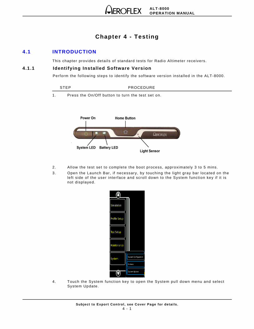
4.1.1 Identifying Installed Software Version
Perform the fol lowing steps to ident i fy the software version instal led in the ALT-8000.
STEP PROCEDURE
1. Press the On/Off but ton to turn the test set on.
2. Al low the test set to complete the boot process, approximately 3 to 5 mins.
3. Open the Launch Bar, i f necessary, by touching the l ight gray bar located on the lef t s ide of the user inter face and scrol l down to the System funct ion key i f i t is not displayed.
4. Touch the System funct ion key to open the System pul l down menu and select System Update.
ALT-8000OPERATION MANUAL
Subject to Export Control , see Cover Page for detai ls .4 - 2
STEP PROCEDURE
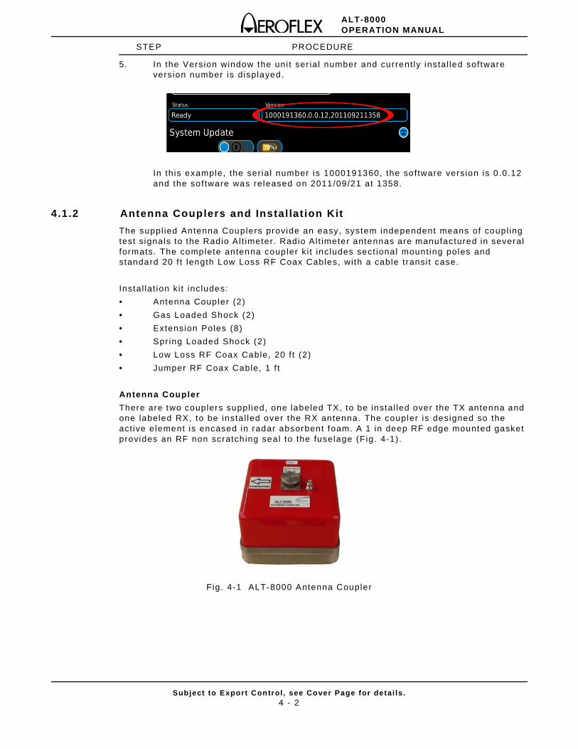
5. In the Version window the uni t ser ial number and current ly instal led software version number is displayed.
In this example, the ser ial number is 1000191360, the software version is 0 .0.12 and the software was released on 2011/09/21 at 1358.
4.1.2 Antenna Couplers and Instal lat ion Kit
The suppl ied Antenna Couplers provide an easy, system independent means of coupl ing test signals to the Radio Al t imeter. Radio Alt imeter antennas are manufactured in several formats. The complete antenna coupler k i t includes sect ional mount ing poles and standard 20 f t length Low Loss RF Coax Cables, wi th a cable transi t case.
Instal lat ion ki t includes:
• Antenna Coupler (2)
• Gas Loaded Shock (2)
• Extension Poles (8)
• Spr ing Loaded Shock (2)
• Low Loss RF Coax Cable, 20 f t (2)
• Jumper RF Coax Cable, 1 f t
Antenna Coupler
There are two couplers suppl ied, one labeled TX, to be instal led over the TX antenna and one labeled RX, to be insta l led over the RX antenna. The coupler is designed so the act ive element is encased in radar absorbent foam. A 1 in deep RF edge mounted gasket provides an RF non scratch ing seal to the fuselage (Fig. 4-1) .
Fig. 4-1 ALT-8000 Antenna Coupler
ALT-8000OPERATION MANUAL
Subject to Export Control , see Cover Page for detai ls .4 - 3
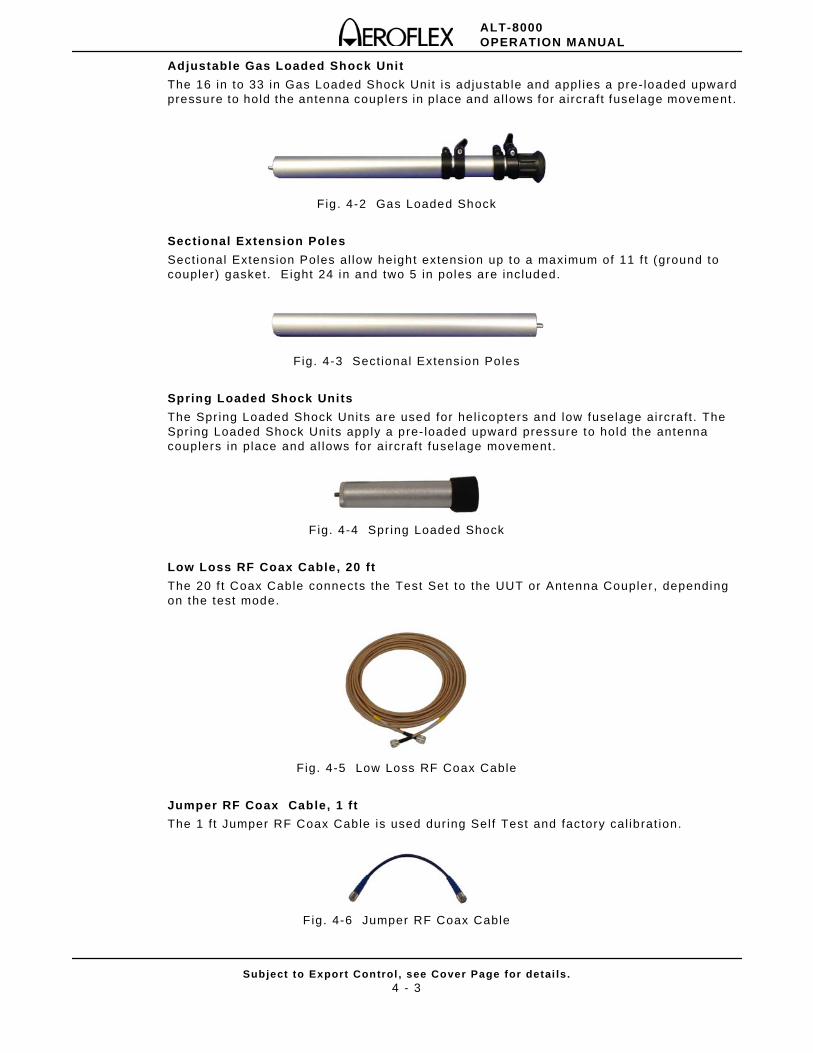
Adjustable Gas Loaded Shock Unit
The 16 in to 33 in Gas Loaded Shock Unit is adjustable and appl ies a pre- loaded upward pressure to hold the antenna couplers in place and al lows for aircraft fuselage movement .
Fig . 4-2 Gas Loaded Shock
Sectional Extension Poles
Sect ional Extension Poles al low height extension up to a maximum of 11 f t (ground to coupler) gasket. E ight 24 in and two 5 in poles are included.
Fig. 4-3 Sect ional Extension Poles
Spring Loaded Shock Units
The Spr ing Loaded Shock Units are used for hel icopters and low fuselage ai rcraft . The Spr ing Loaded Shock Uni ts apply a pre- loaded upward pressure to hold the antenna couplers in place and al lows for aircraft fuselage movement.
F ig. 4-4 Spr ing Loaded Shock
Low Loss RF Coax Cable, 20 ft
The 20 f t Coax Cable connects the Test Set to the UUT or Antenna Coupler , depending on the test mode.
Fig. 4-5 Low Loss RF Coax Cable
Jumper RF Coax Cable, 1 f t
The 1 f t Jumper RF Coax Cable is used dur ing Self Test and factory cal ibrat ion.
F ig. 4-6 Jumper RF Coax Cable
ALT-8000OPERATION MANUAL
Subject to Export Control , see Cover Page for detai ls .4 - 4
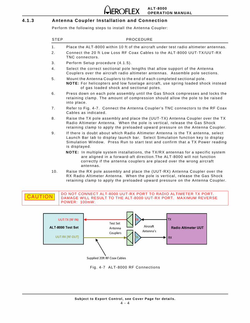
4.1.3 Antenna Coupler Instal lat ion and Connection
Perform the fol lowing steps to instal l the Antenna Coupler :
STEP PROCEDURE
1. Place the ALT-8000 within 10 f t of the aircraft under test radio al t imeter antennas.
2. Connect the 20 f t Low Loss RF Coax Cables to the ALT-8000 UUT-TX/UUT-RX TNC connectors.
3. Per form Setup procedure (4.1.5).
4. Select the correct sect ional po le lengths that al low support of the Antenna Couplers over the aircraft radio al t imeter antennas. Assemble pole sect ions.
5. Mount the Antenna Couplers to the end of each completed sect ional pole. NOTE: For hel icopters and low fuselage aircraft , use spr ing loaded shock instead of gas loaded shock and sect ional poles.
6. Press down on each pole assembly unt i l the Gas Shock compresses and locks the retaining clamp. The amount of compression should al low the pole to be raised into place.
7. Refer to Fig. 4-7. Connect the Antenna Coupler ’s TNC connectors to the RF Coax Cables as indicated.
8. Raise the TX pole assembly and place the (UUT-TX) Antenna Coupler over the TX Radio Al t imeter Antenna. When the pole is ver t ical , re lease the Gas Shock retaining clamp to apply the preloaded upward pressure on the Antenna Coupler .
9. I f there is doubt about which Radio Alt imeter Antenna is the TX antenna, select Launch Bar tab to display launch bar. Select Simulat ion funct ion key to display Simulat ion Window. Press Run to star t test and conf i rm that a TX Power reading is disp layed.
NOTE: In mult ip le system instal lat ions, the TX/RX antennas for a speci f ic system are al igned in a forward-af t direct ion.The ALT-8000 wi l l not funct ion
correct ly i f the antenna couplers are placed over the wrong aircraft antennas.
10. Raise the RX pole assembly and place the (UUT-RX) Antenna Coupler over the RX Radio Alt imeter Antenna. When the po le is vert ica l , release the Gas Shock retaining clamp to apply the preloaded upward pressure on the Antenna Coupler .
Fig . 4-7 ALT-8000 RF Connect ions
DO NOT CONNECT ALT-8000 UUT-RX PORT TO RADIO ALTIMETER TX PORT. DAMAGE WILL RESULT TO THE ALT-8000 UUT-RX PORT. MAXIMUM REVERSE POWER: 100mW.
CAUTION
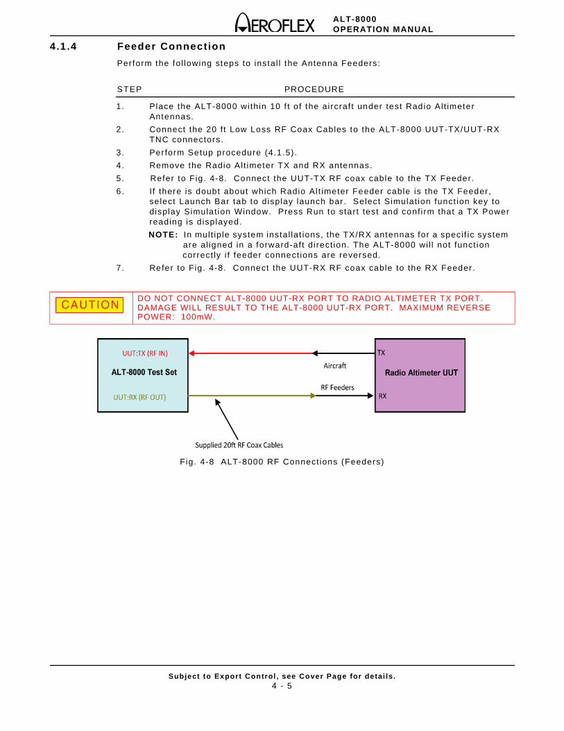
ALT-8000OPERATION MANUAL
Subject to Export Control , see Cover Page for detai ls .4 - 5
4.1.4 Feeder Connection
Perform the fol lowing steps to instal l the Antenna Feeders:
STEP PROCEDURE
1. Place the ALT-8000 within 10 f t o f the aircraf t under test Radio Al t imeter Antennas.
2. Connect the 20 f t Low Loss RF Coax Cables to the ALT-8000 UUT-TX/UUT-RX TNC connectors.
3. Per form Setup procedure (4.1.5).
4. Remove the Radio Al t imeter TX and RX antennas.
5. Refer to Fig . 4-8. Connect the UUT-TX RF coax cable to the TX Feeder.
6. I f there is doubt about which Radio Alt imeter Feeder cable is the TX Feeder, select Launch Bar tab to display launch bar. Select Simulat ion funct ion key to display Simulat ion Window. Press Run to start test and conf i rm that a TX Power reading is displayed.
NOTE: In mult ip le system instal lat ions, the TX/RX antennas for a speci f ic system are al igned in a forward-af t direct ion. The ALT-8000 wi l l not funct ion
correct ly i f feeder connect ions are reversed.
7. Refer to Fig. 4-8. Connect the UUT-RX RF coax cable to the RX Feeder.
Fig. 4-8 ALT-8000 RF Connect ions (Feeders)
DO NOT CONNECT ALT-8000 UUT-RX PORT TO RADIO ALTIMETER TX PORT. DAMAGE WILL RESULT TO THE ALT-8000 UUT-RX PORT. MAXIMUM REVERSE POWER: 100mW.
CAUTION
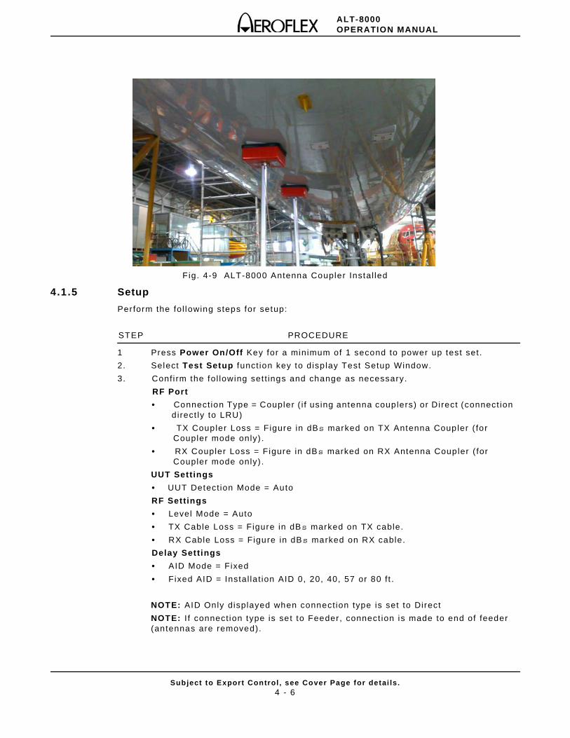
ALT-8000OPERATION MANUAL
Subject to Export Control , see Cover Page for detai ls .4 - 6
Fig. 4-9 ALT-8000 Antenna Coupler Instal led
4.1.5 Setup
Perform the fol lowing steps for setup:
STEP PROCEDURE
1 Press Power On/Off Key for a minimum of 1 second to power up test set .
2. Select Test Setup funct ion key to disp lay Test Setup Window.
3. Conf i rm the fol lowing set t ings and change as necessary.
RF Port
• Connect ion Type = Coupler ( i f using antenna couplers) or Direct (connect ion d irect ly to LRU)
• TX Coupler Loss = Figure in dBs marked on TX Antenna Coupler ( for Coupler mode only) .
• RX Coupler Loss = Figure in dBs marked on RX Antenna Coupler ( for Coupler mode only) .
UUT Settings
• UUT Detect ion Mode = Auto
RF Settings
• Level Mode = Auto
• TX Cable Loss = Figure in dBs marked on TX cable.
• RX Cable Loss = Figure in dBs marked on RX cable.
Delay Settings
• AID Mode = Fixed
• Fixed AID = Instal la t ion AID 0, 20, 40, 57 or 80 f t .
NOTE: AID Only displayed when connect ion type is set to Direct
NOTE: I f connect ion type is set to Feeder, connect ion is made to end of feeder (antennas are removed).
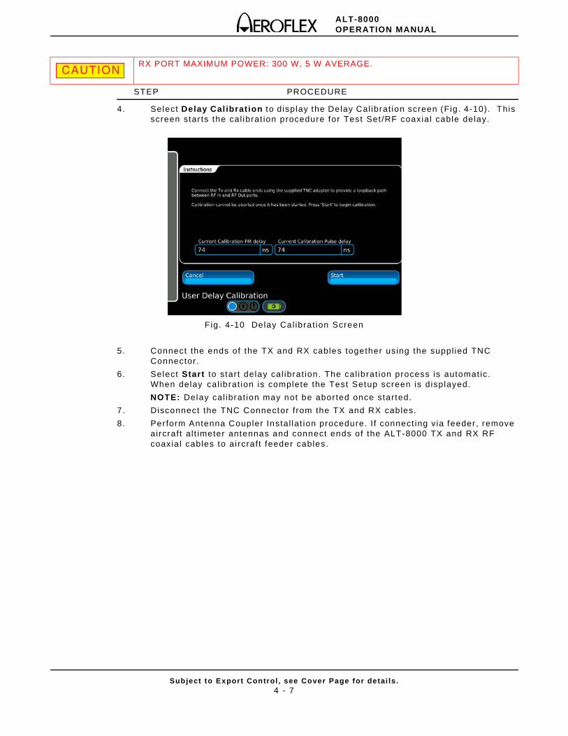
ALT-8000OPERATION MANUAL
Subject to Export Control , see Cover Page for detai ls .4 - 7
STEP PROCEDURE
4. Select Delay Cal ibration to display the Delay Cal ibrat ion screen (Fig . 4-10). This screen star ts the cal ibrat ion procedure for Test Set /RF coaxial cable delay.
Fig. 4-10 Delay Cal ibrat ion Screen
5. Connect the ends of the TX and RX cables together using the suppl ied TNC Connector .
6. Select Start to start delay cal ibrat ion. The cal ibrat ion process is automat ic. When delay cal ibrat ion is complete the Test Setup screen is displayed.
NOTE: Delay cal ibrat ion may not be abor ted once started.
7. Disconnect the TNC Connector f rom the TX and RX cables.
8. Per form Antenna Coupler Instal lat ion procedure. I f connect ing via feeder, remove aircraft al t imeter antennas and connect ends of the ALT-8000 TX and RX RF coaxial cables to ai rcraft feeder cables.
RX PORT MAXIMUM POWER: 300 W, 5 W AVERAGE. CAUTION
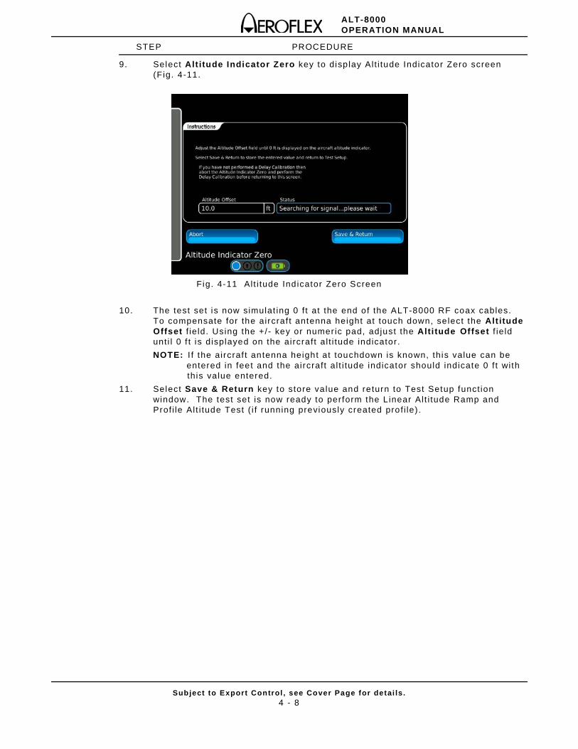
ALT-8000OPERATION MANUAL
Subject to Export Control , see Cover Page for detai ls .4 - 8
STEP PROCEDURE
9. Select Alt itude Indicator Zero key to disp lay Al t i tude Indicator Zero screen (F ig. 4-11.
Fig. 4-11 Al t i tude Ind icator Zero Screen
10. The test set is now simulat ing 0 f t at the end of the ALT-8000 RF coax cables. To compensate for the aircraf t antenna height at touch down, se lect the Alt itude Offset f ie ld. Using the +/ - key or numer ic pad, adjust the Alti tude Offset f ie ld unt i l 0 f t is displayed on the aircraft al t i tude indicator.
NOTE: I f the aircraf t antenna height at touchdown is known, this value can be entered in feet and the aircraft al t i tude indicator should indicate 0 f t wi th
this value entered.
11. Select Save & Return key to store va lue and return to Test Setup funct ion window. The test set is now ready to perform the L inear Al t i tude Ramp and Prof i le Al t i tude Test ( i f running previously created prof i le) .
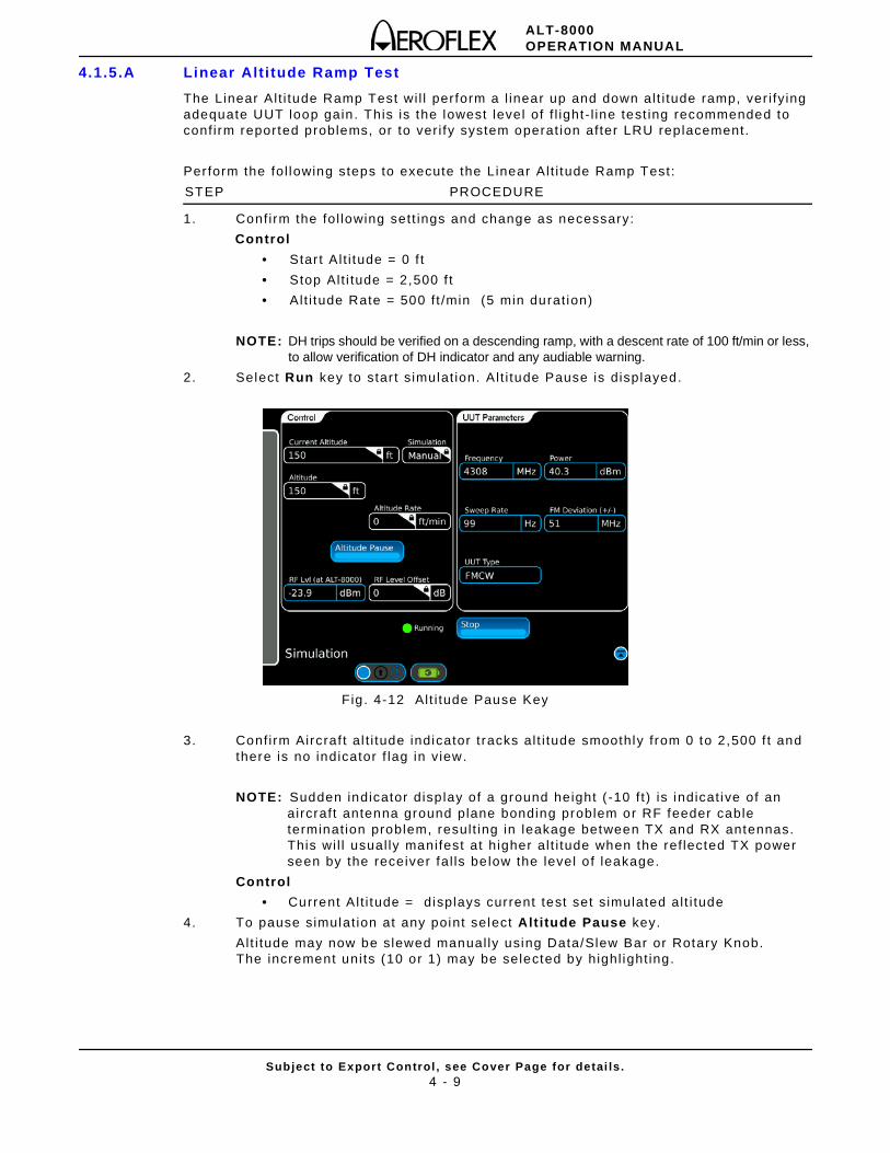
ALT-8000OPERATION MANUAL
Subject to Export Control , see Cover Page for detai ls .4 - 9
4.1.5.A Linear Alt i tude Ramp Test
The Linear Al t i tude Ramp Test wi l l perform a l inear up and down al t i tude ramp, ver i fy ing adequate UUT loop gain. This is the lowest level of f l ight - l ine test ing recommended to conf i rm reported problems, or to ver i fy system operat ion after LRU replacement.
Per form the fol lowing steps to execute the Linear Al t i tude Ramp Test:
STEP PROCEDURE
1. Conf irm the fol lowing sett ings and change as necessary:
Control
• Star t Al t i tude = 0 f t
• Stop Alt i tude = 2,500 f t
• Alt i tude Rate = 500 f t /min (5 min durat ion)
NOTE: DH trips should be verified on a descending ramp, with a descent rate of 100 ft/min or less, to allow verification of DH indicator and any audiable warning.
2. Select Run key to star t s imulat ion. Al t i tude Pause is displayed.
Fig. 4-12 Al t i tude Pause Key
3. Conf irm Aircraf t al t i tude indicator t racks al t i tude smoothly from 0 to 2,500 f t and there is no indicator f lag in v iew.
NOTE: Sudden indicator disp lay of a ground height ( -10 f t ) is indicat ive of an a ircraft antenna ground plane bonding problem or RF feeder cable terminat ion problem, result ing in leakage between TX and RX antennas. This wi l l usual ly manifest at higher al t i tude when the ref lected TX power seen by the receiver fal ls be low the level o f leakage.
Control
• Current Al t i tude = displays current test set s imulated al t i tude
4. To pause simulat ion at any point select Alt itude Pause key.
Al t i tude may now be slewed manual ly using Data/Slew Bar or Rotary Knob. The increment uni ts (10 or 1) may be selected by highl ight ing.
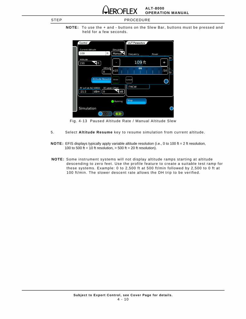
ALT-8000OPERATION MANUAL
Subject to Export Control , see Cover Page for detai ls .4 - 10
STEP PROCEDURE
NOTE: To use the + and - buttons on the Slew Bar, buttons must be pressed and held for a few seconds.
Fig. 4-13 Paused Alt i tude Rate / Manual Al t i tude Slew
5. Select Alt itude Resume key to resume simulat ion from current al t i tude.
NOTE: EFIS displays typically apply variable altitude resolution (i.e., 0 to 100 ft = 2 ft resolution, 100 to 500 ft = 10 ft resolution, > 500 ft = 20 ft resolution).
NOTE: Some inst rument systems wi l l not display al t i tude ramps start ing at al t i tude descending to zero feet . Use the prof i le feature to create a sui table test ramp for these systems. Example: 0 to 2,500 f t at 500 f t /min fol lowed by 2,500 to 0 f t at 100 f t /min. The slower descent rate al lows the DH t r ip to be ver i f ied.
ALT-8000OPERATION MANUAL
Subject to Export Control , see Cover Page for detai ls .4 - 11
4.1.5.B Profile Creation
The Prof i le Al t i tude Test wi l l execute a sequence of l inear al t i tude ramp legs. Together the legs form a prof i le, which can simulate a complete approach/ landing or departure simulat ion. Prof i les are used to test radio a l t imeters coupled with auto-land systems.
Perform the fol lowing steps to setup an example four leg descent prof i le:
STEP PROCEDURE
1. Press Power On/Off key for a minimum of 1 second to power up test set .
2. Select Launch Bar tab to disp lay launch bar . Select Prof i le Setup funct ion key to display Prof i le Setup Window.
3. Select Add key to display Add Leg window.
4. Leg # 1:
Select Start Altitude to display numeric pad and enter Start Al t i tude = 1510 f t , se lect Enter to conf i rm parameter .
Select Stop Alti tude to display numer ic pad and enter Stop Alt i tude = 1500 f t , select Enter to conf i rm parameter.
Select Alt itude Rate to display numeric pad and enter Al t i tude Rate= 60 fpm, select Enter to conf i rm parameter .
Select Enter to conf i rm leg. Leg #1 wi l l now be displayed in the Simulat ion Legs table.
5. Select Add Leg key to display Add Leg window
6. Leg # 2:
Select Start Altitude to display numeric pad and enter Start Al t i tude = 1500 f t , select Enter to conf i rm parameter.
Select Stop Alti tude to display numer ic pad and enter Stop Alt i tude = 1000 f t , select Enter to conf i rm parameter.
Select Alt itude Rate to display numeric pad and enter Al t i tude Rate= 1500 fpm, select Enter to conf i rm parameter.
Select Enter to conf i rm leg. Leg #2 wi l l now be displayed in the Simulat ion Legs table.
7. Select Add Leg key to display Add Leg window.
8. Leg # 3:
Select Start Altitude to display numeric pad and enter Start Al t i tude = 1000 f t , select Enter to conf i rm parameter.
Select Stop Alti tude to display numer ic pad and enter Stop Alt i tude = 10 f t , select Enter to conf i rm parameter.
Select Alt itude Rate to display numeric pad and enter Al t i tude Rate= 2970 fpm, select Enter to conf i rm parameter.
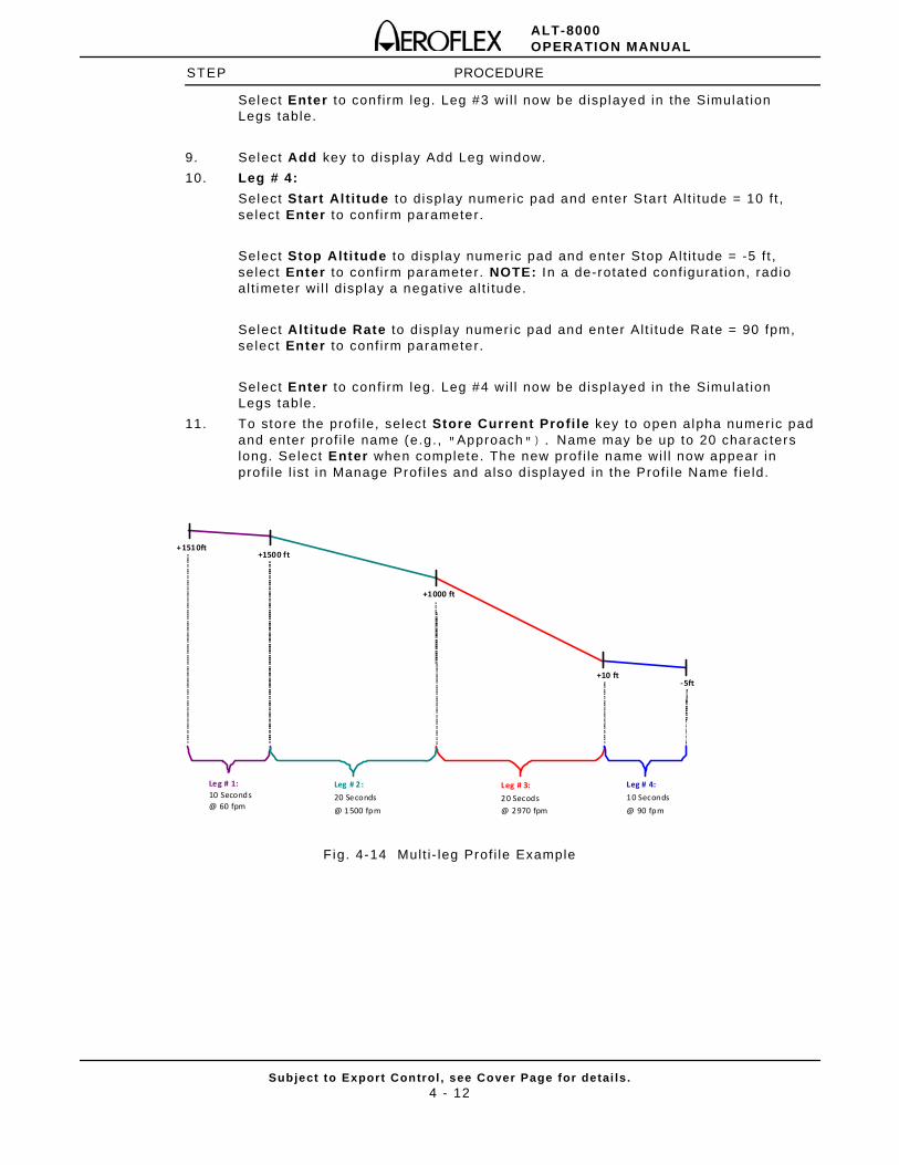
ALT-8000OPERATION MANUAL
Subject to Export Control , see Cover Page for detai ls .4 - 12
STEP PROCEDURE
Select Enter to conf i rm leg. Leg #3 wi l l now be displayed in the Simulat ion Legs table.
9. Select Add key to display Add Leg window.
10. Leg # 4:
Select Start Altitude to display numeric pad and enter Start Al t i tude = 10 f t , select Enter to conf i rm parameter.
Select Stop Alti tude to display numer ic pad and enter Stop Alt i tude = -5 f t , select Enter to conf i rm parameter. NOTE: In a de-rotated conf igurat ion, radio al t imeter wi l l d isplay a negat ive al t i tude.
Select Alt itude Rate to display numeric pad and enter Al t i tude Rate = 90 fpm, select Enter to conf i rm parameter.
Select Enter to conf i rm leg. Leg #4 wi l l now be displayed in the Simulat ion Legs table.
11. To store the prof i le, select Store Current Profi le key to open alpha numeric pad and enter prof i le name (e.g., "Approach"). Name may be up to 20 characters long. Select Enter when complete. The new prof i le name wi l l now appear in prof i le l ist in Manage Prof i les and also d isplayed in the Prof i le Name f ie ld.
Fig. 4-14 Mult i - leg Prof i le Example
-5ft +10 ft
+1000 ft
+1500 ft +1510ft
Leg # 4: 10 Seconds @ 90 fpm
Leg # 3: 20 Secods @ 2970 fpm
Leg # 2 : 20 Seconds @ 1 500 fpm
Leg # 1: 10 Seconds @ 60 fpm
ALT-8000OPERATION MANUAL
Subject to Export Control , see Cover Page for detai ls .4 - 13
4.1.5.C Profile Alt itude Test
Per form the fol lowing steps to setup a Prof i le Al t i tude Test:
STEP PROCEDURE
1. Perform the Setup procedure (4.1.5).
2. Select Launch Bar tab to display launch bar. Select Profile Setup funct ion key to display Prof i le Setup window.
3. Select Recal l Profi le key to display Load Prof i le window. Select desired prof i le l isted in prof i le table and select Recal l . Recal led prof i le wi l l now be resident in memory and ready for execut ion.
4. Select Launch Bar tab to display launch bar . Select Simulation funct ion key to display Radio Al t imeter Funct ion Test Window.
5. Conf irm the fol lowing sett ing and change as necessary:
• Control Simulat ion = Prof i le
6. Select Run key to star t s imulat ion.
7. The Star t Al t i tude, Stop Alt i tude and Al t i tude Rate wi l l be displayed for the current leg. Current Al t i tude is also displayed.
8. To view the overal l progress of the prof i le execut ion, the Prof i le Setup funct ion window displays a graphical plot of the simulated al t i tude versus t ime.
ALT-8000OPERATION MANUAL
Subject to Export Control , see Cover Page for detai ls .4 - 14
4.1.5.D UUT Parametric Tests
Although the Auto RF Level mode ensures that loop gain is ver i f ied and system in tegr i ty is ver i f ied, there are t imes when i t is desirable to review the parametr ic per formance of an LRU, part icu lar ly when intermit tent problems have been reported.
NOTE: Manufacturers speci f icat ions should always be referred to .
LRU Review Guidelines
Frequency: Var ies between LRRA models. Typica l ly centered at 4.3 GHz +/ -70 MHz.
FM Deviat ion: Var ies between LRRA models. FM/CW types typ ical ly 100 to 140 MHz.
Sweep Rate: Var ies between LRRA models. FM/CW types typica l ly 50 to 160 Hz.
NOTE: In a dual or t r ip le LRRA instal lat ion, each LRU may have a di f ferent sweep rate set, to avoid cross channel interference.
Power: Var ies between LRRA models. FM/CW types typical ly 150 mW to 1 W.
NOTE: Manufacturers power speci f icat ions are stated at the LRU, so expect lower power levels to be measured at the Aircraft Antenna.
NOTE: Typical Aircraft Antenna gains are 10 dBi ( radiated) . Because the ALT-8000 antenna couplers couple in the near f ie ld of the antenna, th is gain wi l l not be real ized.
In cases where a Linear Al t i tude Ramp Test has been performed, wi th RF Level set to Auto and a tracking fai lure occurs ( i .e. , indicator f lag in view) a power measurement can be made to determine i f the problem is in the TX path and where in the TX path.
Possible TX Path Problems
• LRU TX Power low
• RF Feeder cable a. Excessive loss or bad VSWR due to coax cable water ingress. b. Bad connector Terminat ion
• TX Antenna Bad a. Mechanical damage b. Lightn ing st r ike c. Corrosion due to water ingress
If a power test at the a ircraft antenna is sat isfactory, the RX path should be invest igated.
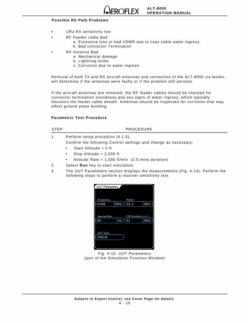
ALT-8000OPERATION MANUAL
Subject to Export Control , see Cover Page for detai ls .4 - 15
Possible RX Path Problems
• LRU RX sensi t ivi ty low
• RF Feeder cable Bad a. Excessive loss or bad VSWR due to coax cable water ingress. b . Bad connector Terminat ion
• RX Antenna Bad a. Mechanical damage b. Lightn ing st r ike c. Corrosion due to water ingress
Removal of both TX and RX a ircraft antennas and connect ion of the ALT-8000 via feeder, wi l l determine i f the antennas were faul ty or i f the problem st i l l persists.
I f the aircraft antennas are removed, the RF feeder cables should be checked for connector terminat ion soundness and any signs of water ingress, which typical ly discolors the feeder cable sheath. Antennas should be inspected for corrosion that may effect ground plane bonding.
Parametric Test Procedure
STEP PROCEDURE
1. Perform setup procedure (4 .1.5).
Conf irm the fol lowing Contro l sett ings and change as necessary:
• Star t Al t i tude = 0 f t
• Stop Alt i tude = 2,500 f t
• Alt i tude Rate = 1,000 f t /min (2.5 mins durat ion)
2. Select Run key to star t s imulat ion.
3. The UUT Parameters sect ion displays the measurements (F ig. 4-14). Perform the fol lowing steps to perform a receiver sensi t iv i ty test .
Fig. 4-15 UUT Parameters(par t of the Simulat ion Funct ion Window)
ALT-8000OPERATION MANUAL
Subject to Export Control , see Cover Page for detai ls .4 - 16
Receiver Sensitiv ity Test Procedure
STEP PROCEDURE
1. Perform setup procedure (4 .1.5).
2. Select Launch Bar tab to display launch bar . Select Test Setup funct ion key to display Test Setup Window.
• RF Set t ings Level Mode = Manual
3. Select Launch Bar tab to display launch bar . Simulat ion funct ion key to display Radio Al t imeter Funct ion Test Window.
4. Conf irm the fol lowing sett ing and change as necessary:
• Start Al t i tude = 2,500 f t
• Alt i tude Rate = 0 f t /min
5. Select Run key to star t s imulat ion.
6. Select RF Level , observe Alt i tude Indicator and decrement RF Level unt i l Indicator f lags. The RF Level sett ing represents the insta l led receiver sensi t iv i ty.
NOTE: LRRA LRUs typical ly reduce the ir receiver sensi t iv i ty as al t i tude decreases to avoid false locks. Test ing at typical ly 2,500 f t a l t i tude should ensure that maximum receiver sensi t iv i ty is measured.
ALT-8000OPERATION MANUAL
Subject to Export Control , see Cover Page for detai ls .5 - 1
Chapter 5 - Maintenance
5.1 INTRODUCTION
5.1.1 Visual Inspections
Visual inspect ions should be performed per iodical ly depending on operat ing envi ronment , maintenance and use.
5.1.2 External Cleaning
STEP PROCEDURESTEP PROCEDURE
1. Clean f ront panel but tons and disp lay face with soft l int- f ree cloth. I f d ir t is di f f icul t to remove, dampen cloth with water and a mi ld l iqu id detergent.
2. Remove grease, fungus and ground-in dir t f rom sur faces with soft l int - f ree cloth dampened (not soaked) with isopropyl alcohol.
3. Remove dust and dir t f rom connectors with sof t-br ist led brush.
4. Cover connectors, not in use, with sui table dust cover to prevent tarnishing of connector contacts.
5. Clean cables with soft l int- f ree cloth.
6. Paint exposed metal surface to avoid corrosion.
5.2 MAINTENANCE PROCEDURES
5.2.1 Battery Replacement
Perform the fol lowing steps to replace bat tery:
STEP PROCEDURESTEP PROCEDURE
1. Ver i fy the ALT-8000 is OFF and not connected to AC power via the AC Adaptor.
2. Place the ALT-8000 on a f lat surface, lower side up.
3. Li f t the bat tery cover Pul l Tab to a ver t ical posi t ion to release the Battery Cover and l i f t away from the Case Assembly.
4. Remove the bat tery from the battery housing (Fig . 5-1).
5. Instal l new battery in the battery housing.
6. Replace the battery cover on the case assembly by locat ing the l ipped end of the cover in the case assembly. Li f t the pul l tab and push the battery cover down, ensur ing the catch engages. Release the pul l tab and ensure bat tery lays f lat inside the recess.
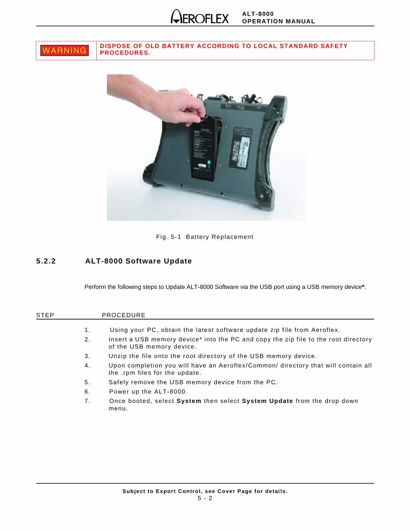
ALT-8000OPERATION MANUAL
Subject to Export Control , see Cover Page for detai ls .5 - 2
Fig. 5-1 Bat tery Replacement
5.2.2 ALT-8000 Software Update
Perform the following steps to Update ALT-8000 Software via the USB port using a USB memory device*:
STEP PROCEDURE
1. Using your PC, obtain the latest sof tware update zip f i le f rom Aerof lex.
2. Inser t a USB memory device* into the PC and copy the zip f i le to the root di rectory of the USB memory device.
3. Unzip the f i le onto the root d irectory o f the USB memory device.
4. Upon complet ion you wi l l have an Aerof lex/Common/ d irectory that wi l l contain al l the .rpm f i les for the update.
5. Safely remove the USB memory device from the PC.
6. Power up the ALT-8000.
7. Once booted, select System then select System Update f rom the drop down menu.
DISPOSE OF OLD BATTERY ACCORDING TO LOCAL STANDARD SAFETY PROCEDURES.WARNINGWARNING
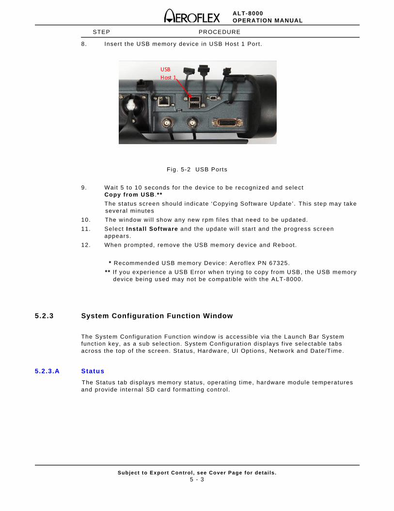
ALT-8000OPERATION MANUAL
Subject to Export Control , see Cover Page for detai ls .5 - 3
STEP PROCEDURE
8. Inser t the USB memory device in USB Host 1 Port .
Fig . 5-2 USB Ports
9. Wait 5 to 10 seconds for the device to be recognized and select Copy from USB .**
The status screen should ind icate ‘Copying Software Update’ . This step may take several minutes
10. The window wi l l show any new rpm f i les that need to be updated.
11. Select Install Software and the update wi l l start and the progress screen appears.
12. When prompted, remove the USB memory device and Reboot.
* Recommended USB memory Device: Aerof lex PN 67325.
** I f you exper ience a USB Error when try ing to copy f rom USB, the USB memory device being used may not be compatible wi th the ALT-8000.
5.2.3 System Configuration Function Window
The System Configurat ion Funct ion window is accessible via the Launch Bar System funct ion key, as a sub se lect ion. System Conf igurat ion d isplays f ive selectable tabs across the top of the screen. Status, Hardware, UI Opt ions, Network and Date/Time.
5.2.3.A Status
The Status tab displays memory status, operat ing t ime, hardware module temperatures and provide internal SD card formatt ing control .
USB Host 1
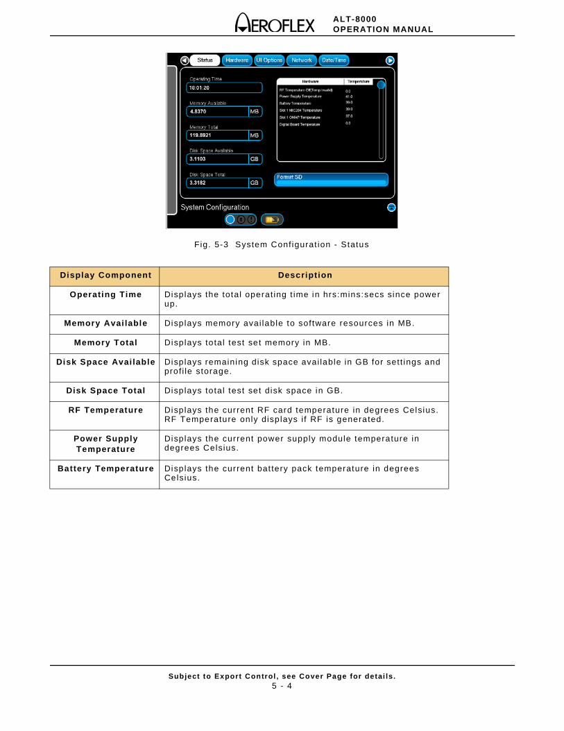
ALT-8000OPERATION MANUAL
Subject to Export Control , see Cover Page for detai ls .5 - 4
Fig. 5-3 System Conf igurat ion - Status
Display Component Description
Operating Time Displays the total operat ing t ime in hrs:mins:secs since power up.
Memory Avai lable Displays memory avai lable to software resources in MB.
Memory Total Displays to tal test set memory in MB.
Disk Space Avai lable Displays remaining disk space avai lable in GB for sett ings and prof i le storage.
Disk Space Total Displays to tal test set disk space in GB.
RF Temperature Displays the current RF card temperature in degrees Celsius. RF Temperature only disp lays i f RF is generated.
Power Supply Temperature
Displays the current power supply module temperature in degrees Celsius.
Battery Temperature Displays the current bat tery pack temperature in degrees Celsius.
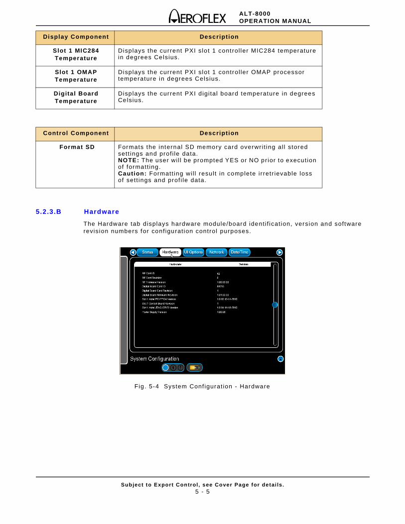
ALT-8000OPERATION MANUAL
Subject to Export Control , see Cover Page for detai ls .5 - 5
5.2.3.B Hardware
The Hardware tab displays hardware module/board ident i f icat ion, version and software revis ion numbers for conf igurat ion control purposes.
Fig . 5-4 System Conf igurat ion - Hardware
Display Component Description
Slot 1 MIC284 Temperature
Displays the current PXI slo t 1 control ler MIC284 temperature in degrees Celsius.
Slot 1 OMAP Temperature
Displays the current PXI slot 1 control ler OMAP processor temperature in degrees Celsius.
Digital Board Temperature
Displays the current PXI d igi tal board temperature in degrees Celsius.
Control Component Description
Format SD Formats the internal SD memory card overwr i t ing al l stored sett ings and prof i le data.NOTE: The user wi l l be prompted YES or NO prior to execut ion of formatt ing.Caution: Formatt ing wi l l resul t in complete i r retr ievable loss of sett ings and prof i le data.
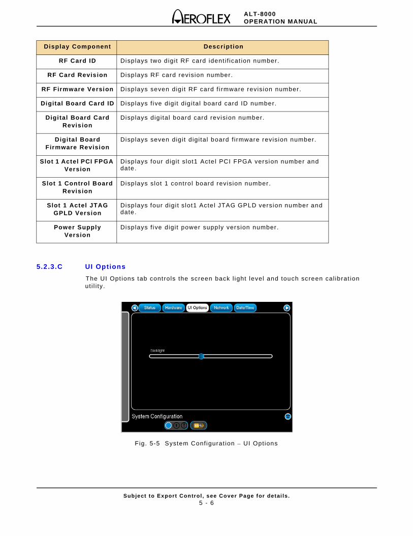
ALT-8000OPERATION MANUAL
Subject to Export Control , see Cover Page for detai ls .5 - 6
5.2.3.C UI Options
The UI Opt ions tab controls the screen back l ight level and touch screen cal ibrat ion ut i l i ty.
Fig. 5-5 System Conf igurat ion – UI Options
Display Component Description
RF Card ID Displays two d igi t RF card ident i f icat ion number.
RF Card Revision Displays RF card revis ion number.
RF Firmware Version Displays seven digi t RF card f i rmware revis ion number.
Digital Board Card ID Displays f ive digi t dig i tal board card ID number.
Digital Board Card Revision
Displays dig i tal board card revision number.
Digital Board Firmware Revision
Displays seven digi t d igi tal board f i rmware revis ion number.
Slot 1 Actel PCI FPGA Version
Displays four d igi t s lot1 Acte l PCI FPGA version number and date.
Slot 1 Control Board Revision
Displays slot 1 contro l board revis ion number.
Slot 1 Actel JTAG GPLD Version
Displays four digi t s lot1 Acte l JTAG GPLD version number and date.
Power Supply Version
Displays f ive digi t power supply version number.
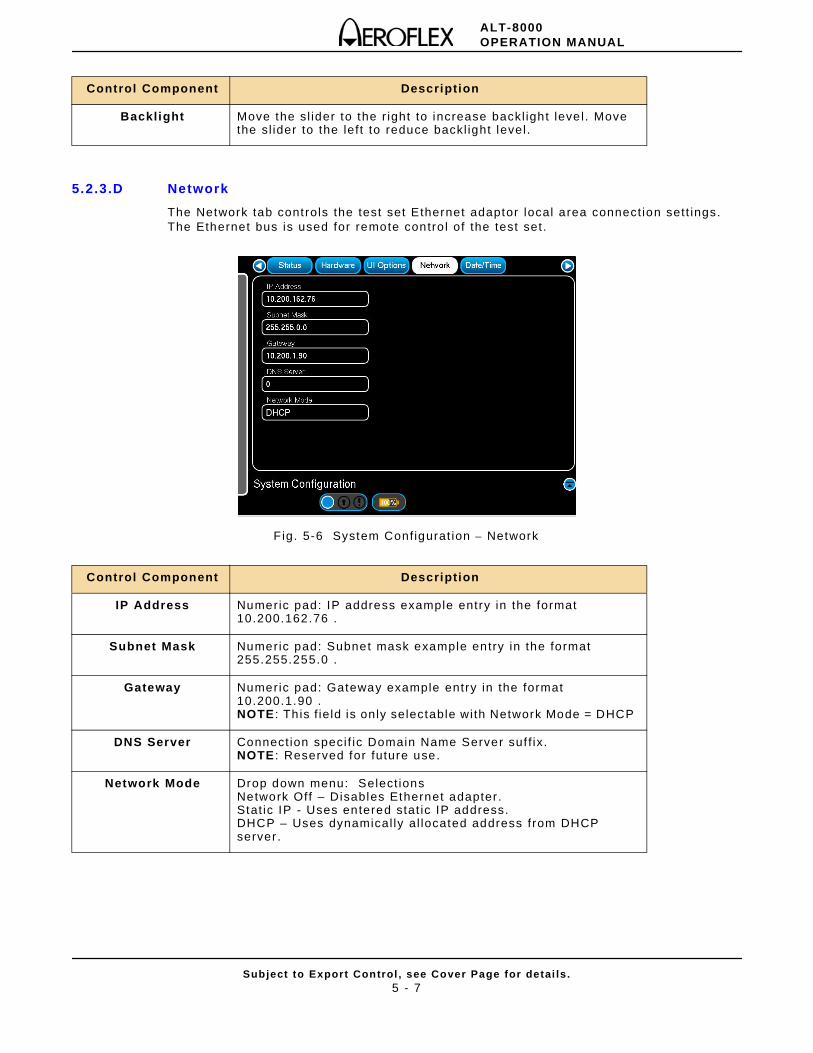
ALT-8000OPERATION MANUAL
Subject to Export Control , see Cover Page for detai ls .5 - 7
5.2.3.D Network
The Network tab controls the test set Ethernet adaptor local area connect ion sett ings. The Ethernet bus is used for remote contro l of the test set.
F ig. 5-6 System Conf igurat ion – Network
Control Component Description
Backlight Move the sl ider to the r ight to increase backl ight leve l . Move the sl ider to the lef t to reduce backl ight level .
Control Component Description
IP Address Numeric pad: IP address example entry in the format 10.200.162.76 .
Subnet Mask Numeric pad: Subnet mask example entry in the format 255.255.255.0 .
Gateway Numeric pad: Gateway example entry in the format 10.200.1.90 . NOTE : Th is f ie ld is only selectable with Network Mode = DHCP
DNS Server Connect ion speci f ic Domain Name Server suf f ix. NOTE : Reserved for future use.
Network Mode Drop down menu: Select ions Network Off – Disables Ethernet adapter . Stat ic IP - Uses entered stat ic IP address.DHCP – Uses dynamical ly al located address from DHCP server .
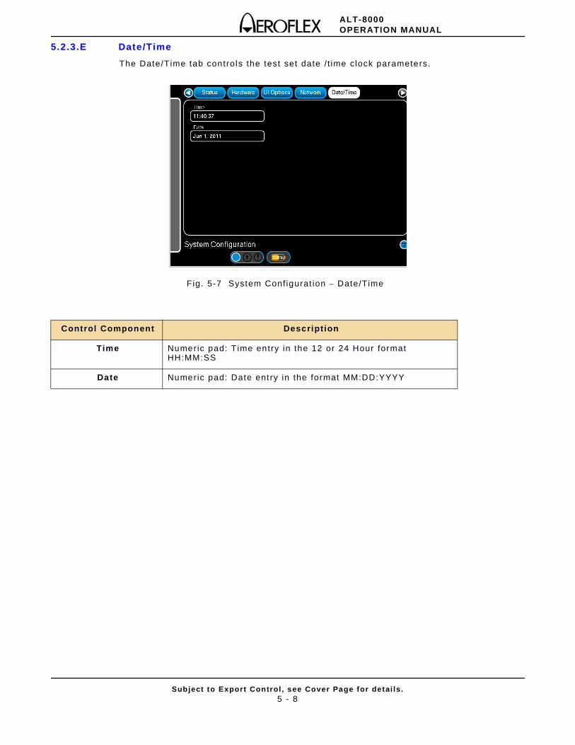
ALT-8000OPERATION MANUAL
Subject to Export Control , see Cover Page for detai ls .5 - 8
5.2.3.E Date/Time
The Date/Time tab controls the test set date / t ime clock parameters.
Fig. 5-7 System Conf igurat ion – Date/Time
Control Component Description
Time Numeric pad: T ime entry in the 12 or 24 Hour format HH:MM:SS
Date Numeric pad: Date entry in the format MM:DD:YYYY
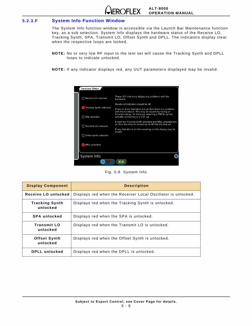
ALT-8000OPERATION MANUAL
Subject to Export Control , see Cover Page for detai ls .5 - 9
5.2.3.F System Info Function Window
The System Info funct ion window is accessible via the Launch Bar Maintenance funct ion key, as a sub select ion. System Info displays the hardware sta tus of the Receive LO, Tracking Synth, SPA, Transmit LO, Offset Synth and DPLL. The ind icators display clear when the respect ive loops are locked.
NOTE: No or very low RF input to the test set wi l l cause the Tracking Synth and DPLL loops to indicate unlocked.
NOTE: I f any ind icator displays red, any UUT parameters displayed may be inval id.
Fig. 5-8 System Info
Display Component Description
Receive LO unlocked Displays red when the Receiver Local Osci l lator is unlocked.
Tracking Synth unlocked
Displays red when the Tracking Synth is unlocked.
SPA unlocked Displays red when the SPA is unlocked.
Transmit LO unlocked
Displays red when the Transmit LO is unlocked.
Offset Synth unlocked
Displays red when the Offset Synth is un locked.
DPLL unlocked Displays red when the DPLL is unlocked.
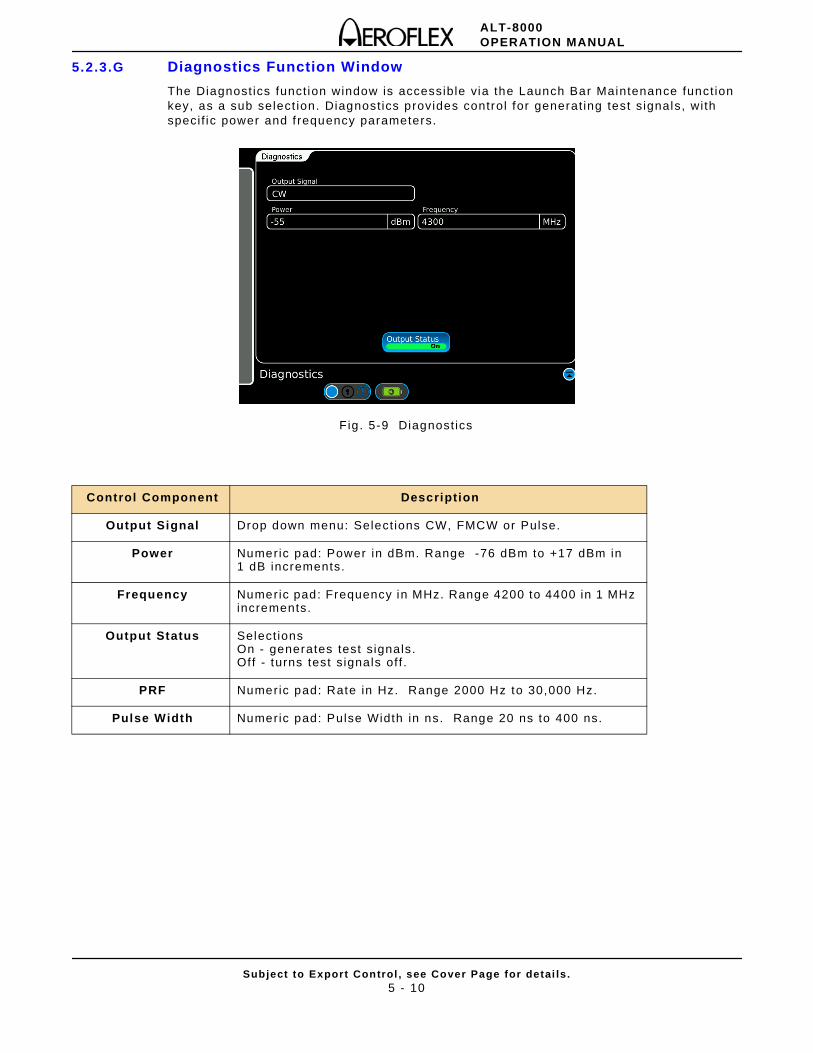
ALT-8000OPERATION MANUAL
Subject to Export Control , see Cover Page for detai ls .5 - 10
5.2.3.G Diagnostics Function Window
The Diagnost ics funct ion window is accessible via the Launch Bar Maintenance funct ion key, as a sub select ion. Diagnost ics provides control for generat ing test s ignals, wi th speci f ic power and f requency parameters.
Fig . 5-9 Diagnost ics
Control Component Description
Output Signal Drop down menu: Select ions CW, FMCW or Pulse.
Power Numeric pad: Power in dBm. Range -76 dBm to +17 dBm in 1 dB increments.
Frequency Numeric pad: Frequency in MHz. Range 4200 to 4400 in 1 MHz increments.
Output Status Select ionsOn - generates test s ignals. Off - turns test s ignals of f .
PRF Numeric pad: Rate in Hz. Range 2000 Hz to 30,000 Hz.
Pulse Width Numeric pad: Pulse Width in ns. Range 20 ns to 400 ns.
ALT-8000OPERATION MANUAL
Subject to Export Control , see Cover Page for detai ls .6 - 1
Chapter 6 - Principles of Operation
6.1 PRINCIPLES OF OPERATION
6.1.1 ALT-8000 Test Operation
FMCW Radio Altimeters
The ALT-8000 Test-Set analyzes the transmit ted signal f rom a FMCW radio a l t imeter to der ive i ts waveform parameters. Test-set calculates the required adjustment on received signal based on user inputs and dig i tal ly generates the echo signal to test the DUT response in mult ip le aspects.
For convent ional FMCW signal, the Test-Set dynamical ly adds an adjustable frequency offset to the received signal and then generates the echo signal wi th a control led power level .
For constant f requency di f ference FMCW signal, the Test-Set uni formly adds an adjustable f requency of fset to the received signal and then generates the echo signal wi th a control led power level .
Pulse Radio Alt imeters
The ALT-8000 Test-Set analyzes the transmi t ted signal f rom a FMCW radio al t imeter to der ive i ts waveform parameters. Test-set calcula tes the required t ime delay based on user inputs and digi tal ly controls the t ime and power level of echo pulses to be transmit ted to the DUT.
6.1.2 Assemblies
Control Panel Assembly
The Control Panel Assembly provides On/Off , Home But tons and Status LEDs.
Power Supply Assembly
The Power Supply Assembly provides power for module operat ion and +5 Volt bias for appl ied power status.
RF RX-TX Assembly
The RF RX-TX Assembly measures the Test Set ’s RF input s ignal to obtain DUT waveform parameters, and generates RF output s ignal wi th required adjustment. The Assembly connects to the Digi tal RadAlt Assembly using a 40-wi re r ibbon cable for power supply and data input/output .
PXI Backplane Assembly
The PXI Backplane Assembly routes elect r ical s ignals between the var ious system assembl ies.
Rear Panel Assembly
The Rear Panel Assembly provides access to the Tests Set ’s Input/Output connectors and AC charger.
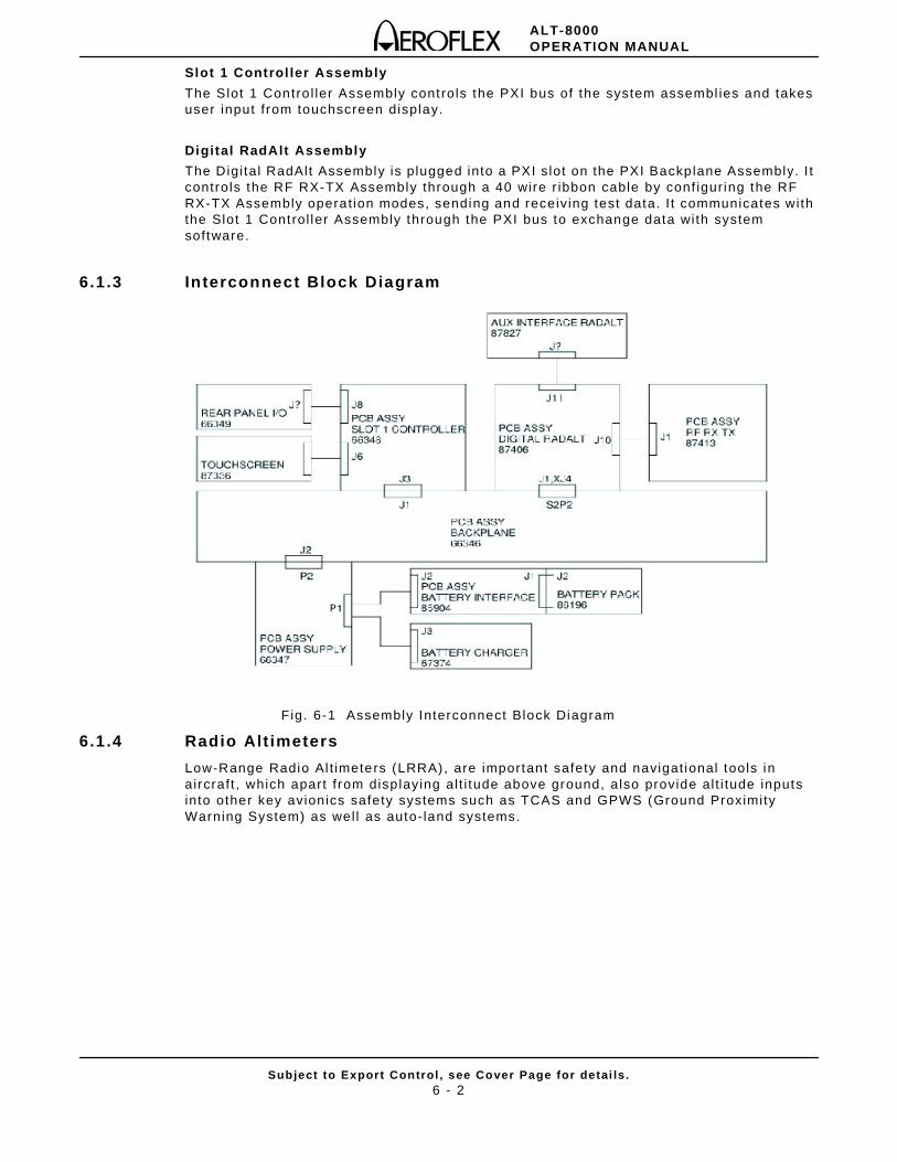
ALT-8000OPERATION MANUAL
Subject to Export Control , see Cover Page for detai ls .6 - 2
Slot 1 Control ler Assembly
The Slot 1 Contro l ler Assembly controls the PXI bus of the system assembl ies and takes user input f rom touchscreen display.
Digital RadAlt Assembly
The Digi tal RadAlt Assembly is plugged into a PXI slot on the PXI Backplane Assembly. I t controls the RF RX-TX Assembly through a 40 wire r ibbon cable by conf igur ing the RF RX-TX Assembly operat ion modes, sending and receiving test data. I t communicates with the Slot 1 Control ler Assembly through the PXI bus to exchange data with system software.
6.1.3 Interconnect Block Diagram
Fig. 6-1 Assembly Interconnect Block Diagram
6.1.4 Radio Alt imeters
Low-Range Radio Al t imeters (LRRA), are important safety and navigat ional tools in aircraft , which apart f rom disp laying al t i tude above ground, also provide al t i tude inputs into other key avionics safety systems such as TCAS and GPWS (Ground Proximity Warning System) as wel l as auto-land systems.
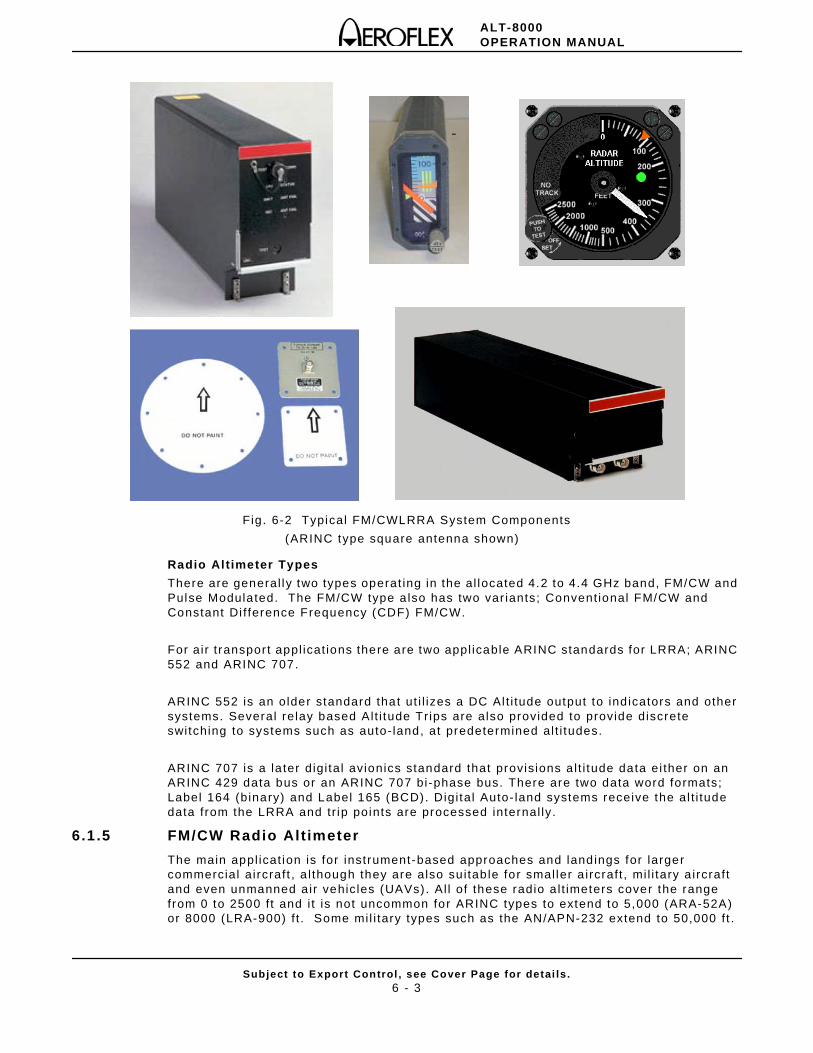
ALT-8000OPERATION MANUAL
Subject to Export Control , see Cover Page for detai ls .6 - 3
Fig. 6-2 Typical FM/CWLRRA System Components
(ARINC type square antenna shown)
Radio Altimeter Types
There are general ly two types operat ing in the al located 4.2 to 4.4 GHz band, FM/CW and Pulse Modulated. The FM/CW type a lso has two var iants; Convent ional FM/CW and Constant Di f ference Frequency (CDF) FM/CW.
For air t ransport appl icat ions there are two appl icable ARINC standards for LRRA; ARINC 552 and ARINC 707.
ARINC 552 is an older standard that ut i l izes a DC Al t i tude output to ind icators and other systems. Several relay based Alt i tude Trips are also provided to provide discrete switching to systems such as auto-land, at predetermined al t i tudes.
ARINC 707 is a la ter digi tal avionics standard that provisions a l t i tude data ei ther on an ARINC 429 data bus or an ARINC 707 bi-phase bus. There are two data word formats; Label 164 (binary) and Label 165 (BCD). Digi tal Auto- land systems receive the al t i tude data from the LRRA and tr ip points are processed internal ly.
6.1.5 FM/CW Radio Alt imeter
The main appl icat ion is for instrument-based approaches and landings for larger commercial aircraft , a l though they are also sui tab le for smal ler a ircraft , mi l i tary a ircraft and even unmanned a ir vehicles (UAVs). Al l of these radio a l t imeters cover the range from 0 to 2500 f t and i t is not uncommon for ARINC types to extend to 5,000 (ARA-52A) or 8000 (LRA-900) f t . Some mil i tary types such as the AN/APN-232 extend to 50,000 f t .
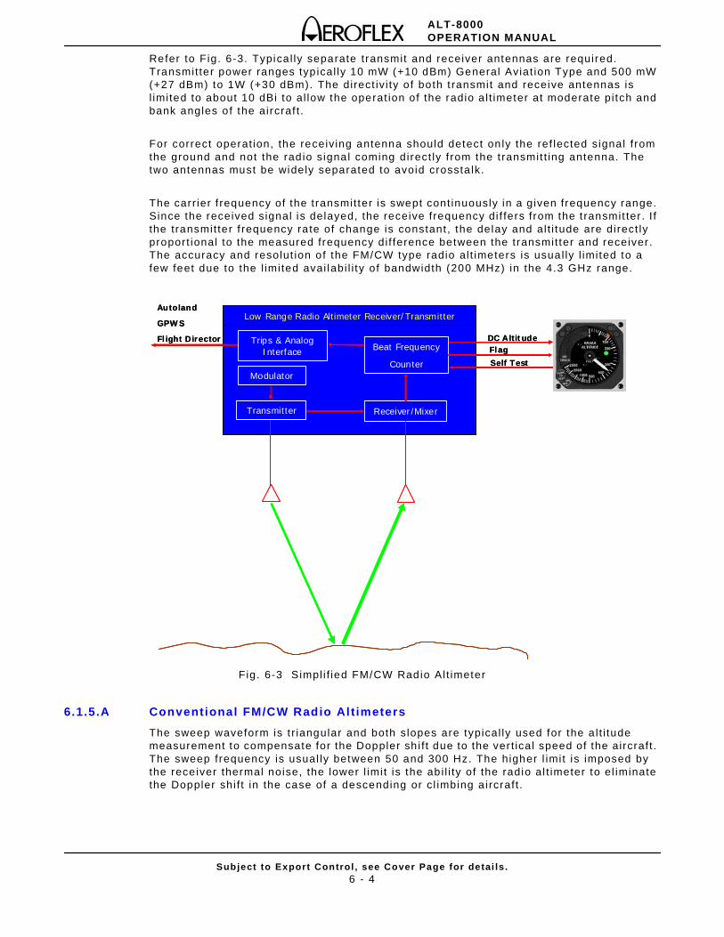
ALT-8000OPERATION MANUAL
Subject to Export Control , see Cover Page for detai ls .6 - 4
Refer to Fig. 6-3. Typica l ly separate transmit and receiver antennas are required. Transmit ter power ranges typ ical ly 10 mW (+10 dBm) General Aviat ion Type and 500 mW (+27 dBm) to 1W (+30 dBm). The direct iv i ty o f both t ransmit and receive antennas is l imited to about 10 dBi to al low the operat ion of the radio a l t imeter at moderate pi tch and bank angles of the aircraf t .
For correct operat ion, the receiving antenna should detect on ly the ref lected signal f rom the ground and not the rad io signal coming direct ly f rom the t ransmit t ing antenna. The two antennas must be widely separated to avoid crossta lk.
The carr ier f requency of the transmit ter is swept cont inuously in a given frequency range. Since the received signal is delayed, the receive frequency di f fers from the t ransmit ter . I f the transmit ter f requency rate of change is constant , the delay and al t i tude are direct ly proport ional to the measured frequency di f ference between the transmit ter and receiver . The accuracy and resolut ion of the FM/CW type radio al t imeters is usual ly l imited to a few feet due to the l imited avai labi l i ty of bandwidth (200 MHz) in the 4.3 GHz range.
Fig. 6-3 Simpl i f ied FM/CW Radio Al t imeter
6.1.5.A Conventional FM/CW Radio Alt imeters
The sweep waveform is t r iangular and both slopes are typical ly used for the a l t i tude measurement to compensate for the Doppler sh i f t due to the ver t ical speed of the aircraft . The sweep frequency is usual ly between 50 and 300 Hz. The higher l imit is imposed by the receiver thermal noise, the lower l imit is the ab i l i ty of the radio al t imeter to el iminate the Doppler shi f t in the case of a descending or c l imbing a ircraft .
Low Range Radio Altimeter Receiver/Transmitter
Modulator
Transmitter
Beat Frequency
Counter
Receiver/Mixer
Trips & AnalogInterface
DC A ltitudeFlagSelf Test
Autoland
GPWS
Flight Director
Low Range Radio Altimeter Receiver/Transmitter
Modulator
Transmitter
Beat Frequency
Counter
Receiver/Mixer
Trips & AnalogInterface
DC A ltitudeFlagSelf Test
Autoland
GPWS
Flight Director
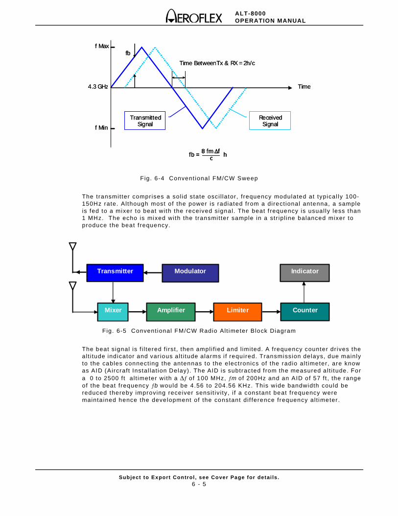
ALT-8000OPERATION MANUAL
Subject to Export Control , see Cover Page for detai ls .6 - 5
Fig. 6-4 Convent ional FM/CW Sweep
The transmit ter compr ises a sol id state osci l lator, f requency modulated at typical ly 100-150Hz rate. Al though most of the power is radiated from a direct ional antenna, a sample is fed to a mixer to beat with the received signal. The beat f requency is usual ly less than 1 MHz. The echo is mixed with the transmi t ter sample in a str ip l ine balanced mixer to produce the beat f requency.
Fig. 6-5 Convent ional FM/CW Radio Alt imeter Block Diagram
The beat s ignal is f i l tered f i rst , then ampl i f ied and l imited. A f requency counter dr ives the al t i tude ind icator and var ious al t i tude alarms i f required. Transmission delays, due mainly to the cables connect ing the antennas to the elect ronics of the radio al t imeter, are know as AID (Aircraft Instal lat ion Delay) . The AID is subtracted f rom the measured a l t i tude. For a 0 to 2500 f t a l t imeter with a Δƒ of 100 MHz, ƒm of 200Hz and an AID of 57 f t , the range of the beat f requency ƒb would be 4.56 to 204.56 KHz. This wide bandwidth could be reduced thereby improving receiver sensi t iv i ty, i f a constant beat f requency were mainta ined hence the development of the constant di f ference frequency al t imeter .
f Max
f Min
Time4.3 GHz
fb
Time Between Tx & RX =2h/c
8 fm Δf c hfb =
f Max
f Min
Time4.3 GHz
SignalTransmittedTransmitted
SignalReceived Signal
Received Signal
fb
Time Between Tx & RX =2h/c
8 fm Δf c hfb = 8 fm Δf c hfb =
Transmitter Modulator
Mixer Amplifier Limiter Counter
Indicator
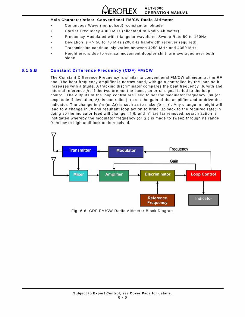
ALT-8000OPERATION MANUAL
Subject to Export Control , see Cover Page for detai ls .6 - 6
Main Characterist ics: Conventional FM/CW Radio Altimeter
• Continuous Wave (not pulsed), constant ampl i tude
• Carr ier Frequency 4300 MHz (al located to Radio Al t imeter)
• Frequency Modulated with t r iangular waveform, Sweep Rate 50 to 160Hz
• Deviat ion is +/ - 50 to 70 MHz (200KHz bandwidth receiver required)
• Transmission cont inuously var ies between 4250 MHz and 4350 MHz
• Height errors due to ver t ical movement doppler shi f t , are averaged over both slope.
6.1.5.B Constant Difference Frequency (CDF) FM/CW
The Constant Dif ference Frequency is s imi lar to convent ional FM/CW alt imeter at the RF end. The beat f requency ampl i f ier is narrow band, with gain contro l led by the loop so i t increases with al t i tude. A t racking d iscr iminator compares the beat f requency ƒb. wi th and internal reference ƒr . I f the two are not the same, an error s ignal is fed to the loop control . The outputs of the loop control are used to set the modulator f requency, ƒm (or ampl i tude i f devia t ion, Δƒ, is contro l led) , to set the gain of the ampl i f ier and to dr ive the indicator. The change in ƒm (or Δƒ) is such as to make ƒb = ƒr . Any change in height wi l l lead to a change in ƒb and resultant loop act ion to br ing ƒb back to the required rate; in doing so the ind icator feed wi l l change. I f ƒb and ƒr are far removed, search act ion is inst igated whereby the modulator f requency (or Δƒ) is made to sweep through i ts range from low to high unt i l lock on is received.
Fig. 6-6 CDF FM/CW Radio Al t imeter Block Diagram
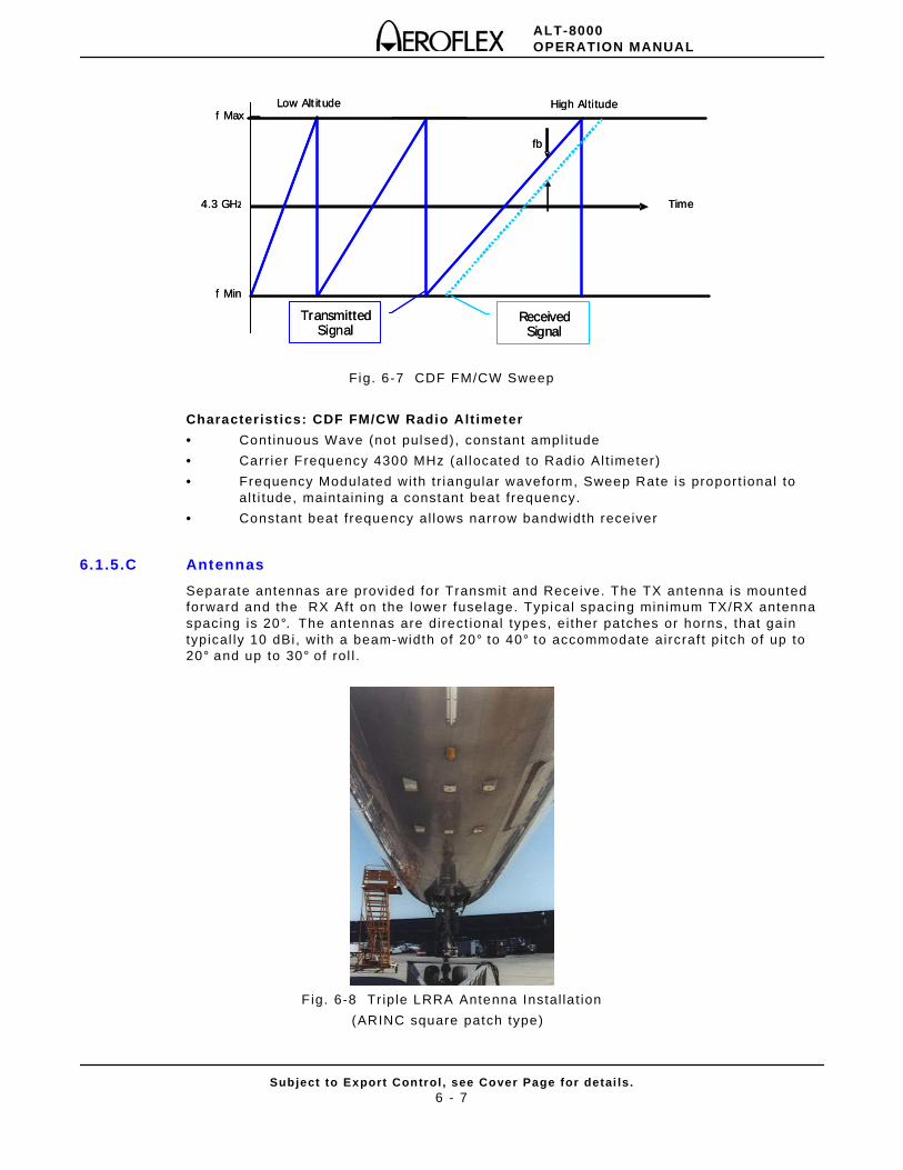
ALT-8000OPERATION MANUAL
Subject to Export Control , see Cover Page for detai ls .6 - 7
Fig. 6-7 CDF FM/CW Sweep
Characterist ics: CDF FM/CW Radio Alt imeter
• Continuous Wave (not pulsed), constant ampl i tude
• Carr ier Frequency 4300 MHz (al located to Radio Al t imeter)
• Frequency Modulated with t r iangular waveform, Sweep Rate is proport ional to al t i tude, maintaining a constant beat f requency.
• Constant beat f requency al lows narrow bandwidth receiver
6.1.5.C Antennas
Separate antennas are provided for Transmit and Receive. The TX antenna is mounted forward and the RX Aft on the lower fuselage. Typical spacing minimum TX/RX antenna spacing is 20°. The antennas are direct ional types, ei ther patches or horns, that ga in typical ly 10 dBi, wi th a beam-width of 20° to 40° to accommodate aircraf t pi tch of up to 20° and up to 30° of rol l .
F ig. 6-8 Tr iple LRRA Antenna Instal la t ion
(ARINC square patch type)
f Max
f Min
Time4.3 GHz
fb
Low Altitude High Altitudef Max
f Min
Time4.3 GHz
fb
Low Altitude High Altitude
Received Signal
Received SignalSignal
Transmitted Transmitted Signal
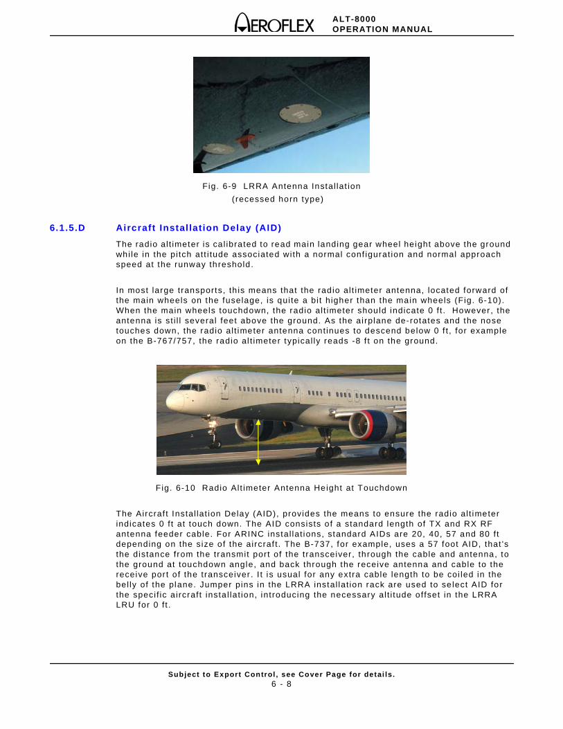
ALT-8000OPERATION MANUAL
Subject to Export Control , see Cover Page for detai ls .6 - 8
Fig. 6-9 LRRA Antenna Instal lat ion
( recessed horn type)
6.1.5.D Aircraft Instal lation Delay (AID)
The radio al t imeter is ca l ibrated to read main landing gear wheel height above the ground whi le in the pi tch att i tude associated with a normal conf igurat ion and normal approach speed at the runway threshold.
In most large transports, th is means that the rad io al t imeter antenna, located forward of the main wheels on the fuselage, is qui te a bi t h igher than the main wheels (Fig. 6-10). When the main wheels touchdown, the radio al t imeter should indicate 0 f t . However, the antenna is st i l l several feet above the ground. As the ai rplane de-rotates and the nose touches down, the radio al t imeter antenna cont inues to descend below 0 f t , for example on the B-767/757, the radio al t imeter typical ly reads -8 f t on the ground.
Fig. 6-10 Radio Alt imeter Antenna Height at Touchdown
The Aircraf t Instal lat ion Delay (AID), provides the means to ensure the radio al t imeter indicates 0 f t at touch down. The AID consists o f a standard length of TX and RX RF antenna feeder cable. For ARINC instal lat ions, standard AIDs are 20, 40, 57 and 80 f t depending on the size of the aircraf t . The B-737, for example, uses a 57 foot AID, that 's the distance from the transmit port of the transceiver, through the cable and antenna, to the ground at touchdown angle, and back through the receive antenna and cable to the receive por t o f the transceiver . I t is usual for any extra cable length to be coi led in the bel ly of the plane. Jumper pins in the LRRA instal lat ion rack are used to se lect AID for the speci f ic aircraft insta l lat ion, introducing the necessary al t i tude offset in the LRRA LRU for 0 f t .
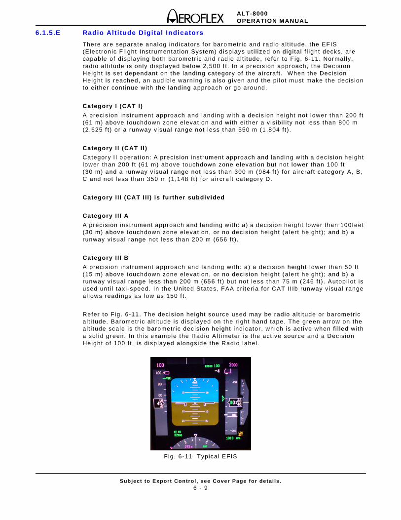
ALT-8000OPERATION MANUAL
Subject to Export Control , see Cover Page for detai ls .6 - 9
6.1.5.E Radio Alt i tude Digital Indicators
There are separate analog ind icators for barometr ic and radio a l t i tude, the EFIS (Electronic F l ight Inst rumentat ion System) displays ut i l ized on dig i tal f l ight decks, are capable of displaying both barometr ic and rad io al t i tude, refer to Fig. 6-11. Normal ly, rad io al t i tude is on ly displayed below 2,500 f t . In a precision approach, the Decision Height is set dependant on the landing category of the aircraft . When the Decision Height is reached, an audible warn ing is a lso g iven and the pi lo t must make the decision to ei ther cont inue with the landing approach or go around.
Category I (CAT I)
A precision inst rument approach and landing with a decision height not lower than 200 f t (61 m) above touchdown zone elevat ion and with ei ther a vis ibi l i ty not less than 800 m (2,625 f t) or a runway visual range not less than 550 m (1,804 f t ) .
Category I I (CAT II )
Category I I operat ion: A precision inst rument approach and landing with a decision height lower than 200 f t (61 m) above touchdown zone elevat ion but not lower than 100 f t (30 m) and a runway visual range not less than 300 m (984 f t ) for aircraft category A, B, C and not less than 350 m (1,148 f t ) for aircraf t category D.
Category I I I (CAT I I I ) is further subdivided
Category I I I A
A precision instrument approach and landing with: a) a decision height lower than 100feet (30 m) above touchdown zone elevat ion, or no decision height (alert height) ; and b) a runway visual range not less than 200 m (656 f t) .
Category I I I B
A precision inst rument approach and landing with: a) a decision height lower than 50 f t (15 m) above touchdown zone elevat ion, or no decision height (alert height) ; and b) a runway visual range less than 200 m (656 f t ) but not less than 75 m (246 f t ) . Autopi lot is used unt i l taxi-speed. In the United States, FAA cr i ter ia for CAT I I Ib runway visual range al lows readings as low as 150 f t .
Refer to Fig. 6-11. The decision height source used may be radio a l t i tude or barometr ic al t i tude. Barometr ic al t i tude is d isplayed on the r ight hand tape. The green arrow on the al t i tude scale is the barometr ic decision height indicator, which is act ive when f i l led with a sol id green. In this example the Radio Al t imeter is the act ive source and a Decision Height of 100 f t , is displayed alongside the Radio label.
Fig. 6-11 Typical EFIS
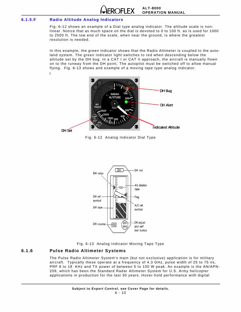
ALT-8000OPERATION MANUAL
Subject to Export Control , see Cover Page for detai ls .6 - 10
6.1.5.F Radio Alt i tude Analog Indicators
Fig. 6-12 shows an example of a Dial type analog indicator . The al t i tude scale is non-l inear . Not ice that as much space on the d ial is devoted to 0 to 100 f t . as is used for 1000 to 2500 f t . The low end of the scale, when near the ground, is where the greatest resolut ion is needed.
In this example, the green indicator shows that the Radio Al t imeter is coupled to the auto-land system. The green indicator l ight switches to red when descending below the al t i tude set by the DH bug. In a CAT I or CAT I I approach, the aircraf t is manual ly f lown on to the runway from the DH point. The autopi lot must be swi tched off to a l low manual f ly ing. Fig. 6-13 shows and example of a moving tape type analog indicator.
l
F ig. 6-12 Analog Indicator Dial Type
Fig. 6-13 Analog Indicator Moving Tape Type
6.1.6 Pulse Radio Alt imeter Systems
The Pulse Radio Al t imeter System’s main (but not exclusive) appl icat ion is for mi l i tary aircraft . Typical ly these operate at a frequency of 4.3 GHz, pulse width of 25 to 75 ns, PRF 8 to 18 KHz and TX power of between 5 to 100 W peak. An example is the AN/APN-209, which has been the Standard Radar Alt imeter System for U.S. Army hel icopter appl icat ions in product ion for the last 30 years. Hover-hold performance wi th digi tal
DH Set
DH Bug
DH Alert
Indicated AltitudeDH Set
DH Bug
DH Alert
Indicated Altitude
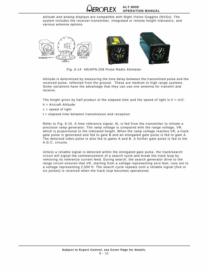
ALT-8000OPERATION MANUAL
Subject to Export Control , see Cover Page for detai ls .6 - 11
alt i tude and analog d isplays are compatible wi th Night Vision Goggles (NVGs). The system includes the receiver-transmit ter, integrated or remote height indicators, and var ious antenna opt ions.
Fig. 6-14 AN/APN-209 Pulse Radio Alt imeter
Alt i tude is determined by measuring the t ime delay between the t ransmit ted pulse and the received pulse, ref lected f rom the ground. These are medium to high range systems. Some var ia t ions have the advantage that they can use one antenna for t ransmi t and receive.
The height given by ha l f product of the elapsed t ime and the speed of l ight is h = ct /2.
h = Aircraf t A l t i tude
c = speed of l ight
t = elapsed t ime between transmission and recept ion
Refer to Fig. 6-15. A t ime reference signal , t0, is fed from the transmit ter to ini t iate a precis ion ramp generator. The ramp vol tage is compared with the range vo l tage, VR, which is proport ional to the indicated height. When the ramp vo l tage reaches VR, a track gate pulse is generated and fed to gate B and an elongated gate pulse is fed to gate A. The detected video pulse is also fed to gates A and B. A further gate pulse is fed to the A.G.C. circui ts.
Unless a rel iab le signal is detected within the elongated gate pulse, the track/search circui t wi l l s ignal the commencement o f a search cycle and break the track loop by removing i ts reference current feed. During search, the search generator dr ive to the range circui t ensures that VR, star t ing from a vol tage represent ing zero feet, runs out to a vol tage represent ing 2,500 f t . The search cycle repeats unt i l a rel iable signal ( f ive or s ix pulses) is received when the t rack loop becomes operat ional .
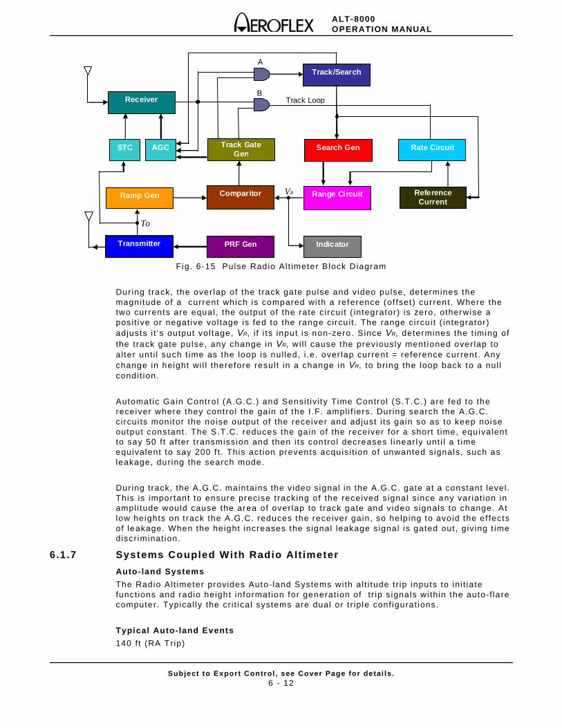
ALT-8000OPERATION MANUAL
Subject to Export Control , see Cover Page for detai ls .6 - 12
Fig. 6-15 Pulse Radio Al t imeter Block Diagram
During track, the over lap of the t rack gate pulse and video pulse, determines the magnitude of a current which is compared with a reference (of fset ) current. Where the two currents are equal, the output of the rate circu i t ( integrator) is zero, otherwise a posi t ive or negat ive vol tage is fed to the range circu i t . The range circu i t ( integrator) adjusts i t ’s output vol tage, VR, i f i ts input is non-zero. Since VR, determines the t iming of the track gate pulse, any change in VR, wi l l cause the previously ment ioned overlap to al ter unt i l such t ime as the loop is nul led, i .e. over lap current = re ference current . Any change in height wi l l therefore resul t in a change in VR, to br ing the loop back to a nul l condit ion.
Automatic Gain Control (A.G.C.) and Sensit iv i ty Time Control (S.T.C.) are fed to the receiver where they control the gain of the I .F. ampl i f iers. During search the A.G.C. c ircui ts monitor the noise output of the receiver and adjust i ts gain so as to keep noise output constant. The S.T.C. reduces the gain of the receiver for a short t ime, equivalent to say 50 f t af ter t ransmission and then i ts contro l decreases l inear ly unt i l a t ime equivalent to say 200 f t . This act ion prevents acquisi t ion of unwanted signals, such as leakage, dur ing the search mode.
During track, the A.G.C. maintains the video signal in the A.G.C. gate at a constant level . This is important to ensure precise t racking of the received signal s ince any var iat ion in ampl i tude would cause the area of overlap to t rack gate and video signals to change. At low heights on t rack the A.G.C. reduces the receiver gain , so help ing to avoid the ef fects of leakage. When the height increases the signal leakage signal is gated out, giv ing t ime discr iminat ion.
6.1.7 Systems Coupled With Radio Alt imeter
Auto-land Systems
The Radio Al t imeter provides Auto- land Systems with al t i tude t r ip inputs to in i t iate funct ions and radio height information for generat ion of t r ip s ignals within the auto-f lare computer. Typical ly the cr i t ical systems are dual or t r ip le conf igurat ions.
Typical Auto- land Events
140 f t (RA Trip)
To
VR
B
A
Track Loop Receiver
Track/Search
STC
Indicator
Track Gate Gen
Comparitor
Search Gen AGC
Ramp Gen
Transmitter PRF Gen
Rate Circuit
Range Circuit Reference Current
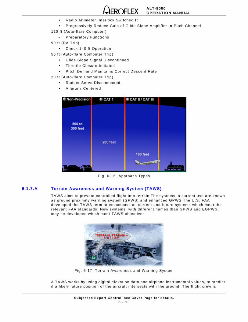
ALT-8000OPERATION MANUAL
Subject to Export Control , see Cover Page for detai ls .6 - 13
• Radio Al t imeter Inter lock Swi tched In
• Progressively Reduce Gain of Gl ide Slope Ampl i f ier In Pi tch Channel
120 f t (Auto-f lare Computer)
• Preparatory Funct ions
90 f t (RA Tr ip)
• Check 140 f t Operat ion
50 f t (Auto-f lare Computer Tr ip)
• Glide Slope Signal Discont inued
• Thrott le Closure Ini t iated
• Pitch Demand Maintains Correct Descent Rate
20 f t (Auto-f lare Computer Tr ip)
• Rudder Servo Disconnected
• Ailerons Centered
Fig. 6-16 Approach Types
6.1.7.A Terrain Awareness and Warning System (TAWS)
TAWS aims to prevent control led f l ight into terrain The systems in current use are known as ground proximi ty warning system (GPWS) and enhanced GPWS The U.S. FAA developed the TAWS term to encompass a l l current and future systems which meet the relevant FAA standards. New systems, with di f ferent names than GPWS and EGPWS, may be developed which meet TAWS object ives
Fig. 6-17 Terrain Awareness and Warning System
A TAWS works by using digi ta l e levat ion data and airplane instrumental va lues, to predict i f a l ikely future posi t ion of the aircraft intersects with the ground. The f l ight crew is
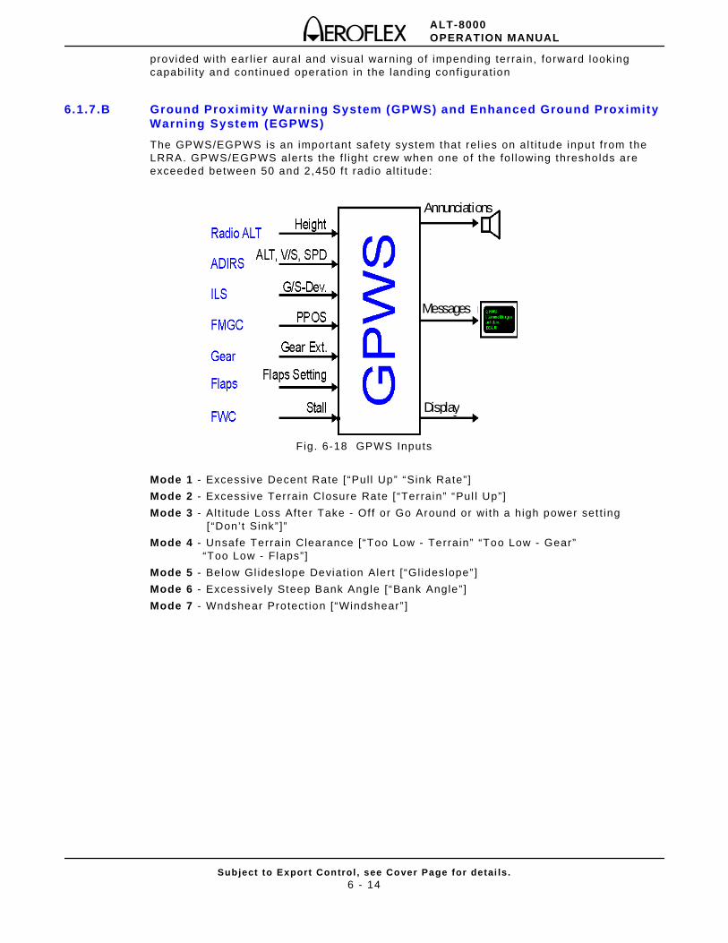
ALT-8000OPERATION MANUAL
Subject to Export Control , see Cover Page for detai ls .6 - 14
provided with ear l ier aura l and visual warning of impending terrain, forward looking capabi l i ty and cont inued operat ion in the landing conf igurat ion
6.1.7.B Ground Proximity Warning System (GPWS) and Enhanced Ground Proximity Warning System (EGPWS)
The GPWS/EGPWS is an important safety system that rel ies on al t i tude input f rom the LRRA. GPWS/EGPWS aler ts the f l ight crew when one of the fo l lowing thresholds are exceeded between 50 and 2,450 f t radio al t i tude:
Fig. 6-18 GPWS Inputs
Mode 1 - Excessive Decent Rate [“Pul l Up” “Sink Rate”]
Mode 2 - Excessive Terrain Closure Rate [ “Terrain” “Pul l Up”]
Mode 3 - Al t i tude Loss After Take - Off or Go Around or with a high power set t ing [ “Don’t Sink” ]”
Mode 4 - Unsafe Terrain Clearance [“Too Low - Terrain” “Too Low - Gear” “Too Low - Flaps”]
Mode 5 - Below Gl ideslope Deviat ion Alert [ “Gl ideslope” ]
Mode 6 - Excessive ly Steep Bank Angle [“Bank Angle”]
Mode 7 - Wndshear Protect ion [“Windshear” ]
Messages
Display
Annunciations
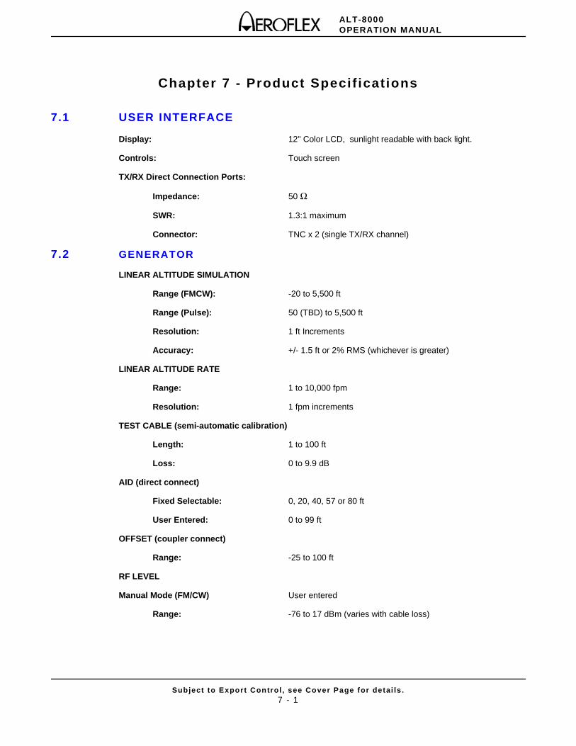
ALT-8000OPERATION MANUAL
Subject to Export Control , see Cover Page for detai ls .7 - 1
Chapter 7 - Product Specif ications
7.1 USER INTERFACE
Display: 12" Color LCD, sunlight readable with back light.
Controls: Touch screen
TX/RX Direct Connection Ports:
Impedance: 50 Ω
SWR: 1.3:1 maximum
Connector: TNC x 2 (single TX/RX channel)
7.2 GENERATOR
LINEAR ALTITUDE SIMULATION
Range (FMCW): -20 to 5,500 ft
Range (Pulse): 50 (TBD) to 5,500 ft
Resolution: 1 ft Increments
Accuracy: +/- 1.5 ft or 2% RMS (whichever is greater)
LINEAR ALTITUDE RATE
Range: 1 to 10,000 fpm
Resolution: 1 fpm increments
TEST CABLE (semi-automatic calibration)
Length: 1 to 100 ft
Loss: 0 to 9.9 dB
AID (direct connect)
Fixed Selectable: 0, 20, 40, 57 or 80 ft
User Entered: 0 to 99 ft
OFFSET (coupler connect)
Range: -25 to 100 ft
RF LEVEL
Manual Mode (FM/CW) User entered
Range: -76 to 17 dBm (varies with cable loss)
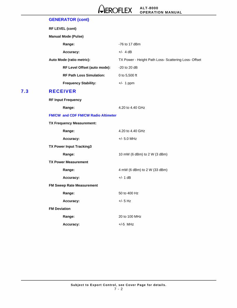
ALT-8000OPERATION MANUAL
Subject to Export Control , see Cover Page for detai ls .7 - 2
GENERATOR (cont)
RF LEVEL (cont)
Manual Mode (Pulse)
Range: -76 to 17 dBm
Accuracy: +/- 4 dB
Auto Mode (ratio metric): TX Power - Height Path Loss- Scattering Loss- Offset
RF Level Offset (auto mode): -20 to 20 dB
RF Path Loss Simulation: 0 to 5,500 ft
Frequency Stability: +/- 1 ppm
7.3 RECEIVER
RF Input Frequency
Range: 4.20 to 4.40 GHz
FM/CW and CDF FM/CW Radio Altimeter
TX Frequency Measurement:
Range: 4.20 to 4.40 GHz
Accuracy: +/- 5.0 MHz
TX Power Input Tracking3
Range: 10 mW (6 dBm) to 2 W (3 dBm)
TX Power Measurement
Range: 4 mW (6 dBm) to 2 W (33 dBm)
Accuracy: +/- 1 dB
FM Sweep Rate Measurement
Range: 50 to 400 Hz
Accuracy: +/- 5 Hz
FM Deviation
Range: 20 to 100 MHz
Accuracy: +/-5 MHz
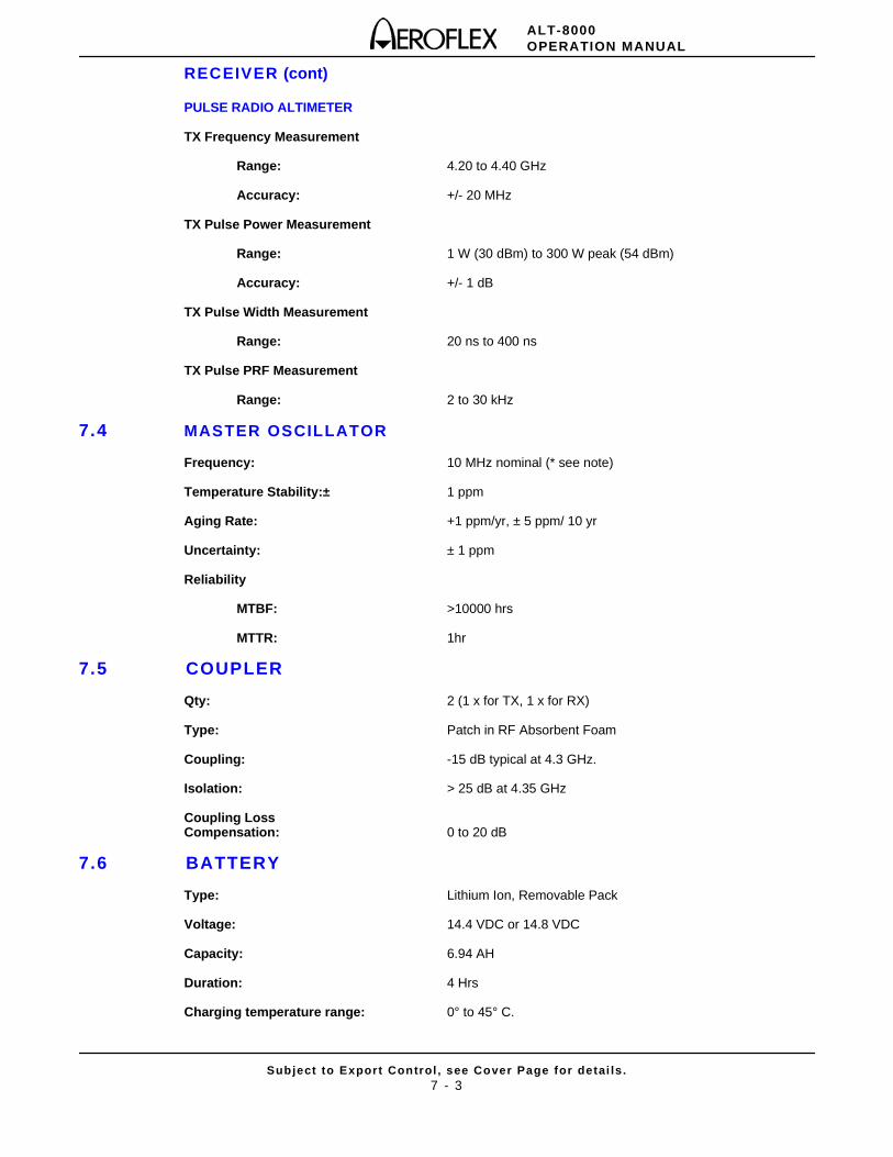
ALT-8000OPERATION MANUAL
Subject to Export Control , see Cover Page for detai ls .7 - 3
RECEIVER (cont)
PULSE RADIO ALTIMETER
TX Frequency Measurement
Range: 4.20 to 4.40 GHz
Accuracy: +/- 20 MHz
TX Pulse Power Measurement
Range: 1 W (30 dBm) to 300 W peak (54 dBm)
Accuracy: +/- 1 dB
TX Pulse Width Measurement
Range: 20 ns to 400 ns
TX Pulse PRF Measurement
Range: 2 to 30 kHz
7.4 MASTER OSCILLATOR
Frequency: 10 MHz nominal (* see note)
Temperature Stability:± 1 ppm
Aging Rate: +1 ppm/yr, ± 5 ppm/ 10 yr
Uncertainty: ± 1 ppm
Reliability
MTBF: >10000 hrs
MTTR: 1hr
7.5 COUPLER
Qty: 2 (1 x for TX, 1 x for RX)
Type: Patch in RF Absorbent Foam
Coupling: -15 dB typical at 4.3 GHz.
Isolation: > 25 dB at 4.35 GHz
Coupling LossCompensation: 0 to 20 dB
7.6 BATTERY
Type: Lithium Ion, Removable Pack
Voltage: 14.4 VDC or 14.8 VDC
Capacity: 6.94 AH
Duration: 4 Hrs
Charging temperature range: 0° to 45° C.
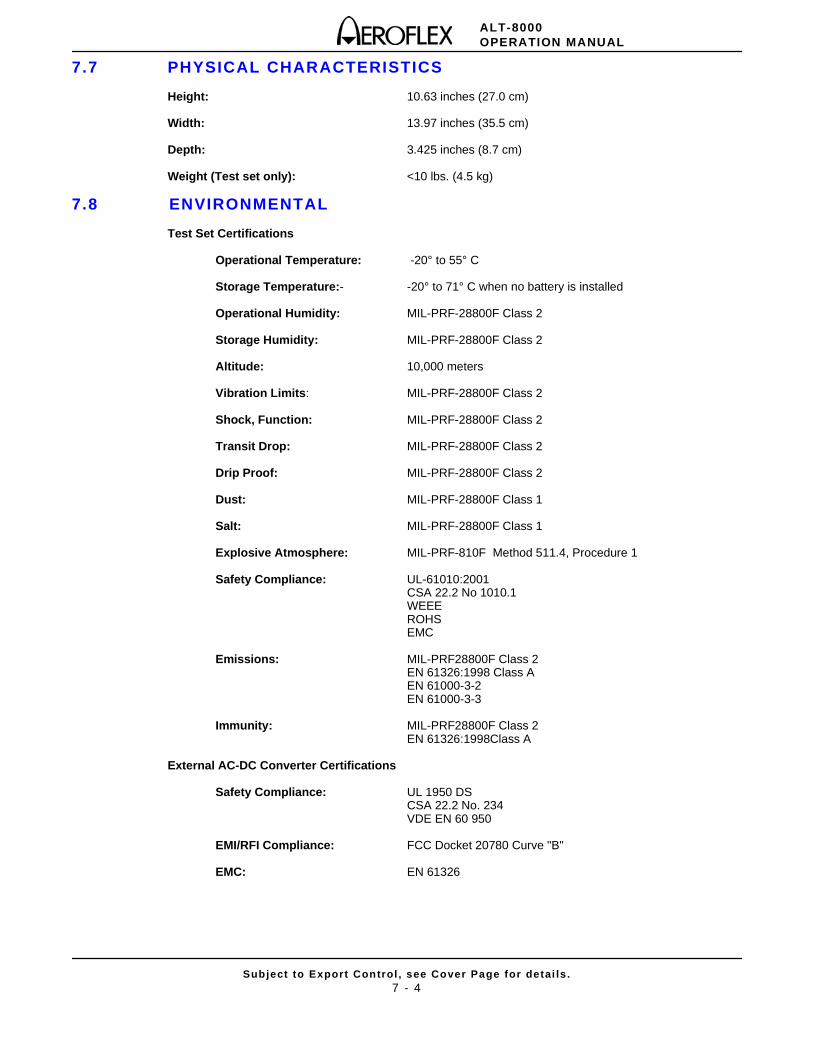
ALT-8000OPERATION MANUAL
Subject to Export Control , see Cover Page for detai ls .7 - 4
7.7 PHYSICAL CHARACTERISTICS
Height: 10.63 inches (27.0 cm)
Width: 13.97 inches (35.5 cm)
Depth: 3.425 inches (8.7 cm)
Weight (Test set only): <10 lbs. (4.5 kg)
7.8 ENVIRONMENTAL
Test Set Certifications
Operational Temperature: -20° to 55° C
Storage Temperature:- -20° to 71° C when no battery is installed
Operational Humidity: MIL-PRF-28800F Class 2
Storage Humidity: MIL-PRF-28800F Class 2
Altitude: 10,000 meters
Vibration Limits: MIL-PRF-28800F Class 2
Shock, Function: MIL-PRF-28800F Class 2
Transit Drop: MIL-PRF-28800F Class 2
Drip Proof: MIL-PRF-28800F Class 2
Dust: MIL-PRF-28800F Class 1
Salt: MIL-PRF-28800F Class 1
Explosive Atmosphere: MIL-PRF-810F Method 511.4, Procedure 1
Safety Compliance: UL-61010:2001CSA 22.2 No 1010.1WEEEROHSEMC
Emissions: MIL-PRF28800F Class 2EN 61326:1998 Class AEN 61000-3-2 EN 61000-3-3
Immunity: MIL-PRF28800F Class 2EN 61326:1998Class A
External AC-DC Converter Certifications
Safety Compliance: UL 1950 DSCSA 22.2 No. 234VDE EN 60 950
EMI/RFI Compliance: FCC Docket 20780 Curve "B"
EMC: EN 61326
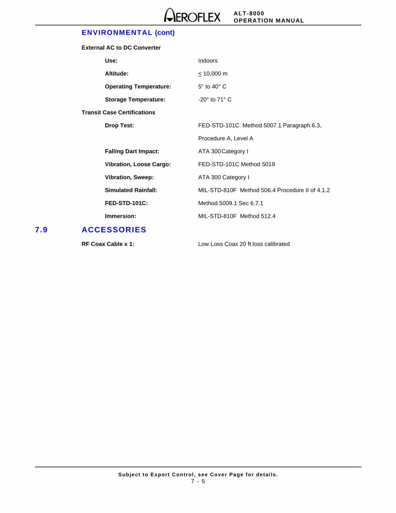
ALT-8000OPERATION MANUAL
Subject to Export Control , see Cover Page for detai ls .7 - 5
ENVIRONMENTAL (cont)
External AC to DC Converter
Use: Indoors
Altitude: < 10,000 m
Operating Temperature: 5° to 40° C
Storage Temperature: -20° to 71° C
Transit Case Certifications
Drop Test: FED-STD-101C Method 5007.1 Paragraph 6.3,
Procedure A, Level A
Falling Dart Impact: ATA 300Category I
Vibration, Loose Cargo: FED-STD-101C Method 5019
Vibration, Sweep: ATA 300 Category I
Simulated Rainfall: MIL-STD-810F Method 506.4 Procedure II of 4.1.2
FED-STD-101C: Method 5009.1 Sec 6.7.1
Immersion: MIL-STD-810F Method 512.4
7.9 ACCESSORIES
RF Coax Cable x 1: Low Loss Coax 20 ft loss calibrated

ALT-8000OPERATION MANUAL
Subject to Export Control , see Cover Page for detai ls .7 - 6
THIS PAGE INTENTIONALLY LEFT BLANK.
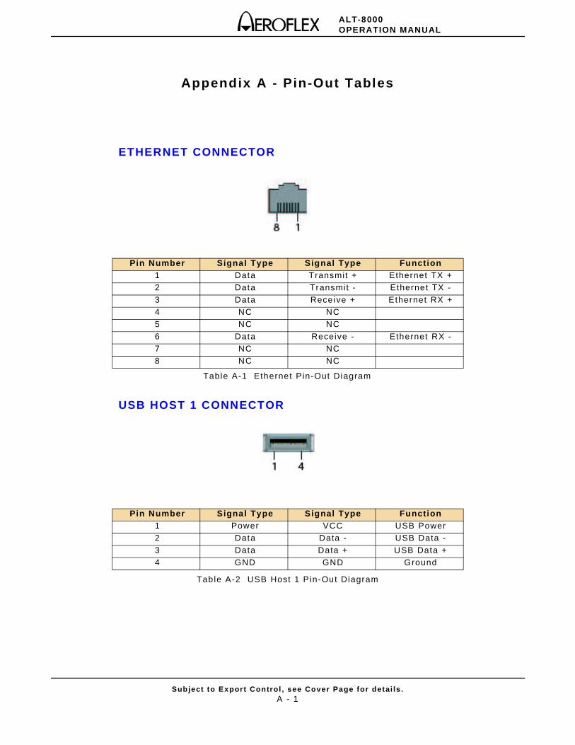
ALT-8000OPERATION MANUAL
Subject to Export Control , see Cover Page for detai ls .A - 1
Appendix A - Pin-Out Tables
ETHERNET CONNECTOR
Table A-1 Ethernet Pin-Out Diagram
USB HOST 1 CONNECTOR
Table A-2 USB Host 1 Pin-Out Diagram
Pin Number Signal Type Signal Type Function1 Data Transmit + Ethernet TX +2 Data Transmit - Ethernet TX -
3 Data Receive + Ethernet RX +4 NC NC5 NC NC
6 Data Receive - Ethernet RX -7 NC NC8 NC NC
Pin Number Signal Type Signal Type Function1 Power VCC USB Power2 Data Data - USB Data -
3 Data Data + USB Data +4 GND GND Ground
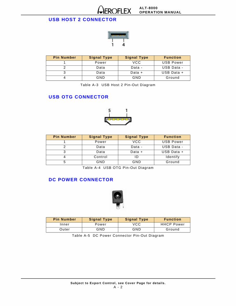
ALT-8000OPERATION MANUAL
Subject to Export Control , see Cover Page for detai ls .A - 2
USB HOST 2 CONNECTOR
Table A-3 USB Host 2 Pin-Out Diagram
USB OTG CONNECTOR
Table A-4 USB OTG Pin-Out Diagram
DC POWER CONNECTOR
Table A-5 DC Power Connector Pin-Out Diagram
Pin Number Signal Type Signal Type Function1 Power VCC USB Power2 Data Data - USB Data -3 Data Data + USB Data +
4 GND GND Ground
Pin Number Signal Type Signal Type Function1 Power VCC USB Power
2 Data Data - USB Data -3 Data Data + USB Data +4 Control ID Ident i fy
5 GND GND Ground
Pin Number Signal Type Signal Type FunctionInner Power VCC HHCP PowerOuter GND GND Ground

ALT-8000OPERATION MANUAL
Subject to Export Control , see Cover Page for detai ls .A - 3
AUX CONNECTOR
Currently not in use.

ALT-8000OPERATION MANUAL
Subject to Export Control , see Cover Page for detai ls .A - 4
THIS PAGE INTENTIONALLY LEFT BLANK.
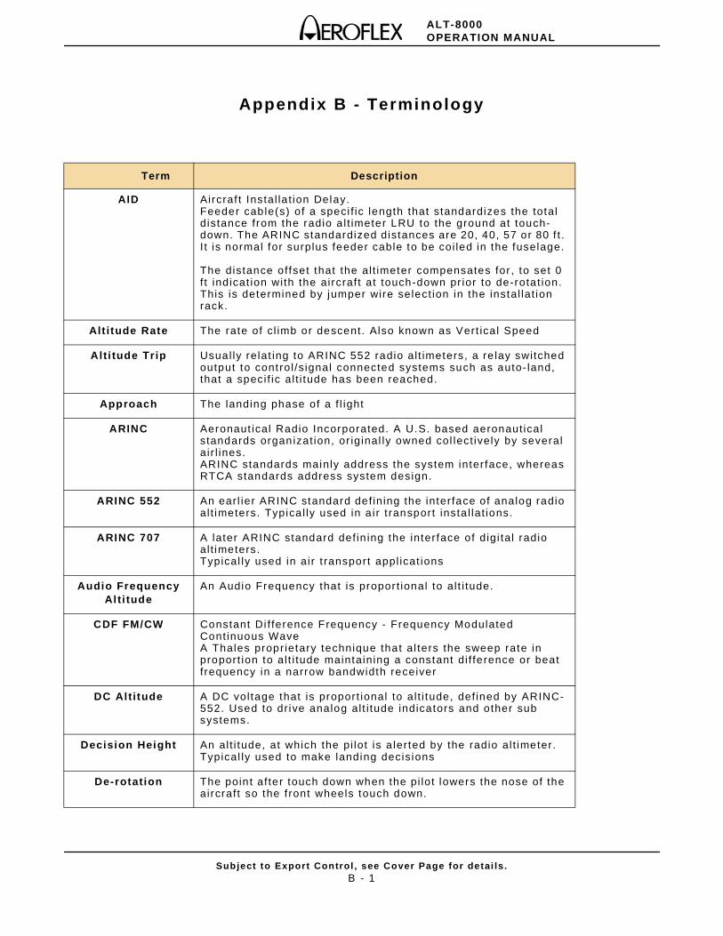
ALT-8000OPERATION MANUAL
Subject to Export Control , see Cover Page for detai ls .B - 1
Appendix B - Terminology
Term Description
AID Aircraf t Instal la t ion Delay.Feeder cable(s) of a speci f ic length that standardizes the total distance from the radio a l t imeter LRU to the ground at touch-down. The ARINC standardized distances are 20, 40, 57 or 80 f t . I t is normal for surplus feeder cable to be coi led in the fuselage.
The distance offset that the al t imeter compensates for , to set 0 f t indicat ion with the aircraft at touch-down pr ior to de-rotat ion. This is determined by jumper wire select ion in the instal lat ion rack.
Alt itude Rate The rate of c l imb or descent. Also known as Vert ical Speed
Alti tude Trip Usual ly relat ing to ARINC 552 radio al t imeters, a re lay switched output to control /s ignal connected systems such as auto- land, that a speci f ic al t i tude has been reached.
Approach The landing phase of a f l ight
ARINC Aeronaut ical Radio Incorporated. A U.S. based aeronaut ical standards organizat ion, or iginal ly owned col lect ively by several air l ines.ARINC standards mainly address the system interface, whereas RTCA standards address system design.
ARINC 552 An earl ier ARINC standard def ining the interface of analog radio al t imeters. Typica l ly used in a ir t ransport insta l lat ions.
ARINC 707 A later ARINC standard def in ing the interface of digi tal radio al t imeters.Typical ly used in air t ransport appl icat ions
Audio Frequency Alti tude
An Audio Frequency that is propor t ional to al t i tude.
CDF FM/CW Constant Di f ference Frequency - Frequency Modulated Cont inuous WaveA Thales proprietary technique that al ters the sweep rate in proport ion to al t i tude maintaining a constant di f ference or beat f requency in a narrow bandwidth receiver
DC Altitude A DC voltage that is proport ional to al t i tude, def ined by ARINC-552. Used to dr ive analog al t i tude indicators and other sub systems.
Decision Height An al t i tude, at which the pi lot is a lerted by the radio al t imeter. Typical ly used to make landing decisions
De-rotation The point af ter touch down when the pi lot lowers the nose of the aircraft so the f ront wheels touch down.
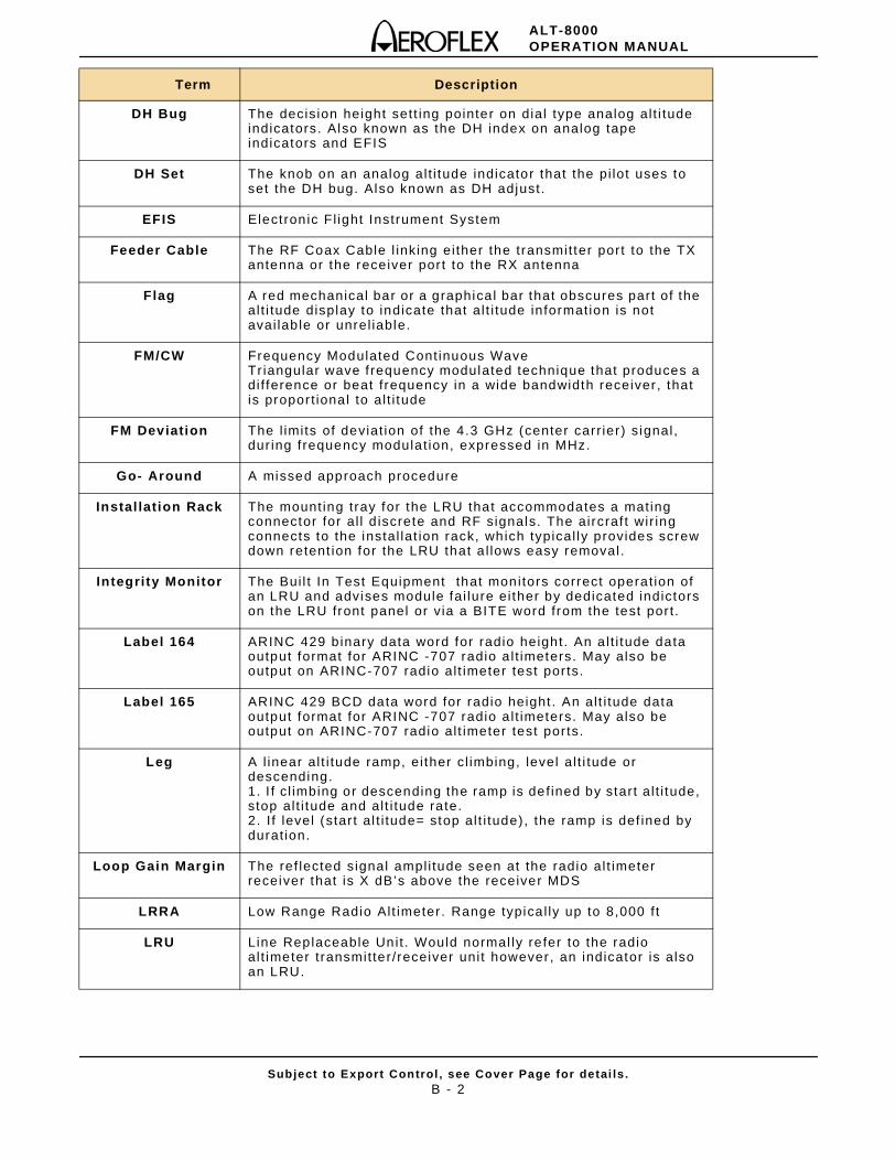
ALT-8000OPERATION MANUAL
Subject to Export Control , see Cover Page for detai ls .B - 2
Term Description
DH Bug The decision height sett ing pointer on dial type analog al t i tude indicators. Also known as the DH index on analog tape indicators and EFIS
DH Set The knob on an analog al t i tude indicator that the pi lot uses to set the DH bug. Also known as DH adjust.
EFIS Elect ron ic Fl ight Instrument System
Feeder Cable The RF Coax Cable l inking ei ther the transmit ter port to the TX antenna or the receiver por t to the RX antenna
Flag A red mechanical bar or a graphica l bar that obscures part of the al t i tude display to indicate that al t i tude information is not avai lab le or unrel iable.
FM/CW Frequency Modulated Cont inuous Wave Tr iangular wave f requency modulated technique that produces a di f ference or beat f requency in a wide bandwidth receiver , that is propor t ional to al t i tude
FM Deviation The l imits of deviat ion of the 4.3 GHz (center carr ier ) s ignal, dur ing f requency modulat ion, expressed in MHz.
Go- Around A missed approach procedure
Instal lation Rack The mount ing tray for the LRU that accommodates a mating connector for al l d iscrete and RF signals. The aircraf t wir ing connects to the instal lat ion rack, which typical ly provides screw down retent ion for the LRU that a l lows easy removal.
Integrity Monitor The Bui l t In Test Equipment that monitors correct operat ion of an LRU and advises module fai lure ei ther by dedicated indictors on the LRU front panel or v ia a BITE word from the test por t .
Label 164 ARINC 429 b inary data word for radio height. An a l t i tude data output format for ARINC -707 radio a l t imeters. May also be output on ARINC-707 radio al t imeter test por ts.
Label 165 ARINC 429 BCD data word for radio height . An al t i tude data output format for ARINC -707 radio a l t imeters. May also be output on ARINC-707 radio al t imeter test por ts.
Leg A l inear al t i tude ramp, ei ther c l imbing, level al t i tude or descending.1. I f c l imbing or descending the ramp is def ined by start al t i tude, stop al t i tude and al t i tude rate.2. I f level (star t al t i tude= stop al t i tude), the ramp is def ined by durat ion.
Loop Gain Margin The ref lected signal ampl i tude seen at the radio al t imeter receiver that is X dB’s above the receiver MDS
LRRA Low Range Radio Alt imeter . Range typica l ly up to 8,000 f t
LRU Line Replaceable Unit . Would normal ly re fer to the radio al t imeter t ransmit ter/receiver uni t however, an indicator is also an LRU.
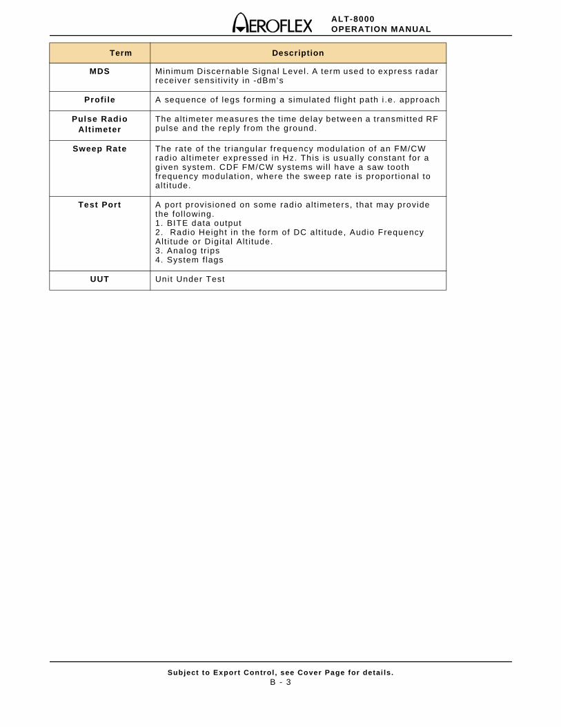
ALT-8000OPERATION MANUAL
Subject to Export Control , see Cover Page for detai ls .B - 3
Term Description
MDS Minimum Discernable Signal Level. A term used to express radar receiver sensi t iv i ty in -dBm’s
Profi le A sequence of legs forming a simulated f l ight path i .e. approach
Pulse Radio Alt imeter
The al t imeter measures the t ime delay between a transmi t ted RF pulse and the reply f rom the ground.
Sweep Rate The rate of the tr iangular f requency modulat ion of an FM/CW radio al t imeter expressed in Hz. Th is is usual ly constant for a given system. CDF FM/CW systems wi l l have a saw tooth frequency modulat ion, where the sweep rate is propor t ional to al t i tude.
Test Port A port provisioned on some rad io al t imeters, that may provide the fol lowing.1. BITE data output2. Radio Height in the form of DC al t i tude, Audio Frequency Alt i tude or Digi tal Al t i tude.3. Analog tr ips4. System f lags
UUT Unit Under Test

ALT-8000OPERATION MANUAL
Subject to Export Control , see Cover Page for detai ls .B - 4
THIS PAGE INTENTIONALLY LEFT BLANK.

ALT-8000OPERATION MANUAL
Subject to Export Control , see Cover Page for detai ls .B - 5
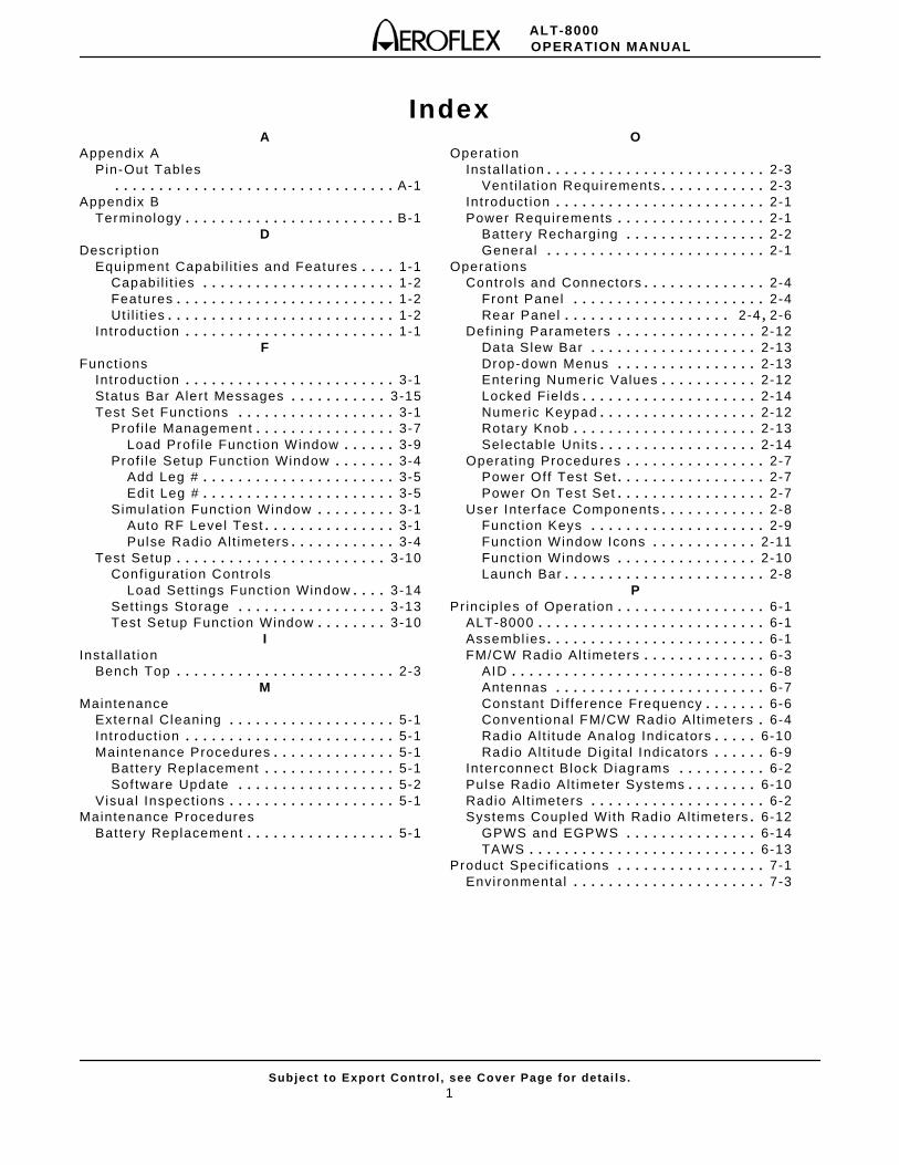
ALT-8000OPERATION MANUAL
Subject to Export Control , see Cover Page for detai ls .1
IndexA
Appendix APin-Out Tables
. . . . . . . . . . . . . . . . . . . . . . . . . . . . . . . . A-1Appendix B
Terminology . . . . . . . . . . . . . . . . . . . . . . . . B-1D
Descr ipt ionEquipment Capabi l i t ies and Features . . . . 1-1
Capabi l i t ies . . . . . . . . . . . . . . . . . . . . . . 1-2Features . . . . . . . . . . . . . . . . . . . . . . . . . 1-2Ut i l i t ies . . . . . . . . . . . . . . . . . . . . . . . . . . 1-2
Int roduct ion . . . . . . . . . . . . . . . . . . . . . . . . 1-1F
Funct ionsInt roduct ion . . . . . . . . . . . . . . . . . . . . . . . . 3-1Status Bar Alert Messages . . . . . . . . . . . 3-15Test Set Funct ions . . . . . . . . . . . . . . . . . . 3-1
Prof i le Management . . . . . . . . . . . . . . . . 3-7Load Prof i le Funct ion Window . . . . . . 3-9
Prof i le Setup Funct ion Window . . . . . . . 3-4Add Leg # . . . . . . . . . . . . . . . . . . . . . . 3-5Edi t Leg # . . . . . . . . . . . . . . . . . . . . . . 3-5
Simulat ion Funct ion Window . . . . . . . . . 3-1Auto RF Level Test . . . . . . . . . . . . . . . 3-1Pulse Radio Al t imeters . . . . . . . . . . . . 3-4
Test Setup . . . . . . . . . . . . . . . . . . . . . . . . 3-10Configurat ion Controls
Load Set t ings Funct ion Window . . . . 3-14Set t ings Storage . . . . . . . . . . . . . . . . . 3-13Test Setup Funct ion Window . . . . . . . . 3-10
IInstal lat ion
Bench Top . . . . . . . . . . . . . . . . . . . . . . . . . 2-3M
MaintenanceExternal Cleaning . . . . . . . . . . . . . . . . . . . 5-1Int roduct ion . . . . . . . . . . . . . . . . . . . . . . . . 5-1Maintenance Procedures . . . . . . . . . . . . . . 5-1
Bat tery Replacement . . . . . . . . . . . . . . . 5-1Sof tware Update . . . . . . . . . . . . . . . . . . 5-2
Visual Inspect ions . . . . . . . . . . . . . . . . . . . 5-1Maintenance Procedures
Bat tery Replacement . . . . . . . . . . . . . . . . . 5-1
OOperat ion
Instal lat ion . . . . . . . . . . . . . . . . . . . . . . . . . 2-3Venti lat ion Requi rements . . . . . . . . . . . . 2-3
Int roduct ion . . . . . . . . . . . . . . . . . . . . . . . . 2-1Power Requirements . . . . . . . . . . . . . . . . . 2-1
Bat tery Recharging . . . . . . . . . . . . . . . . 2-2General . . . . . . . . . . . . . . . . . . . . . . . . . 2-1
Operat ionsContro ls and Connectors . . . . . . . . . . . . . . 2-4
Front Panel . . . . . . . . . . . . . . . . . . . . . . 2-4Rear Panel . . . . . . . . . . . . . . . . . . . 2-4 , 2-6
Defining Parameters . . . . . . . . . . . . . . . . 2-12Data Slew Bar . . . . . . . . . . . . . . . . . . . 2-13Drop-down Menus . . . . . . . . . . . . . . . . 2-13Enter ing Numeric Values . . . . . . . . . . . 2-12Locked Fields . . . . . . . . . . . . . . . . . . . . 2-14Numeric Keypad . . . . . . . . . . . . . . . . . . 2-12Rotary Knob . . . . . . . . . . . . . . . . . . . . . 2-13Selectable Units . . . . . . . . . . . . . . . . . . 2-14
Operat ing Procedures . . . . . . . . . . . . . . . . 2-7Power Off Test Set . . . . . . . . . . . . . . . . . 2-7Power On Test Set . . . . . . . . . . . . . . . . . 2-7
User Inter face Components . . . . . . . . . . . . 2-8Funct ion Keys . . . . . . . . . . . . . . . . . . . . 2-9Funct ion Window Icons . . . . . . . . . . . . 2-11Funct ion Windows . . . . . . . . . . . . . . . . 2-10Launch Bar . . . . . . . . . . . . . . . . . . . . . . . 2-8
PPrinciples of Operat ion . . . . . . . . . . . . . . . . . 6-1
ALT-8000 . . . . . . . . . . . . . . . . . . . . . . . . . . 6-1Assembl ies . . . . . . . . . . . . . . . . . . . . . . . . . 6-1FM/CW Radio Alt imeters . . . . . . . . . . . . . . 6-3
AID . . . . . . . . . . . . . . . . . . . . . . . . . . . . . 6-8Antennas . . . . . . . . . . . . . . . . . . . . . . . . 6-7Constant Di f ference Frequency . . . . . . . 6-6Convent ional FM/CW Radio Al t imeters . 6-4Radio Al t i tude Analog Ind icators . . . . . 6-10Radio Al t i tude Digi tal Indicators . . . . . . 6-9
Interconnect Block Diagrams . . . . . . . . . . 6-2Pulse Radio Al t imeter Systems . . . . . . . . 6-10Radio Al t imeters . . . . . . . . . . . . . . . . . . . . 6-2Systems Coupled With Radio Al t imeters . 6-12
GPWS and EGPWS . . . . . . . . . . . . . . . 6-14TAWS . . . . . . . . . . . . . . . . . . . . . . . . . . 6-13
Product Speci f icat ions . . . . . . . . . . . . . . . . . 7-1Envi ronmental . . . . . . . . . . . . . . . . . . . . . . 7-3
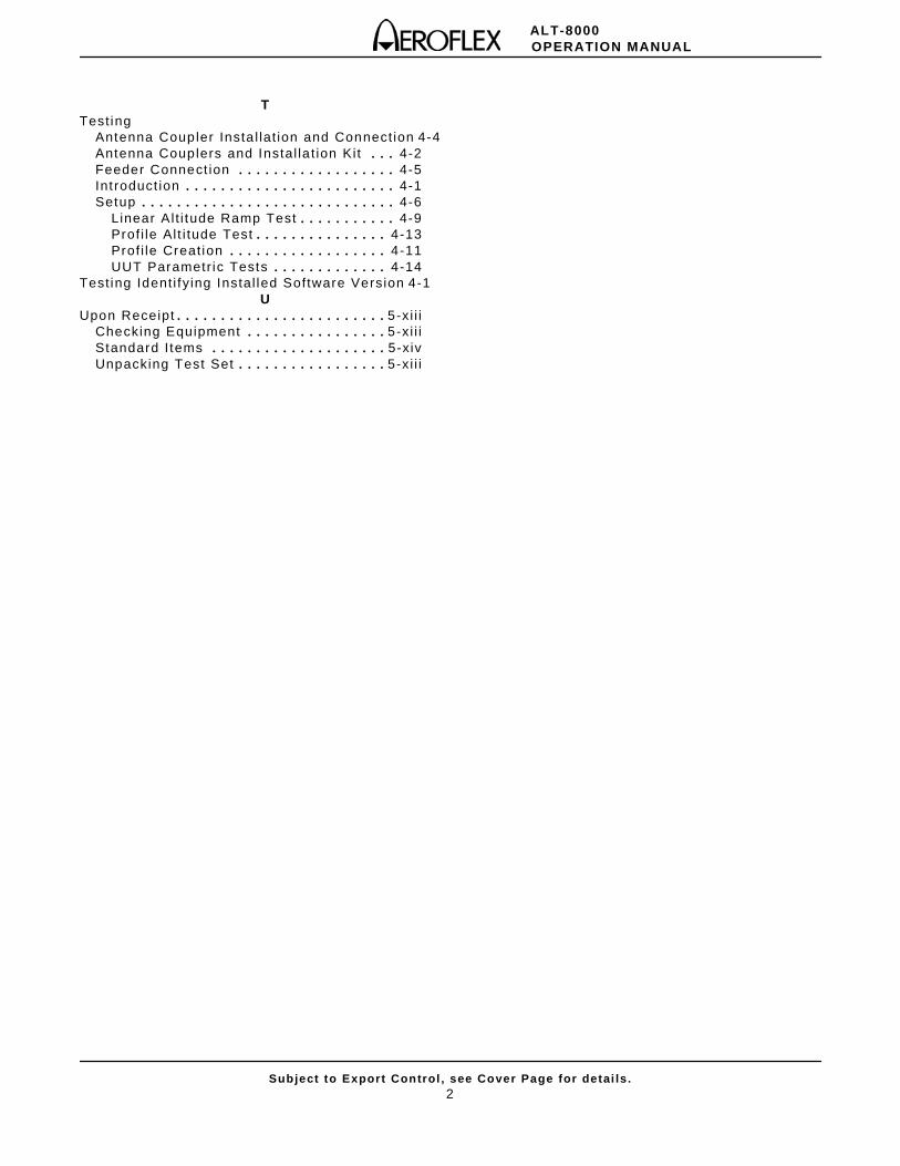
ALT-8000OPERATION MANUAL
Subject to Export Control , see Cover Page for detai ls .2
TTest ing
Antenna Coupler Insta l lat ion and Connect ion 4-4Antenna Couplers and Instal la t ion Kit . . . 4-2Feeder Connect ion . . . . . . . . . . . . . . . . . . 4-5Int roduct ion . . . . . . . . . . . . . . . . . . . . . . . . 4-1Setup . . . . . . . . . . . . . . . . . . . . . . . . . . . . . 4-6
Linear Al t i tude Ramp Test . . . . . . . . . . . 4-9Prof i le Al t i tude Test . . . . . . . . . . . . . . . 4-13Prof i le Creat ion . . . . . . . . . . . . . . . . . . 4-11UUT Parametr ic Tests . . . . . . . . . . . . . 4-14
Test ing Ident i fy ing Instal led Software Version 4-1U
Upon Receipt . . . . . . . . . . . . . . . . . . . . . . . . 5-xi i iChecking Equipment . . . . . . . . . . . . . . . . 5-xi i iStandard I tems . . . . . . . . . . . . . . . . . . . . 5-xivUnpacking Test Set . . . . . . . . . . . . . . . . . 5-xi i i

Our passion for performance is defined by threeattributes represented by these three icons:
solution-minded, performance-driven, customer-focused.
As we are always seeking to improve our products, the information in
this document gives only a general indication of the product capacity,
performance and suitability, none of which shall form part of any
contract. We reserve the right to make design changes without notice.
EXPORT CONTROL WARNING: This document contains controlled technology or technical data under the jurisdiction of the Export Administration Regulations (EAR), 15 CFR 730-774. It cannot be transferred to any foreign third party without the specific prior approval of the U.S. Department of Commerce Bureau of Industry and Security (BIS). Violations of these regulations are punishable by fine, imprisonment, or both.
CHINA / BeijingCHINA / Shanghai
FINLANDFRANCE
GERMANYHONG KONG
INDIAJAPANKOREA
SCANDINAVIA*SINGAPORE
UK / Cambridge*UK / Stevenage
*USA
Tel: [+86] (10) 6539 1166 Fax: [+86] (10) 6539 1778Tel: [+86] (21) 5109 5128 Fax: [+86] (21) 6457 7668Tel: [+358] (9) 2709 5541 Fax: [+358] (9) 804 2441Tel: [+33] 1 60 79 96 00 Fax: [+33] 1 60 77 69 22Tel: [+49] 8131 2926-0 Fax: [+49] 8131 2926-130Tel: [+852] 2832 7988 Fax: [+852] 2834 5364 Tel: [+91] (0) 80 4115 4501 Fax: [+91] (0) 80 4115 4502Tel: [+81] 3 3500 5591 Fax: [+81] 3 3500 5592Tel: [+82] (2) 3424 2719 Fax: [+82] (2) 3424 8620Tel: [+45] 9614 0045 Fax: [+45] 9614 0047Tel: [+65] 6873 0991 Fax: [+65] 6873 0992Tel: [+44] (0) 1763 262277 Fax: [+44] (0) 1763 285353Tel: [+44] (0) 1438 742200 Fax: [+44] (0) 1438 727601Freephone: 0800 282388 Tel: [+1] (316) 522 4981 Fax: [+1] (316) 522 1360Toll Free: 800 835 2352
* Indicates Regional Sales/Service Center