Embed Size (px)
Citation preview

ALST IMGRUAU P.TSDMF 07-018 D30/05/2007Non-Proprietary Version
Page:1/17
UNISTAR PROJECT
TURBINE MISSILE ANALYSIS
I SummaryThis report describes ALSTOM Power's method for the determination of the turbine missile generationprobability P(T) for LP (Low Pressure) and HIP (High Intermediate Pressure) rotors in nuclear powerplants.The dominant mechanism is assumed to be stress corrosion cracking (SCC).The probability of a rotor failure due to SCC consists of the probability of crack initiation and theprobability of crack growth up to the critical crack size.The analysis carried out for the UNISTAR preliminary design of the LP and HIP rotors, shows a veryfavorable low probability of missile generation. The main reasons are:
* ALSTOM Power have not experienced any cracks in any rotor of welded construction in therelevant radial-axial plane where they might have the potential to develop and release amissile
* Use of rotor material with a high resistance toS'C initiation and growth* Low stresses at the locations where SCC cracks could initiate.
For the LP and HIP rotors, the cumulative probability of missile generation over the time has beencomputed considering the "worst" material pro9perties in the acceptance band (i.e. highest Rpo.2(68°F)= 102 ksi for LP rotors and 107 ksi for HIP rotor) and the unfavorably orientation of plant layout (i.e.the NCR value of 1.E5 has to be considered as minimum limit for missile generation probability). Itresulted that the maximum inspection interval that corresponds to the NRC specified probability, is18.1 years for the LP rotors and 21.3 years for the HIP rotor. Considering instead, the recommendedrotor inspection interval equal to 10 years of operation, the cumulative missile generation probability is1.0E6 and 0.9E 7 respectively for the LP and HIP rotors.
Distribution: AREVA - J. ROGE - G. FRANCONVILLE - M.C. MAENNEL - D. RIGOT - TSDMF2First issue I Modifications Date Author Approved
Author Approved A AREVA's comments taken into account 27-07-07 ROGE GRUAUDate 30-05-07 30-05-07 B AREVA's comments n* V0063 taken into account 28-09-07 ROGE GRUAU
Name GRUAU LAMARQUE C AREVA's comments n° V0064 taken into account 09-11-07 ROGE GRUAU
Visa D Update of the exhaust 05-12-07 ROGE GRUAU
© ALSTOM 2007. All rights reserved. Information contained in this document is provided without liability for information purposes only and is subject to change withoutnotice. No representation or warranty is given or to be implied as to the completeness of information or fitness for any particular purpose. Reproduction, use or disclosureto third parties, without express written authority, is strictly prohibited.

ALSTOMGRUAU P. Page:2/17TSDMF 07-018 D30/05/2007Non-Proprietary Version
2 Table of contents1 Summary 12 Table of contents 23 Summary of requirements of the U.S. Nuclear Regulatory Commission (NRC) 3
3.1 Introduction 33.2 Criteria that must be met to Demonstrate Compliance with Regulations 33.3 Procedure for Demonstrating Compliance with Regulations 3
4 Governing and overspeed protection systems 44.1 Description of the governing and overspeed protection systems 44.2 Recommended periodic tests in relation with governing system and overspeed protection _ 5
4.2.1 Overspeed protection system 54.2.2 Rotor couplings 5
5 Description of ALSTOM Power welded rotors 65.1 Welded Rotor Design_ 65.2 Description of Rotor Materials 75.3 Description of Temperature and Stress Distribution in UNISTAR LP-Rotor 85.4 Description of Stress Distribution in UNISTAR HIP-Rotor 9
6 Operating experience with welded LP rotors in nuclear power plants 97 Hypothetical failure modes of welded LP rotors 9
7.1 Failure Modes due to Stress Corrosion Cracking 97.1.1 Stress corrosion crack growth rate 97.1.2 Disc failure mode 107.1.3 Cracks without potential to release missile outside the casings 117.1.4 Cracks with potential to release missile outside the casings_ 11
7.2 Failure Modes due to Brittle Fracture 118 ALSTOM Power method for calculating turbine missile generation probability (P1) 11
8.1 Method for Calculating Turbine Missile Generation Probability (P1) due to SCC 118.1.1 Probability of Crack Initiation, q 128.1.2 Probability of Missile Generation of an Individual disc, p (T) 128.1.3 Computer Code 138.1.4 Overspeed 13
8.2 Determination of Inspection Intervals 148.3 Recommended Rotor Inspection 14
9 Results for UNISTAR Rotors__ 159.1 Program Input for LP rotor 15
9.1.1 Critical Crack Size ac 159.1.2 Crack Growth Rate r 159.1.3 Crack Initiation q and number of Individual Flows N 15
9.2 Program Input for the HIP rotor 159.2.1 Critical Crack Size ac 159.2.2 Crack Growth Rate r 159.2.3 Material Proof Strength 159.2.4 Crack Initiation q and number of Individual Flows N 15
9.3 UNISTAR Input Variables, Program Output and Inspection intervals for LP rotor 159.4 UNISTAR - Program Output and Inspection intervals for HIP rotor 16
10 List of Appendix 17
© ALSTOM 2007. All tights reserved. Information contained in this document is provided without liability for information purposes only and is subject to change withoutnotice. No representation or warranty is given or to be implied as to the completeness of information or fitness for any particular purpose. Reproduction, use or disclosureto third parties, without express written authotity, is strictly prohibited.

ALSTOMGRUAU P. Page:3/17TSDMF 07-018 D30/05/2007Non-Proprietary Version
3 Summary of requirements of the U.S. Nuclear Regulatory Commission (NRC)
3.1 IntroductionThe primary safety objective of the NRC is the prevention of unacceptable doses to the public from thereleases of radioactive contaminants that could be caused by damage to plant safety-relatedstructures, systems and components resulting from missile-generating turbine failures..
3.2 Criteria that must be met to Demonstrate Compliance with RegulationsAccording to General Design Criterion 4 of Appendix A to 10 Code of Federal Regulations Part 50,nuclear power plant structures, systems and components important to safety shall be appropriatelyprotected against dynamic effects, including the effects of missiles.Failures of the large steam turbines of the main turbine generator have the potential for ejecting largehigh-energy missiles that can damage plant structures, systems and components. The overall safetyobjective is to ensure that structures, systems and components important to safety are adequatelyprotected from potential turbine missiles.The probability of unacceptable damage resulting from turbine missiles (P4) is expressed as theproduct of:
" P1: the probability of turbine failure resulting in the ejection of turbine rotor (or inte'rnalstructure) fragments through the turbine casing;
* P2: the probability of ejected missiles perforating intervening barriers and striking safetyrelated structures, systems or components;
* P3: the probability of struck structures, systems or components failing to perform their safetyfunction.
According to NRC guidelines stated in Section 3.5.1.3 of the Standard Review Plan (NUREG-0800),and Regulatory Guide 1.115, the probability of unacceptable damage from turbine missiles should beless than or equal to about 1 chance in 10 million per year for an individual turbine unit, that is:P4 = P1 x P2 x P35 10-7 per unit per year.
3.3 Procedure for Demonstrating Compliance with Regulations
The present approach places on the applicant the responsibility for demonstrating and maintainingNRC-specified turbine reliability by appropriate in-service inspection and testing throughout plant life.The applicant show capability to have volumetric (ultrasonic) examinations performed which aresuitable for in-service inspection of turbine disks-and shaft and to provide reports for NRC review andapproval which describe his methods for determining turbine missile generation probabilities.Because of the uncertainties involved in calculating P2, the NRC concluded that P2 analyses are "BallPark" or "order of magnitude" only. On the basis of simple estimates for a variety of plant layouts, thestaff further concluded that the strike and damage probability product can be reasonably taken to fallin a characteristic narrow range which is dependent on the gross features of turbine generatororientation.
* For favorably oriented turbine generators, P2 x P3 tend to lie in the range 104 to 103.* For unfavorably oriented turbine generators, P2 x P3 tend to lie in the range 10-3 to 10,2.
For these reasons (and *because of inadequate data, controversial assumptions and modelingdifficulties) in the evaluation of P4, the NRC gives credit for the product of the strike and damageprobabilities (P2 x P3) of 10-3 for a favorably oriented plant layout and 10-2 for an unfavorably orientedplant layout and does not encourage calculations of them.The NRC safety objective with regard to turbine missiles is expressed in terms of two sets of criteriaapplied to the missile generation probability (P1), see Table 1.One set of criteria is to be applied to favorably oriented turbines, and the other is to be applied tounfavorably oriented turbines.Turbine manufacturers have to prepare reports describing their methods and procedures forcalculating turbine missile generation probabilities (P1) for review and acceptance by the NRC.Following the submittal of such reports to the NRC for review and approval, the manufacturer willprovide applicants and licensees with tables of missile generation probabilities versus time (in-servicevolumetric disk inspection interval for design speed failure and in-service valve testing interval fordestructive over speed failure) for their particular turbines, which are then to be used to establishinspection and test schedules which meet NRC safety objectives.
© ALSTOM 2007. All rights reserved. Information contained in this document is provided without liability for information purposes only and is subject to change withoutnotice. No representation or warranty is given or to be implied as to the completeness of information or fitness for any particular purpose. Reproduction, use or disclosureto third parties, without express written authority, is strictly prohibited.

A LST MGRUAU P. Page:4/17TSDMF 07-018 D30/05/2007Non-Proprietary VersionThis report considers possible failure modes at rated speed and at design overspeed. It has to bepointed out that the probability of failure at gross overspeed (and thus at destructive overspeed) islargely dictated by the probability of reaching gross overspeed, which is function of the governing andprotection system. This is dealt within Chapter 4 of the present document.
Probability [ per unit year ] Recommended licensee actionCase Favorably Unfavorably
oriented turbine oriented turbineA P1<104 P1<105 This-is the general, minimum reliability requirement for
loading the turbine and bringing the system on line.B 10-<P1<10- 10-<P1<104 If this condition is reached during operation, the
turbine may be kept in service until the next scheduleoutage, at which time the licensee must take action toreduce P1 to meet the appropriate A criterion beforereturning the turbine to service.
C 10"<<Pi<102 10-4 <P1<103 If this condition is reached during operation, theturbine is to be isolated from the steam supply within60 days, at which time the licensee is to take action toreduce P1 to meet the appropriate A criterion beforereturning the turbine to service.
D 10-2 <P1 102 <P1 If this condition is reached at any time duringoperation, the turbine must be isolated from the steamsupply within 6 days, at which time the licensee musttake action to reduce P1 to meet the appropriate Acriterion before returning the turbine to service.
Table 1: Turbine System Reliability Criteria
4 Governing and overspeed protection systems
4.1 Description of the governing and overspeed protection systemsThe probability of reaching destructive overspeed, i.e. the probability of releasing a missile, is largelydictated by the probability to have a failure of the governing and overspeed protection system. Thus,the shaft-lineoverspeed risk is the most important event taken into account in the turbine governingand protection strategy.Following topics are safety, oriented to match a probability of reaching an overspeed higher than 120%of the rated speed, better than 5x1 05 per year:
" Valve design:o Two independent valves in series on each steam inlet.o Steam inlet valve designed in order to reduce the efforts and avoid jamming risk.o Fail safe hydraulic actuators closing by mechanical spring.o Valve full stroke tests performed monthly.
• Speed governor design : ,o Speed governor reliability based on a duty stand-by controller and 3 speed sensors.o Speed governor is acting on the governing valves.o Speed sensor supervision.o Speed limiter at 107 %, within governing system.o Acceleration limiter and power unbalance function, within governing system.
* Protection system design :o Independent protection system, failsafe, acting on all the steam inlet valves.o Triple redundant overspeed protection with SIL3 certification according to IEC61508
standard. Io First and second overspeed protections made with different technologies.o Protection system action and tripping capability test, performed daily, in an automatic
way.
© ALSTOM 2007. All rights reserved. Information contained in this document is provided without liabiiity for information purposes only and is subject to change withoutnotice. No representation or warranty is given or to be implied as to the completeness of information or fitness for any particular purpose. Reproduction, use or disclosureto third parties, without express wdtten authority, is strictly prohibited.

ALSTOMGRUAU P. Page:5/17TSDMF 07-018 D30/05/2007Non-Proprietary Version
0 Reverse power relay:o Reverse power relay used to keep the circuit breaker closed, as long as the
mechanical power is not cancelled.
4.2 Recommended periodic tests in relation with governing system and overspeedprotection
4.2.1 Overspeed protection system
The probability to have a failure of the governing and overspeed protection system is linked to the in-service inspections and exercising intervals.The recommended inspection and exercising of turbine valves and protection system are:
* At each refueling, (does not require any dismantling):o HP stop valve tightness tested.o Valve and servomotor assembly behavior checked : travel time, stroke and travel
effort.o Hydraulic protection circuit functional tested.
* During each refueling, one of the valves is inspectedo Visual and surface examinations (seats, stems and internal part of the HP valves,
bearings and sealings of the IP valves).* On load tests :
o Overspeed system and Hydraulic trip block tested daily (in an automatic way).o Valves full stroke test : monthly for each valve (it is recommended that this test will be
preceded by a limitation at 97% load in order to anticipate this load reductionassociated with one valve closing).
o Extraction non-return valve : power closing assistance checked.
4.2.2 Rotor couplingsSince a rupture of the couplings between the turbine rotors participates in thý probability of reachingdestructive overspeed, the coupling bodies and coupling bolts are inspected during each fullmaintenance overhaul, i.e. about every 10 years.
C ALSTOM 2007. All rights reserved. Information contained in this document is provided without liability for information purposes only and is subject to change withoutnotice. No representation or warranty is given or to be implied as to the completeness of information or fitness for any particular purpose. Reproduction, use or disclosureto third parties, without express written authority, is strctly prohibited.

ALSTOMGRUAU P.TSDMF 07-018 D30/05/2007Non-Proprietary Version
Page:6/17
5 Description of ALSTOM Power welded rotors
5.1 Welded Rotor DesignThe rotor design used by ALSTOM Power for large LP (Low Pressure) and HIP (High IntermediatePressure) rotors is the welded type : 9 welds for the LP rotor and 3 welds for the HIP rotor (HP in oneforged part and IP in 3 forged parts). Figure 1 shows a cross section of a LP rotor. Figure 2 shows across section of a HIP rotor.
Figure 1 : Cross section of the welded LP rotor for UNISTAR
© ALSTOM 2007. All rights reserved. Information contained in this document is provided without liability for information purposes only and is subject to change withoutnotice. No representation or warranty is given or to be implied as to the completeness of information or fitness for any particular purpose. Reproduction, use or disclosureto third parties, without express written authority, is strictly prohibited.
ALSTOMGRUAU P. Page:7/17TSDMF 07-018 D30/05/2007Non-Proprietary Version
JI Rvfu~~~d ",''"S,'. .
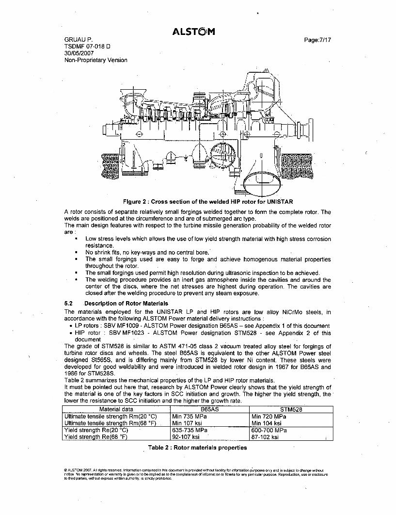
Figure 2 Cross section of the welded HIP rotor for UNISTAR
A rotor consists of separate relatively small forgings welded together to form the complete rotor. Thewelds are positioned at the circumference and are of submerged arc type.The main design features with respect to the turbine missile generation probability of the welded rotorare:
• Low stress levels which allows the use of low yield strength material with high stress corrosionresistance.
* No shrink fits, no key-ways and no central bore.* The small forgings used are easy to forge and achieve homogenous material properties
throughout the rotor.* The small forgings used permit high resolution during ultrasonic inspection to be achieved.* The welding procedure provides an inert gas atmosphere inside the cavities and around the
center of the discs, where the net stresses are highest during operation. The cavities areclosed after the welding procedure to prevent any steam exposure.
5.2 Description of Rotor MaterialsThe materials employed for the UNISTAR LP and HIP rotors are low alloy NiCrMo steels, inaccordance with the following ALSTOM Power material delivery instructions :
" LP rotors : SBV MF1009 - ALSTOM Power designation B65AS - see Appendix 1 of this document* HIP rotor : SBV MF1023 - ALSTOM Power designation STM528 - see Appendix 2 of this
document -
The grade of STM528 is similar to ASTM 471-05 class 2 vacuum treated alloy steel for forgings ofturbine rotor discs and wheels. The steel B65AS is equivalent to the other ALSTOM Power steeldesigned St565S, and is differing mainly from STM528 by lower Ni content. These steels weredeveloped for good weldability and were introduced in Welded rotor design in 1967 for B65AS and1986 for STM528S.'Table 2 summarizes the mechanical properties of the LP and HIP rotor materials.It must be pointed out here that, research by ALSTOM Power clearly shows that the yield strength ofthe material is one of the key factors in SCC initiation and growth. The higher the yield strength, thelower the resistance to SCC initiation and the higher the growth rate.
Material data B65AS STM528Ultimate tensile strength Rm(20 0C) Min 735 MPa Min 720 MPaUltimate-tensile strength Rm(68 OF) Min 107 ksi Min 104 ksiYield strength Re(20 0C) 635-735 MPa 600-700 MPaYield strength Re(68 *F) 92-107 ksi 87-102 ksi
Table 2: Rotor materials properties
© ALSTOM 2007. All rights reserved. Information contained in this document is provided without liability for information purposes only and is subject to change withoutnotice. No representation or warranty is given or to be implied as to the completeness of information or fitness for any particular purpose. Reproduction, use or disclosureto third parties, without express written authority, is strictly prohibited.
ALSTOMGRUAU P. Page:8/17TSDMF 07-018 D30/05/2007Non-Proprietary VersionThe absorbed impact energy at room temperature is specified to be higher than 81J (see Appendix 1and 2). The fracture appearance transition temperature FATT50 and the fracture toughness (KIC) aredetermined as indicated in Appendix 3. Hence the minimund possible fracture toughness KIc at 20'C(68°F) equals KIC(B&L) at FATT5, i.e. 160 ksNin for the LP rotors and 155 ksirin for the HIP rotor.
5.3 Description of Temperature and Stress Distribution in UNISTAR LP-Rotor
[Proprietary]
© ALSTOM 2007. All rights reserved. Information contained in this document is provided without liability for information purposes only and is subject to change withoutnotice. No representation or warranty is given or to be implied as to the completeness of information or fitness for any particular purpose. Reproduction, use or disclosureto third parties, without express written authority, is strictly prohibited.

ALSTOMGRUAU P.TSDMF 07-018 D30/05/2007Non-Proprietary Version
Page:9/17
5.4 Description of Stress Distribution in UNISTAR HIP-Rotor
[Proprietary]
6 Operating experience with welded LP rotors in nuclear power plants,
The first turbine generator in a nuclear power plant with welded LP rotors went into service in 1965. Atthe end of 2004 there were 277 ALSTOM Power welded LP rotors in operation in nuclear powerplants. To date there have been no reports of rotor failures and no indications of stress corrosioncracking in the relevant radial-axial plane where they could extend to release a missile. The averageoperating hours of welded LP rotors, which have been in service for more than 3 years, is greater than90'000 hours.
7 Hypothetical failure modes of welded LP rotors
As described in 6 there have been no failures of ALSTOM Power welded LP rotors in nuclear powerplants up to now. Therefore the discussion of failure modes is purely hypothetical.Based on the experience of stress corrosion cracking (SCC) in LP rotors of the shrunk on disc design,failures due to this type of cracking will be discussed as well as failures due to brittle fracture.
7.1 Failure Modes due to Stress Corrosion Cracking
7.1.1 Stress corrosion crack growth rate
Stress corrosion cracking in LP rotors is most likely to occur in the early wet stages, i.e. the region justafter the Wilson-Line. As a conservative assumption, it is assumed that a stress corrosion crack caninitiate not only in this area but also in every HP stages.The propagation rate of stress corrosion cracks in steam turbine rotor steels depends on the appliedstress intensity. An example for a similar material is illustrated in Figure 3.
© ALSTOM 2007. All rights reserved. Information contained in this document is provided without liability for information purposes only and is subject to change withoutnotice. No representation or warranty is given or to be implied as to the completeness of information or fitness for any particular purpose. Reproduction, use or disclosureto third parties, without express written authority, is strictly prohibited.

ALSTOMGRUAU P.TSDMF 07-018 D30/05/2007Non-Proprietary Version
Page:10/17
stress intensity. K, [ka iYinT I
1s a 20 40 60 80 10010 t i
E
o
0
U
'0
101
105
id,
intergranular stress corrosion cracking
steam turbine rotor steel 26NiCrMoV 12 7(A47 1)
H 2 0. 100*C (212*F), deaerated
42
TYS. R PO.2= 1220MN/m2= 177ksi•
A -17s
w YS . O2 1 M
M 1i i , i 2
1000
ptoo <
10
-1.0
001 0
0
0
01
1-
1610
1i511 1-
-(12
0 K 20 40 60 80 100 12'ISCcstress intensity, K, IMN-m-3/2
Figure 3 : Effect of stress intensity and yield strength on crack growth rate
At very low stress intensities, close to the threshold stress intensity KISCC, cracks grow slowly i.e.slower than 10-1r m/sec. As the stress intensity increases from KISCC the stress corrosion crackgrowth rate increases until a plateau is reached where the crack growth rate no longer depends on thestress intensity over a wide range of stress intensity. This "plateau" crack growth rate depends onvarious influences, for example on the yield strength of the steel. At higher stress intensities, a furtheracceleration of stress corrosion cracks growth is observed, but this is not well documented. Availablestress corrosion crack growth data indicates that the plateau range extends to at least KI = 100 ksi'/in.With respect to possible failure modes, this means that once a crack is initiated it will grow in a stablemanner until the crack size reaches a value corresponding to at least 100 ksi'!in.
7.1.2 Disc failure mode
In the case of a welded rotor, a crack with the potential to release missiles must develop in an axial-radial plane. The maximum principal stress, which is the crack driving stress, is the circumferentialstress (see Figure 4).
Figure 4: Hypothetical failure mode of welded LP-rotor due to SCC
© ALSTOM 2007 All rights reserved Inforrmation contained in this document is provided without liability for information purposes only and is subject to change withoutnotice. No representation or warranty is given or to be implied as to the completeness of information or fitness for any particular purpose Reproduction, use or disclosureto third parties, without express written authority, is stricty prohibited.

ALSTOMGRUAU P. Page: 11/17TSDMF 07-018 D30/05/2007Non-Proprietary Version
[Proprietary]
7.1.3 Cracks without potential to release missile outside the casings
[Proprietary]
7.1.4 Cracks with potential to release missile outside the casings
[Proprietary]
7.2 Failure Modes due to Brittle FractureA failure as a result of a brittle fracture in a LP or HIP rotor may occur during a cold start or anunforeseen over speed. The prerequisite of such an event is an existing flaw or crack inside the rotorreaching the critical crack size during operation.ALSTOM Power assures by stringent requirements on the conditions of forgings for welded rotors thatthe discs do not have pre-existing flaws or inclusions of unacceptable size (see Delivery InstructionETL-EP-MAT 07-005 in Appendix 4).As mentioned in 5.2, the fracture toughness of the LP and HIP rotor materials are at least respectively160 ksi/in and 155 ksi'/in at a temperature of 20 0C. According to NRC requirements, the ratio betweenfracture toughness and the maximum circumferential stress at design over speed (120% of the normaloperating speed) shall exceed the value 2'!in. The maximum stress in the LP rotor amounts to:
[Proprietary]
From these facts it can be concluded that a failure due to cyclic loading and brittle fracture is muchmore unlikely than a failure due to SCC.
8 ALSTOM Power method for calculating turbine missile generation probability(P1)
The missile generation probability of a turbine (P1) consists of two factors:* P1' : the probability of rotor failure producing an internal turbine missile.* P1" : the probability that this internal missile penetrates the casings and is ejected from the
turbine.Summarizing : P1 = P1' x P1" rThe probability P1' can be determined by means of fracture mechanics, considering as probabilisticquantities the variables involved in the evaluation such as critical crack sizes, crack growth rates,stresses and temperatures. These properties and details are well documented in the case of turbinerotors.The procedures for estimating P1" are not as sophisticated as the procedures for calculating P1'. Theusual method is to compare the kinetic energy of a potential internal turbine missile with the energynecessary to perforate the turbine casing. The result of such an estimation will be either P1" = 0 or P1"= 1.0.ALSTOM Power conservatively assumes P1" to be equal to one (1.0). This means the turbine missilegeneration probability equals the internal turbine missile generation probability : P1 = P1' (for both LPand HIP modules).
8.1 Method for Calculating Turbine Missile Generation Probability (P1) due to SCCAccording to the present knowledge on SCC phenomena, three ranges have to be distinguished:(1) Crack Initiation or Incubation Phase : it is commonly accepted that a threshold value KISCCexists. If the stress intensity KI is below this threshold, SCC is not expected.(2) Constant Crack Growth Rate : if the stress intensity KI exceeds the threshold value KISCC thecrack growth rate remains constant on a certain plateau-value for quite a large range of KI.
© ALSTOM 2007. All rights reserved.,Information contained in this document is provided without liability for information purposes only and is subject to change withoutnotice. No representation or warranty is given or to be implied as to the completeness of information or fitness for any particular purpose. Reproduction, use or disclosureto third parties, without express written authority, is strictly prohibited.

ALSTOMGRUAU P. Page:12/17TSDMF 07-018 D30/05/2007Non-Proprietary Version(3) Accelerated Crack Growth Rate, Critical Crack Size: if KI exceeds a certain amount, theassumption of a constant plateau-value is no longer valid. Available data indicate that the plateaurange extends to at least 100 ksi'/in, see also Figure 3.It should be pointed out that this value is lower than the minimum specified fracture toughness of theUNISTAR LP and HIP rotor forgings (KIC =155 ksi4in), see 5.2).In order to obtain results lying on the safe side, ALSTOM Power uses the plateau limit value KIP = 100ksi'/in for the determination of the critical crack sizes, i.e. the calculation is stopped when the crackgrowth reaches the end of the plateau.As a conservative assumption, it will be considered that an SCC crack could appear in any blade pin-root attachment operating in wet steam, i.e. discs 2 and 3 of LP rotor and all the HP discs of the HIProtor.The probability of generating a missile (P1) under the conservative assumption P1 = P', which wasexplained previously, is computed as a function of time as follows:
N
P (T) pi p(T).q1, valid for p, -q, 1<< Eq I1 i=t
Where:N Number of discs in the unit, susceptible to SCC initiationT Time in operating yearspi(T) Probability of missile generation in an individual disc.qi Probability of crack initiation in an individual disc.Due to the fact that the ALSTOM LP rotors in a unit have the same design and any crack will initiate atthe same location, Eq 1 can be rewritten as.:
P1(T)=N.p(T).q Eq2where NN = Number of LP flows in the case of the LP discsN = 1 in the case of the HP discs
8.1.1 Probability of Crack Initiation, q
[Proprietary]
8.1.2 Probability of Missile Generation of an Individual disc, p (T)
[Proprietary]
8.1.2.1 Critical Crack Size, ac
The critical crack size ac for a semi-elliptical surface crack is given by:
a'=G. KI [in] Eq 31.21.
Where:G Flaw geometry factorKIC Fracture toughnessCa Operational net stress at nominal speed.Generally G, KIC and a are uniformly distributed variables. With respect to this, the followingassumptions are made:
8.1.2.2 Flaw Geometry Factor G
G is a uniformly distributed variable ranging from 1.0 to 1.5. Hence, the mean is G = 1.25 and thestandard deviation is SG = 0.144.
© ALSTOM 2007. All rights reserved. Information contained in this document is provided without liability for information purposes only and is subject to change withoutnotice. No representation or warranty is given or to be implied as to the completeness of information or fitness for any particular purpose. Reproduction, use or disclosureto third parties, without express written authority, is strictly prohibited.

ALSTOMGRUAU P. Page:13/17TSDMF 07-018 D30/05/2007Non-Proprietary Version8.1.2.3 Fracture Toughness KIC
The plateau values of the constant crack growth rate are only established properly to an upper limit ofstress intensity KIP = 100 ksilin. The available test results are not sufficient to perform a statisticalanalysis with respect to the scattering of this plateau limit.Laboratory tests performed by ALSTOM Power indicate that the assumed limit KIP = 100 ksi'/in is areasonable conservative value. Furthermore, it is considerably lower than the minimum fracturetoughness of the UNISTAR LP and HIP rotors (respectively 160 ksi'/in and 155 ksi'/in).For these reasons, the conservative value of KIP = 100,ksi'/in is taken as a constant and not a randomvariable.
8.1.2.4 Operational Net Stress
[Proprietary]
The influence of design over speed is not taken into consideration, because these events are very fewand have a short duration, so that the effect on crack propagation from SCC can be neglected.Due to the fact that all stresses and temperatures are calculated by the Finite Element Method, arelative standard deviation Sala = + 5 % is realistic, and a is assumed to be normal distributed.
8.1.2.5 [Proprietary]
[Proprietary]
8.1.2.6 Distribution of Sac
The distribution of ac is calculated by means of Equation 8 and according to the distribution of itsparameters G and a.
8.1.3 Computer Code
The procedure described above was computerized by ALSTOM Power.The program calculates the probability for an individual LP flow p(T), and generates a plot showing thetotal probability P1 (T) according to Eq 3 for a given turbine generator versus operating years.
8.1.4 OverspeedThe critical crack size was determined with the nominal operating stress and a fracture toughness ofKIC = KIP = 100 ksi'/in.The risk of rotor fracture at design over speed is incorporated within the risk of fracture at normalspeed. This is the result of considerable conservatism in the assessment of risk of fracture at normalspeed. As discussed in 7.1, it is well established that the rate of stress corrosion crack growth isinsensitive to the crack stress intensity and hence, under constant stress, is insensitive to crack size.But this only applies up to a certain level of stress intensity, beyond which crack growth accelerates. Itis a convenient simplification to assume that crack growth at normal rotor speed continues at a uniformrate until it reaches the point of acceleration, at a stress intensity of 100 ksi'lin,.where after it is veryconservatively assumed to progress at such a rapid rate as to lead almost immediately to fracture.It follows that only cracks growing at normal rotor speed to stress intensities lower than 100 ksi'/incould be the cause of fracture at overspeed.For a design overspeed of e.g. 120% of normal speed, the crack stress intensity of 100 ksi'/in atnormal speed rises to 1.20 2xl00 ksi4in = 144 ksibin, which is lower than the lowest specified fracturetoughness UNISTAR LP and HIP rotor forgings (respectively 160 ksiin and 155 ksi'iin). Therefore anycrack that might possibly lead to fracture at design over speed has already been conservativelyassumed to cause fracture at normal speed, and must not be counted a second time in the evaluationof fracture probability.In case the LP rotor will reach burst speed (i.e. > 150%), it will burst irrespective of whether crackshave previously developed within it. Thus the probability of missile release at burst speed is equal tothe probability of the burst speed occurring. Burst speed, owing to failure of the control & protectionsystem and leading to rotor bursting has not been computed.
© ALSTOM 2007. All rights reserved. Information contained in this document is provided without liability for information purposes only and is subject to change withoutnotice. No representation or warranty is given or to be implied as to the completeness of information or fitness for any particular purpose. Reproduction, use or disclosureto third parties, without express written authority, is strictly prohibited.

ALSTOMGRUAU P. Page:14/17TSDMF 07-018 D30/05/2007Non-Proprietary Version8.2 Determination of Inspection IntervalsThe maximum allowable inspection intervals are determined by evaluating the results for the turbinemissile generation probability P1(T) for the individual turbine generator.According to the NRC requirements given in 3.3, the limit for P1(T) will be either 10 '4 for favorablyoriented plants or 10-' for unfavorably oriented plants. For UNISTAR the unfavorably oriented plant willbe considered and therefore a limit of 10-5 applies.In the inspection and overhaul plans, ALSTOM Power recommends major rotor inspection intervals of10 years for plants that are maintained in accordance with the typical recommended proceduresprovided in Figure 5 (note that this procedure has to be adapted to the refueling schedule forUNISTAR).Aim of the analysis is to demonstrate that the risk of missile generation due to stress corrosioncracking is completely covered by the usual inspection programs and no additional measures have tobe introduced to meet the NRC missile probability limit.
Maintenance Type C P R P R P D P P R P R P DHP-IP module Xl X1LP1 module X2 - -X2
LP2 module X2 - X2LP3 module X2 X2Maintenance Type P[P R P RP 0 P P R P R PHP-IP module X1 X1LP1 module X2 __ X2LP2 module X2 - X2LP3 module X2 X2Maintenance Type P P R P RP D P P R P R PHP-IP module Xl X1LP1 module X2 - - X2LP2 module X2 - X2LP3 module X2 I X2 I t
In generall X Full maintenance overhaulHP-IP module xLJJPartial maintenance overhaul
LP module= [2 Partial maintenance overhaul to check last blades and rubber 0 nngs
E ]First Contractual Overhaul
SPartial OverhaulWMaintenance during Refueling
1 10 years Global Maintenance
Figure 5 : Recommendations for inspection intervals of large turbine generators
8.3 Recommended Rotor Inspection
[ Proprietary]
The recommended inspection requirements for LP rotors during major overhauls ensures that anyindications of SCC will be detected. The inspection includes a thorough visual inspection for erosionand corrosion and magnetic particle examination at selected areas to detect any cracking at the rotorsurfaces. In the very unlikely event of surface indications being detected, additional ultrasonicexaminations will be performed.A complete volumetric ultrasonic inspection for SCC is not necessary in the case of welded rotors.
0 ALSTOM 2007 All rights reserved Information contained in this document is provided without liability for information purposes only and is subject to change withoutnotice No representation or warranty is given or to be implied as to the completeness of information or fitness for any particular purpose Reproduction use or disclosureto third parties, without express written authority, is strictly prohibited

ALST OMGRUAU P. Page:15/17TSDMF 07-018 D30/05/2007Non-Proprietary Version
9 Results for UNISTAR Rotors
9.1 Program Input for LP rotor
9.1.1 Critical Crack Size ac
[ Proprietary]
9.1.2 Crack Growth Rate r
[Proprietary]
9.1 3 Crack Initiation q and number of Individual Flows N
[Proprietary]
9.2 Program Input for the HIP rotor
9.2.1 Critical Crack Size ac
[Proprietary]
9.2.2 Crack Growth Rate r
Mean value r (see 8.1.2.1 Erreur 1 Source du renvoi introuvable.)Sr = 0.587 (see 8.1.2.1).Tc (see 8.1.2.1) : the mean temperature in the discs was considered to compute thecrack growth rate.
9.2.3 Material Proof Strength
A worst case Missile Analysis was carried out for UNISTAR HIP rotors, which is based on themaximum proof strength specified for the material forgings where SCC could occur (i.e.Rp0.2(68*F)=700 MPa, 102 ksi).
9.2.4 Crack Initiation q and number of Individual Flows N
[Proprietary]
9.3 UNISTAR Input Variables, Program Output and Inspection intervals for LP rotorThe input variables for the worst case which is the discs 3 of the LP rotors of UNISTAR aresummarized in Table 3.
[Proprietary]
Table 3 Input data for the Missile Analysis Program
As a result of the computation, the cumulative probability (P1) is plotted versus service life (years) forthe disc 3LP and for N = 6. As UNISTAR LP rotors could be unfavorably oriented, le-5 figure has tobe taken as minimum limit (see 3.3, Table 1).
© ALSTOM 2007. All rights reserved. Information contained in this document is provided without liability for information purposes only and is subject to change withoutnotice. No representation or warranty is given or to be implied as to the completeness of information or fitness for any particular purpose. Reproduction, use or disclosureto third parties, without express wrtten authority, is strictly prohibited.

ALSTOMGRUAU P.TSDMF 07-018 D30/05/2007Non-Proprietary Version
Page:16/17
[Proprietary]
Figure 6 : LP rotor of UNISTAR: Probability P1(T) vs. time (years), 3LP discs
With the same process as for the 3LP, the cumulative probability (P1) is plotted versus service life(years) forthe disc 2LP and for N = 6. Furthermore, the sum of P1(T) for 2LP and 3LP is plotted.
[Proprietary]
Figure 7 : LP rotor of UNISTAR: Probability PI(T),vs. time (years), 2 & 3LP discs
As shown in Figure 7, 18.1 years is the maximum inspection interval for UNISTAR LP rotors thatcorresponds to the NRC specified probability of 105 . The maximum inspection interval associated witha probability of 10-4 is 32.8 years. When considering 10 years of operation instead of probability of 10-4
or 105 , the cumulative missile generation probability is 1.0E6.
9.4 UNISTAR - Program Output and Inspection intervals for HIP rotor
As a result of the computation, the cumulative probability (P1) is plotted versus service life (years) forall the individual HP discs from 1HP to 8HP. Furthermore, the sum ofP1l(T) for 1HP to 8HP is plotted.As UNISTAR HIP rotors could be unfavorably oriented, 10-5 figure has to be taken as minimum limit(see 3.3, Table 1). -
[Proprietary]
Figure 8 : HIP rotor of UNISTAR: Probability P1(T) vs. time (years), I to 8HP discs
As shown in Figure 8, 21.3 years is the maximum inspection interval for UNISTAR HIP rotors thatcorresponds to the NRC specified probability of 10-5 . The maximum inspection interval associated witha probability of 10-4 is 34.5 years. When considering 10 years of operation instead of probability of 10-4
or 105 the cumulative missile generation probability is 0.9E 7 .
© ALSTOM 2007, All rights reserved. Information contained in this document is provided without liability for information purposes only and is subject to change withoutnotice. No representation or warranty is given or to be implied as to the completeness of information or fitness for any particular purpose. Reproduction, use or disclosureto third parties, without express written authority, is strictly prohibited.

ALSTOMGRUAU P. Page:17/17TSDMF 07-018 D30/05/2007Non-Proprietary Version
10 List of Appendix
Appendix I ETL-EP-MAT 07-003: Rotor forgings in B65A-S for nuclearsteam turbine
Appendix 2 ETL-EP-MAT 07-004: Rotor forgings in STM528 for nuclearsteam turbine
Appendix 3 HZLM 620206 : Test Instructions - Determination of Kic acc. toBegley and Logsdon
Appendix 4 ETL-EP-MAT 07-005: Inspection for internal defects -Ultrasonic examination
© ALSTOM 2007. All rights reserved. Information contained in this document is provided without liability for information purposes only and is subject to change withoutnotice. No representation or warranty is given or to be implied as to the completeness of information or fitness for any particular purpose. Reproduction, use or disclosureto third parties, without express written authority, is strictly prohibited.

ALST, M ALSTOM Power IETL- EP- MAT 07- 003D6partement responsable: Ddpartement destinataire: Rdvision: Type doe: No fichlor:
9010 A NDCr,6: VWrifi: Approuv6: Langue: Page:
2007-05-16 MA MOREAUX 2007-05-16 J ROGE 2007-05-16 MC MAENNEL En 1/2Domaine d'appllcatlon: Doc.d'orlgine: Remplace: No classification:
Rotor forgings in B65A-S for nuclear steam turbine
1. Scope
The present instruction applies to forged pieces for turbine rotors made of B65A-S. This instructionsummarizes the requirements concerning mechanical properties of rotor forgings specified in the deliv-ery instruction SBV MF1009.If the value in the delivery instruction SBV M1009 deviates from the values indicated in the present in-struction, the requirements of the latter will apply.
2. Tests
The following requirements, as stated in the delivery instruction SBV MF1009, must be verified:
2.1 Tensile properties at room temperature
Each welded rotor consists of several shaft parts (forgings). The requested yield and tensile strengthvalues are specified hereafter:
MPa (ksi)
Rm Ultimate tensile strength _> 735 (_ 106,6)
Re Yield strength or 0,2% proof strength 635 - 735 (92 - 106,6)
2.2 Notched - bar impact test at room temperature (minimum operating temperature)
J (ftlb)
AKV (ISO-V) _81 (Ž60)
2.3 Toughness determination
2.3.1 FATT 50
The FATT 50 value shall be determined according to ASTM A 370. The determined FATT 50 shall notbe higher than -1 8°C (00F).
'Ce document, prpriotd exclusive de notre SociWt6, est strictement confidentiel. lI ne peut 6tre communiqu6, copi6 ou reproduit sans son auto-risation 6crite. © ALSTOM 2007

SRevision: Langue: Page:
A en 2/2
2.3.2 Fracture toughness atroom temperature
This examination has only to be performed if requested in the I&T plan. The Kjc value shall be esti-mated from tangential oriented tensile and Charpy - V specimens from the outer test ring using theBegley and Logsdon method (according .to instruction HZLM 620206). The estimated Kjc value is forinformation only.
2.4 Other requirements
For the other requirements the material delivery instruction SBV MF1009 shall apply. The tests shall becarried out according to the instructions SBV MF2002 and SBV MF2004.
3. Documentation
The requested test values 2.1 to 2.3.2 must be stated in the test certificate.
4. Reference documents
SBV MF1009
SBV MF2002
SBV MF2004
HZLM 620206
Material specification B 65 A-S steel
Product general technical specification low-alloy stell forgings for components ofwelded rotors for steam turbines
Particular technical specification of part - Low-alloy steel forgings for compo-nents of welded rotors for steam turbines
Determination of KIC cc. to Begley and Logsdon

ALSTOM F ALSTOM Power -FETL-EP-MAT 07-004Dpartemnent responsable: Ddpartemnent destinatalre: R6 Islon: Type doc: No flohler:
9010 ACr6: V~dflf: Approuv: Langue: Page:
2007-05-16 MA MOREAUX 2007-05-16 J ROGE 2007-05-16 MC MAENNEL en 1/2Dornaine d'application: Doc.d'origlne: Remplace: No classification:
Rotor forgings in STM 528 for nuclear steam turbine
1. Scope
The present instruction applies to forged pieces for turbine rotors made of STM 528. This instructionsummarizes the requirements concerning mechanical properties of rotor forgings specified in the deliv-ery instruction SBV MF1023.If the value in the delivery instruction SBV M1023 deviates from the values indicated in the present in-struction, the requirements of the latterwill apply.
2. Tests
The following requirements, as stated in the delivery instruction SBV MF1023, must be verified:
2.1 Tensile properties at room temperature
Each welded rotor consists of several shaft parts (forgings). The requested yield and tensile strengthvalues obtained after post-welding heat treatment are specified hereafter:
MPa (ksi)
Rm Ultimate tensile strength >_ 720 (> 104,2)
Re Yield strength or 0,2% proof 600-700 (87-101,5).strength 600_ -_700 (_87_-_10__,5)
2.2 Notched - impact test at room temperature (minimum operating temperature)
The following values shall be verified after post-welding heat treatment:
J (ftlb)
AKV (ISO-V) transversal _ 81 (Ž 60)
2.3 Toughness determination
2.3.1 FATT 50
The FATT 50 value shall be determined according to ASTM A 370. The determined FATT 50 shall notbe higher than -30 0C (-22 0 F).
Ce document, propriWt6 exclusive de notre Soci&t6, est strictement confidentiel. II ne peut 6tre communiqu6, copi6 ou reproduit sans son auto-risation 6crite. © ALSTOM 2007

R 1v1sio n : L a n g ue : P a g e : E 0ALSTOM ETL-EP-MAT 07-004
2.3.2 Fracture toughness at room temperature
This examination has only to be performed if requested in the I&T plan. The Kjc value shall be esti-mated from tangential oriented tensile and Charpy - V specimens from the outer test ring using theBegley and Logsdon method (according to instruction HZLM 620206). The estimated Kjc value is forinformation only.
2.4 Other requirements
For the other requirements the material delivery instruction SBV MF1023 shall apply. The tests shall becarried out according to the instructions SBV MF2004, SBV MF2002, SBV MF2001 and SBV MF2005.
3. Documentation
The requested test values 2.1 to 2.3.2 must be stated in the test certificate.
4. Reference documents
SBV MF1023 Material specification STM 528 steel
SBV MF2002 Product general technical specification low-alloy stell forgings for components ofwelded rotors for steam turbines
SBV MF2004 Particular technical specification of part - Low-alloy steel forgings for compo-nents of welded rotors for steam turbines
SBV MF2001 Product general technical specification low-alloy steel forgings for monobloc ro-tors for steam turbines
SBV MF2005 Particular technical specification of part - Low-alloy steel forgings for steam tur-bine welded rotors service temperature below 300 0C
HZLM 620206 Determination of KIC cc. to Begley and Logsdon

AIN nn ABB Kraftwerke AG HZLM 620206Responsible department: Take over department: Revision: Doc.-type: File no.:
KWTD B 99-02 PA PG 103E-15-015Prepared: Chocked: Approved: Language: Page:
99-02-01 Nachbaur 99-02-03 Ebner 99-02-08 Harasgama en 1/3Valid for: Dedvad from: Replaces Classify no. Data set:
same No. PG 103E
Test Instructions
Determination of KIC cc. to Begley and Logsdon
Text: PA-KIC-Determination Document no.: HZLM 620206
Scope
These instructions specify the procedure and evaluation of the measurements for determining Kic acc. toBegley and Logsdon; they apply when this method is explicitly required in the technical instructions, thetest plan or the order.
2 Purpose and Application
: The method acc. to Begley and Logsdon is used to evaluate the fracture mechanics of forgings.It has been proved that the real KIc curves (ASTM E 399-81) as a function of temperature can beestimated on the basis of tensile and impact tests.
3 Procedure
3.1 Fundamentals of the Method
Begley and Logsdon compared numerous KIC values in function of temperature with empiric formulas andfound out that the KIc value corresponding to FATT 95 (95% brittle fracture, i.e. in the low shelf of the
. energy absorbed temperature curve) is proportional to the 0,2% yield strength (Rp0 ,2) at FATT 95I ~ temperature:
KIC = 0,0717 Rp0,2
(KIC given in Mpa 4' if Rpo,2 in MPa) (1)
The value at FATT 95 is taken for the 0,2% yield strength (Rp0 ,2).
The value KIc for a temperature.FATT 5 (5% brittle fracture, i. e. in the high shelf of the energy absorbedtemperature curve) is obtained by the equation
Kic RP-0 ,645 A -0,00635)c \r~p0,2 .-
(KIC in Mpa rm--, Rpo,2 in Mpa, AV in J)
The values at FATT 5 are taken for the 0,2% yield strength (Rp 0,2) and the enegy absorbed (Av).
The mean value of the values established for FATT 5 and FATT 95 is Kjc at FATT 50.
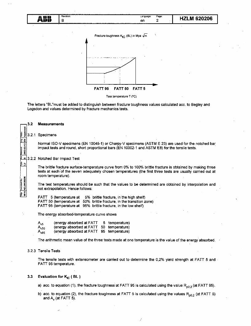
The development of KIC as a function of material temperature can be estimated by drawing a curvethrough the three points FATT 5 / 50 / 95; see figure.
We reserve all rights in this document and in the information contained therein. Reproduction, use or disclosure to third parties without express
I IR°eimn.: Lang uage: Page: HZLM620206Wall~ B en ua 2 H
Fracture toughness KIC (BL) in Mpa 4r
FATT 95 FATT 50 FATT 5
Test temperature T (OC)
The letters "BL'must be added to distinguish between fracture toughness values calculated acc. to Begley andLogsdon and values determined by fracture mechanics tests.
&
oQ4
o N
3.2 Measurements
3.2.1 Specimens
Normal ISO-V specimens (EN 10045-1) or Charpy-V specimens (ASTM E 23) are used for the notched barimpact tests and round, short proportional bars (EN 10002-1 and ASTM E8) for the tensile tests.
3.2.2 Notched Bar Impact Test
The brittle fracture surface-temperature curve from 0% to 100% brittle fracture is obtained by making threetests at each'of the seven adequately chosen temperatures (the first three tests are usually carried out atroom temperature).
The test temperatures should be such that the values to be determined are obtained by interpolation andnot extrapolation. Hence follows:
FATT 5 (temperature at 5% brittle fracture, in the high shelf)FATT 50 (temperature at 50% brittle fracture, in the transition zone)FATT 95 (temperature at 95% brittle fracture, in the low shelf)
The energy absorbed-temperature curve shows
Av5 (energy absorbed at FATT 5 temperature)Av50 (energy absorbed at FATT 50 temperature)Av95 (energy absorbed at FATT 95 temperature)
The arithmetic mean value of the three tests made at one temperature is the value of the energy absorbed.
3.2.3 Tensile Tests
The tensile tests with extensometer are carried out to determine the 0,2% yield strength at FATT 5 andFATT 95 temperature.
3.3 Evaluation for KIc ( BL)
a) acc. to equation (1), the fracture toughness at FATT 95 is calculated using the value Rp0 ,2 (at FATT 95).
b) acc. to equation (2), the fracture toughness at FATT 5 is calculated using the values Rp0,2 (at FATT 5)and Av (at FATT 5).

L IN1 Revision: Language: Pages HZLM 620206iiIP P B en 3 11
c) the fracture toughness at FATT 50 is determined as the mean values of a) and b).
d) in accordance with 3.1, the curve
KIC (BL) = f (T)
is obtained by drawing a curve through the three values.
4. Test Certificate
The certificate must specify the following particulars:
- Position of the tensile- and notched bar impact test specimens in the test piece or drawing number
- Results of the notched bar impact tests as
a) brittle fracture surface-temperature curve showing all 2,1 valuesE
b) energy absorbed-temperature curve showing all 21 measured values
- Energy absorbed Avs,, Av50, A195 ( J ) and temperatures FATT 5, FATT 50, FATT 95 (OC)9
- Result of the tensile tests at FATT 5 and FATT 95
-( Rp0 .2 ' Rm, Z, A5 )
- Fracture toughness-temperature curve including FATT 5 and FATT 95 with the calculated
values KIC (BL) at FATT 5 /50 /95 in Mpa N/.mE

ALSTOM ALSTOM Power ETL-EP-MAT 07-005O6paftemefnt responsable: D~partemnent destinatalro: R6vislon: Type doe: No flthlsr:
9010 BCrd: Vdrifid: Approud: Langue: Poge:
2007-05-16 MA MOREAUX 2007-05-16 J ROGE 2007-05-16 MC MAENNEL en 1 /11Domains d'application: Doc.d'origine: Romplace: No classification:
Inspection for internal defects - Ultrasonic examination
I Scope and time of examination
The ultrasonic examination shall take place at the following stages:
a) Before the quality heat treatment
b) After the quality heat treatment at a stage of the final machining, such that it should allow an-other quality heat treatment when the measured permeability is inadequate.
This inspection shall allow to specify which defects are acceptable before the quality heat treatmentand verify that such defects have not evolved in the course of the heat treatment.
The inspection shall be carried out in conformance with IBA R22405. The entire volume of the part
shall be examined with longitudinal waves.
The extent of the inspection for stage (a) is as follows:
For forgings, used for HP part of HIP rotors:- Specified in Attachment 6 to this document
For forgings, use for IP part of HIP rotors or for LP rotors:- Discs: item 1 of attachment 1 to this document- Shaft ends without integral disc: item 1 and 2 of attachment 2 to this document- Shaft ends with integral disc: item 1 and 2 of attachment 3 to this document- Rings: item 1 of attachment 4 to this document
For stage (b) the extent of inspection is as follows:
- For forgings, use for HP part of HIP rotors:- Only the inspection corresponding to item 1 in attachment 6 to this document shall be per-
formed. Any defective region (containing one or more indications exceeding the reportinglimits) detected during stage a) examinations shall undergo a further examination to checkthe evolution of indications.
- For forgings, use for IP part of HIP rotors or for LP rotors:- Discs: All of attachment 1 to this document- Shaft ends without integral disc: All of attachment 2 to this document- Shaft ends with integral disc: All of attachment 3 to this document- Rings: All of attachment 4 to this document'
Note: at stage (a) the supplier may supplement this inspection with order probing if he deems it neces-sary.
Ce document, propri6t6 exclusive de notre Soci&t6, est strictement confidentiel. II ne peut 6tre communiqu6, copid ou reproduit sans son auto-risation 6crite. © ALSTOM 2007

ALsTO) I RlRsion: Langue: Page:)ABLnT2/ 1 ETL-EP-MAT 07-005B en 2/11
2 Evaluation of indications
The indications shall be characterized in accordance with IBA R22405.
3 Reporting threshold and criteria
3.1 Reporting thresohold
The following shall be reported:
- Any area showing a reduction in the back echo amplitude exceeding 6 dB,
- Any indication of relecting capacity greater than or equal to the reporting threshold for themaximum severity class corresponding to the area in which the indication is located.
The acceptance classes are given in table N01.
For forgings used for HP part of HIP rotors, the diagrams showing maximum severity acceptanceclasses by area are given in attachment N07 to this document.For forgings used for IP part of HIP rotors or for LP rotors, the diagrams showing maximum severityacceptance classes by area are given in attachment N05 to this document.
Note: - For examination at stage:
a) corresponding to probing in axial direction of item 1 of attachment 3 to this document, theprobing sensitivity must enable detection of a defect with an equivalent diameter of 1,6 mmat a depth equal to the disc thickness.
b) corresponding to item 3 of attachment 2 to this document and items 1 and 3 of attachment 3to this document, the probing sensitivity must enable detection of a defect with an equivalentdiameter of 1,6 mm at a depth equal to the maximum radius of the part.
3.2 Criteria
The following shall be unacceptable:
- Any reduction in back echo amplitude exceeding 6 dB
- Any linear indication
- Any indication exceeding the acceptance criteria for the class of the area in which the indi-cation is located.
The acceptance classes are given in Table N01.
The diagrams showing the maximum severity acceptance classes are given in attachment N05 to thisdocument.
If one or more indications exceeding the acceptance criteria for the maximum severity class of the areaconsidered are detected, interpretation of the defect map shall be subjected to a detailed examinationby the forging shop, the manufacturer and the main contractor.
Ry son toLngue: P.g.:
ALST15M B en 3/11 ETL-EP-MAT 07-005
4 Reference documents
SBV MF 2004
SBV MF2005
IBA R22405
Particular technical specification of part - Low-alloy steel forgings for compo-nents of welded rotors for steam turbines
Particular technical specification of part - Low-alloy steel forgings for steam tur-
bine welded rotors service temperature below 300'C
Inspection methods - Ultrasonic examination of forgings

) RB en Page: ETL-EP-MAT 07-ou5ALSTOM B en 4/11 ET-P-A 07-00
TABLE N01
DEFINITION OF ACCEPTANCE CLASSES
Reporting Isolated Grouped ClusteredClass threshold indications indications indications
'max 0 (mm) max 0 (mm) max 0 (mm) max 0 (mm)
S 0,5 1 0,7 0,5
C 1 2 1,5 1
0 1,6 3 2 1,6
1 1,6 5 3 2

A LS (•y• s~ion• Langue: Page:AL )T M B en 5 / ETL-EP-MAT 07-005B en 5/11 11
ATTACHMENT 1
Ultrasonic inspection of discsForQinQs for LP rotors
Item Inspection - direction of probing Probing method
1- Straight beam
2 -Straight beam
h bladeattachment - Angle probes - Transversezone wave
(Angles between 450 and 700)
Weld
4 faces - S.E. probe
3 Ior

R4'S son Langu: Page:ALST M I en Pag ETL-EP-MAT 07-005B en 6/11 1
ATTACHMENT 2
Ultrasonic inspection of shaft endsForginqs for LP rotors
Item Inspection - direction of Poigmtoprobing
1 -Straight beam
- Angle probes - Transversewave
2- Refraction angles chosen tosuit geometry(in principle 450 and 600)
3 -Straight beam
4 3 -S.E. probe
Note : the examination corresponding to item N02 shall be carried out only in case of shaft ends wherethe balancing disc is obtained by upsetting.

ALSTR M Rsiion: Langue:. PageI:) Be 7/ ETL-EP-MAT 07-005
ATTACHMENT 3
Ultrasonic insDection of shaft ends with intearal discForainas-for LP rotors
Item Inspection - direction of. Poigmtdprobing Probing method
1 -Straight beam
-• - Angle probes - Transversewave
2 Refraction angles chosen tosuit geometry
(in principle 450 and 600)
3 -Straight beam
h blade - Angle probes - Transverseattachment wavezone (angles between 450 and 700)
5 3- S.E. probe
Note : the examination corresponding to item N°2 shall be carried out only in case of shaft ends wherethe balancing disc is obtained by upsetting.

ALSTROyM IR1ison: Langue: Page:) B en 8/11 ETL-EP-MAT 07-005
ATTACHMENT 4
Ultrasonic examination of rinasForqings for LP rotors
Item Inspection - direction of Probing methodprobing /
1- Straight beam
2 -Straight beam
0 t it 3 0 inm
Weld3 faces - SE. probe

L Ryioo: Lenguo: Page:ALSTO B en 9/11 ETL-EP-MAT 07-005
ATTACHMENT 5
Ultrasonic examinationLP rotor
LEGEND:
Classc C: Blade attachment area. Height is specified on inspectiondrawing cited in the purchase order.
(Weld faces): 30 mm deep area adjacent to the designatedfront face
IM . I Classe S:
•--'3 Classe 0
L7=. Classc I
* (1) Shaft end with integral disc* (2) Shaft end without integral disc

LSTORO Langue: Page: E 0
)M B en 10/11 ETL-EP-MAT07-005
ATTACHMENT 6
Forgings for HIP rotors
ExAminnhtonI ,•' Pro•bc orientat•.tm) Proh mij Ah I l.lhd
fl i-l l~~~U e 131 vai'ousO !h :im r '-wove. prob~esJ W hlf~tl.
du:•~~l,•Agnrilten. the. nnojlp. of divergen.nc the vnrtimm
-.... .. -a1. =. ° o •×l0
u nd alion r t.hsu ri.on)
2__•- J Add it .jonii
7E
Shuidow J-- probe ar e?,lotn Iionj or sth Iven nla I be
' " I77 ti .t0 mdeep in u I'7ra vim.in.uio , o" tho neckron
tJpr b i, o r ni u ut-ub~ p r ob e

RLST M so''n: Langeo: Page: .ALST )M B en 11/ i ETL-EP-MAT 07-005
ATTACHMENT 7
. HIP rotor
// /_zz~ lIL/LI /__K(EY
Class C. Region of blade attachment
1 OClans S (welding faces) r area 30 mm deep odjncent to the dergnntedfront face
Class 0
Class 11lP ROTOR 1500 rnd 1.000 rpm

UN#09-209
Enclosure 2
Affidavit Attesting to Proprietary Nature of theALSTOM Turbine Missile Analysis

AFFIDAVIT
COMMONWEALTH OF VIRGINIA )) ss.
CITY OF RICHMOND )
1. My name is Stephen Reinstein. I am the Legal Counsel for the Power Systems
Turbomachines Group of ALSTOM Power Inc. ("Alstom") and, as such, I am
authorized to execute this Affidavit.
2. I am familiar with the criteria applied by Alstom to determine whether certain
Alstom information is proprietary. I am familiar with the policies established by
Alstom to ensure the proper application of these criteria.
3. I am familiar with Alstom information contained in all the documentation
associated with the Alstom Turbine Missile Analysis Report and referred to
herein as "Documentation." Information contained in this Documentation has
been classified by Alstom as proprietary in accordance with the policies
established by Alstom for the control and protection of proprietary and
confidential information.
4. This Documentation contains information of a proprietary and confidential nature
and is the type customarily held in confidence by Alstom and not made available
to the public. Based on my experience, I am aware that other companies regard
information of the kind contained in this Documentation as proprietary and
confidential.
Page 1 of 4

5.. In order to satisfy the request of the U.S. Nuclear Regulatory Commission to be
able to make available and release for public viewing a portion of the
Documentation, Alstom has prepared a redacted version of the Documentation
which excludes the information which Alstom considers to be proprietary. This
redacted version is designated on each page as "Non-Proprietary Version".
Alstom is hereby releasing the redacted or non-proprietary version of the
Documentation to the U.S. Nuclear Regulatory Commission free of restrictions as
to its publication.
6. The full version of the Documentation has, however, been made available to the
U.S. Nuclear Regulatory Commission in confidence with the request that the
information contained in the full version of the Documentation be withheld from
public disclosure. The request for withholding of proprietary information is made
in accordance with 10 CFR 2.390. The information for which withholding from
disclosure is requested qualified under 10 CFR 2.390(a)(4) "Trade secrets and
commercial or financial information."
7. The followving criteria are customarily applied by Alstom to determine whether
information should be classified as proprietary:
(a) The information reveals details of Alsiom's research and development
plans and programs or their results.
(b) The availability or use of any such confidential design information to or
by a competitor of Alstom would provide such competitor with a
substantial improvement in the ability tomake competitive proposals that
reflect knowledge of Alstom design effectiveness that is not otherwise
Page 2 of 4

Available to the market. This competitive knowledge would allow such
competitor to propose equipment performance with a greater than
otherwise possible knowledge of Alstom's expected proposals, thereby
improving the competitor's probability of selection and contract award.
(c) The information includes test data or analytical techniques concerning a
process, methodology, component, or the detailed test results conducted
on turbine equipment supplied by Alstom, which would provide to a
knowledgeable reader, insights into the effectiveness of individual
elements of Alstom's designs, as well as in depth knowledge of the actual
performance of the complete equipment package, the application of which
results in a competitive advantage for Alstom.
(d) The information reveals certain distinguishing aspects of a process,
methodology, or component, the exclusive use of which provides a
competitive advantage for Alstom in product optimization or
marketability. The use by a competitor of such information would be to
the detriment of Alstom through the loss of contract awards, future sales
and future profits. All such information is of great value to Alstom in its
continuous design improvement process to meet the requirements of a
competitive marketplace.
(e) The information is vital to a competitive advantage held by Alstom, would
be helpful to competitors to Alstom, and would likely cause substantial
and irreparable harm to the competitive position of Alstom. The
information is of the type of information that Alstom zealously pursues
Page 3 of 4

and defends as confidential business information through the use of highly
restrictive confidentiality agreements that are not time limited in their
applicability.
The information in the full Version of the Documentation is considered
proprietary for the reasons set forth in paragraphs 6(b), 6(c), 6(d) and 6(e) above.
8. In accordance with Alstom's policies governing the protection and control of
information, proprietary information contained in the full version of the
Documentation has been made available, on a limited basis, to others outside of
Alstom only as required and under stringent agreements providing for
nondisclosure and limited use of the information.
9. The foregoing statements are true and correct to the best of my knowledge,
information, and belief.
Stephen Reinstein, Legal Counsel
Subscribed before me this 13th
day of April, 2009.
,,,. to.X T.W i .,
Andrea Woods *" ..Notary Public E;' L 4My Commission Expires December 31, 2009 :.'
Commission No. 365754• •'2"J
Page 4 of 4