Embed Size (px)
Citation preview
NO. REV. NO.
A' 718
b PAGE OF 14
Aerospace Systems Division
ALSEP FASTENER STUDIES DATE 6 December '67
This unscheduled ATM has been written to summarize and document all the design and testing effort conducted on the ALSEP fastener to date,
Prepared by: Warren Hamill
Approved by:
Approved by: T6ffis Fenske
Aerospace Systems Division
1. 0 Summary
ALSEP FASTENER STUDIES
2. 0 Fastener Requirements
2. 1 Original Fastener Requirements 2. 2 Modified Fastener Requirements
3. 0 Calfax Live Lock
3. 1 Fastener Research 3. 2 Evaluation Tests - Calfax Live- Lock
4. 0 Ca lfax Replacement Study
5. 0 Evaluation Tests - Calfax Replacements
5. 1 ALSEP Compartment# 1 Fastener Vibration Test 5. 2 Dynamic Load- Tensol Lock and Boydbolt Test 5. 3 Static Test - Tensol Lock Test
6. 0 Conclusions and Recommendations
7. 0 References
NO. REV. NO.
ATM718
PAGE 2 OF 14
DATE 6 December '6 7
NO. REV. NO.
ATM718
PAGE 3
OF 14
Aerospace Systems Division
ALSEP FASTENER STUDIES DATE 6 December •{,7
1. 0 SUMMARY
The Calfax Live Lock fastener was selected for the original design since it met all the requirements set forth for the ALSEP fastener.
After the astronaut review of the original hardware it was stated that the total time for deployment was excessive. Bendix was directed to design a fastener, or fastening system, which would reduce the time required for unfastening.
Bendix reviewed many fastening schemes and selected prom1s1ng candidates for further study and test. All fastening methods, other than the screw type, failed because the release force exceeded the capability of the astronaut while maintaining minimum structural integrity parameters.
The current recommendation is to use a Boydbolt, a 75° turn-torelease fastener, using a combination experiment handling and tie down release tool for unfastening. This recommendation meets the basic astronaut requirements, and satisfies all the structural specifications.
2. 0 FASTENER REQUIREMENTS
The fastener requirements were established twice; once for the original ALSEP fastener and once for the directed modified fastener. Sections 2. 1 and 2. 2 outline these specific requirements.
2. 1 Original Fastener Requirements
Bendix established the original fastener requirements from structural, human factors, and system engineering inputs. The original fastener criteria were as follows:
1) Physical properties high enough to satisfy the LM environmental loads; static and dynamic. {900 lbs. minimum tensile strength).
2) Capable of being quickly released with little effort, i.e., 17 inch-1bs on a 1 1/2" diameter handle.
NO. REV. NO.
A'~'M718
PAGE 4 OF 14
Aerospace Systems Division
ALSEP FASTENER STUDIES DATE 6 December 1 6 7
3) Quantity of fasteners minimized.
4) No "hang-up" after initial release or unfastening.
5) Cold welding eliminated.
6) Simple and convenient astronaut release tool interface.
7) Commonality throughout the ALSEP system.
8) No pyrotechnic devices are permitted.
9) Minimum weight.
10) Use materials which are non-magnetic.
From these requirements the Calfax Live Lock fastener was selected for the original A LSEP de sign (see Section 3. 0).
2. 2 Modified Fastener Requirements
After the crew had an opportunity to evaluate the Calfax Live Lock on a crew engineering mock-up, a number of objections were submitted. These objections resulted in a revised set of requirements with direction from MSC to replace the Calfax Live Lock fastener. The specific objectives were as follows:
1) Reduce the time and effort required to deploy A LSEP. The suggested method of approach was to reduce the quantity of fasteners and to develop a non-twist type fastener.
2) Positive indication that the release mechanism has been actuated.
3) The possibility of re-engagement or "hang-up" after unfastening must be eliminated.
4} The impact on the present ALSEP design will be held to a minimum. ( 1/4 inch limit for the fastener diameter).
NO. REV. NO.
ATM718
PAGE 5 OF 14
Aerospace Systems Dtvieion
ALSEP FASTENER STUDIES DATE 6 December 167
Section 4. 0 covers the study and testing conducted to satisfy these requirements.
3. 0 CALF AX LIVE LOCK
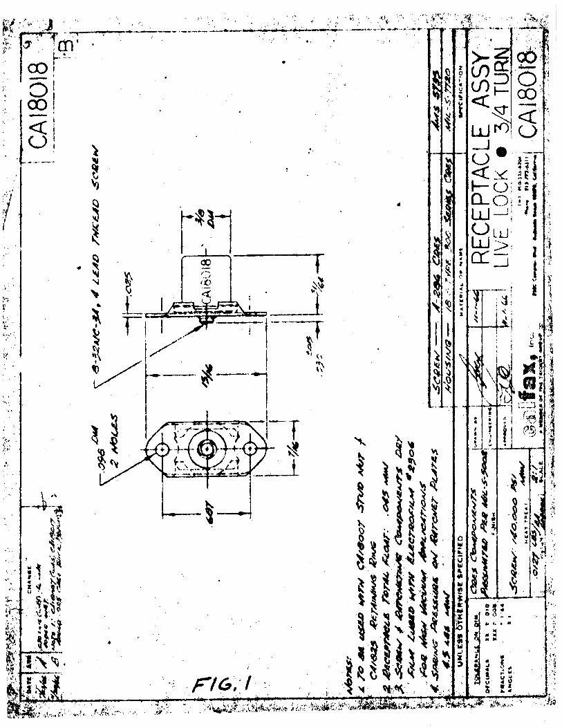
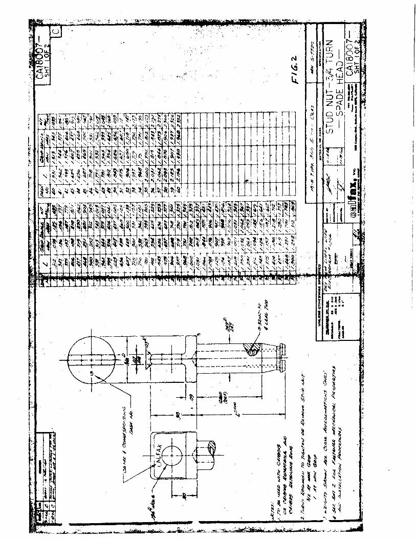
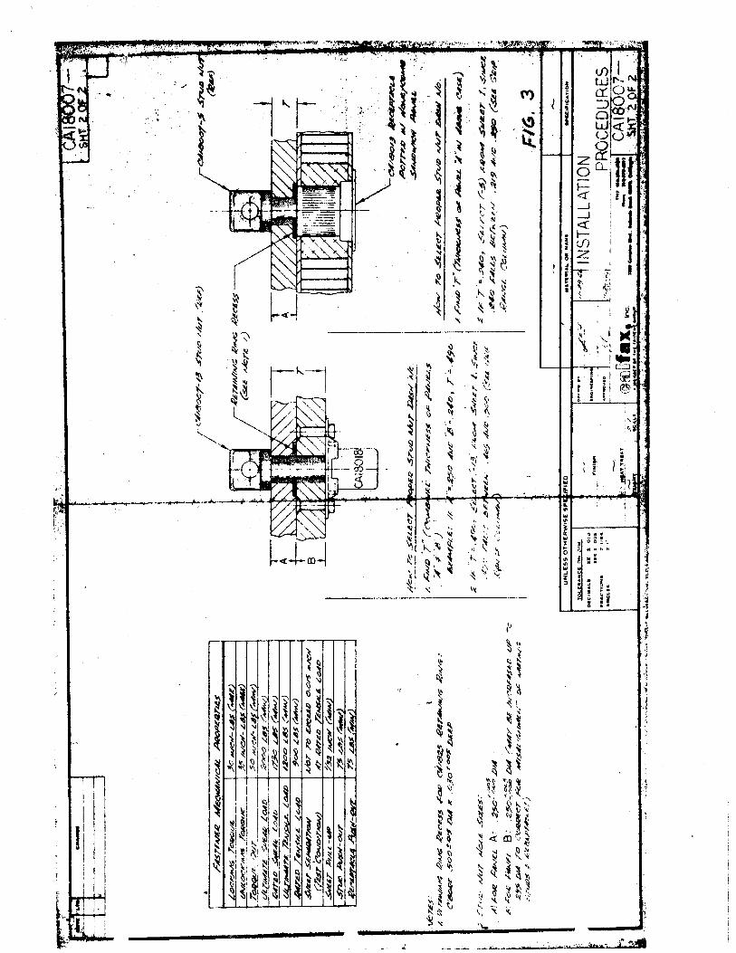
The Calfax Live Lock fastener (see Figures 1, 2, 3) was selected for the original design after extensive investigation. This investigation took the form of contacting specific fastener companies and agencies throughout the country.
The specific features of the Calfax Live Lock fastener which satisfy the requirements listed in Section 2. 1 are as follows:
1) Mechanical Properties for Calfax Live Lock, 1/4 diameter
Rated tension --- 900 lbs. Ultimate tension load --- 1200 lbs. Rated shear load--- 1730 lbs. Ultimate shear load --- 3000 lbs. Sheet separation --- not to exceed . 015 inch at rated
tensile load Locking torque--- 30 inch-lbs.
2) 3/4 to 1 turn to release fastener.
3) Incorporation of a retaining ring washer to prevent remote possibility of the stud tending to refasten .
4) Solid film lubricant (Electrofilm 2306) to prevent cold welding and provide a reliable lubrication system.
5) A total quantity of 19 fasteners were required to provide adequate tie down for the sunshield (this was proven minimum per test TR 2267, reference No. 13)
6) Dynamic integrity verified by Lockheed Missiles and Space Company's Test Report No. A5184-2, Litton Data Systems Test MJO 2907-12 and meets the requirements specified in MIL-F-22978A (references l, 2, 3, 4)
3. 1 Fasteners Research
Table 1 presents the fastener companies and the specific type fastener which were considered for the original ALSEP design.
Aerospace Systems Division
ALSEP FASTENER STUDIES
Table 1
Fastener Sources Researched
Company
Grumman Aircraft Bethpage, Long Island
Standard Pressed Steel Santa Ana, California
"A PIC" Apollo Parts Information Center, Huntsville, Ala.
Simmons Fasteners Albany, New York
Camloc Fastener Corp. Paramus, New Jersey
Cinch Monadnock City of Industry, Calif.
Deutsch Fastener Corp. Los Angeles, Calif. Dayton, Ohio
South Co. Fasteners
Dzus Fasteners West Islip, New York
Spi ron, Inc.
Timber-Top, Inc. Freeport, New York
Calfax, Inc. Torance, Calif.
Person Contacted
Robert Caughlin Jack LaRussa
J. Owens
Glen Lindsey Earl Pugh J. Rizzardi
William C. Kraft
J. Frederic Dreher
Applications Engineer
E. 0. Baumgarten
Dick Lowry
John M. Sadler
Frank Cosenza
NO. REV. NO.
ATM7l8
PAGE OF 14
DATE 6 December 167
Type of Fastener
General quick release and specificall v
Calfax' s Live Lock
Milson structural panel fastener
General quick release astronaut approved fasteners. Fastener test reports
Lock stud, Link lock
1/4 turn fasteners, Stressed panel fastener
Airlock (l/4 turn)
Oua rte r loc stud, Zip loc, Turn-loc, Press-loc fastener
Lion 1/4 turn
Universal Fastener, Standard 1/4 turn, Panel Fastener
High strength quick release
Mini- svnclamps quick release
Live lock, Boydbolt,
HO. REV. NO.
ATM718
PAGE 7 OF 14
A LSEP FASTENER STUDIES DATE 6 December '67
3. 2 Evaluation Tests - Calfax Live Lock
To prove the design integrity of the Calfax Live Lock fastener a number of tests were conducted by Bendix to expose any problems which might exist. The first three tests were pre Proto #1.
l) Calfax Fastener Vibration Test
Test Requirements- Memo 9712-190 (Reference No. 5) Test Report - TR 1980 (Reference No. 7) Date Conducted- 12/19/66
Summa rv - Th~ dummy Passive Seismic experiment (20 lbs.) was subjected to the existing qualification dynamic levels. The four Calfax Live 1 ock fasteners tested passed with no unfastening or unacceptable release torques.
2) Calfax Fastener Thermal Vacuum Test
Test Requirements - Memo 9712-190 (Refe renee No. 5) Test Report - TR 1942 (Reference No. 6) Date Conducted - 1/3/67
Summary - one mounted fastener was subjected to 1. 0 x 10-8 torr and 300°F for a period of 48 hours and 120 hours. No cold welding occured and all :release torques were under 18 in-lbs.
3) Calfax Fastener - Cold Environment
Test Requirements- Memo 9712-190 {Reference No. 5) Test Report - TR 2076 (Reference No. 8) Date Conducted- 2/1/67
Summary -One mounted fastener was subiected to low temperatures and its release torque recorded. Temperatures of -60°F can be experienct:•d by the fastener and still be released with less than 111 in-lbs. torque.
4) Proto # 1 Test
Test Requirements - Memo 9712-181 (Reference No. 9) Memo 9712-332 (Reference No. 10} Memo 9712-385 (Reference No. 11}
NO. REV. NO.
ATM718
PAGE 8 OF 14 Aerospace Systems Dlvltllon
ALSEP FASTENER STUDIES DATE 6 December 'f..7
Test Report- TR 2152 Date Conducted- 5/19/f..?
The first time the Calfax Live·Lock fastener was tested m the ALS'SP system was the Froto #1 structure for Compartment #l.
The test article consisted of the primary structure, thermal plate, sunshield, dummy experiments and dummy electronic modules. The Calfax Live-Lock fastener was used to retain all experiments and sunshield tie downs. The vibration environment was to the ATR-16 levels. These levels were more severe than the levels previously used (i.e., sinusoidal inputs at 50 cps required 6.0 g's for ATR-16 and previously required 3. 5 g's).
Loosening of the Calfax Live-Lock fastener occured on the experiments and sunshield during the sine sweep only. At no time did a fastener release completely, however, an improvement in the locking feature had to be made. A 11 efforts in connection with the unloosening problem on the Calfax Live-Lock were terminated when MSC directed Bendix to study and implement a non-twist type fastener to replace the Calfax Live-Lock.
4. 0 CALFAX REPLACEMENT STUDY
To satisfy the requirements set forth in Section 2. 2, an investigation into non-twist type fasteners was conducted. Table 2 presents the nontwist fasteners which were considered for the Calfax Live-Lock replacement.
In addition to the sources in the fastener industry, Bendix Aerospace investigated designs of various fastening methods listed in Table 3.
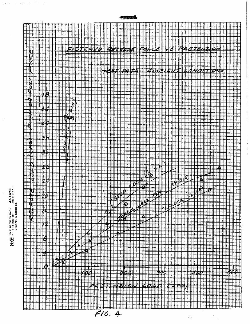
A common criteria of all the fastening systems was a 3 30 lbs. minimum pretension. This minimum requirement was established by testing on the Proto #1 model of Compartment #1 (see Section 5. 1). Along with this pretension requirement there are astronaut constraints which limit the release force capability as follows:
1) Maximum downward force - 20 lbs.
2) Maximum upward force - 5 lbs. (A LSEP lifts off lunar surface)
3) Maximum sideward force - 4 lbs. (assume .JA. = . 4)
NO. REV. NO.
ATM718
PAGE 9 OF 14
Aerospaoe Systems Dlvtelon
ALSEP FASTENER STUDIES DATE 6 December '67
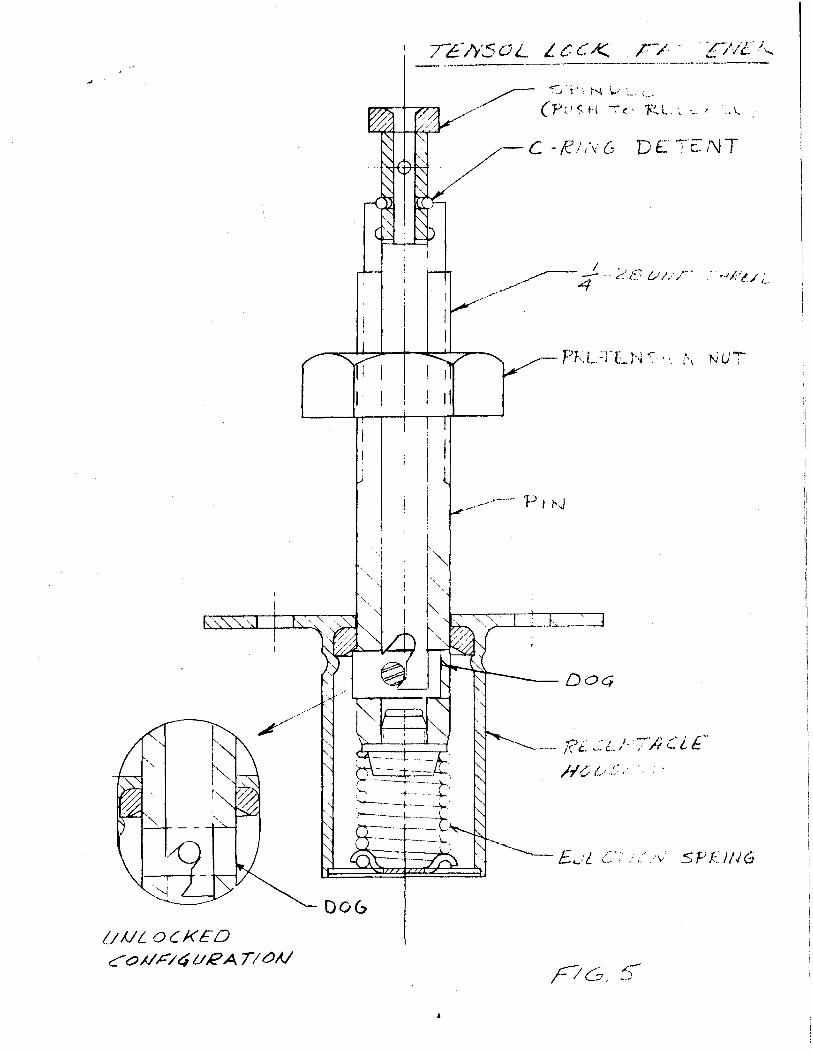
After preliminary investigation of the non-twist type fasteners·. both general industrv and Bendix designs, the Tensol Lock (push-torelease, see Figure 5) was selected as the basic design to develop and test further.
Figure 4 compares the pre load vs. release force required for each individual fastener evaluated in the study.
Although the Tensol Lock fasteners are not commonly made m the l/4" diameter size, preliminary tests run by Norco, Inc. (manufacturer of Tensol Lock) and their engineering iudgement indicated that the Tensol Lock would operate satisfactorily in the 1/4" size.
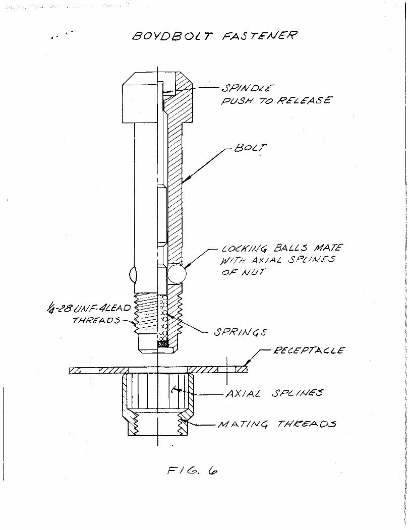
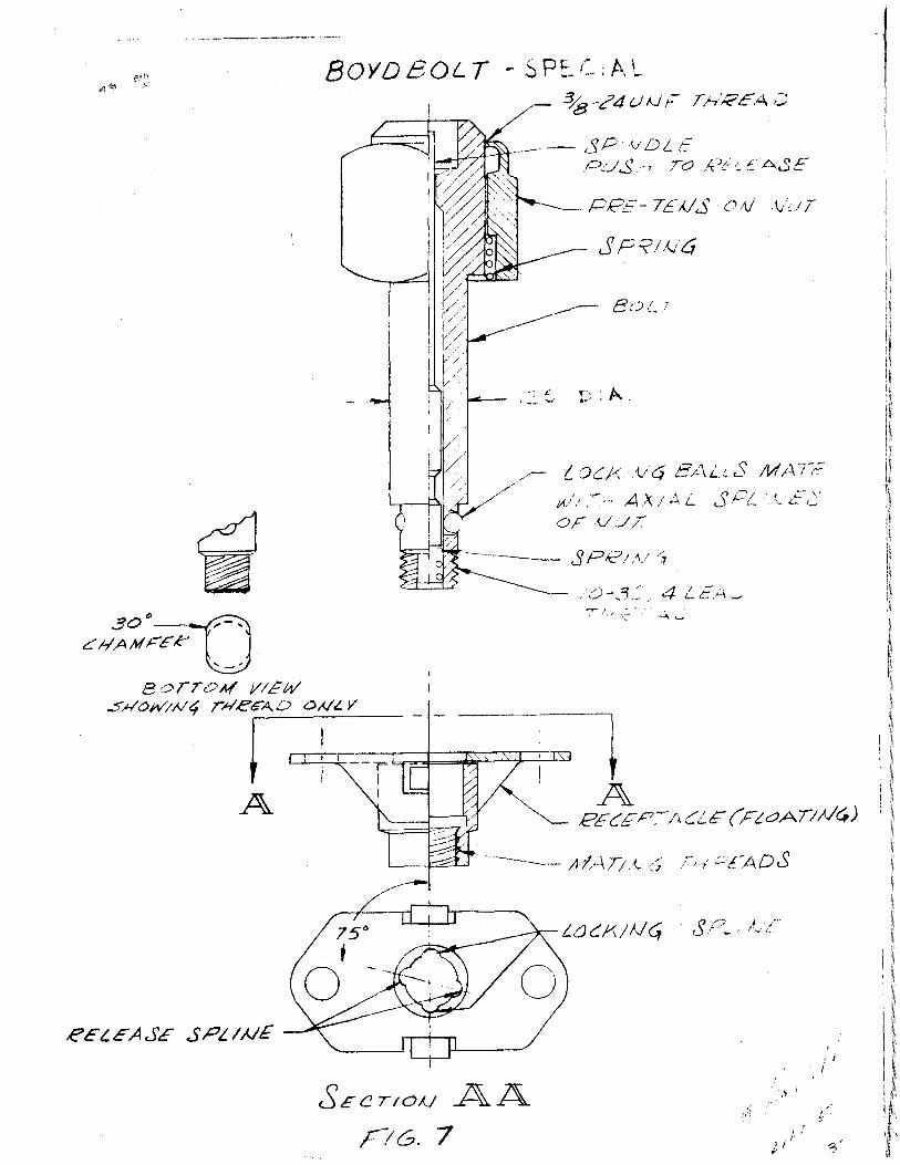
In addition to the non-twist type fastener a Boydbolt (twist type) was considered as a fastening back up method. The Boydbolt (see Figure 6) which basically is a fast lead screw with a pip pin locking feature looks very promising on paper in addition to the limited testing conducted on it. The basic or standard design has been modified to reflect certain features which satisfy the present ALSEP design criteria and is called a Boydbolt-special (see Figure 7).
The specific features of the Boydbolt-special are as follows:
1) 75° twist to release
2) Ball lock locking feature which provides a positive mechanical constraint against dynamic unloosening.
3) Locking spline in the unfastened position to prevent possible refastening.
4) A spring incorporated into the fastener head to assist fastener extraction and insure positive release.
5) Dead ending the threads such that a positive stop is provided when 75° has been turned.
6) A preloading nut to provide the necessary tension required and also allow slight variations in grip lengths.
NO. REV. HO.
A1:'M718
PAGE 10 OF 14 Aerospace System8 Division
ALSEP FASTENER STUDIES DATE 6 December 1h 7
7) Multisided socket head on the tie down release tool engagement interface.
8) Stepped down bolt shank to ensure that the balls in the locking mechanism do not protrude beyond the 1/4 inch shank.
The special version of the Boydbolt is in the development stage at this time, therefore evaluation testing on the specific flight design has not been done.
Table 2
Non Twist Type
Company Person Contacted Type of Fastener ================:::=::'.:=:j~=============-~-=-:i~~-=-=============== Avdel, Inc. Burbank, Calif.
Adjustable Bushing Corp. North Hollywood, Calif.
Space Lok, Inc. Burbank, Calif.
Norco Georgetowrt, Conn.
Duran
Ken Pitzer
R. Maddox
Heath McDowell Ray Metz
Table 3
Bendix Investigated Designs
1) Manual break-away bolts
2) Keyhole or elongated slide mechanisms
3) Pneumatic system
4) Ganged slide latch
5) Ganged push-pull mechanisms
h) Split nut on shouldered bolt
Ball-lok pins
Expando grip
Ouick release pip-pins, Test results in tension
'T'ensol lock, Stud lock, Cuplex}nterlock
HO. REV. HO.
ATM718
PAGE I 1 OF 14
ALSEP FASTENER STUDIES DATE 6 December '67
5.0 EVALUATION TESTS- CALFAX REPLACEMENTS
The objectives to be accomplished through testing were as follows:
1) Establish the minimum pretension and the minimum number of fasteners required to tie down the sunshield to the primarv structure.
2) "Evaluate the performance (dynamic and static} of the prototype Tensol-Lock fasteners, l/4" diameter, supplied by Norco, Inc.
3) Evaluate the dynamic performance of the Boydbolt fastener supplied by Tridair Industries.
Three separate tests were conducted to achieve these objectives, namely, the ALSEP Compartment # 1 Fastener Vibration Test, Dynamic Load-Tensol Lock and Boydbolt test, and Static Load-Tensol Lock test.
5. l ALSEP Compartment #1 Fastener Vibration Test
Test Requirements -Memo 9712-455 (Reference 13) Test Report- TR 2267 and Memo 9712-566 {Reference 14, 15) Date Conducted - 9/13/67
Summary- ALSEP Proto #1 model of Compartment #1 was subjected to a series of qualification level (LTA- 3) sine vibration tests.
The quantity (19 to 11) and preload {0 to 500 lbs.) of the sunshield fasteners were varied with each test and the resulting deflection and g load recorded.
A 330 lbs. pretension combined with the original quantity of sunshield fasteners (19) is the minimum recommended configuration. A 11 other combinations re suited in excessive sunshie ld deflections.
5. 2 Dynamic Load - Ten sol Lock and Boydbolt Test
Test Requirements- Memo 9712-521 (Reference 16) Date Conducted - 10/6/67
NO. REV. NO.
ATM718
PAGE l 3 OF 14
Aerospace Systems Divlelon
ALSEP FASTENER STUDIES DATE 6 December •()7
3) The Tensol Lock fastener tested did not show repeatibilitv in performance. Sometime the fasteners would work as desired, while at other times the release force would be extremely high. The main cause of its erratic performance is mainly due to the smallness in size (1/4" diameter). The 1/4" diameter Tensol Pin design is borderline and should not be considered further.
4) The Boydbolt successfully passed the LTA- 3 DR qualification levels on the LSM Proto #1 structure. The fastener satisfies the A LSEP design criteria and is adaptable into a 75 ° turn to release version.
This <J.esign is recom':nended as the basic fastening method for ALSEP.
5) As a future fastening m~thod the area of pyrotechnics should be reconsidered. These devices lend themselves to the ALSEP design because of the high quantity of fasteners needed.
7. 0 REFERENCES
Ref. No. bate
1 September •66
2. September '66
3 September '66
4 September •66
5 October '66
Identification No.
Report MJO 2907-12
Report A 5184-2
Report 1415138
MIL-F-22978A
Memo 9712-190
Title of Document
Litton Data Systems Calfax Panel Fasteners
Lockheed's Oualification Tests of "Calfax Type" High Strength Rotary Pane 1 F::t stene r s
General Specifications for Panel Fasteners, Rotary, Ouick Operating, High Strength
MIL SPEC. Fastener, Rotary, Ouick Ope rating, High Strength
Test Requirements - Calfax Fastener
Aerospace Syst..,. Dlvlalon
Ref. No.
6
7
8
9
10
11
12
13
14
15
16
17
ALSEP FASTENER STUDIES
Date Identification No.
January •67 TR 1942
February '67 Report TR 1980
April '67 Report TR 2076
October '66 Memo 9712-181
March '117 Memo 9712-332
May •67 Memo 9712-385
June '67 Report TR 2152
August '67 Memo 9712-455
October •67 Report TR 22h7
October '67 Report 9712-556
October '67 Memo 9712-521
October '67 Report TR 2260
NO. REV. NO.
ATM718
PAGE 14 OF 14
DATE h December '117
Title of Document
Test Report - Calfax Thermal Vacuum Evaluation
Test Report - Calfax Vibration Evaluation
Test Report - Calfax Cold Environment Evaluation
Test Requirements - Dynamic Test of ALSEP Compartment 1 Structural Assembly
TestRequirements - Dynamic Test of ALSEP Compartment 1 Structural Assembly
Test Requirements - ALSEP Proto #1 Compartment #1 Vibration Test
Test Report - ALS"EP Compartment #1, Proto No. 1
Test Requirement - A LSEP Compartment # 1, Fastener Vibration Test
Test Report - ALSEP Compartment # 1' (Prototype 1) Fasteners
Test Report - ALSEP Compartment #1 Fastener Vibration Test Results
Test Requirements - Calfax Fastener Replacement
Test Report - Static Load Calfax Fastener Replacements
--·-· ---~
'·. ~;:· · . ...... •., ...
· ..
', .··
R ~
N I V)
.{ ~ 1:: ..... l
'-" ..
• {
~ ~ \~ ~
~ ~ ~ r~ ~ ~
'\<~
~ 't'
~ ~ ~ ~ v
~ \'
-~ ~ "1~
~ "~ t l: ~~ ·.·· ~ ~
~ -~ l ~ ~
,, ~ ~ Zo_
~ ~ '( ll\ 01 ~~
l v_ . : ! 11.
~ ~' ~
~ f'v ,.
J j ' N ~~--.
~ .... } J v, ~ l .., . :) J 't
~ \) ~ ~ I
~ ~ ~ '-' ... I ~
l -~ .. ..... • 'I
,, . 1.!
~ ~ .~ ~ ~ ~ ~ ' l•:
\1 ~ ~· ~ ,~
"' :0
,•1 ...; ~ k.. .\. ~- \:_
~ ..
-~ ~ l'l ~ ~
·" .~
~ '~ ~
~ ' \\
' If\ ~ ' ·.•
.:: ..... . ·. ..... " -·;.· Mo.- -t .....
('I)
" ~ 10 ~ ci
u J: II:
u = Z VI - .. "' ~~ .. 0 u ;;l .... ~ ~ 0 0 :J -- .. >< )( "' o>: _,__
..f44 I
l !i tLj i 1 t1 i!tt' !, "11, T I,J ·" t 11! · ~ i!
1 •. l.r 1 tj'ri fl 1
1( :) '· .• :jl ll" !- "-
' f ' ' 1 11 ; , 1 . 11 1 , rl r r I , " ' . t. i . " J..HI:fR-t'' +1+1-I+H++H+J-+1!+ I++HH-t++H+++++++-I+++++H+J-t+t+tJ-1, H-++tl t+++t-tttr'l+t+t+H+J-ttf +t_ ttttt++f Ltt+~.+ i ~ ~~ i.! I ' I • " . ~ " 1 iH" 't "j +H+f
R- . r\ + i " ~" • l· l ! l "I I t
! ~ II
f' ~-"
J.
+ -
+
j rt J 1-
. ! y I .i
j i"
"~""
t
fH+H++++ 1 -
I l f i!rtJttt" tm.," tJ!:l
L
"it
I" I: "' ;
r-~ ~
f
I
""
I l
"I
t '"
HtHI~H-I+t+H+ •t ::t:t
" r
" J -I
UJJt..oCKED co#,.C/t;URATILJA./
Do&
r-· .. ,.. /' . ·· · r-, · , .. ' L I /c._/ ...... _, .,. ... --------·-----------------------------------
~ "':_,'\·',~'-1' .... ''-····-· ,. ( V • I <'; ' ' - · 1::> • / r 1.. • c \ . t~ ' r- ...... t. . ~ -_. , .. \ ..
C [:)•• .. !' - - ,c / i" (.:; D£ -~-·t:. NT
~ I.,,-~., .... - -- c:: .f. · / ·I··_. ~~ 4 .... (.;., ,.., .....
---·-···· ·pI,.. I _,.._... • ..- I''-J
.. I ~ /' ,.. L £" ......._____ 7? t.. , __ L I- ,· !""I l.. c:::
II .c ~~-· .:: · . ·
... .
~-?8 ON'F-4t..EAD ri-IREAD5
BOYDBOI.. T FASTENER
L-..J~+--SP/AI DLE PUSH 70 RELEASE
BOLT
!_OCK!J./4 BALLS MATE )1/l/-:;._. Ax/At.. SPL!NE5
OP' )../U T
SPR/N4S
PECEP/At::L€
~--AXIAL SPt:..I.AIE"S
FIG. (p
80YDBOLT -SP:_C;,A,\.
~ .30t:>-·~
C:: I-IAMI="E,e u B (~rroA{ 1/IEW
- ~--?4UA.ft::- Th:RC.~;J.. ;:;
---- 801._ 7
.. ,..:. ~' 1~~ : A. .
--/. •' ~·
-">H0h/IN4 THeeAD Ot</t. Y
~=-: ~·~·--l A A
l?E CFP.-r'/~ Cl..E" (FtoATINC,)
eEt.cASE SPLINE
SECTIOIJ AA F?G. 7
' I ;\ '
' ! i
. ' !