Embed Size (px)
Citation preview

www.iFlyUltraCam.com
www.iFlyUltraCam.com
OrthoGeneration
EssentialsDense
Matching
AerialTriangulation
Radiometry
www.iFlyUltraCam.com
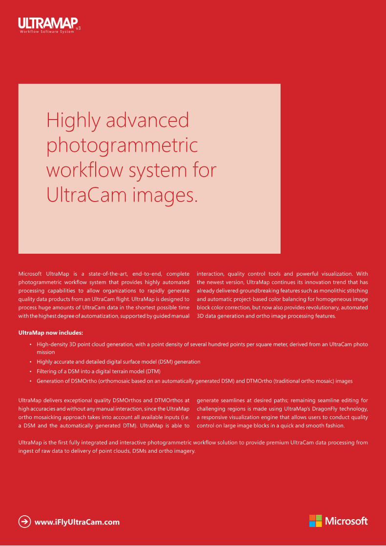
Microsoft UltraMap is a state-of-the-art, end-to-end, complete photogrammetric workflow system that provides highly automated processing capabilities to allow organizations to rapidly generate quality data products from an UltraCam flight. UltraMap is designed to process huge amounts of UltraCam data in the shortest possible time with the highest degree of automatization, supported by guided manual
interaction, quality control tools and powerful visualization. With the newest version, UltraMap continues its innovation trend that has already delivered groundbreaking features such as monolithic stitching and automatic project-based color balancing for homogeneous image block color correction, but now also provides revolutionary, automated 3D data generation and ortho image processing features.
UltraMap now includes:
• High-density 3D point cloud generation, with a point density of several hundred points per square meter, derived from an UltraCam photo mission
• Highly accurate and detailed digital surface model (DSM) generation
• Filtering of a DSM into a digital terrain model (DTM)
• Generation of DSMOrtho (orthomosaic based on an automatically generated DSM) and DTMOrtho (traditional ortho mosaic) images
UltraMap delivers exceptional quality DSMOrthos and DTMOrthos at high accuracies and without any manual interaction, since the UltraMap ortho mosaicking approach takes into account all available inputs (i.e. a DSM and the automatically generated DTM). UltraMap is able to
generate seamlines at desired paths; remaining seamline editing for challenging regions is made using UltraMap’s DragonFly technology, a responsive visualization engine that allows users to conduct quality control on large image blocks in a quick and smooth fashion.
UltraMap is the first fully integrated and interactive photogrammetric workflow solution to provide premium UltraCam data processing from ingest of raw data to delivery of point clouds, DSMs and ortho imagery.
Highly advanced photogrammetric workflow system for UltraCam images.

UltraMap/Essentials | The UltraMap/Essentials module is responsible for converting the raw images taken by the UltraCam into standard file formats that can be used by further processing steps in UltraMap and/or third party software systems. The UltraMap/Essentials module is divided into two processing steps:
UltraMap/RawDataCenter | The UltraMap/RawDataCenter step is responsible for processing the UltraCam imagery from level-0 to level-2. By exploiting the distributed UltraMap Framework, processing tasks can be handled in parallel.
UltraMap/Radiometry | The UltraMap/Radiometry step is responsible for defining the final color of the level-2 data. It also provides model-based radiometric correction to compensate for or remove hotspots, atmospheric effects and haze, exploiting Dragonfly technology for image interaction and visualization of large image blocks.
UltraMap/AT | The Aerial Triangulation (AT) module provides an interactive workflow while calculating image correspondences in order to generate a precise exterior orientation for an entire image block by means of a least-squares bundle adjustment.
UltraMap/DenseMatcher | The UltraMap/DenseMatcher module creates high-density point clouds, DSMs and DTMs from level-2 images by extrapolating precise exterior orientation data to generate per-pixel height values. The 3D point cloud and the DSM data can be exported in standard file formats for further 3rd party processing.
UltraMap/OrthoPipeline | The UltraMap/OrthoPipeline module generates the final ortho mosaic from all available inputs such as level-2 imagery, AT results, radiometric settings, and the DSM/DTM. Two different ortho images can be generated: DSMOrthos and DTMOrthos.
Modules
AT
DenseMatcher
OrthoPipeline
Essentials

Essentials
Download, management and postprocessing of the raw image data.
UltraMap/Essentials
• Application of camera calibration • Usage of flight metadata• Automated UltraMap project file setup• Radiometric adjustments

www.iFlyUltraCam.com
UltraMap/RawDataCenter
The UltraMap/RawDataCenter step of the UltraMap/Essentials module is responsible for downloading and processing of UltraCam images from level-0 to level-2, including:
• Geometrical corrections • Monolithic stitching
• Radiometric corrections• Generation of the UltraMap project file
Geometrical corrections
UltraCam images are captured during aerial acquisition and stored in the raw format. Each shot position contains a number of sub-images. Each sub image corresponds to one single CCD sensor array and needs to be processed and converted by means of image stitching. The software identifies tie points in the overlapping regions and uses these for composing the virtual image frame. The quality of this correlation process is at a 1/20 of a pixel magnitude. Furthermore the Laboratory Calibration plays a significant role in this process and allows estimation of tie point positions to avoid mismatch and larger search areas. Metadata information, such as temperature readings, is included in order to
describe the conditions of the camera at the moment of image capture. The result of this process is the so-called level-2 image. It contains the high-resolution panchromatic image at the 16-bit per pixel data range and the 4-band multispectral image at 16-bit per band data format. It is worth noting that radiometric corrections are also applied to level-2 images based on the laboratory calibration (cf. radiometric corrections). As level-2 images are stored at 16-bit per band the radiometric domain is a linear domain without any logarithmic modification. Thus, one may call the level-2 image the “Digital transparency”.
Monolithic stitching
The monolithic stitching generates one full frame PAN image out of the nine PAN sub-images taken by the camera. It combines information from the PAN sub-images as well as information from the full frame color cones to collect tie points for the stitching. This leads to strong tie points between the sub-images even under critical conditions, such as images containing water bodies or images with unstructured terrain, such as sand desert. As a result, the full PAN frame has a very robust and
high accuracy literally as if it were collected by one large CCD through one lens. However the use of multiple smaller CCDs has significant benefits such as much higher image dynamic compared to single large CCDs. So, the monolithic stitching of UltraMap enables combining the benefits of image quality of smaller CCDs with the accuracy of large CCDs by avoiding the disadvantages of the latter.
Stitching between panchromatic image areas allow collection of a large number of points at distinguished areas (left) and full frame distribution based on the color channel (right).
Stitching results are well documented by UltraMap. Thus one may study details of the level-2 processing and the stitching (left) or enjoy the comprehensive overview with color-coded image frames (right).

Essentials
Radiometric corrections
The radiometric correction is based on the radiometric parameters of the camera which are estimated during the Laboratory Calibration procedure. The parameters contain all information about the lenses, mechanical shutters and CCD detector arrays.
Thus, the radiometric behavior of the camera is already known at a distinct quality level and can be adopted during the processing from raw images (level-0) to level-2. For this data, different F-stop settings are considered and the resulting vignetting masks are made available to the process.
In a second step, the results from the radiometric analysis of CCD overlap areas is used to fine-tune the radiometric correction and remove any visible difference from adjacent image areas. Again the full frame color band contributes to this procedure and thus the monolithic stitching procedure also has an important benefit to the radiometric correction.
A Vignetting Mask (left) and a shutter control diagram (right) are shown below as results from the radiometric laboratory calibration procedure.
Vignetting Mask (left) and a shutter control diagram (right) are shown as results from the radiometric laboratory calibration procedure.
Structure of the post process level-2 data. Project file, full resolution images and quick videos are available.
UltraMap Project File
This file is generated fully automatically during the first step of the processing. The file contains all important data and metadata of the distinct aerial project such as image file names, directory structure, camera parameters and initial exterior orientation data, as well as results from the ongoing processing. The UltraMap Project File has the
extension .dfp and contains the basic information to allow any further automated processing of the entire photo mission. Below the Project File (e.g. UCEf80.dfp) can be recognized directly within the selected project folder listing.

www.iFlyUltraCam.com
UltraMap/Radiometry
The Radiometry step of the UltraMap/Essentials module is responsible for defining the final color of the level-2 input data and to generate level-3 output data. The step is fully automated and provides
a rich feature set to adjust the color appearance of single images as well as the appearance of a whole block. However, deep manual interaction is possible to fine-tune the results to specific needs.
Examples of the feature set are:
• Automated, model-based radiometric correction to compensate for or remove hotspots and/or atmospheric effects such as haze
• Project based color balancing (PBCB) for automated color correction of whole blocks. Effects such as different exposures, different illumination conditions and different flying time are corrected automatically
• Smooth visualization and interaction of small and large blocks by the Dragonfly technology
• Easy and intuitive user interface based on modern GUI technology and instant feedback
• Full support of 16-bit workflow guarantees lossless computation of images
• Various output formats for level-3 such as TIFF, 16bit TIFF, JPEG, single band, 3 band or 4 band
www.iFlyUltraCam.com
The UltraMap/Essentials module is supported by the Dragonfly technology for the visualization and by the framework for distributed processing. This enables UltraMap to scale depending on throughput needs and IT infrastructure. Features such as distributed parallel processing (multi-core processing) with automated load balancing optimize throughput in heterogeneous networks without requiring any user interaction. The framework enables parallel processing on single computers as well as on small, medium and large multi-core systems.

AT
• Automated tie point collection • Semi-automatic ground control point measurement• Full integration of post-processed GPS/IMU data• Photogrammetric bundle adjustment• Various export formats
Generation of high quality image exterior orientations based on camera data, ground control and airborne GPS/IMU.
UltraMap/AT

www.iFlyUltraCam.com
UltraMap/AT
UltraMap/AT is the aerial triangulation module of UltraMap, optimized for UltraCam to deliver utmost quality. It provides an interactive workflow while calculating image correspondences to generate a precise exterior orientation for an entire image block. UltraMap/AT also focuses on a high degree of intelligent automatization. Wherever interaction is
required, UltraMap/AT is designed to keep this interaction at a minimum, make it efficient and provides significant guidance for the interaction, such as the manual guided tie point improvement in the rare case that the automated tie point collection did not provide the best possible results.
Features of UltraMap/AT are:
• Uses in-flight GPS information for initial orientation• Single and multi-projection for ground control points• Initialization of project-based color balancing• Robust and automated tie point collection:
• Auto-completion for manual point measurement• High accuracy due to a combination of feature-based and least-squares image matching• Sophisticated image-based tie point thinning for optimal coverage• Guided manual point measurement (control points and tie points)
• Integrated photogrammetric bundle adjustment• Support for GPS/IMU data as a constraint for the bundle adjustment• Graphical overlays for AT results• Blunder detection, data snooping
• Full support for all UltraCam cameras• Full support of 16-bit workflow• Supports scalable processing environments• Smooth visualization and interaction of small and large blocks by the Dragonfly technology
Tie point distribution in the AT block, color coded visualization.
Visualization of ground control points, graphical output of measurement precision.

DenseMatcher
A significant change in photogrammetry has been achieved by Multi-Ray Photogrammetry which became possible with the advent of the digital camera and a fully digital workflow. This allows for significantly increased forward overlap as well as the ability to collect more images but virtually without increasing acquisition costs. However, Multi-Ray Photogrammetry as a first step is not a new technology; it is a specific flight pattern with a very high forward overlap (80%, even 90%) and an increased sidelap (up to 60%). The result is a highly redundant dataset that allows automated “dense matching” to generate high resolution, highly accurate point clouds and digital surface models.
Automated generation of height fields.
UltraMap/DenseMatcher

www.iFlyUltraCam.com
UltraMap/DenseMatcher
The UltraMap/DenseMatcher automatically generates point clouds from a set of overlapping UltraCam images. This is done by “pixel based matching” between all image pairs available for a given location on the ground. The precise exterior orientation is extrapolated and generates a height value (z-value) for a given pixel (for a given x, y, location). The redundancy of the image data set leads to multiple observations of z-values for a given location which will then be fused into one precise 3D measurement using sophisticated fusion algorithms. The remarkably high point density of the point cloud is typically of several hundred points per square meter.
The achievable height accuracy of the point cloud is usually better than the GSD of the underlying images, thus a 10cm imagery leads to <10cm height accuracy of the resulting point cloud. This detailed and precise point cloud is used to generate a digital surface model (DSM). Thanks to the high point density, this DSM has remarkably sharp edges and a very high level of detail.
The next step after the DSM generation is the processing of a DTM. The DTM is processed out of the DSM using a hierarchical algorithm developed by Microsoft.
Outputs of the UltraMap/DenseMatcher are:
• considerably dense point clouds
• Digital surface model (DSM)
All outputs are available in standard formats for easy ingest into third party software systems. The digital terrain model (DTM) is currently only being used internally in the UltraMap/OrthoPipeline for DTMOrtho image processing.

OrthoPipeline
• Rectifying images based on the available height fields either the Digital Surface Model (DSM) or the Digital Terrain Model (DTM)
• Quality control tools and interaction possibilities for the automatically generated seamlines
• Compositing full resolution mosaics for the output products DSMOrtho and DTMOrtho
Microsoft UltraMap introduces a fully automated processing pipeline for DSMOrtho and DTMOrtho generation.
UltraMap/OrthoPipeline

www.iFlyUltraCam.com
The DTMOrtho is the traditional ortho image, processed by rectifying the images with a DTM that has also been generated automatically by the UltraMap/DenseMatcher. The seam lines have been generated automatically using information from the image content as well as from the height field. Manual editing tools support seamline optimization.
UltraMap/OrthoPipeline
The DSMOrtho image is an ortho image which has been generated by rectifying the image, using the automatically generated DSM. This leads to a special ortho image with no perspective view and no leaning objects, which has significant benefits in some applications. Due to the consistent workflow, the DSMOrthos generated by UltraCam and UltraMap are of remarkably high-quality with very sharp
edges, very detailed structures such as roof structures, and very little artifacts. That is because the dataset (DSM and images) comes from the same flight and no time difference has caused any changes on ground which could result in artifacts. Another reason for the high quality is the extremely sharp and precise DSM that has been processed from the point cloud, thanks to the high point density of the point cloud.
The UltraMap/OrthoPipeline consists of several steps which are performed in a sequence:
Ortho rectification: the first step in the UltraMap/OrthoPipeline is called ortho rectification which re-projects the input images on a defined proxy geometry such as the DSM or the DTM. Depending on the type of the geometry used for the rectification, the result will be either a DSMOrtho or a DTMOrtho image.
Seamline generation: after the ortho rectification process, the next step is the seamline computation between the rectified images. Seams correspond to transitions from an input image to the adjacent one.
Ortho compositing: Once the initial ortho process is done, the software offers automated functionality to blend image content together in order to create a visually appealing result. All image bands (RGB and Near Infrared) are processed simultaneously in a consistent way.
RGB-DSMOrtho CIR-DSMOrtho
RGB-DTMOrtho CIR-DTMOrtho

Processing Environment
The UltraMap processing pipeline is a highly scalable processing system that adapts flexibly to the IT environment.
Key features are:
• Use of mid-to-high-end standard Windows PCs is possible, allowing the use of existing infrastructure.
• Distributed processing in heterogeneous networks with automated load balancing ensure optimal usage of resources.
• User controlled priorization allows to use dedicated machines at dedicated time slots (e.g. using a workstation for UltraMap processing during night time).
• Licensing scheme allows a wide spectrum of throughput needs. UltraMap can literally be executed on a laptop as well as on a processing system consisting of tens, or dozens or even hundreds of CPU cores and, as an option, additional GPU cores.
• Licensing scheme supports parallel setup of small field processing hubs (e.g. for immediate on-site quality checks after a flight) as well as setup of small, medium and large processing centers.
• GPU nodes deliver high-speed ups as the dense matching is ideal for a SIMD architecture such as graphics cards. Usage of CPU versus GPU can be configured to balance throughput.
• New role definitions in the UltraMap system provide high performance - an entire machine can be used to work on one task at a time (resource intensive machine). These machines can either be configured as CPU only or as GPU-enabled nodes.

www.iFlyUltraCam.com
An UltraMap processing system usually consists of one or several front-end machines that are used to interact with the data and are not designed for processing. In addition, one or multiple processing machines are connected to the front end machine(s) and the data server(s). The processing machines handle data processing and may consist of multiple CPU and/or GPU nodes. The servers host the input, intermediate and final data. A very important part of the processing environment is the network required to transfer the data efficiently between front end, processing machines and servers. All of the network traffic and workload distribution is handled by the coordinator machine.
WorkPlaces
CentralCoordinator Workers

Contact Us
Microsoft UltraCam Group | Vexcel Imaging GmbH | Anzengrubergasse 8, 8010 Graz, AUSTRIAwww.iFlyUltraCam.com | [email protected]
© 2014 Microsoft Corporation. All rights reserved. Microsoft, UltraMap, UltraCam, UltraNav and UltraMountare either registered trademarks or trademarks of Microsoft Corporation in the United States and/or other countries.
UM-E-OV-0414-1.0-A4
![O No Stitching [Single laver suit only] Stitching Styles Stitching ...hotshoeracewear.com/wp-content/uploads/2018/12/Suit-Order-form-… · [Single laver suit only] Stitching Styles](https://img.pdfslide.us/doc/110x75/5ed667d875f83015187a9121/o-no-stitching-single-laver-suit-only-stitching-styles-stitching-single-laver.jpg)