Embed Size (px)
Citation preview

© ALCOR SYSTEM 1
ALPHEA “All Sky” Camera
Installation and user manual
March 3rd, 2020 revision

© ALCOR SYSTEM 2
Table of Contents
1 Camera installation ................................................................................................................................................... 3
1.1 Camera installation ........................................................................................................................................... 3
1.2 Connecting camera ........................................................................................................................................... 4
1.3 Camera optical settings ..................................................................................................................................... 7
2 Software .................................................................................................................................................................... 8
2.1 System requirement and operating system ...................................................................................................... 8
2.2 Camera installation software ............................................................................................................................ 8
3 Using the camera software control ........................................................................................................................ 11
3.1 Initializing ........................................................................................................................................................ 12
3.2 Storage of files produced by the camera control software ............................................................................ 17
3.3 Camera exposure time and gain ..................................................................................................................... 19
3.3.1 Manual mode .......................................................................................................................................... 19
3.3.2 Automatic mode ..................................................................................................................................... 19
3.4 Image hot pixel removal using dark frame image........................................................................................... 20
3.4.1 Achieving master dark frame .................................................................................................................. 24
3.4.2 Residual hot pixels repair/fix .................................................................................................................. 26
3.5 Setting the overlay grid ................................................................................................................................... 28
3.6 Cyanogen Boldwood or Sentinel cloud sensors link with camera control software ...................................... 31
3.7 Magnitude per square second display image mode ....................................................................................... 32
3.8 Telescope control software link ...................................................................................................................... 34
3.9 Star count for cloud coverage estimation ....................................................................................................... 34
3.10 24h overview ................................................................................................................................................... 35
4 Sphere condensation and heating management .................................................................................................... 38
4.1 Introduction .................................................................................................................................................... 38
4.2 Adjusting and start-up .................................................................................................................................... 38
5 Camera maintenance .............................................................................................................................................. 39
6.1 Sphere cleaning ............................................................................................................................................... 39
6.2 Camera internal desiccant replacement ......................................................................................................... 39
6 Trouble shooting ..................................................................................................................................................... 39
6.1 Camera does not deliver images ..................................................................................................................... 40
6.2 Dew inside the dome ...................................................................................................................................... 40
6.3 Focus Drift ....................................................................................................................................................... 40
7 Product terms of use ............................................................................................................................................... 41

© ALCOR SYSTEM 3
1 Camera installation
1.1 Camera installation
The camera works outdoor, it is weather-tight. Warning, the system is not submersible: it is not a diving
camera. Moreover, it will prevent all intrusion of insects, even the smallest one.
The camera has no mechanical shutter and Sun’s heat does not cause loss of operation of the camera.
Please do not install the camera near a pollution source (like a chimney). Give as much exposure as possible
and avoid obstacles.
It is advised to level the camera with respect to the ground.
This version of camera has manual enabled heater that can remove external condensation that can occur on
sphere surface and two sealed connectors.
The camera has three anchors on the back, these three ISO M6 not thru threaded holes by 10 mm depth.
Use the supplied screws to fix or equivalent stainless steel A4 or A2 screw. The following stand can be used
to install the camera safely (this is an optional item, purchased on request)
Fig. 1 Optional stand for the camera

© ALCOR SYSTEM 4
Fig. 2 The position of the three M6 screws underneath the camera and the two connectors
The N, S, E and W direction is defined by rotating the camera accordingly. This is up to the user to define
camera orientation according to its needs. Please perform image capture tests before attaching the camera
to the pole.
1.2 Connecting camera
There are two cables providing, power supply (24V) and USB connection to the host PC.
The current provided by the power supply unit (PSU) is enough to power the camera and the dome heater.
Three kind of main’s AC plugs are provided on request: EU, US and UK type.
The user must look at the connector pins at the end of the cord, and their orientation to connect the camera,
in order to avoid forcing the pins and damage the camera connector.

© ALCOR SYSTEM 5
Fig. 3 USB and power cable connected to the camera.
The camera comes with unplugged cables. It can be attached by pushing the connector and rotating the top
ring. Please pay attention not to mix the 2 pins and 6 cables, this could destroy the camera. Also, the
connector has a key index (notch) that orientates properly the connector. Before pushing it, please align the
connector key index to the one located at the cable’s connector.

© ALCOR SYSTEM 6
Fig. 4 Left, camera panel connector, right cable connector, please align key to the notch prior attaching the connector
to the camera.
Fig. 5 Steps to detach (left) and attach (right) the cable connector to the camera
© ALCOR SYSTEM 7
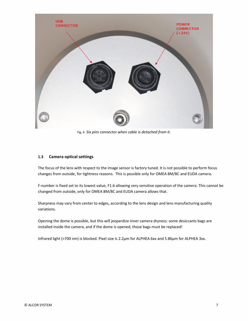
Fig. 6 Six pins connector when cable is detached from it.
1.3 Camera optical settings
The focus of the lens with respect to the image sensor is factory tuned. It is not possible to perform focus
changes from outside, for tightness reasons. This is possible only for OMEA 8M/8C and EUDA camera.
F-number is fixed set to its lowest value, F1.6 allowing very sensitive operation of the camera. This cannot be
changed from outside, only for OMEA 8M/8C and EUDA camera allows that.
Sharpness may vary from center to edges, according to the lens design and lens manufacturing quality
variations.
Opening the dome is possible, but this will jeopardize inner camera dryness: some desiccants bags are
installed inside the camera, and if the dome is opened, those bags must be replaced!
Infrared light (>700 nm) is blocked. Pixel size is 2.2µm for ALPHEA 6xx and 5.86µm for ALPHEA 3xx.
© ALCOR SYSTEM 8
2 Software
Latest camera software can be found in our web site:
http://www.alcor-system.com/us/AllSkyCamera/softwares.html
2.1 System requirement and operating system
Hardware requirement (Minimum)
• PC with AMD or Intel CPU, can work with low end CPU such as
o Intel Celeron M 440 @ 1.8GHz
o Intel Atom CPU D525 1.8Ghz
See ranked CPU performance here:
http://www.cpubenchmark.net/low_end_cpus.html
• 2 GB Memory
• 50 GB hard disk. Software requires 20 MB for installation, but storage must be granted for images.
Operating system requirement
• Windows 10, 8, and 7. 32 or 64 bits OS.
May work with windows XP, but no support will be provided for this OS.
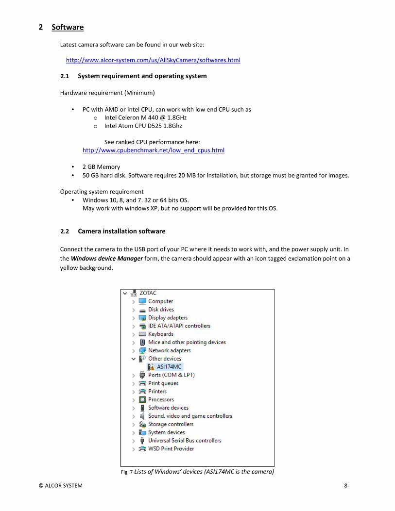
2.2 Camera installation software
Connect the camera to the USB port of your PC where it needs to work with, and the power supply unit. In
the Windows device Manager form, the camera should appear with an icon tagged exclamation point on a
yellow background.
Fig. 7 Lists of Windows’ devices (ASI174MC is the camera)

© ALCOR SYSTEM 9
Run setup_skywatch.exe, it will install all the software required for this camera. Be sure that this is
“Skywatch OMEA/ALPHEA Setup” and not any other setup software (another setup software for EUDA
camera is available). The next screen copy shows you how installation runs
Fig. 8
Fig. 9
Fig. 10
Then comes the camera driver installation software:

© ALCOR SYSTEM 10
Fig. 11 ALPHEA Camera device driver installation process.
Fig. 12 XVID video compressor installation.
Once the drivers are installed, the camera appears in the device manager either as ZWO ASI174MC, ZWO
ASI174MM, ZWO ASI178MC or ZWO ASI178MM, depending on the model of the camera.

© ALCOR SYSTEM 11
Fig. 13 Camera properly installed in the device manager.
The main’s software icon appears on the desktop.
Fig. 14 Icon of the camera software, double click to start it up.
- Software installation is now completed -
3 Using the camera software control
This software is fairly intuitive; the documentation will focus on features that are more difficult to acquire.
Access to the menu bar is located in the upper left, and a flying window in the foreground can quickly adjust
the software settings.

© ALCOR SYSTEM 12
3.1 Initializing
On first software startup, the software display a log window, which disappear by itself within 20sec and
heating control window. Click “Close forever” to close it.
Fig. 15 Heating window software, close it, it will not be used by this camera.
The software is set to simulation camera, and must be changed to the proper camera. Click
“Options/Camera Setup…”
Fig. 16
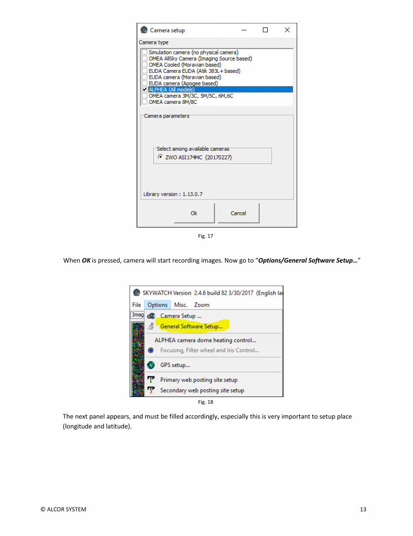
Select "ALPHEA (All models)", the connected camera must appear below:
© ALCOR SYSTEM 13
Fig. 17
When OK is pressed, camera will start recording images. Now go to “Options/General Software Setup…”
Fig. 18
The next panel appears, and must be filled accordingly, especially this is very important to setup place
(longitude and latitude).

© ALCOR SYSTEM 14
Fig. 19

© ALCOR SYSTEM 15
Fig. 20
Once the camera is selected, the exposures start immediately. Then,
do not forget to check the "Auto Exposure" box after the first image
has been displayed. It should be by default.
For color camera, the raw image from color camera is a black and
white, this is called Bayer pattern image. So the true color image shall
be computed.
Check the box “Color image from Bayer array” and set it to #4 for
ALPHEA 3CW, for ALPHEA 6CW and CL this is set to #4 also.
Only the color cameras have this option enabled, monochrome (black
and white camera) does not.
Maximum recommended gain is 150 for ALPHEA6xx and 200 for
ALPHEA3xx.
Going above these settings may jeopardize image quality due to high
noise.
Maximum recommended exposure is 30s ALPHEA6xx and 45s
ALPHEA3xx. Going above these exposures times may render visible
star trailing due to Earth rotation.
Then check “Circular fisheye” for the area to be used for computing
automatic exposure time.
The area used for auto exposure computation, is displayed in red in
the image of the sky.
It is very important to tune this circle properly, then go to the Display
tab in the control panel form.
They check boxes as follows, and tune the X center, Y center, Radius,
and north position, so that the stars match with the cross.
To be successful with this operation, the camera must be positioned
with a water bubble level. If the camera is tilted, the matching
between the star cross and the actual star in the image is not possible.

© ALCOR SYSTEM 16
Fig. 21 Defaults settings for ALPHEA cameras
Fig. 22 Setting of the field circle that represents horizon, and cross for stars
When software minimizes, under Windows 10, it goes to the bottom right of the screen, please click on the
arrow to regain access to the software
© ALCOR SYSTEM 17
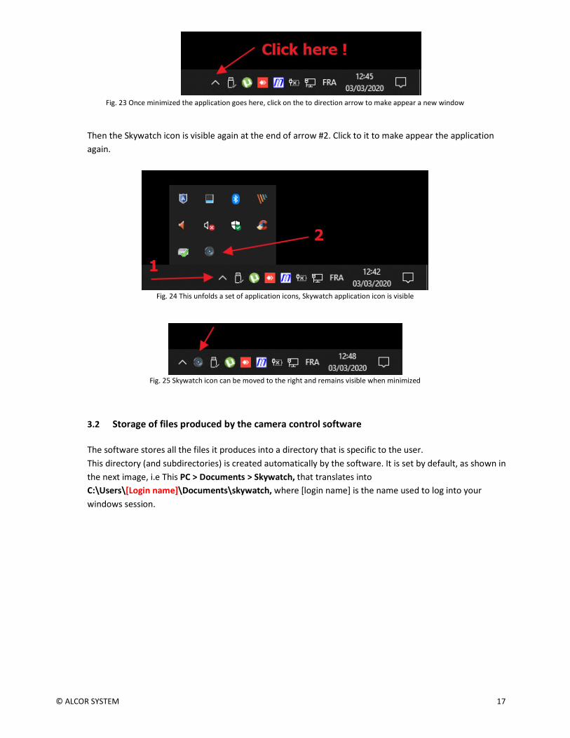
Fig. 23 Once minimized the application goes here, click on the to direction arrow to make appear a new window
Then the Skywatch icon is visible again at the end of arrow #2. Click to it to make appear the application
again.
Fig. 24 This unfolds a set of application icons, Skywatch application icon is visible
Fig. 25 Skywatch icon can be moved to the right and remains visible when minimized
3.2 Storage of files produced by the camera control software
The software stores all the files it produces into a directory that is specific to the user.
This directory (and subdirectories) is created automatically by the software. It is set by default, as shown in
the next image, i.e This PC > Documents > Skywatch, that translates into
C:\Users\[Login name]\Documents\skywatch, where [login name] is the name used to log into your
windows session.

© ALCOR SYSTEM 18
Fig. 26
• The subdirectory AVI: contains the latest videos generated by the camera control software.
• The subdirectory DarkFrames: contains the images needed for camera hot pixels removal. All CPA
files found there are tried by the software to find the best dark frame to be used to remove camera hot
pixels.
• The subdirectory FTPData: contains the final JPEG image produced to be uploaded on user’s website
• The subdirectory FTPLog: contains the log files generated for each image transfer to the website.
These logs help to find out issues when transferring files to user’s website.
• The subdirectory HotpixelsList: contains the hotpixlist.cos file used to make hot pixel corrections
that were not removed by the subtraction of the optimized dark master frame.
Hotpixlist.cos this is an ASCII file where each line describes the correction to be made to a given X/Y
pixel
For instance: fill 103 360 1 fill 289 570 1
fill 304 125 1 fill 664 326 1
The first line indicates that the pixel located at X = 103 and Y = 12 and a single pixel size shall be
corrected by its neighbors pixels.
This correction takes into account that the image is a Bayer pattern array (color camera) and picks up
neighbors pixels accordingly.
This file can be automatically generated from a feature from this software (see next paragraph)
• The Logs files subdirectory: contains the log files of the software, in which are written the software
actions and events as a text file. This is for debugging purposes. A new file is created each time you
startup the camera control software.
The log file is enabled into the main’s software setup panel.

© ALCOR SYSTEM 19
• The subdirectory Year_month_Day like 2016-06-14: contains image files that are saved
automatically by the software as jpegs files or CPA/FITS files.
The directory is used from noon to noon. For instance images created from 12:00 on May 10th 2010 till
May 11th, 2010 at 11:59 will all be stored inside 2010_05_10 subdirectory.
3.3 Camera exposure time and gain
The software has two recording modes:
3.3.1 Manual mode
The user enters the exposure time and gain as he wishes. No adjustment is made by the software.
3.3.2 Automatic mode
The software manages the exposure time with focusing on the camera gain. It is up to the user to set the
maximum gain and maximum exposure time he wants to use. The software can use a calculation area of
512x512 pixels at the center of the whole image, all the image or circular fisheye, with the aim to adjust the
gain / exposure time to get a signal level located at half the camera dynamic range. When the settings are
changed, regarding which area will be used, a red shape appear on the image during some minutes as a
reminder of the selected area.
Fig. 27

© ALCOR SYSTEM 20
Fig. 28 If the computing area for auto exposure is set to 512x512 image center, this shape is drawn to show where the bounds of this area are
located.
When determining the maximum exposure time, the user shall bear in mind that the minimum exposure
time is 32μs (0.000032 sec) and the maximum exposure time will depend on when the stars will start to
leave traces due to earth rotation.
3.4 Image hot pixel removal using dark frame image
The camera embedded in this system is not cooled sensor camera, but hot pixels can be removed thanks to
software features.
Dark frame removal is important to get rid of hot pixels and is fundamental to get good image quality.
The raw image from the camera must be completely corrected for thermal effects of the camera. These
thermal effects result in the presence of hot pixels (as bright / colored pixels). In the case of color camera
these hot pixels turns into colored dot with showing pure color (blue, red or green) that affect strongly
image quality.
Production of hot pixels depends mainly on the temperature of the CCD camera that is bound to external
temperature. More the camera is being used under conditions of high temperatures, more the amount of
© ALCOR SYSTEM 21
hot pixels. Exposure time also affects strongly the amount of hot pixels: the higher the exposure time, the
higher the number of hot pixels.
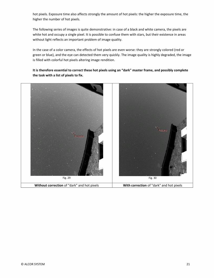
The following series of images is quite demonstrative: in case of a black and white camera, the pixels are
white hot and occupy a single pixel. It is possible to confuse them with stars, but their existence in areas
without light reflects an important problem of image quality.
In the case of a color camera, the effects of hot pixels are even worse: they are strongly colored (red or
green or blue), and the eye can detected them very quickly. The image quality is highly degraded, the image
is filled with colorful hot pixels altering image rendition.
It is therefore essential to correct these hot pixels using an “dark" master frame, and possibly complete
the task with a list of pixels to fix.
Fig. 29
Fig. 30
Without correction of "dark" and hot pixels With correction of "dark" and hot pixels

© ALCOR SYSTEM 22
Fig. 31
Fig. 32
Without correction of "dark" and hot pixels With correction of "dark" and hot pixels
The software performs hot pixels fixing in three ways:
- By subtracting a master dark frame.
- Local pixel correction from a list of hot pixels
- Automatic local hot pixel removal based on two parameters
Activation of these corrections is achieved using the main camera control panel, camera tab, then on the
following checkboxes "Remove dark frame", “Hot pixel removal” based on pixel list coordinates or / and
"Automatic hot pixel removal"
The master dark frame is located in this folder:
Fig. 33
During day, the dark frame correction is not performed, because negligible, as exposure times of
approximately 1ms to 32μs avoids hot pixels presence. This is not the case at night when the exposure time
is 600 000-750 000 times higher than during day.
If no dark file cannot be found inside this “DarkFrames” folder, if the image file does not have the same size
in width or height, or if not the same pixels type, a message error will be displayed in the status tab of the
control panel.

© ALCOR SYSTEM 23
This dark frame subtraction is performed through an optimization algorithm of the coefficient to be applied
to the master dark frame image. If many files are present, the software will select the master dark frame
that provides a result that is closest to 1.0.
Fig. 34
The software scans the presence of files in the DarkFrames folder and will automatically pick up the most
appropriate.
This means that if the master dark frame was produced at a given temperature, a given exposure time and a
given gain, the software is able to optimize the subtraction of the current image by the best dark frame,
even if there was temperature changes. This is performed within a reasonable range of variation. It will be
discussed later on the effects and validity of the dark master frame according to the variation of parameters.
As there are still hot pixels that have non-linear behavior and cannot be corrected by the dark master frame,
correction using hot pixels list can be achieved, cleaning the image of hot pixels by its neighbors.
Just check the box highlighted in the screenshot below.
Fig. 35
The file used for this operation can be found here:

© ALCOR SYSTEM 24
Fig. 36
It contains a list of hot pixels to repair/fix.
3.4.1 Achieving master dark frame
The files located into DarkFrames folder, whose fundamental purpose has been presented above, may, in
some cases no longer be adapted to the current image shooting conditions (due to seasonal temperature
changes). This is especially the temperature change that will determine the validity of the master "dark"
frame. This validity is above/below 5°C the temperature where the master dark frame has been recorded.
Beyond this temperature range, the image hot pixel repair/removal using this dark frame might become
poor and not effective.
For example, a master "dark" frame recorded from a set of some dark images at 20 ° C will be valid for
images acquired between +15 °C to +25 °C.
It is better to build a small library of "dark master" for each 5°C (outdoor temperature)
The software will automatically select the most appropriate in the “DarkFrames” folder.
How to make a master "dark" frame for a given outdoor temperature?
This is easy. Under “Camera” tab, uncheck "Auto Exposure time" and select an exposure time
corresponding to the longest exposure time used during night, for example 30s
Concerning gain, the largest gain used during night, for instance 150 (and then "Apply")
Operate during night ONLY and cover the system (the Plexiglas dome) with a black tissue, or black paper. Be
sure that any stray light cannot penetrate to the camera lens. Warning, it's a fisheye that is mounted on the
top of the camera, and it able to see 360 ° down to the horizon
A feature has been implemented to achieve a master dark frame, and also can compute a list of hot pixels
too.
Press the "Dark frame recording mode" and check "Do median stack of" say 5 to 11 "darks".

© ALCOR SYSTEM 25
Fig. 37
The software switches into a particular mode that allows it to produce "dark" frames and performs the
median stack when the amount a required dark frames have been reached in order to achieve a dark master
frame and a list of hot pixels.
Fig. 38
The resulting files are placed in the proper directories and are immediately ready for use.
Once the task is complete, click on "Normal mode"
Enable the following features by checking the following boxes:

© ALCOR SYSTEM 26
Fig. 39
For each image recorded by the camera, the dark master frame file will be used in the form:
Displayed_image = Raw_Image - ( k * Master_dark_frame_Image)
Where k is a coefficient optimized by the software.
More k is close to 1, the better. In the following scenario, k = 0.95, which is a good value.
Fig. 40
If k> 1.5 or k <0.5, it means that the master dark frame is not well appropriate to the current outdoor
temperature conditions. A warning message will be displayed as a red sentence.
3.4.2 Residual hot pixels repair/fix
Despite the subtraction by a master dark frame, and the repair of hot pixels based on a list of coordinates,
some hot pixels are still variable (appear and disappear from one frame to another). To remove these last
hot pixels that can’t be removed previously, the next checkbox shall be enabled:

© ALCOR SYSTEM 27
Fig. 41
The algorithm automatically eliminates hot pixels by inspecting all pixels from the incoming image. Two
parameters to set two conditions are necessary.
The first parameter defines the difference of the pixel compared to its eight neighbors for which that pixel will
be considered as potential hot pixels because it exceeds the defined gap (as ADU).
The second parameter sets the maximum standard deviation of the eight neighboring pixels, if the deviation
is less than the defined value; the central pixel is considered as potential hot pixel.
When the two above conditions are met, the hot pixel is fixed automatically.
Fig. 42
The figure above shows that the automatic correction is performed on average into one pixel every 69x69
pixel box. To test this feature use a moonless night, and be careful not to remove some stars of the picture
by setting a too low maximum gap and too high standard deviation !
You can see how these fixed pixels are spread over the image, by enabling the following checkbox.
Fig. 43

© ALCOR SYSTEM 28
A pixel density corrected that implies one pixel every 7x7 pixels box is maximum, beyond this density, such
as one pixel each 5x5 pixel, you will have to achieve your "dark" frame and the list of hot pixels bound to it.
3.5. Embedded Image Status information
In JPEG image, a cartridges are indicating camera statuses, "2129" indicates the number of images taken
since the software has been started up. "D 1.6" indicates a correction by a factor 1.6 of the dark frame; "H"
indicates hot pixel correction using a list, for example "18x18 H" indicates that an average of one pixel of
18x18 pixel bow is repaired. If H! is displayed, this means that the hot pixel file was not found. The “L 9x9"
indicates an automatic correction of hot pixels having an average density of 1 pixel per 9 by 9 pixels.
Fig. 44
Fig. 45
3.5 Setting the overlay grid
The camera must be installed vertically using a water “bubble” level. Otherwise, the setting of this grid
will be impossible.
Here is the recommended way to set the grid that is used to identify stars on the image: this is not an
automatic procedure, this setting shall be performed manually. But once set, this will be set forever (expect
the camera is being moved or rotated). In the Control Panel, set the location, latitude and longitude,
altitude, and the country.

© ALCOR SYSTEM 29
Fig. 46
• Use night time when a star of magnitude 0 to 3 passes to zenith (or say +/- 2° from the zenith)
• Force fixed exposure time of 5s to 10s
• Get to "Enable grid display" and "Show Main object" (Check “Only horizon”)
• Find the star that passes nearby zenith and move the cross indicating zenith towards it.
• Change “X center” and “Y center” figures so that the cross position matches with the star.

© ALCOR SYSTEM 30
Fig. 47 displacement in X and Y to adjust the position of the zenith symbol
Fig. 48 Star passing nearby zenith (Deneb) and zenith marker
• Once the zenith marker found, you have to set the "north position" to have the grid (circle and
star’s name) matching with star position. The grid scale can be changed also.
The grid (or set of stars position) is changing according to the time and geographical
coordinates. Be sure to have set theses parameters correctly.

© ALCOR SYSTEM 31
3.6 Cyanogen Boldwood or Sentinel cloud sensors link with camera control software
If you own a cloud monitor from Cyanogen or Shelyak companies, it is possible to display, at the top right of
the image, some weather information. In the main Setup Panel, enter appropriate information. The software
uses simply the output file generated by each measurement from cloud sensor. It does not use the COM or
ActiveX interface. Enter the path of the generated file provided by the software that runs the cloud sensor.
The amount of information depends on the system that is measuring cloud cover. It will be the most
complete using Sentinel Shelyak system (wind direction and zenith magnitude per second squared).
Fig. 49 group information to provide to connect with cloud sensor system control software.
© ALCOR SYSTEM 32
Fig. 50 List of information coming from Sentinel or Boltwood
cloud sensor included in the image
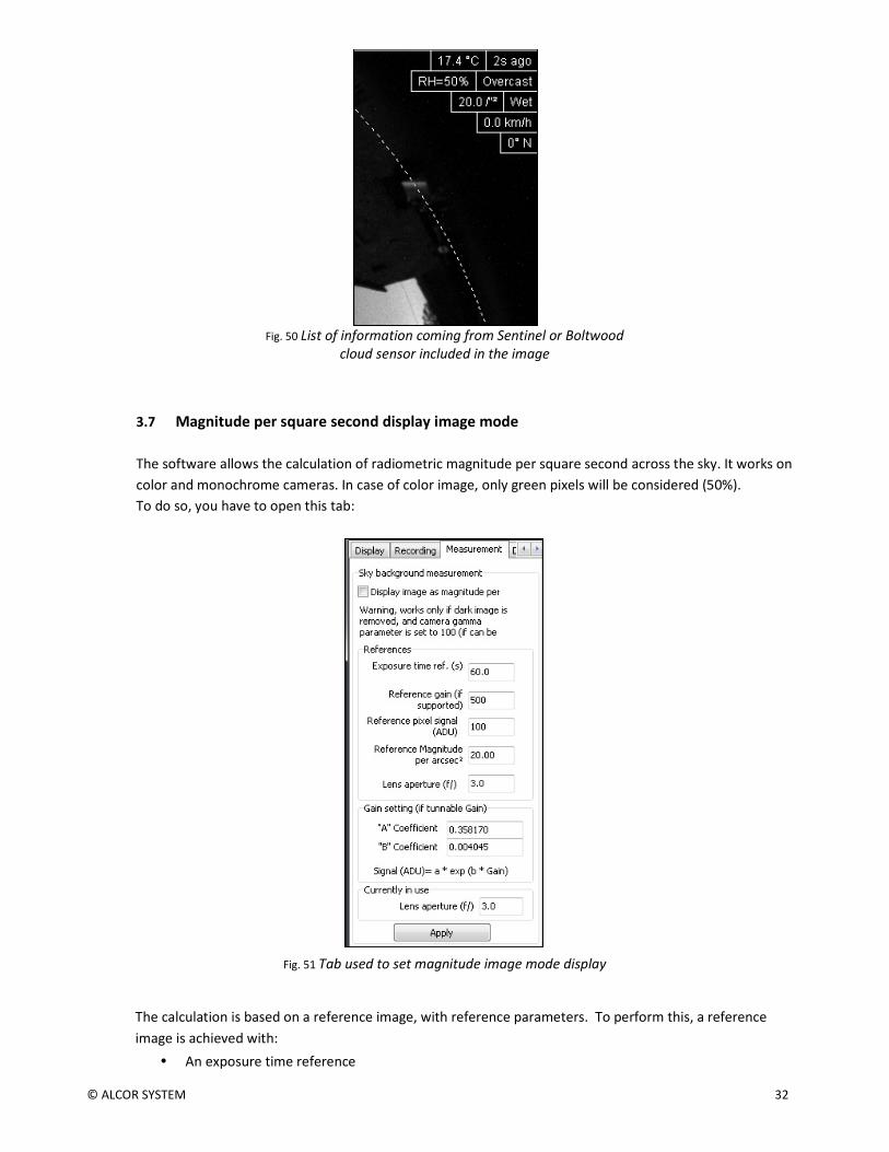
3.7 Magnitude per square second display image mode
The software allows the calculation of radiometric magnitude per square second across the sky. It works on
color and monochrome cameras. In case of color image, only green pixels will be considered (50%).
To do so, you have to open this tab:
Fig. 51 Tab used to set magnitude image mode display
The calculation is based on a reference image, with reference parameters. To perform this, a reference
image is achieved with:
• An exposure time reference

© ALCOR SYSTEM 33
• A camera gain reference
• Opening aperture reference (which is usually fixed as the aperture setting is not accessible).
• Subtracting the reference image by a master dark frame
• The camera gamma adjustment must be set to 100.
• Avoid the presence of Milky Way overhead.
• Save reference image as CPA / FITS
Using this reference image, the signal is expressed as ADU. Nearby zenith the signal is measured and is
reduced to a pixel, and must be entered in the panel from figure (Fig. 52) “Reference pixel signal” field.
It is advisable to use image processing software (such as Prism or equivalent).
At the time of reference image acquisition (during night), using a sky meter measuring device such as
Sentinel or SkyQualityMeter (Unihedron), the magnitude per square second will be retrieved and entered as
a reference “Reference Magnitude per arcsec²”.
The coefficients "A" (0358) and "B" (0.004045) are specific to the camera law gain and might remain at their
default values above, but can be re-calibrated in laboratory for a specific camera.
Once the calibration parameters known, the software calculates the magnitudes map per square second
from the last image grabbed from the camera. Median filtering is performed to remove most of the stars.
The image pixels are expressed in magnitude per square second, a false-color palette is applied and a color
scale indicates the color to magnitude correlation.
Fig. 53 Map of the sky expressed as magnitudes per arcsec square with false colors.
© ALCOR SYSTEM 34
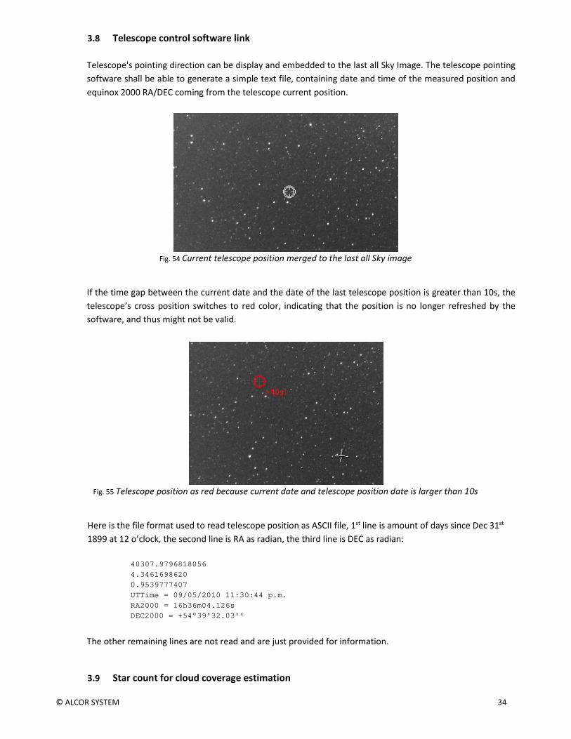
3.8 Telescope control software link
Telescope's pointing direction can be display and embedded to the last all Sky Image. The telescope pointing
software shall be able to generate a simple text file, containing date and time of the measured position and
equinox 2000 RA/DEC coming from the telescope current position.
Fig. 54 Current telescope position merged to the last all Sky image
If the time gap between the current date and the date of the last telescope position is greater than 10s, the
telescope’s cross position switches to red color, indicating that the position is no longer refreshed by the
software, and thus might not be valid.
Fig. 55 Telescope position as red because current date and telescope position date is larger than 10s
Here is the file format used to read telescope position as ASCII file, 1st line is amount of days since Dec 31st
1899 at 12 o’clock, the second line is RA as radian, the third line is DEC as radian:
40307.9796818056
4.3461698620
0.9539777407
UTTime = 09/05/2010 11:30:44 p.m.
RA2000 = 16h36m04.126s
DEC2000 = +54°39'32.03''
The other remaining lines are not read and are just provided for information.
3.9 Star count for cloud coverage estimation

© ALCOR SYSTEM 35
During the night, the software is able to extract stars, and count them up. Thresholds can be applied to define
what is regarded as clear skies, or mid overcast skies. The software output this data either into a text file, or
uses a COM interface that can be used by other any software.
Fig. 56
Star extracted are plotted into the image.
3.10 24h overview
This can be reached by activating this tab:
Fig. 57
During the course of the time, the software picks an image stripe located at the center of the fisheye field,
and duplicates it into another image that has the same height of the previous image, but this stripe is shifted
according to the time, and build up a global image where X axis depicts time.
It allows the user to see how the sky has changed during the course of the time, in a single glance. In the
image sample, it can be noticed that the end of the night was not clear and the star to disappear under a thin
layer of clouds. It goes over the left side of the image on next noon.

© ALCOR SYSTEM 36
Fig. 58 : 24h image overview construction scheme
Fig. 59 : Resulting image

© ALCOR SYSTEM 37
Fig. 60 : Previous image zoom to the end of the night, star are visible then sky clear up with dawn.

© ALCOR SYSTEM 38
4 Sphere condensation and heating management
4.1 Introduction
The heating of the sphere is achieved throughout a set of resistors placed under the sphere base. It can
defog the outside side of the acrylic sphere.
In the ALPHEA cameras, the system is not autonomous, and is enabled and disabled only by the PC software
(Skywatch), and stops during the day.
4.2 Adjusting and start-up
Use the menu "Options / ALPHEA Camera dome heating control" from the camera software main’s menu.
Fig. 61
Fig. 62 Camera temperature evolution during the course of the time.

© ALCOR SYSTEM 39
This window appears, and provides camera temperature (sensor placed near by the image sensor).
The software records the data and curves are constructed progressively (if the “Close forever” is not pressed).
Beware, if this window is “closed forever”, recording data cannot occur anymore. We recommend that you
simply hide it. Heater activation/deactivation is achieved by the PC software, not by the camera itself.
If the checkbox “Enable heating (only night time)” is set, it will activate the dome heating, only during night
time that is defined by the PC software SKYWATCH. Keep in mind that the injected heat is very moderate
(few watts) and it will overcome to defog the acrylic sphere only. It will not overcome deicing. When heating
is enabled the camera temperature increase a bit.
To get an automated defrost/defog/deicing camera dome, please see OMEA camera or EUDA camera that
can perform this task, by monitoring outside conditions and injecting up to 40W of heat.
5 Camera maintenance
6.1 Sphere cleaning
Sphere cleaning must be achieved on regular basis. Rains can bring dust that is deposited on the sphere
surface; it reduces the optical transmission and image quality.
The acrylic sphere outer and inner surface can be cleaned with water, then with a Kleenex moistened with
washer fluid dedicated for window cleaning. The 8 screws can be removed to detach the sphere from the
rest of the camera. Attention must be paid on these topics:
• O-rings properly must absolutely be positioned in their grooves
• 8 screws must be put together with their washer and all tightened the same way.
Incorrect reassembly can cause loss of sealing, allowing rain to enter and de facto guarantees no longer apply.
If you feel confident with dismounting sphere, please do not do it.
6.2 Camera internal desiccant replacement
Inside the camera, a small desiccant bag has been installed. This is molecular sieve that can set the level of
humidity down to zero. Replacement of this bag, may happen once every 3 years. If the dome is removed,
desiccants bags efficiency is nulled, and it must be replaced prior dome reassembly.
Desiccant bags prevents dew from forming in the inner side of the dome.
6 Trouble shooting
This section aims at providing hints to solve issues.
© ALCOR SYSTEM 40
6.1 Camera does not deliver images
The USB port driver might be outdated, please update USB port driver. Also change USB port on your PC,
sometime some USB are slightly damaged (ESD) with the course of the time.
If the issue persists please contact us, the long 20 m USB extender cable might be also damaged, check that
no damage has occurred on this cable (no small animal has started to eat the USB cable for instance, or
lightening has not hit the camera).
6.2 Dew inside the dome
This may happen after several year of operation, if the internal desiccant is exhausted. Please check the
internal humidity figure. To replace the internal desiccant, please contact us to get the procedure.
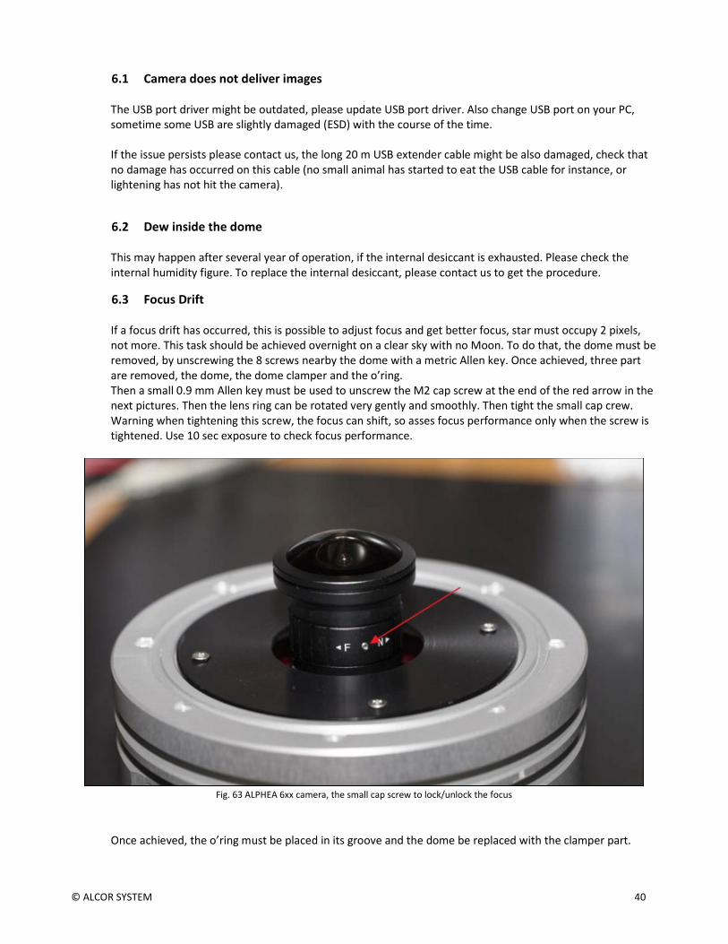
6.3 Focus Drift
If a focus drift has occurred, this is possible to adjust focus and get better focus, star must occupy 2 pixels,
not more. This task should be achieved overnight on a clear sky with no Moon. To do that, the dome must be
removed, by unscrewing the 8 screws nearby the dome with a metric Allen key. Once achieved, three part
are removed, the dome, the dome clamper and the o’ring.
Then a small 0.9 mm Allen key must be used to unscrew the M2 cap screw at the end of the red arrow in the
next pictures. Then the lens ring can be rotated very gently and smoothly. Then tight the small cap crew.
Warning when tightening this screw, the focus can shift, so asses focus performance only when the screw is
tightened. Use 10 sec exposure to check focus performance.
Fig. 63 ALPHEA 6xx camera, the small cap screw to lock/unlock the focus
Once achieved, the o’ring must be placed in its groove and the dome be replaced with the clamper part.

© ALCOR SYSTEM 41
Fig. 64 ALPHEA 3xx camera, the small cap screw to lock/unlock the focus.
The 8 screws are put back, and tightened strongly. Caution: if the o’ring seal is forgotten or badly placed, the
tightness of the camera to water may be jeopardized. So pay attention with the o’ring, and do not hesitate
to put grease on it before installation into its groove.
7 Product terms of use
The use of this product is solely for monitoring the sky, night and day, entertaining, educational or scientific
purposes.
Use of this product involving people's lives is the responsibility of the user and in no way ALCOR SYSTEM will
be held liable for injuries to persons or property theft as the use of this camera described in this manual.
---0O0---