Embed Size (px)
Citation preview
AlphaServer DS20
User’s Guide
Order Number: EK–AS140–UG. A01
This manual is for anyone who manages, operates, or services theCompaq AlphaServer DS20 system. It covers operation, firmware,initial troubleshooting, and component installation.
Compaq Computer Corporation
NoticeThe information in this publication is subject to change without notice.
COMPAQ COMPUTER CORPORATION SHALL NOT BE LIABLE FOR TECHNICALOR EDITORIAL ERRORS OR OMISSIONS CONTAINED HEREIN, NOR FORINCIDENTAL OR CONSEQUENTIAL DAMAGES RESULTING FROM THEFURNISHING, PERFORMANCE, OR USE OF THIS MATERIAL.
This publication contains information protected by copyright. No part of this publication maybe photocopied or reproduced in any form without prior written consent from CompaqComputer Corporation.
The software described in this document is furnished under a license agreement ornondisclosure agreement and may be used or copied only in accordance with the terms of theagreement.
© 1998 Compaq Computer Corporation.
All rights reserved. Printed in the U.S.A.
COMPAQ and the Compaq logo are trademarks or registered trademarks of CompaqComputer Corporation. AlphaServer, DIGITAL, OpenVMS, and StorageWorks aretrademarks or registered trademarks of Digital Equipment Corporation. Microsoft, Windows,and Windows NT are registered trademarks of Microsoft Corporation. UNIX is a registeredtrademark in the U.S. and other countries, licensed exclusively through X/Open Company Ltd.Other product names mentioned herein may be trademarks and/or registered trademarks oftheir respective companies.
Digital Equipment Corporation now owned by Compaq Computer Corporation.
FCC Notice: The equipment described in this manual generates, uses, and may emit radiofrequency energy. The equipment has been type tested and found to comply with the limits fora Class A digital device pursuant to Part 15 of FCC Rules, which are designed to providereasonable protection against such radio frequency interference. Operation of this equipmentin a residential area may cause interference, in which case the user at his own expense will berequired to take whatever measures are required to correct the interference.
Shielded Cables: If shielded cables have been supplied or specified, they must be used on thesystem in order to maintain international regulatory compliance.
Warning! This is a Class A product. In a domestic environment this product may cause radiointerference, in which case the user may be required to take adequate measures.
Achtung! Dieses ist ein Gerät der Funkstörgrenzwertklasse A. In Wohnbereichen können beiBetrieb dieses Gerätes Rundfunkstörungen auftreten, in welchen Fällen der Benutzer fürentsprechende Gegenmaßnahmen verantwortlich ist.
Avertissement! Cet appareil est un appareil de Classe A. Dans un environnement résidentiel,cet appareil peut provoquer des brouillages radioélectriques. Dans ce cas, il peut être demandéà l'utilisateur de prendre les mesures appropriées.
iii
Contents
Preface ............................................................................................................... xi
Chapter 1 Overview1.1 System Architecture.................................................................................1-21.2 System Features .......................................................................................1-41.3 Front Panel Controls and Indicators .........................................................1-61.4 Rear Panel Ports and Slots .......................................................................1-81.5 Console Terminal................................................................................... 1-101.6 Options .................................................................................................. 1-12
Chapter 2 Installing the System2.1 System Setup Overview ...........................................................................2-12.2 Selecting a Location ................................................................................2-12.3 Environmental Requirements ...................................................................2-22.4 Power Requirements ................................................................................2-32.5 Acoustical Data........................................................................................2-42.6 System Accessories..................................................................................2-52.7 Connecting the System.............................................................................2-62.8 Connecting to Network Hardware ............................................................2-72.9 Locking the System .................................................................................2-8
Chapter 3 Operation3.1 Powering Up the System ..........................................................................3-23.2 Power-Up Display....................................................................................3-43.3 Booting DIGITAL UNIX.........................................................................3-63.4 Installing DIGITAL UNIX..................................................................... 3-103.5 Booting OpenVMS ................................................................................ 3-123.6 Installing OpenVMS .............................................................................. 3-183.7 Booting Windows NT ............................................................................ 3-203.8 Installing Windows NT .......................................................................... 3-223.9 Switching Between Operating Systems .................................................. 3-243.9.1 Switching from DIGITAL UNIX or OpenVMS to Windows NT ..... 3-243.9.2 Switching from Windows NT to DIGITAL UNIX or OpenVMS ..... 3-253.10 Updating Firmware ................................................................................ 3-263.10.1 Updating Firmware from the CD-ROM........................................... 3-28
iv
3.10.2 Updating Firmware from Floppy Disk — Creating the Diskettes..... 3-323.10.3 Updating Firmware from Floppy Disk — Performing the Update.... 3-343.10.4 Updating Firmware from a Network Device.................................... 3-383.10.5 LFU Commands.............................................................................. 3-423.11 Hard Disk Partitioning ........................................................................... 3-453.11.1 Hard Disk Error Conditions............................................................. 3-453.11.2 System Partitions ............................................................................ 3-463.11.3 How AlphaBIOS Works with System Partitions .............................. 3-473.12 Using the Halt Button ............................................................................ 3-483.13 Halt Assertion ........................................................................................ 3-49
Chapter 4 SRM Console4.1 Invoking the SRM Console......................................................................4-24.2 Command Summary ................................................................................4-34.3 Displaying the System Configuration.......................................................4-84.4 Creating a Power-Up Script ................................................................... 4-154.5 Booting the Operating System................................................................ 4-174.6 Configuring the System.......................................................................... 4-194.6.1 Configuring DSSI............................................................................ 4-194.6.2 Configuring a PCI NVRAM Module............................................... 4-214.6.3 Configuring the ISA Bus................................................................. 4-224.7 Testing the System................................................................................. 4-244.8 Making the System Secure..................................................................... 4-264.9 Stopping and Starting CPUs................................................................... 4-314.10 Updating Firmware ................................................................................ 4-334.11 Forcing a System Crash Dump............................................................... 4-354.12 Using Environment Variables ................................................................ 4-364.13 Depositing and Examining Data............................................................. 4-394.14 Reading a File........................................................................................ 4-424.15 Initializing the System ........................................................................... 4-434.16 Finding Help.......................................................................................... 4-454.17 Switching from SRM to AlphaBIOS Console......................................... 4-464.18 Environment Variable Summary ............................................................ 4-47
Chapter 5 AlphaBIOS Console5.1 Starting AlphaBIOS.................................................................................5-25.2 Keyboard Conventions and Help..............................................................5-45.3 Displaying the System Configuration.......................................................5-65.3.1 System Board Configuration .............................................................5-85.3.2 Hard Disk Configuration ................................................................. 5-105.3.3 PCI Configuration ........................................................................... 5-125.3.4 Memory Configuration.................................................................... 5-15
v
5.3.5 SCSI Configuration......................................................................... 5-165.3.6 Integrated Peripherals...................................................................... 5-185.4 Updating Firmware ................................................................................ 5-205.5 Setting Up the Hard Disk ....................................................................... 5-225.5.1 Creating and Deleting Partitions Manually...................................... 5-245.5.2 Formatting a FAT Partition ............................................................. 5-265.6 Performing Setup Tasks ......................................................................... 5-285.7 Installing Windows NT .......................................................................... 5-325.8 Selecting the Version of Windows NT ................................................... 5-345.8.1 Designating a Primary Operating System ........................................ 5-365.8.2 Primary Operating System and the Auto Start Option...................... 5-385.9 Switching from AlphaBIOS to SRM Console......................................... 5-425.10 Running Utility Programs ...................................................................... 5-445.10.1 Running Utilities from a Graphics Monitor ..................................... 5-455.10.2 Running Utilities from a Serial Terminal ........................................ 5-46
Chapter 6 Managing the System Remotely6.1 RCM Overview........................................................................................6-26.2 First-Time Setup ......................................................................................6-36.2.1 Dialing In and Invoking RCM...........................................................6-46.2.2 Using RCM Locally or with a Modem on COM1 ..............................6-56.3 RCM Commands .....................................................................................6-66.4 Using the RCM Switchpack ................................................................... 6-126.5 Troubleshooting Guide........................................................................... 6-166.6 Modem Dialog Details ........................................................................... 6-17
Chapter 7 Installing Components7.1 Preparing to Install or Remove Components ............................................7-27.2 Top Cover and Side Panel Removal and Replacement .............................7-47.3 Installing a CPU Module..........................................................................7-87.4 Installing a Memory DIMM Option ....................................................... 7-107.5 Installing a PCI or ISA Card .................................................................. 7-12
Chapter 8 Troubleshooting8.1 System Does Not Power Up .....................................................................8-2
Appendix A SCSI Bus ConfigurationsA.1 Single-Bus Configurations ...................................................................... A-2A.2 Split-Bus Configuration .......................................................................... A-4
Index
vi
Examples3–1 Power-Up Display....................................................................................3-43–2 Booting DIGITAL UNIX from a Local Disk............................................3-63–3 Booting DIGITAL UNIX from a Remote Disk.........................................3-83–4 Installing DIGITAL UNIX..................................................................... 3-103–5 Booting OpenVMS from a Local Disk ................................................... 3-123–6 Booting OpenVMS from a Disk on a Cluster ......................................... 3-143–7 Booting OpenVMS from a Remote Disk ................................................ 3-163–8 Installing OpenVMS .............................................................................. 3-183–9 Starting LFU from the SRM Console ..................................................... 3-263–10 Booting LFU from the CD-ROM........................................................... 3-273–11 Updating Firmware from the CD-ROM.................................................. 3-283–12 Creating Update Diskettes on an OpenVMS System.............................. 3-333–13 Updating Firmware from the Internal Floppy Disk................................. 3-343–14 Selecting AS4X00FW to Update Firmware from the Internal
Floppy Disk........................................................................................... 3-373–15 Updating Firmware from a Network Device........................................... 3-384–1 Show Config Command...........................................................................4-84–2 Show CPU Command ..............................................................................4-94–3 Show Device Command......................................................................... 4-104–4 Show Memory Command ...................................................................... 4-124–5 Show PAL Command ............................................................................ 4-124–6 Show Power Command.......................................................................... 4-134–7 Show Version Command........................................................................ 4-144–8 Editing the nvram Script ........................................................................ 4-154–9 Clearing the nvram Script ...................................................................... 4-154–10 Boot Command...................................................................................... 4-174–11 Set Host Command................................................................................ 4-194-12 Prcache Command ................................................................................. 4-214-13 Isacfg Command.................................................................................... 4-224-14 Test Command....................................................................................... 4-244-15 Set Password Command......................................................................... 4-264-16 Set Secure Command............................................................................. 4-274-17 Login Command .................................................................................... 4-284-18 Clear Password Command ..................................................................... 4-304-19 Halt, and Continue Commands............................................................... 4-314-20 Lfu Command........................................................................................ 4-334-21 Crash Command .................................................................................... 4-354-22 Set envar and Show envar Commands ................................................... 4-364–23 Creating a User-Defined Environment Variable..................................... 4-384-24 Deposit Command ................................................................................. 4-39
vii
4-25 Examine Command................................................................................ 4-394-26 More Command ..................................................................................... 4-424-27 Initialize Command ............................................................................... 4-434-28 Help Command...................................................................................... 4-454-29 Switching to the AlphaBIOS Console .................................................... 4-466–1 Sample Remote Dial-In Dialog................................................................6-46–2 Invoking and Leaving RCM Locally........................................................6-5
Figures1–1 System Architecture.................................................................................1-21–2 Front Panel Controls and Indicators .........................................................1-61–3 Rear Panel Ports and Slots .......................................................................1-81–4 Storage Option Compartments ............................................................... 1-122–1 System Dimensions and Service Area ......................................................2-22–2 Power Supply Requirements....................................................................2-32–3 System Accessories..................................................................................2-52–4 System Connections.................................................................................2-62–5 Network Connections...............................................................................2-72–6 System Lock and Key ..............................................................................2-83–1 Location of On/Off Switch.......................................................................3-23–2 AlphaBIOS Boot Screen ........................................................................ 3-203–3 Installing Windows NT.......................................................................... 3-223–4 Starting LFU from the AlphaBIOS Console ........................................... 3-263–5 System Partition Not Defined................................................................. 3-475–1 Boot Screen .............................................................................................5-25–2 AlphaBIOS Setup Screen .........................................................................5-35–3 Typical First-Level Help Screen ..............................................................5-45–4 Second-Level Help Screen.......................................................................5-55–5 Display System Configuration Screen ......................................................5-65–6 System Board Configuration ....................................................................5-85–7 Hard Disk Configuration........................................................................ 5-105–8 PCI Configuration.................................................................................. 5-125–9 Advanced PCI Information .................................................................... 5-145–10 Memory Configuration........................................................................... 5-155–11 SCSI Configuration................................................................................ 5-165–12 Integrated Peripherals............................................................................ 5-185–13 Updating Firmware................................................................................ 5-205–14 Hard Disk Setup Screen......................................................................... 5-225–15 Create New Partition Dialog Box........................................................... 5-245–16 Delete Partition Dialog Box................................................................... 5-255–17 Formatting a FAT Partition.................................................................... 5-265–18 Standard Formatting............................................................................... 5-27
viii
5–19 Standard CMOS Setup Screen................................................................ 5-285–20 Advanced CMOS Setup Screen.............................................................. 5-305–21 Installing Windows NT.......................................................................... 5-325–22 Operating System Selections.................................................................. 5-345–23 Primary Operating System..................................................................... 5-365–24 Operating System Selection Setup.......................................................... 5-385–25 Switching to the SRM Console.............................................................. 5-425–26 Run Maintenance Program Dialog Box.................................................. 5-445–27 AlphaBIOS Utilities Menu..................................................................... 5-456-1 RCM Connections....................................................................................6-36-2 Location of RCM Switchpack on Server Control Module....................... 6-126-3 RCM Switches (Factory Settings) .......................................................... 6-137–1 Attaching the Antistatic Wrist Strap.........................................................7-37–2 Removing Top Cover and Side Panels .....................................................7-47–3 Replacing Top Cover and Side Panels......................................................7-67–4 CPU Module Slots...................................................................................7-87–5 CPU Module Installation..........................................................................7-97–6 Memory Slots on System Board ............................................................. 7-107–7 Memory Card Installation ...................................................................... 7-117–9 PCI and ISA Slots .................................................................................. 7-127–10 PCI/ISA Card Installation...................................................................... 7-138–1 Location of Cover Interlock .....................................................................8-2A–1 Single-Bus Configuration (One Multi-Channel Controller) ..................... A-2A–2 Single-Bus Configuration (Two Single-Channel Controllers) .................. A-3A–3 Split-Bus Configuration .......................................................................... A-4
ix
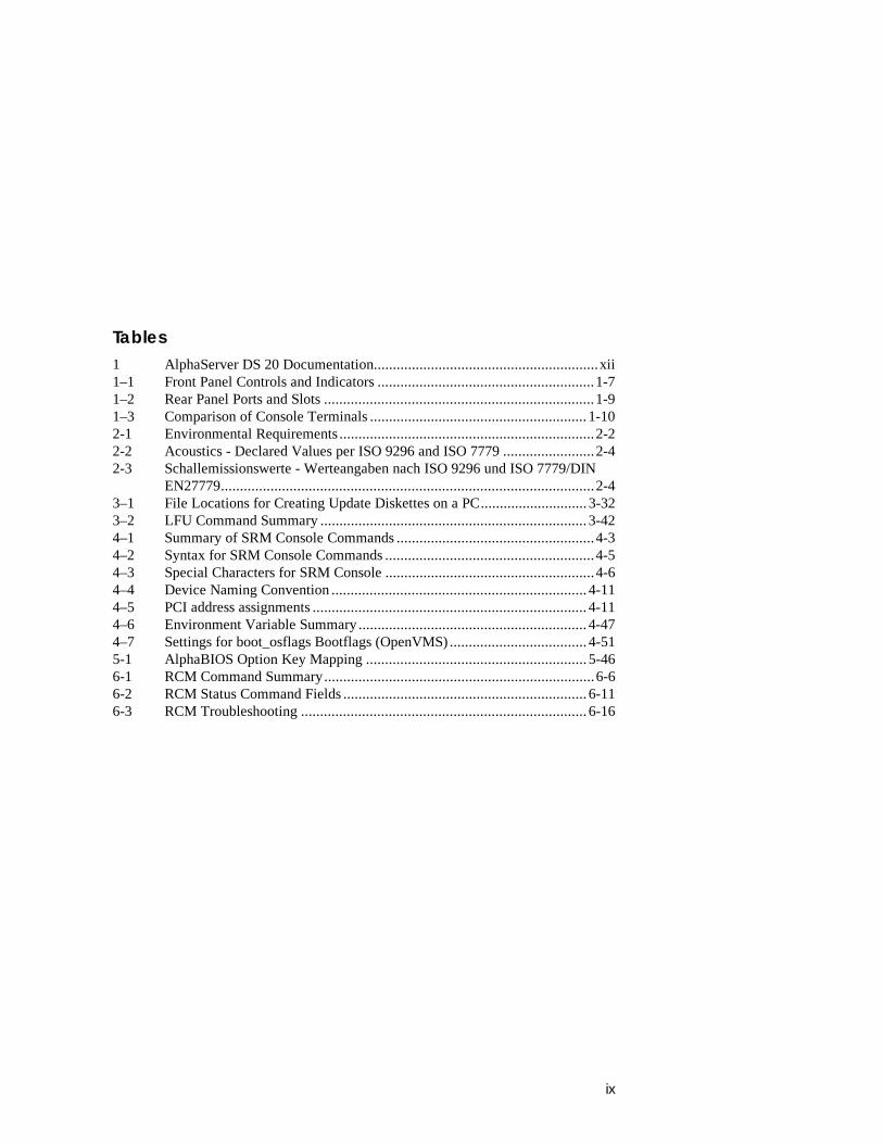
Tables1 AlphaServer DS 20 Documentation...........................................................xii1–1 Front Panel Controls and Indicators .........................................................1-71–2 Rear Panel Ports and Slots .......................................................................1-91–3 Comparison of Console Terminals ......................................................... 1-102-1 Environmental Requirements...................................................................2-22-2 Acoustics - Declared Values per ISO 9296 and ISO 7779........................2-42-3 Schallemissionswerte - Werteangaben nach ISO 9296 und ISO 7779/DIN
EN27779..................................................................................................2-43–1 File Locations for Creating Update Diskettes on a PC............................ 3-323–2 LFU Command Summary ...................................................................... 3-424–1 Summary of SRM Console Commands ....................................................4-34–2 Syntax for SRM Console Commands .......................................................4-54–3 Special Characters for SRM Console .......................................................4-64–4 Device Naming Convention................................................................... 4-114–5 PCI address assignments ........................................................................ 4-114–6 Environment Variable Summary ............................................................ 4-474–7 Settings for boot_osflags Bootflags (OpenVMS).................................... 4-515-1 AlphaBIOS Option Key Mapping .......................................................... 5-466-1 RCM Command Summary.......................................................................6-66-2 RCM Status Command Fields ................................................................ 6-116-3 RCM Troubleshooting........................................................................... 6-16

xi
Preface
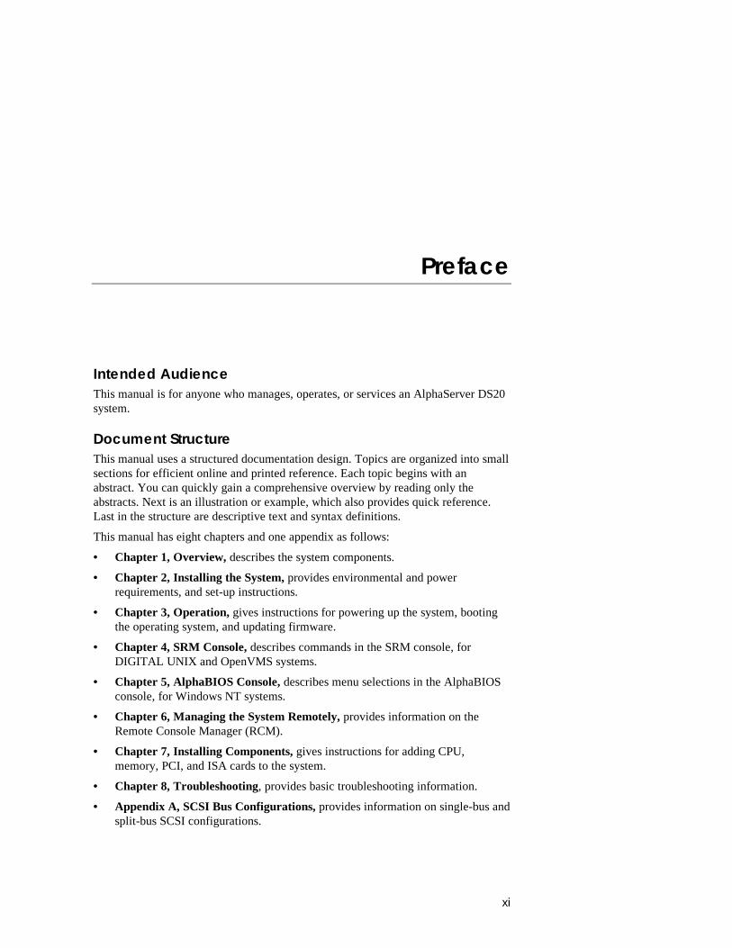
Intended AudienceThis manual is for anyone who manages, operates, or services an AlphaServer DS20system.
Document StructureThis manual uses a structured documentation design. Topics are organized into smallsections for efficient online and printed reference. Each topic begins with anabstract. You can quickly gain a comprehensive overview by reading only theabstracts. Next is an illustration or example, which also provides quick reference.Last in the structure are descriptive text and syntax definitions.
This manual has eight chapters and one appendix as follows:
• Chapter 1, Overview, describes the system components.
• Chapter 2, Installing the System, provides environmental and powerrequirements, and set-up instructions.
• Chapter 3, Operation, gives instructions for powering up the system, bootingthe operating system, and updating firmware.
• Chapter 4, SRM Console, describes commands in the SRM console, forDIGITAL UNIX and OpenVMS systems.
• Chapter 5, AlphaBIOS Console, describes menu selections in the AlphaBIOSconsole, for Windows NT systems.
• Chapter 6, Managing the System Remotely, provides information on theRemote Console Manager (RCM).
• Chapter 7, Installing Components, gives instructions for adding CPU,memory, PCI, and ISA cards to the system.
• Chapter 8, Troubleshooting, provides basic troubleshooting information.
• Appendix A, SCSI Bus Configurations, provides information on single-bus andsplit-bus SCSI configurations.
xii
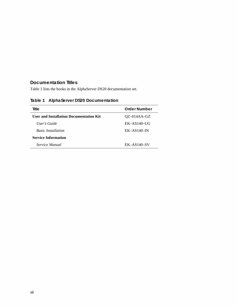
Documentation TitlesTable 1 lists the books in the AlphaServer DS20 documentation set.
Table 1 AlphaServer DS20 Documentation
Title Order Number
User and Installation Documentation Kit QZ–014AA–GZ
User’s Guide EK–AS140–UG
Basic Installation EK–AS140–IN
Service Information
Service Manual EK–AS140–SV
Overview 1-1
Chapter 1
Overview
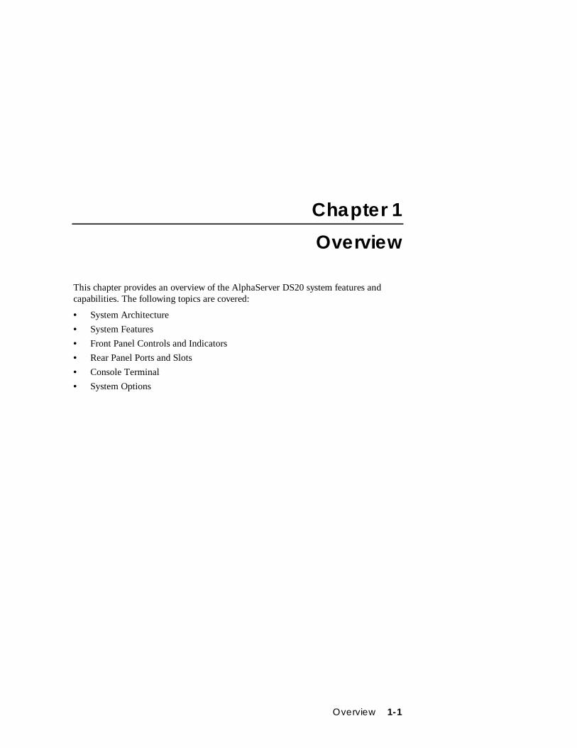
This chapter provides an overview of the AlphaServer DS20 system features andcapabilities. The following topics are covered:
• System Architecture
• System Features
• Front Panel Controls and Indicators
• Rear Panel Ports and Slots
• Console Terminal
• System Options
1-2 AlphaServer DS20 User’s Guide
1.1 System Architecture
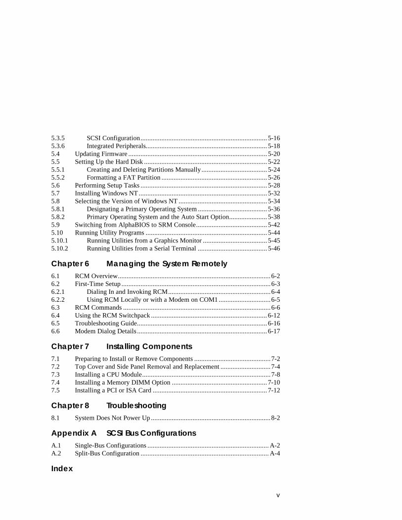
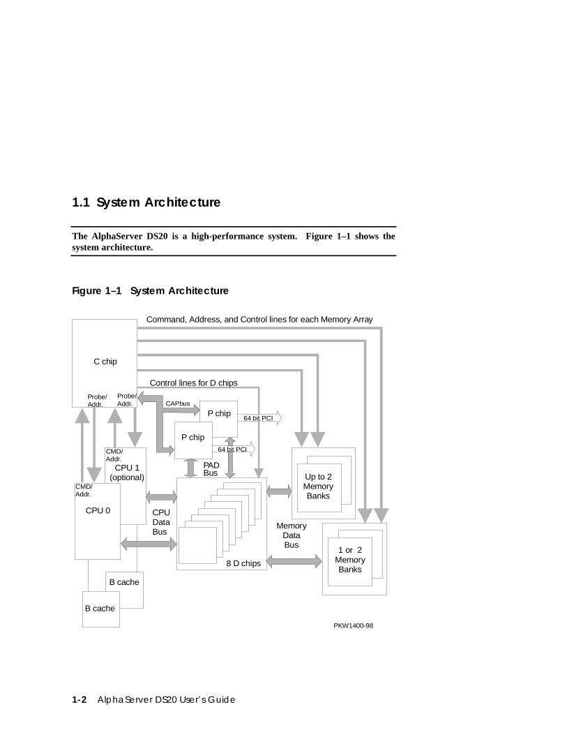
The AlphaServer DS20 is a high-performance system. Figure 1–1 shows thesystem architecture.
Figure 1–1 System Architecture
C chip
CPU 1(optional)
CPU 0
B cache
B cache
8 D chips
P chip
P chip
1 or 2MemoryBanks
Up to 2MemoryBanks
64 bit PCI
64 bit PCI
Command, Address, and Control lines for each Memory Array
Control lines for D chips
MemoryDataBus
CPUDataBus
CAPbus
PADBus
CMD/Addr.
CMD/Addr.
Probe/Addr.
Probe/Addr.
PKW1400-98
Overview 1-3
The AlphaServer DS20 is a switch-based interconnect system using a cross-barswitch chipset that allows data to move directly from place to place in the system.Figure 1–1 is a block diagram showing the various data paths through the switch.The pedestal enclosure contains the system and allows for up to ten internal storagedevices: one dedicated diskette drive slot, two removable media slots, and seven 3.5-inch hard disk drives. All CPUs, memory and I/O components are on a single boardthat contains the memory subsystem, two PCI buses, the ISA bus, the integrated I/Ocontrollers. The remote console manager (RCM) is on a separate server featuremodule.
The control panel includes Halt, Reset, and On/Off buttons.
Supported Operating Systems
This system supports the following minimum revisions of these operating systems:
• Microsoft Windows NT 4.0 with service pack 3 or later
• OpenVMS 7.1-2
• DIGITAL UNIX 4.0E
The system runs in two modes. In program mode, the operating system controls thesystem and manages the execution of application programs. In console mode, theconsole program controls the system allowing control of system managementfunctions.
System Console Firmware
You perform many of the tasks for managing and configuring your server system inconsole mode, where the system is controlled by the console subsystem, rather thanthe operating system.
The console subsystem, located in ROM (read-only memory) on the system board,contains the firmware that interacts directly with hardware components andfacilitates interaction between the hardware and the operating system.
1-4 AlphaServer DS20 User’s Guide
1.2 System Features
The system provides a number of features that enhance its reliability andimprove its expansion capabilities, as well as facilitate hardware managementand improve security.
Reliability• 64-bit Alpha architecture Provides significantly better performance than
32-bit architecture.
• Error correction code (ECC)on memory and CPU cache
Allows recovery from most cache and memoryerrors.
• Variable fan speed Adjusts fan speed according to systemtemperature.
• Integral Remote ConsoleManagement (RCM) function
Enables remote access to system.
• Internal sensors Monitor and detect internal system temperature,fan failure, power supply temperature.
• Hot swap disk capability Allows replacement of StorageWorks disk driveswhile the system continues to operate.
• Redundant power A single power supply can run a fully configuredsystem. An optional second power supply can beadded to provide sufficient power for the systemto continue to run even if one supply should fail.
System Expansion• Flexible memory
architecture.System memory can be expanded from 128 MB to4 GB.
• Six PCI expansion slots.One PCI slot can be used asan ISA slot instead.
Accommodates industry-standard option cardssuch as Ethernet, FDDI, and SCSI devices.
• Dual-ported integratedUltraSCSI controller
Supports tape, disks, and CD-ROM without use ofan expansion slot.
Overview 1-5
• Capacity for 10 internalstorage devices
Accommodates one StorageWorks modularstorage system, which supports up to seven 3½-inch UltraSCSI drives. Also supports up to two5½-inch, half-height drives (CD-ROM or tape),and one 3½-inch diskette.
• External ports Two serial ports and one parallel port supportexternal options such as a printer, modem, orlocal terminal.
• UltraSCSI storage drive Supports up to 7 high-performance drivetechnology.
System Management• System diagnostics Allow local and remote diagnosis of system
problems.
• Hardware configuration Allows local and remote system configuration.
• Unique asset management Unique system identifier in nonvolatile memoryprovides easy asset management.
• RAM-based error log Records startup error messages.
• Firmware upgrade utility Provides loading and verification of firmwareversions.
• Environmental failure eventslogged in NVRAM
Provides troubleshooting information for systemshutdowns.
• Hard drive indicator lights Provide immediate status information on harddrive activity or fault indication.
System Security• Key lock Limits access to system components.
• Security loop (on rear ofsystem unit)
Allows system to be secured in place.
• Interlock sensor switch Automatically turns off system power if the topcover is removed while power is on.
1-6 AlphaServer DS20 User’s Guide
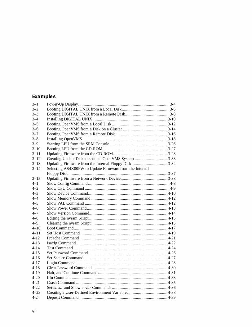
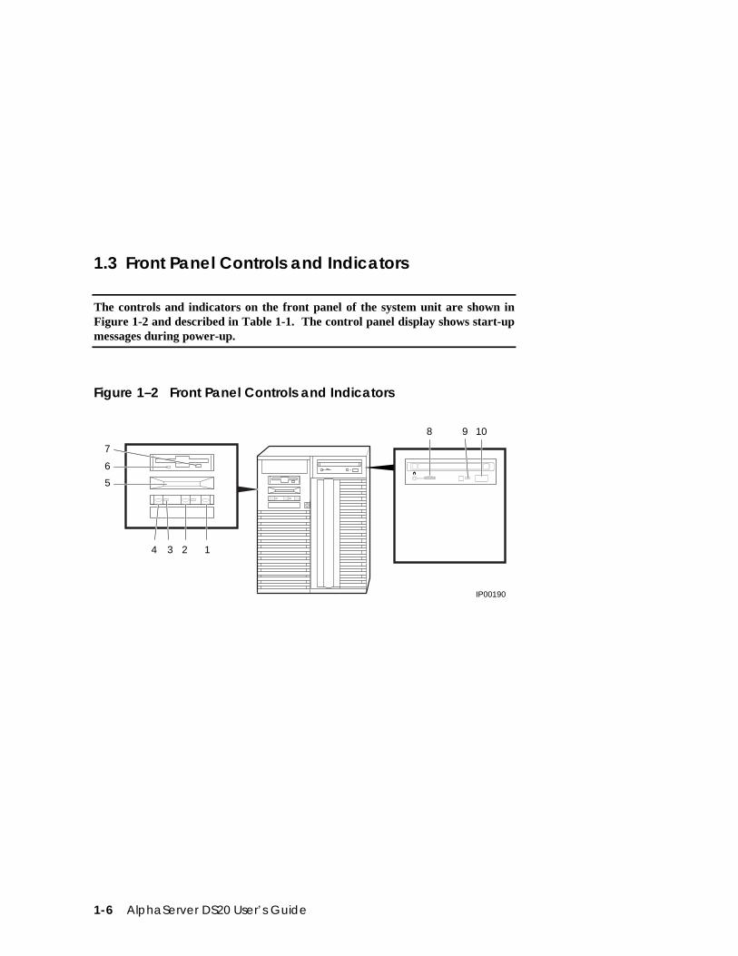
1.3 Front Panel Controls and Indicators
The controls and indicators on the front panel of the system unit are shown inFigure 1-2 and described in Table 1-1. The control panel display shows start-upmessages during power-up.
Figure 1–2 Front Panel Controls and Indicators
4 3 2 1
7
6
5
IP00190
8 9 10
Overview 1-7
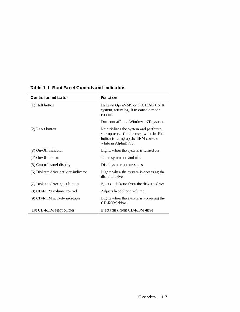
Table 1-1 Front Panel Controls and Indicators
Control or Indicator Function
(1) Halt button Halts an OpenVMS or DIGITAL UNIXsystem, returning it to console modecontrol.
Does not affect a Windows NT system.
(2) Reset button Reinitializes the system and performsstartup tests. Can be used with the Haltbutton to bring up the SRM consolewhile in AlphaBIOS.
(3) On/Off indicator Lights when the system is turned on.
(4) On/Off button Turns system on and off.
(5) Control panel display Displays startup messages.
(6) Diskette drive activity indicator Lights when the system is accessing thediskette drive.
(7) Diskette drive eject button Ejects a diskette from the diskette drive.
(8) CD-ROM volume control Adjusts headphone volume.
(9) CD-ROM activity indicator Lights when the system is accessing theCD-ROM drive.
(10) CD-ROM eject button Ejects disk from CD-ROM drive.
1-8 AlphaServer DS20 User’s Guide
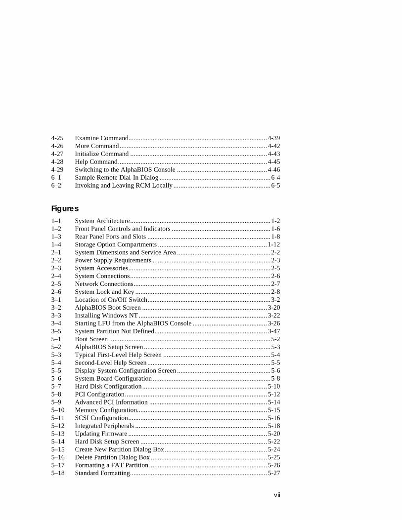
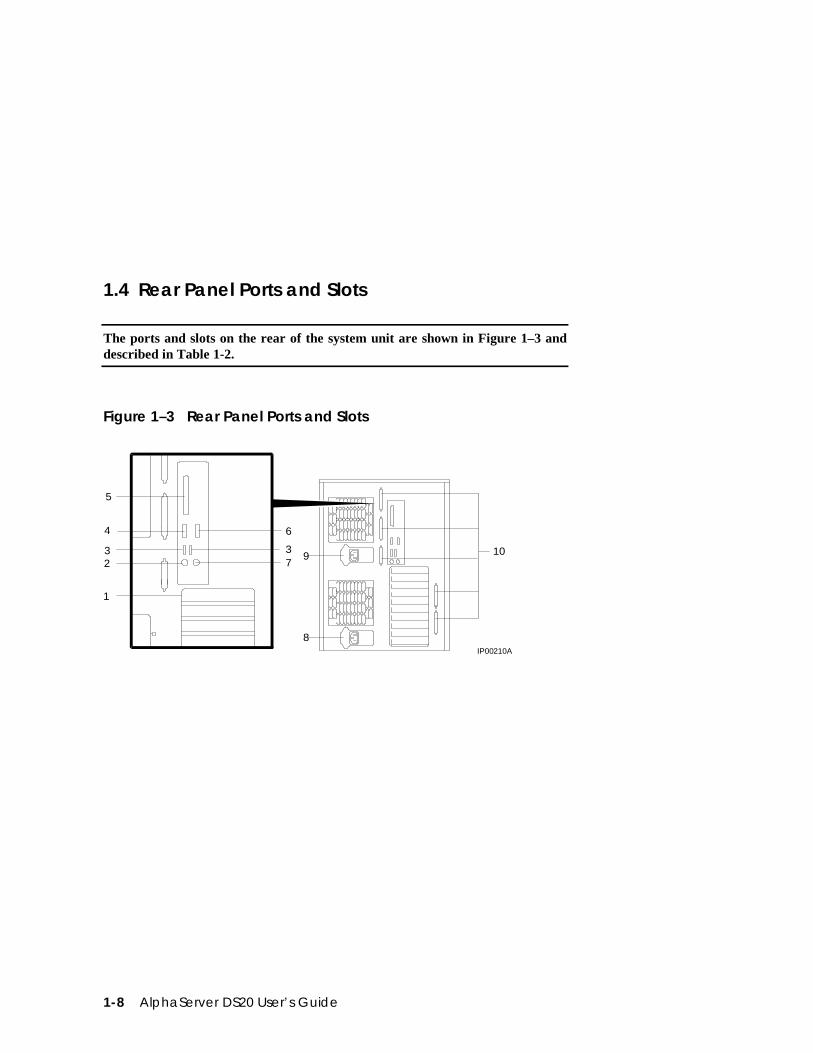
1.4 Rear Panel Ports and Slots
The ports and slots on the rear of the system unit are shown in Figure 1–3 anddescribed in Table 1-2.
Figure 1–3 Rear Panel Ports and Slots
64
5
3 32
1
79
8
10
IP00210A
Overview 1-9
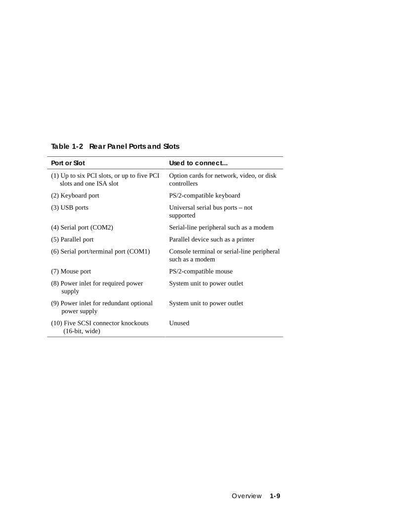
Table 1-2 Rear Panel Ports and Slots
Port or Slot Used to connect...
(1) Up to six PCI slots, or up to five PCIslots and one ISA slot
Option cards for network, video, or diskcontrollers
(2) Keyboard port PS/2-compatible keyboard
(3) USB ports Universal serial bus ports – notsupported
(4) Serial port (COM2) Serial-line peripheral such as a modem
(5) Parallel port Parallel device such as a printer
(6) Serial port/terminal port (COM1) Console terminal or serial-line peripheralsuch as a modem
(7) Mouse port PS/2-compatible mouse
(8) Power inlet for required power supply
System unit to power outlet
(9) Power inlet for redundant optional power supply
System unit to power outlet
(10) Five SCSI connector knockouts (16-bit, wide)
Unused
1-10 AlphaServer DS20 User’s Guide
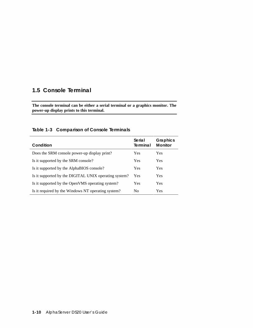
1.5 Console Terminal
The console terminal can be either a serial terminal or a graphics monitor. Thepower-up display prints to this terminal.
Table 1-3 Comparison of Console Terminals
ConditionSerialTerminal
GraphicsMonitor
Does the SRM console power-up display print? Yes Yes
Is it supported by the SRM console? Yes Yes
Is it supported by the AlphaBIOS console? Yes Yes
Is it supported by the DIGITAL UNIX operating system? Yes Yes
Is it supported by the OpenVMS operating system? Yes Yes
Is it required by the Windows NT operating system? No Yes
Overview 1-11
The console terminal can be a serial (character cell) terminal connected to the COM1port or a graphics monitor connected to a VGA adapter on PCI 0. If the consoleterminal is connected to COM1, the entire power-up display prints. (See Section 3.2for information about the power-up display.)
The console environment variable is set to serial when the console terminal is aserial terminal; it is set to graphics when the console terminal is a graphics monitor.(See Section 4.18 for information about environment variables.)
If the console environment variable is set to serial, os_type is set to unix oropenvms, and no terminal is attached to COM1, pressing a carriage return on agraphics terminal attached to the keyboard port (after power-up testing hascompleted) makes it the console device and the console prompt is sent to it.
If the console environment variable is set to graphics and no graphic adapter orkeyboard is present, pressing a carriage return on a serial terminal attached to COM1(after power-up testing has completed) makes it the console device and the consoleprompt is displayed.
NOTE: The console prompt displays only after the entire power-up sequence iscomplete. This can take up to several minutes if the memory is very large.
1-12 AlphaServer DS20 User’s Guide
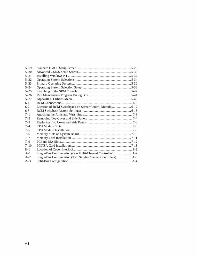
1.6 Options
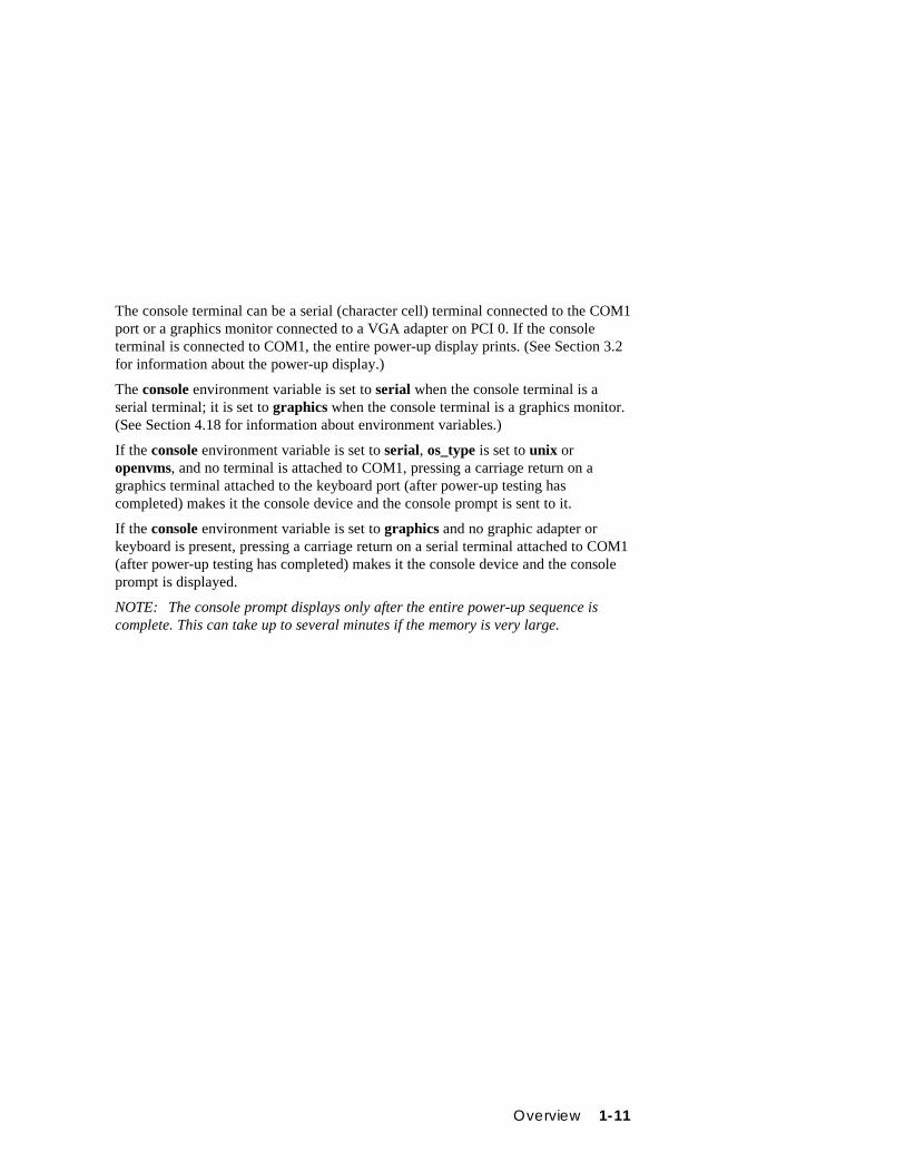
Options include storage, PCI and ISA I/O cards, redundant power, andadditional memory cards. Figure 1–4 shows storage option compartments.
Figure 1–4 Storage Option Compartments
IP00195
Diskette DriveCompartment
CD-ROM DriveCompartment
StorageWorksDrives Shelf
Storage Options
Storage options are located in several compartments inside the system as shown inFigure 1-4. The system accommodates the following types of storage options:
• One diskette drive
• One CD-ROM drive
• Up to seven 3½-inch StorageWorks drives or two 5½-inch drives
Overview 1-13
PCI and ISA Options
The system supports PCI options and ISA options for:
• SCSI storage expansion
• Networking and communications
• Graphics
• Sound
Memory Options
You can increase your system’s memory to 4 gigabytes. More memory allows yoursystem to run memory-intensive software more quickly.
The system supports the following memory option sizes: 128 MB, 256 MB, 512 MB,and 1 GB. Each option is made up of four 200-pin DIMM modules.
Ordering Options
The list of supported options is subject to change. Contact your sales representativefor information on the current list of supported options and for information onordering. If you are an Internet participant, you can obtain information related to theCompaq AlphaServer DS20 system through the DIGITAL FTP archive:
ftp.digital.com: /pub/DEC/Alpha/systems/asds20/docs/
For access through the DIGITAL worldwide web server:
http://www.service.digital.com/alpha/server/ds20.html
Users of the Windows NT operating system can access the Microsoft hardwarecompatibility list (HCL) for a list of officially supported devices:
http://www.windowsnt.digital.com/support/hcl/hcl.htm

Installing the System 2-1
Chapter 2
Installing the System
This chapter explains how to set up and install your system hardware. The followingtopics are discussed:
• System Setup Overview
• Selecting a Location
• Environmental Requirements
• Power Requirements
• Acoustical Data
• System Accessories
• Connecting the System
• Connecting to Network Hardware
• Locking the System
2.1 System Setup OverviewThe following list summarizes the steps for setting up your system. The steps mayvary depending on the options in your system.
1. Select a location for the system, giving consideration to service access,environmental requirements, and power requirements.
2. Confirm that you have all the desired accessories that ship with the system andany accessories you may want to add.
3. Connect the keyboard, mouse, printer, and monitor or terminal.
4. Connect to the network hardware.
5. Verify your hardware setup.
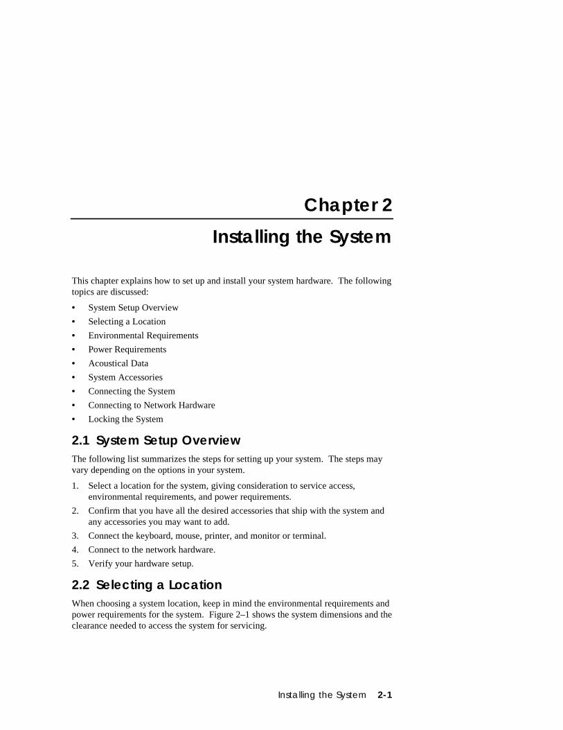
2.2 Selecting a LocationWhen choosing a system location, keep in mind the environmental requirements andpower requirements for the system. Figure 2–1 shows the system dimensions and theclearance needed to access the system for servicing.
2-2 AlphaServer DS20 User’s Guide
Figure 2–1 System Dimensions and Service Area
IP00208
35 cm (14.1 in)
53 cm (21 in)
44 cm (17.4 in)
65 cm (26 in)
1 M (36 in)
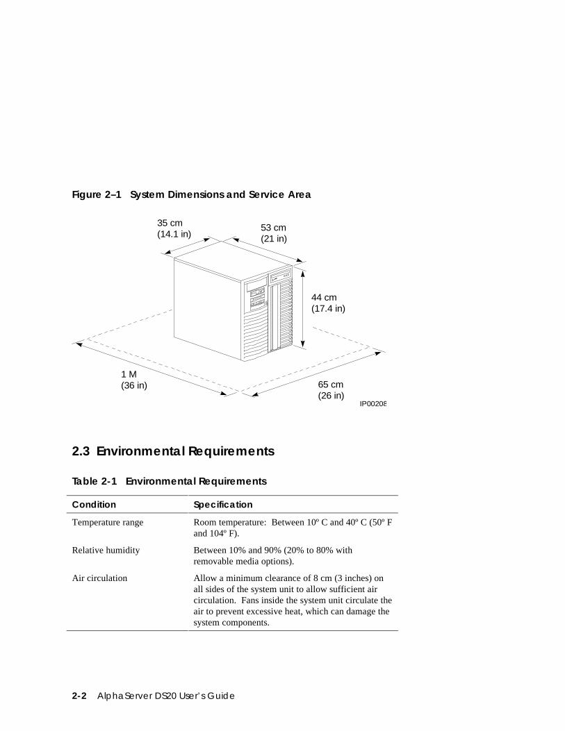
2.3 Environmental Requirements
Table 2-1 Environmental Requirements
Condition Specification
Temperature range Room temperature: Between 10º C and 40º C (50º Fand 104º F).
Relative humidity Between 10% and 90% (20% to 80% withremovable media options).
Air circulation Allow a minimum clearance of 8 cm (3 inches) onall sides of the system unit to allow sufficient aircirculation. Fans inside the system unit circulate theair to prevent excessive heat, which can damage thesystem components.
Installing the System 2-3
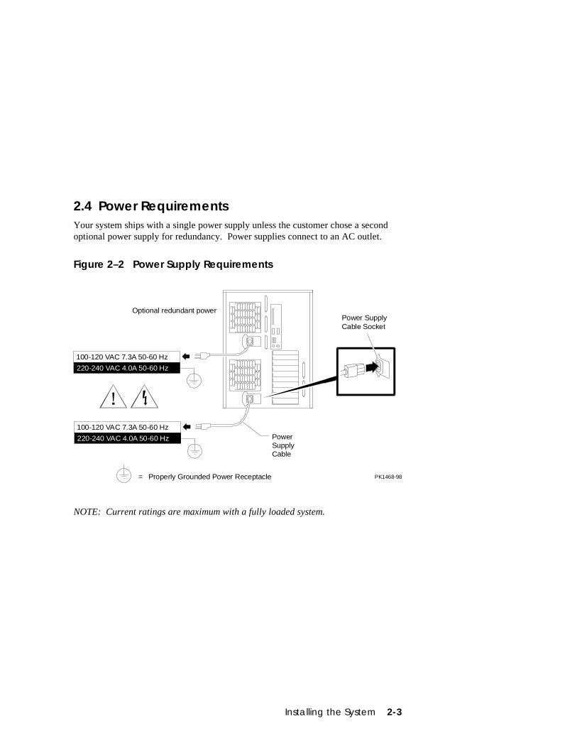
2.4 Power RequirementsYour system ships with a single power supply unless the customer chose a secondoptional power supply for redundancy. Power supplies connect to an AC outlet.
Figure 2–2 Power Supply Requirements
PK1468-98
Power SupplyCable Socket
100-120 VAC 7.3A 50-60 Hz
220-240 VAC 4.0A 50-60 Hz
= Properly Grounded Power Receptacle
PowerSupplyCable
100-120 VAC 7.3A 50-60 Hz
Optional redundant power
220-240 VAC 4.0A 50-60 Hz
NOTE: Current ratings are maximum with a fully loaded system.
2-4 AlphaServer DS20 User’s Guide
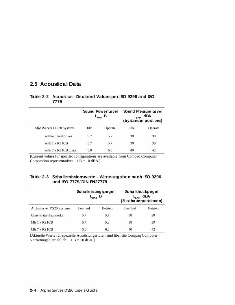
2.5 Acoustical Data
Table 2-2 Acoustics - Declared Values per ISO 9296 and ISO7779
Sound Power LevelLWAd B
Sound Pressure LevelLpAm dBA
(bystander positions)
AlphaServer DS 20 Systems Idle Operate Idle Operate
without hard drives 5.7 5.7 38 38
with 1 x RZ1CB 5.7 5.7 38 39
with 7 x RZ1CB disks 5.8 6.0 40 42
[Current values for specific configurations are available from Compaq ComputerCorporation representatives. 1 B = 10 dBA.]
Table 2-3 Schallemissionswerte - Werteangaben nach ISO 9296und ISO 7779/DIN EN27779
SchalleistungspegelLWAd B
SchalldruckpegelLpAm dBA
(Zuschauerpositionen)
AlphaServer DS20 Systeme Leerlauf Betrieb Leerlauf Betrieb
Ohne Plattenlaufwerke 5,7 5,7 38 38
Mit 1 x RZ1CB 5,7 5,8 38 39
Mit 7 x RZ1CB 5,8 6,0 40 42
[Aktuelle Werte für spezielle Ausrüstungsstufen sind über die Compaq ComputerVertretungen erhältlich. 1 B = 10 dBA.]
Installing the System 2-5
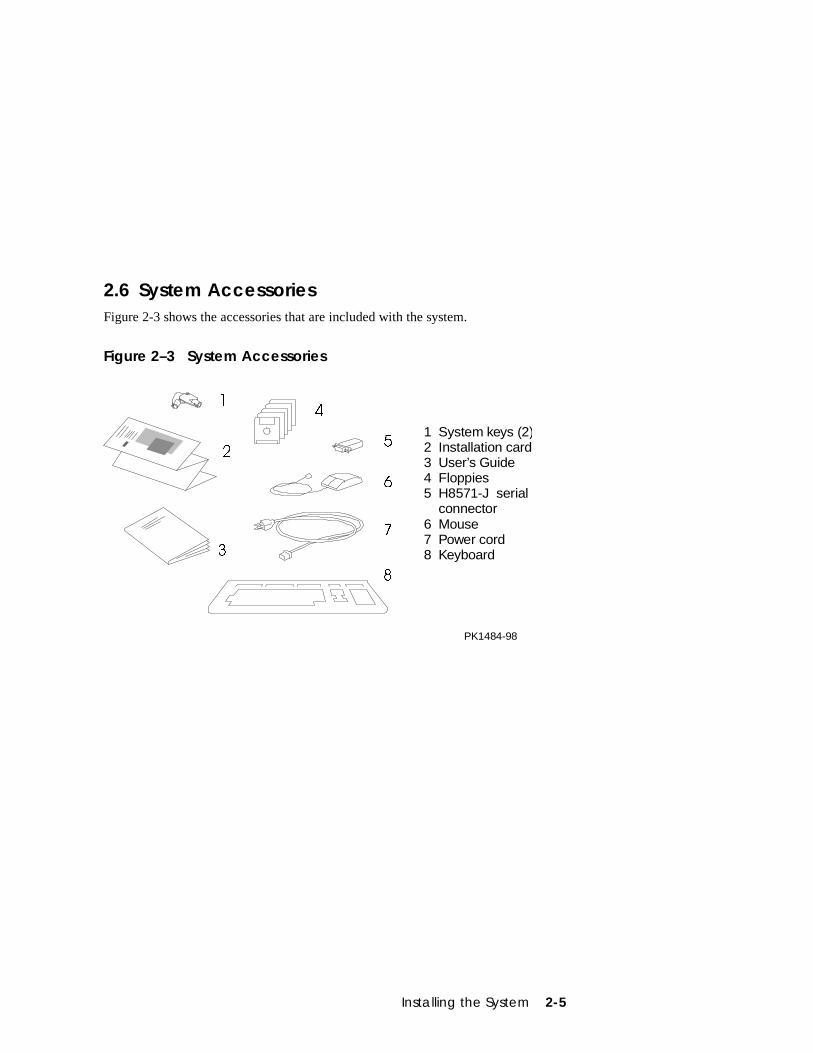
2.6 System AccessoriesFigure 2-3 shows the accessories that are included with the system.
Figure 2–3 System Accessories
�
�
�
�
�
�
�
�
1 System keys (2)2 Installation card3 User’s Guide4 Floppies5 H8571-J serial connector6 Mouse7 Power cord8 Keyboard
PK1484-98
2-6 AlphaServer DS20 User’s Guide
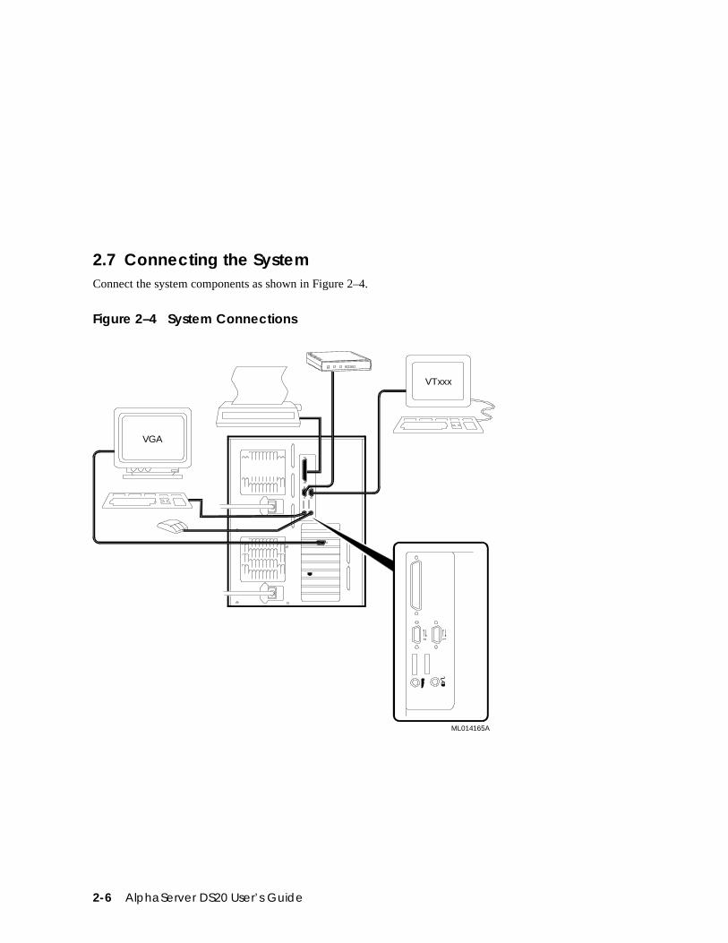
2.7 Connecting the SystemConnect the system components as shown in Figure 2–4.
Figure 2–4 System Connections2 1
VTxxx
VGA
ML014165A
Installing the System 2-7
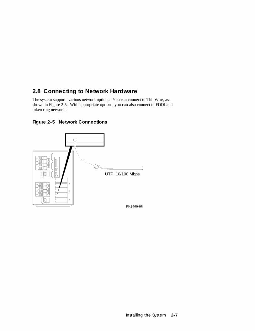
2.8 Connecting to Network HardwareThe system supports various network options. You can connect to ThinWire, asshown in Figure 2-5. With appropriate options, you can also connect to FDDI andtoken ring networks.
Figure 2–5 Network Connections
UTP 10/100 Mbps
PK1469-98
2-8 AlphaServer DS20 User’s Guide
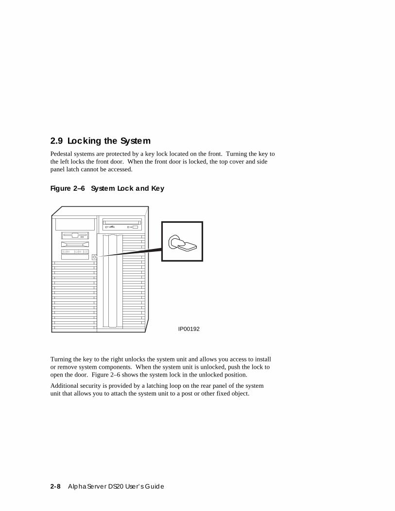
2.9 Locking the SystemPedestal systems are protected by a key lock located on the front. Turning the key tothe left locks the front door. When the front door is locked, the top cover and sidepanel latch cannot be accessed.
Figure 2–6 System Lock and Key
IP00192
Turning the key to the right unlocks the system unit and allows you access to installor remove system components. When the system unit is unlocked, push the lock toopen the door. Figure 2–6 shows the system lock in the unlocked position.
Additional security is provided by a latching loop on the rear panel of the systemunit that allows you to attach the system unit to a post or other fixed object.
Operation 3-1
Chapter 3
Operation
This chapter provides basic operating instructions, including powering up the system,booting, and operating system installation. Note that your choice of operating systemhas already been installed at the factory; this information is provided so that shouldyou decide to change operating systems, you may. It also provides informationabout updating firmware.
Sections in this chapter are:
• Powering Up the System
• Power-Up Display
• Booting DIGITAL UNIX
• Installing DIGITAL UNIX
• Booting OpenVMS
• Installing OpenVMS
• Booting Windows NT
• Installing Windows NT
• Switching Between Operating Systems
• Updating Firmware
• Hard Disk Partitioning
• Using the Halt Button
• Halt Assertion
3-2 AlphaServer DS20 User’s Guide
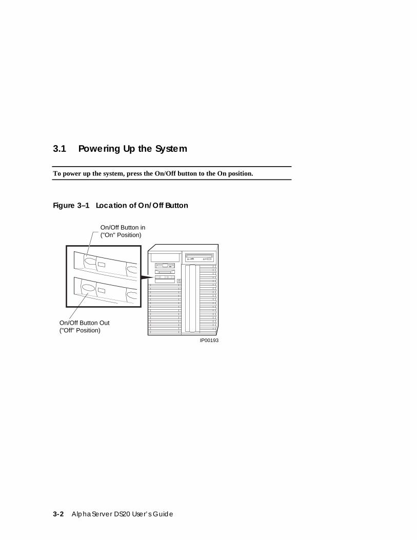
3.1 Powering Up the System
To power up the system, press the On/Off button to the On position.
Figure 3–1 Location of On/Off Button
IP00193
On/Off Button in("On" Position)
On/Off Button Out("Off" Position)
Operation 3-3
Power up the system by pressing in the On/Off button (see Figure 3–1). Testingbegins, and screen text similar to that in Example 3-1 displays (if the consoleterminal is a serial terminal connected to the COM1 port), along with statusmessages in the control panel display. If the console terminal is a graphics monitor,only the last few lines of the power-up display print. See Section 3.2 for moreinformation.
3-4 AlphaServer DS20 User’s Guide
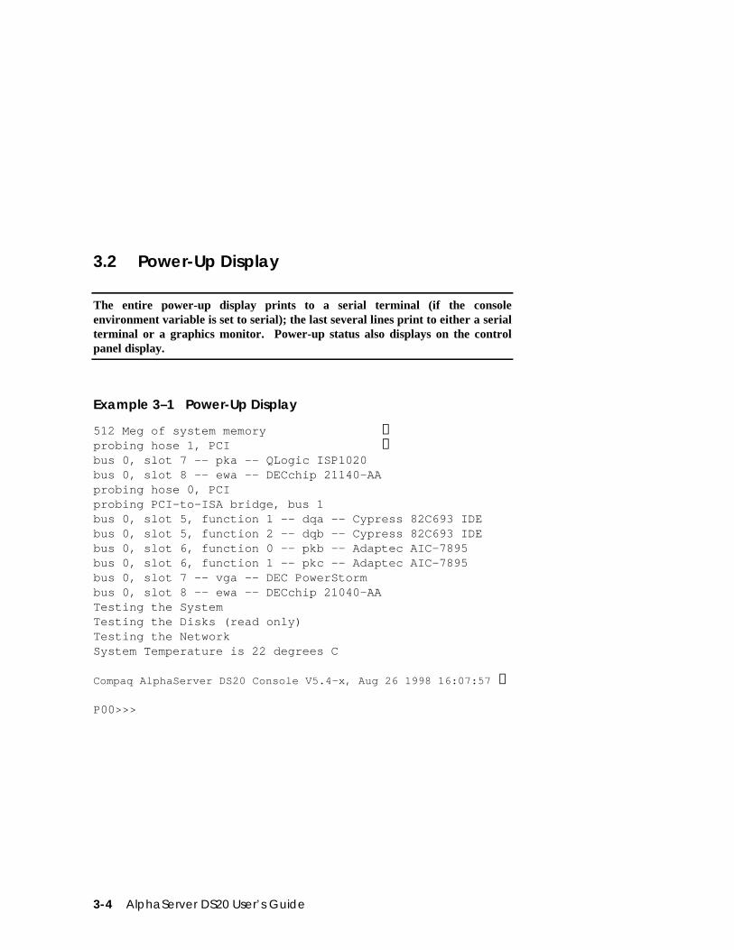
3.2 Power-Up Display
The entire power-up display prints to a serial terminal (if the consoleenvironment variable is set to serial); the last several lines print to either a serialterminal or a graphics monitor. Power-up status also displays on the controlpanel display.
Example 3–1 Power-Up Display
512 Meg of system memory ➊probing hose 1, PCI ➋bus 0, slot 7 -- pka -- QLogic ISP1020bus 0, slot 8 -- ewa -- DECchip 21140-AAprobing hose 0, PCIprobing PCI-to-ISA bridge, bus 1bus 0, slot 5, function 1 -- dqa -- Cypress 82C693 IDEbus 0, slot 5, function 2 -- dqb -- Cypress 82C693 IDEbus 0, slot 6, function 0 -- pkb -- Adaptec AIC-7895bus 0, slot 6, function 1 -- pkc -- Adaptec AIC-7895bus 0, slot 7 -- vga -- DEC PowerStormbus 0, slot 8 -- ewa -- DECchip 21040-AATesting the SystemTesting the Disks (read only)Testing the NetworkSystem Temperature is 22 degrees C
Compaq AlphaServer DS20 Console V5.4-x, Aug 26 1998 16:07:57 ➌
P00>>>
Operation 3-5
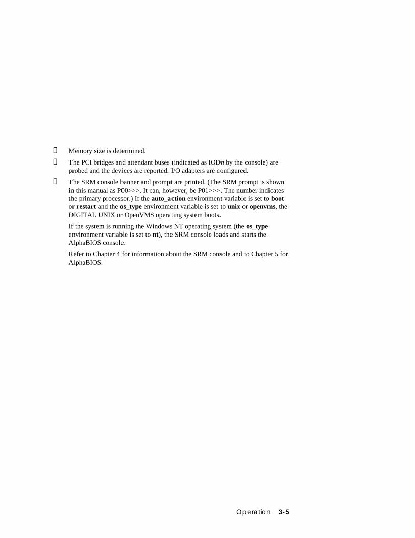
➊ Memory size is determined.
➋ The PCI bridges and attendant buses (indicated as IODn by the console) areprobed and the devices are reported. I/O adapters are configured.
➌ The SRM console banner and prompt are printed. (The SRM prompt is shownin this manual as P00>>>. It can, however, be P01>>>. The number indicatesthe primary processor.) If the auto_action environment variable is set to bootor restart and the os_type environment variable is set to unix or openvms, theDIGITAL UNIX or OpenVMS operating system boots.
If the system is running the Windows NT operating system (the os_typeenvironment variable is set to nt), the SRM console loads and starts theAlphaBIOS console.
Refer to Chapter 4 for information about the SRM console and to Chapter 5 forAlphaBIOS.
3-6 AlphaServer DS20 User’s Guide
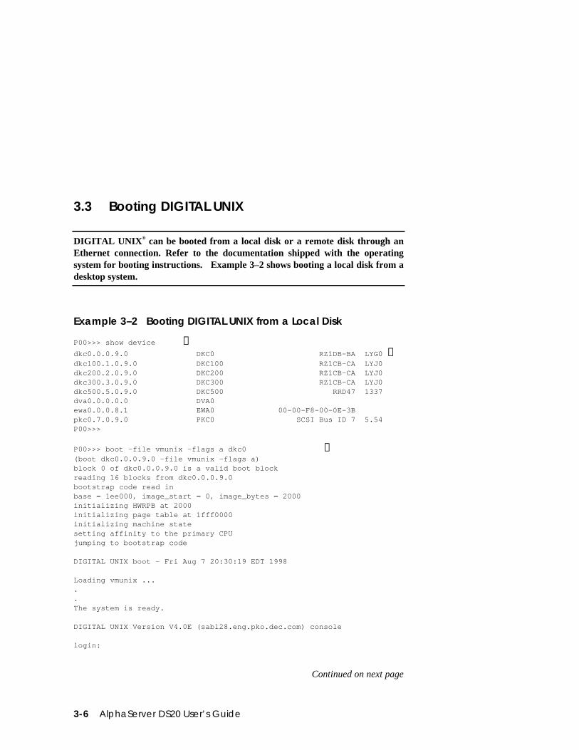
3.3 Booting DIGITAL UNIX
DIGITAL UNIX® can be booted from a local disk or a remote disk through anEthernet connection. Refer to the documentation shipped with the operatingsystem for booting instructions. Example 3–2 shows booting a local disk from adesktop system.
Example 3–2 Booting DIGITAL UNIX from a Local Disk
P00>>> show device ➊dkc0.0.0.9.0 DKC0 RZ1DB-BA LYG0 ➋dkc100.1.0.9.0 DKC100 RZ1CB-CA LYJ0dkc200.2.0.9.0 DKC200 RZ1CB-CA LYJ0dkc300.3.0.9.0 DKC300 RZ1CB-CA LYJ0dkc500.5.0.9.0 DKC500 RRD47 1337dva0.0.0.0.0 DVA0ewa0.0.0.8.1 EWA0 00-00-F8-00-0E-3Bpkc0.7.0.9.0 PKC0 SCSI Bus ID 7 5.54P00>>>
P00>>> boot -file vmunix -flags a dkc0 ➌(boot dkc0.0.0.9.0 -file vmunix -flags a)block 0 of dkc0.0.0.9.0 is a valid boot blockreading 16 blocks from dkc0.0.0.9.0bootstrap code read inbase = 1ee000, image_start = 0, image_bytes = 2000initializing HWRPB at 2000initializing page table at 1fff0000initializing machine statesetting affinity to the primary CPUjumping to bootstrap code
DIGITAL UNIX boot - Fri Aug 7 20:30:19 EDT 1998
Loading vmunix .....The system is ready.
DIGITAL UNIX Version V4.0E (sabl28.eng.pko.dec.com) console
login:
Continued on next page
Operation 3-7
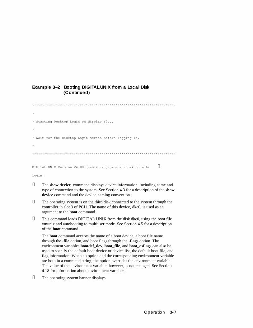
Example 3–2 Booting DIGITAL UNIX from a Local Disk(Continued)
************************************************************************
*
* Starting Desktop Login on display :0...
*
* Wait for the Desktop Login screen before logging in.
*
************************************************************************
DIGITAL UNIX Version V4.0E (sabl28.eng.pko.dec.com) console ➍
login:
➊ The show device command displays device information, including name andtype of connection to the system. See Section 4.3 for a description of the showdevice command and the device naming convention.
➋ The operating system is on the third disk connected to the system through thecontroller in slot 3 of PCI1. The name of this device, dkc0, is used as anargument to the boot command.
➌ This command loads DIGITAL UNIX from the disk dkc0, using the boot filevmunix and autobooting to multiuser mode. See Section 4.5 for a descriptionof the boot command.
The boot command accepts the name of a boot device, a boot file namethrough the -file option, and boot flags through the -flags option. Theenvironment variables bootdef_dev, boot_file, and boot_osflags can also beused to specify the default boot device or device list, the default boot file, andflag information. When an option and the corresponding environment variableare both in a command string, the option overrides the environment variable.The value of the environment variable, however, is not changed. See Section4.18 for information about environment variables.
➍ The operating system banner displays.
3-8 AlphaServer DS20 User’s Guide
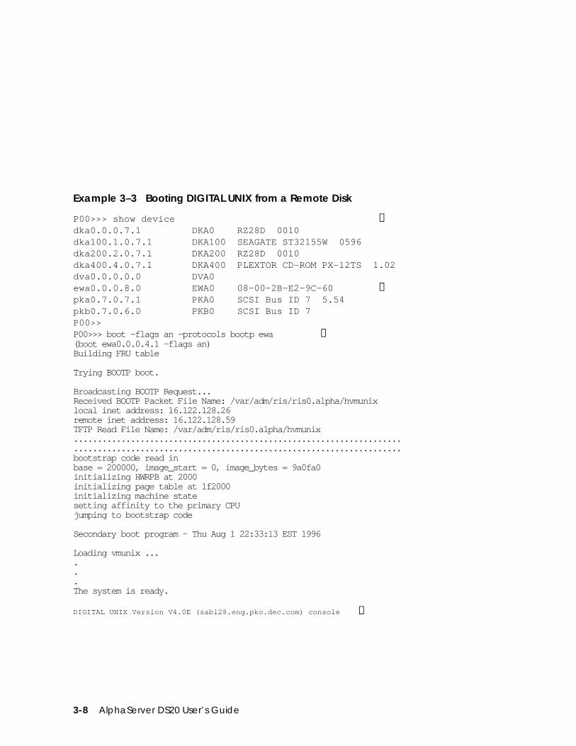
Example 3–3 Booting DIGITAL UNIX from a Remote Disk
P00>>> show device ➊dka0.0.0.7.1 DKA0 RZ28D 0010dka100.1.0.7.1 DKA100 SEAGATE ST32155W 0596dka200.2.0.7.1 DKA200 RZ28D 0010dka400.4.0.7.1 DKA400 PLEXTOR CD-ROM PX-12TS 1.02dva0.0.0.0.0 DVA0ewa0.0.0.8.0 EWA0 08-00-2B-E2-9C-60 ➋pka0.7.0.7.1 PKA0 SCSI Bus ID 7 5.54pkb0.7.0.6.0 PKB0 SCSI Bus ID 7P00>>P00>>> boot -flags an -protocols bootp ewa ➌(boot ewa0.0.0.4.1 -flags an)Building FRU table
Trying BOOTP boot.
Broadcasting BOOTP Request...Received BOOTP Packet File Name: /var/adm/ris/ris0.alpha/hvmunixlocal inet address: 16.122.128.26remote inet address: 16.122.128.59TFTP Read File Name: /var/adm/ris/ris0.alpha/hvmunix..........................................................................................................................................bootstrap code read inbase = 200000, image_start = 0, image_bytes = 9a0fa0initializing HWRPB at 2000initializing page table at 1f2000initializing machine statesetting affinity to the primary CPUjumping to bootstrap code
Secondary boot program - Thu Aug 1 22:33:13 EST 1996
Loading vmunix ......The system is ready.
DIGITAL UNIX Version V4.0E (sabl28.eng.pko.dec.com) console ➍
Operation 3-9
➊ The show device command displays device information, including name andtype of connection to the system. See Section 4.3 for a description of the showdevice command and the device naming convention.
➋ The operating system is on a remote disk accessed through the Ethernetcontroller in slot 4 of PCI1. The name of this device, ewa0, is used as anargument to the boot command.
➌ This command loads DIGITAL UNIX from ewa0, autobooting to multiusermode. See Section 4.5 for a description of the boot command.
The boot command accepts the name of a boot device, a boot file namethrough the -file option, and boot flags through the -flags option. Theenvironment variables bootdef_dev, boot_file, and boot_osflags can also beused to specify the default boot device or device list, the default boot file, andflag information. When an option and the corresponding environment variableare both in a command string, the option overrides the environment variable.The value of the environment variable, however, is not changed. See Section4.18 for information about environment variables.
➍ The operating system banner displays.
3-10 AlphaServer DS20 User’s Guide
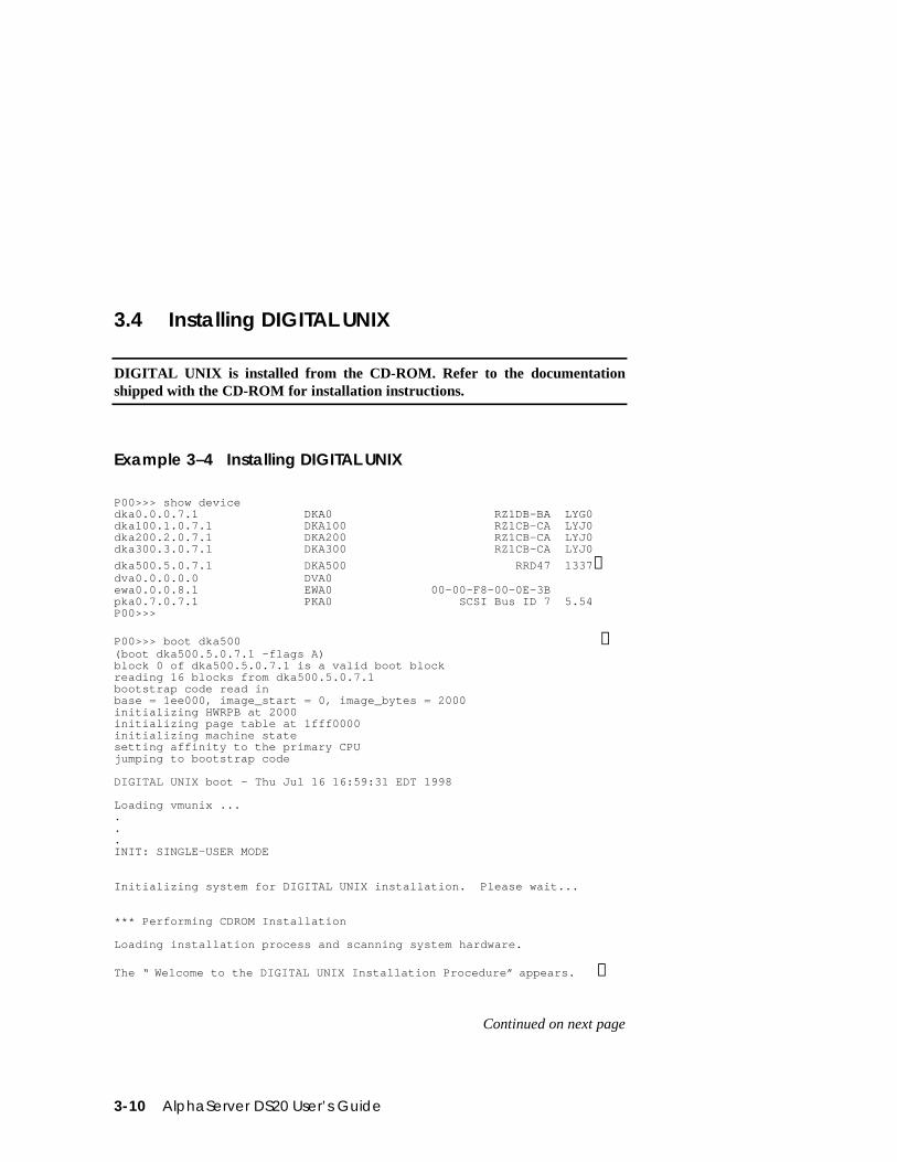
3.4 Installing DIGITAL UNIX
DIGITAL UNIX is installed from the CD-ROM. Refer to the documentationshipped with the CD-ROM for installation instructions.
Example 3–4 Installing DIGITAL UNIX
P00>>> show devicedka0.0.0.7.1 DKA0 RZ1DB-BA LYG0dka100.1.0.7.1 DKA100 RZ1CB-CA LYJ0dka200.2.0.7.1 DKA200 RZ1CB-CA LYJ0dka300.3.0.7.1 DKA300 RZ1CB-CA LYJ0
dka500.5.0.7.1 DKA500 RRD47 1337➊dva0.0.0.0.0 DVA0ewa0.0.0.8.1 EWA0 00-00-F8-00-0E-3Bpka0.7.0.7.1 PKA0 SCSI Bus ID 7 5.54P00>>>
P00>>> boot dka500 ➊(boot dka500.5.0.7.1 -flags A)block 0 of dka500.5.0.7.1 is a valid boot blockreading 16 blocks from dka500.5.0.7.1bootstrap code read inbase = 1ee000, image_start = 0, image_bytes = 2000initializing HWRPB at 2000initializing page table at 1fff0000initializing machine statesetting affinity to the primary CPUjumping to bootstrap code
DIGITAL UNIX boot - Thu Jul 16 16:59:31 EDT 1998
Loading vmunix ......INIT: SINGLE-USER MODE
Initializing system for DIGITAL UNIX installation. Please wait...
*** Performing CDROM Installation
Loading installation process and scanning system hardware.
The “ Welcome to the DIGITAL UNIX Installation Procedure” appears. ➋
Continued on next page
Operation 3-11
➊ Use the boot command to install the operating system from the CD-ROM,which is always dka500.
➋ See your operating system documentation for further installation instructions.
3-12 AlphaServer DS20 User’s Guide
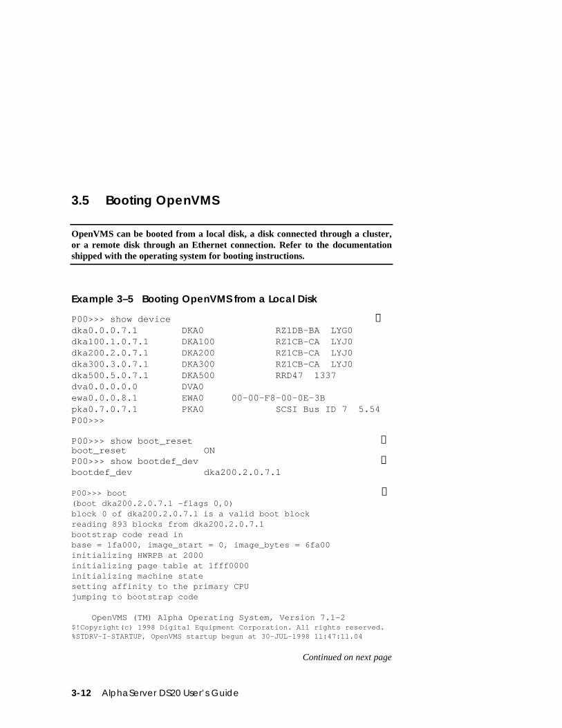
3.5 Booting OpenVMS
OpenVMS can be booted from a local disk, a disk connected through a cluster,or a remote disk through an Ethernet connection. Refer to the documentationshipped with the operating system for booting instructions.
Example 3–5 Booting OpenVMS from a Local Disk
P00>>> show device ➊dka0.0.0.7.1 DKA0 RZ1DB-BA LYG0dka100.1.0.7.1 DKA100 RZ1CB-CA LYJ0dka200.2.0.7.1 DKA200 RZ1CB-CA LYJ0dka300.3.0.7.1 DKA300 RZ1CB-CA LYJ0dka500.5.0.7.1 DKA500 RRD47 1337dva0.0.0.0.0 DVA0ewa0.0.0.8.1 EWA0 00-00-F8-00-0E-3Bpka0.7.0.7.1 PKA0 SCSI Bus ID 7 5.54P00>>>
P00>>> show boot_reset ➋boot_reset ONP00>>> show bootdef_dev ➌bootdef_dev dka200.2.0.7.1
P00>>> boot ➍(boot dka200.2.0.7.1 -flags 0,0)block 0 of dka200.2.0.7.1 is a valid boot blockreading 893 blocks from dka200.2.0.7.1bootstrap code read inbase = 1fa000, image_start = 0, image_bytes = 6fa00initializing HWRPB at 2000initializing page table at 1fff0000initializing machine statesetting affinity to the primary CPUjumping to bootstrap code
OpenVMS (TM) Alpha Operating System, Version 7.1-2$!Copyright(c) 1998 Digital Equipment Corporation. All rights reserved.%STDRV-I-STARTUP, OpenVMS startup begun at 30-JUL-1998 11:47:11.04
Continued on next page
Operation 3-13
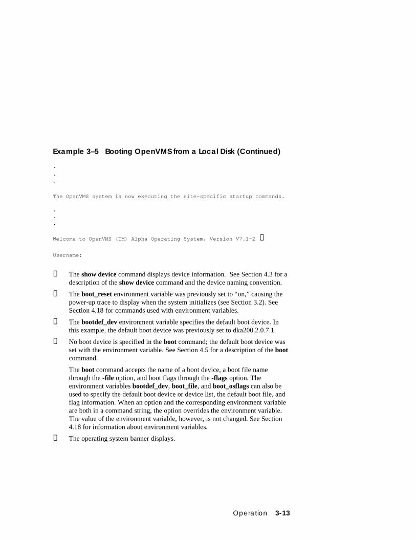
Example 3–5 Booting OpenVMS from a Local Disk (Continued)
.
.
.
The OpenVMS system is now executing the site-specific startup commands.
.
.
.
Welcome to OpenVMS (TM) Alpha Operating System, Version V7.1-2 ➎
Username:
➊ The show device command displays device information. See Section 4.3 for adescription of the show device command and the device naming convention.
➋ The boot_reset environment variable was previously set to “on,” causing thepower-up trace to display when the system initializes (see Section 3.2). SeeSection 4.18 for commands used with environment variables.
➌ The bootdef_dev environment variable specifies the default boot device. Inthis example, the default boot device was previously set to dka200.2.0.7.1.
➍ No boot device is specified in the boot command; the default boot device wasset with the environment variable. See Section 4.5 for a description of the bootcommand.
The boot command accepts the name of a boot device, a boot file namethrough the -file option, and boot flags through the -flags option. Theenvironment variables bootdef_dev, boot_file, and boot_osflags can also beused to specify the default boot device or device list, the default boot file, andflag information. When an option and the corresponding environment variableare both in a command string, the option overrides the environment variable.The value of the environment variable, however, is not changed. See Section4.18 for information about environment variables.
➎ The operating system banner displays.
3-14 AlphaServer DS20 User’s Guide
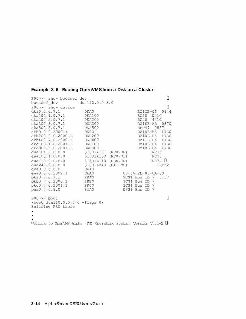
Example 3–6 Booting OpenVMS from a Disk on a Cluster
P00>>> show bootdef_dev ➊bootdef_dev dua110.0.0.8.0P00>>> show device ➋dka0.0.0.7.1 DKA0 RZ1CB-CS 0844dka100.1.0.7.1 DKA100 RZ28 D41Cdka200.2.0.7.1 DKA200 RZ28 441Cdka300.3.0.7.1 DKA300 RZ1EF-AB 0370dka500.5.0.7.1 DKA500 RRD47 0557dkb0.0.0.2000.1 DKB0 RZ1DB-BA LYG0dkb200.2.0.2000.1 DKB200 RZ1DB-BA LYG0dkb400.4.0.2000.1 DKB400 RZ1CB-BA LYG0dkc100.1.0.2001.1 DKC100 RZ1DB-BA LYG0dkc300.3.0.2001.1 DKC300 RZ1DB-BA LYG0dua101.3.0.8.0 $1$DIA101 (RF0700) RF35dua103.1.0.8.0 $1$DIA103 (RF0701) RF36dua110.0.0.8.0 $1$DIA110 (DENVER) RF74 ➌dua240.2.0.8.0 $1$DIA240 (E1ILMO) EF52dva0.0.0.0.0 DVA0ewa0.0.0.2002.1 EWA0 00-06-2B-00-0A-59pka0.7.0.7.1 PKA0 SCSI Bus ID 7 5.57pkb0.7.0.2000.1 PKB0 SCSI Bus ID 7pkc0.7.0.2001.1 PKC0 SCSI Bus ID 7pua0.7.0.8.0 PIA0 DSSI Bus ID 7
P00>>> boot ➍(boot dua110.0.0.8.0 -flags 0)Building FRU table...Welcome to OpenVMS Alpha (TM) Operating System, Version V7.1-2 ➎
Operation 3-15
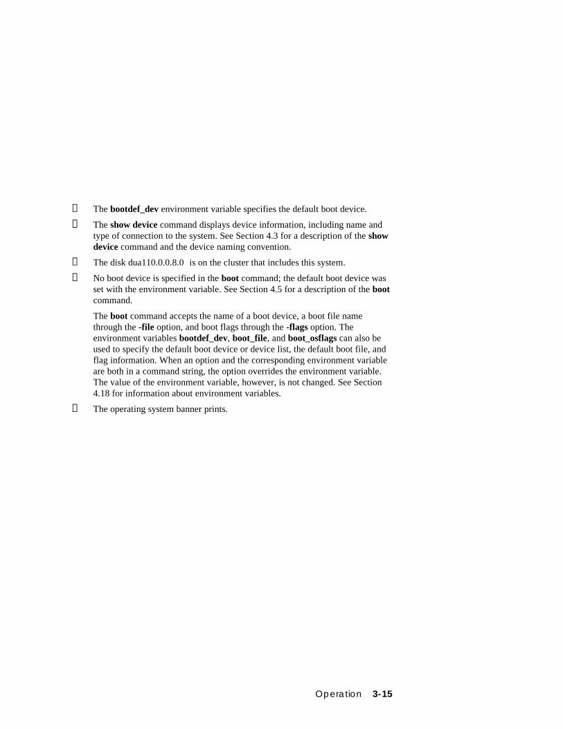
➊ The bootdef_dev environment variable specifies the default boot device.
➋ The show device command displays device information, including name andtype of connection to the system. See Section 4.3 for a description of the showdevice command and the device naming convention.
➌ The disk dua110.0.0.8.0 is on the cluster that includes this system.
➍ No boot device is specified in the boot command; the default boot device wasset with the environment variable. See Section 4.5 for a description of the bootcommand.
The boot command accepts the name of a boot device, a boot file namethrough the -file option, and boot flags through the -flags option. Theenvironment variables bootdef_dev, boot_file, and boot_osflags can also beused to specify the default boot device or device list, the default boot file, andflag information. When an option and the corresponding environment variableare both in a command string, the option overrides the environment variable.The value of the environment variable, however, is not changed. See Section4.18 for information about environment variables.
➎ The operating system banner prints.
3-16 AlphaServer DS20 User’s Guide
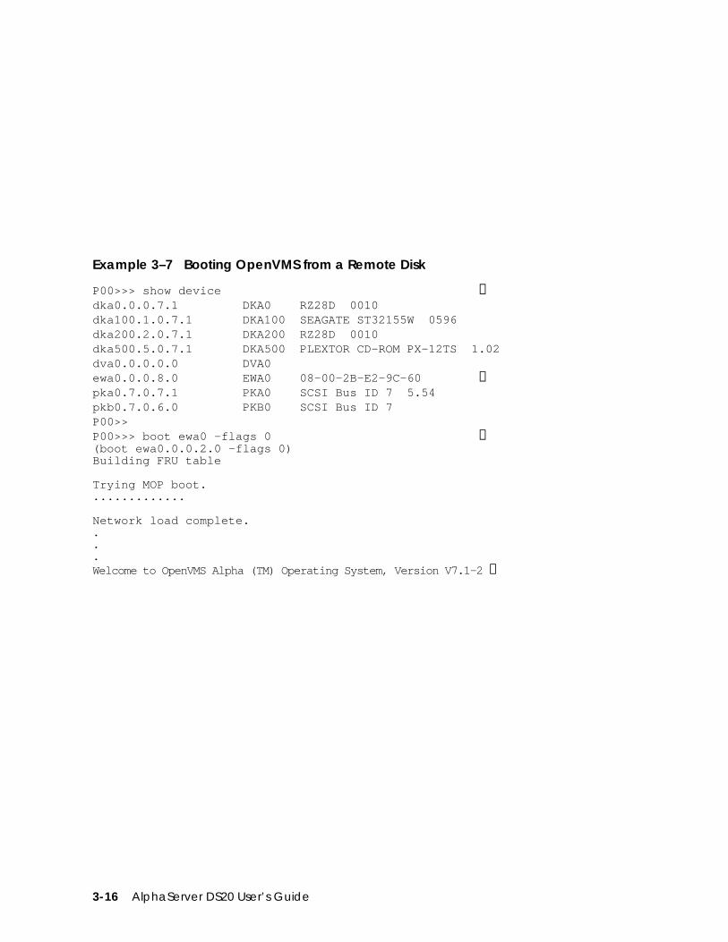
Example 3–7 Booting OpenVMS from a Remote Disk
P00>>> show device ➊dka0.0.0.7.1 DKA0 RZ28D 0010dka100.1.0.7.1 DKA100 SEAGATE ST32155W 0596dka200.2.0.7.1 DKA200 RZ28D 0010dka500.5.0.7.1 DKA500 PLEXTOR CD-ROM PX-12TS 1.02dva0.0.0.0.0 DVA0ewa0.0.0.8.0 EWA0 08-00-2B-E2-9C-60 ➊pka0.7.0.7.1 PKA0 SCSI Bus ID 7 5.54pkb0.7.0.6.0 PKB0 SCSI Bus ID 7P00>>P00>>> boot ewa0 -flags 0 ➋(boot ewa0.0.0.2.0 -flags 0)Building FRU table
Trying MOP boot..............
Network load complete....Welcome to OpenVMS Alpha (TM) Operating System, Version V7.1-2 ➌
Operation 3-17
➊ The show device command displays device information, including name andtype of connection to the system. In this example the Ethernet connection isewa0. See Section 4.3 for a description of the show device command and thedevice naming convention.
➋ The boot command specifies ewa0 as the boot device. See Section 4.5 for adescription of the boot command.
The boot command accepts the name of a boot device, a boot file namethrough the -file option, and boot flags through the -flags option. Theenvironment variables bootdef_dev, boot_file, and boot_osflags can also beused to specify the default boot device or device list, the default boot file, andflag information. When an option and the corresponding environment variableare both in a command string, the option overrides the environment variable.The value of the environment variable, however, is not changed. See Section4.18 for information about environment variables.
➌ The operating system banner prints.
3-18 AlphaServer DS20 User’s Guide
3.6 Installing OpenVMS
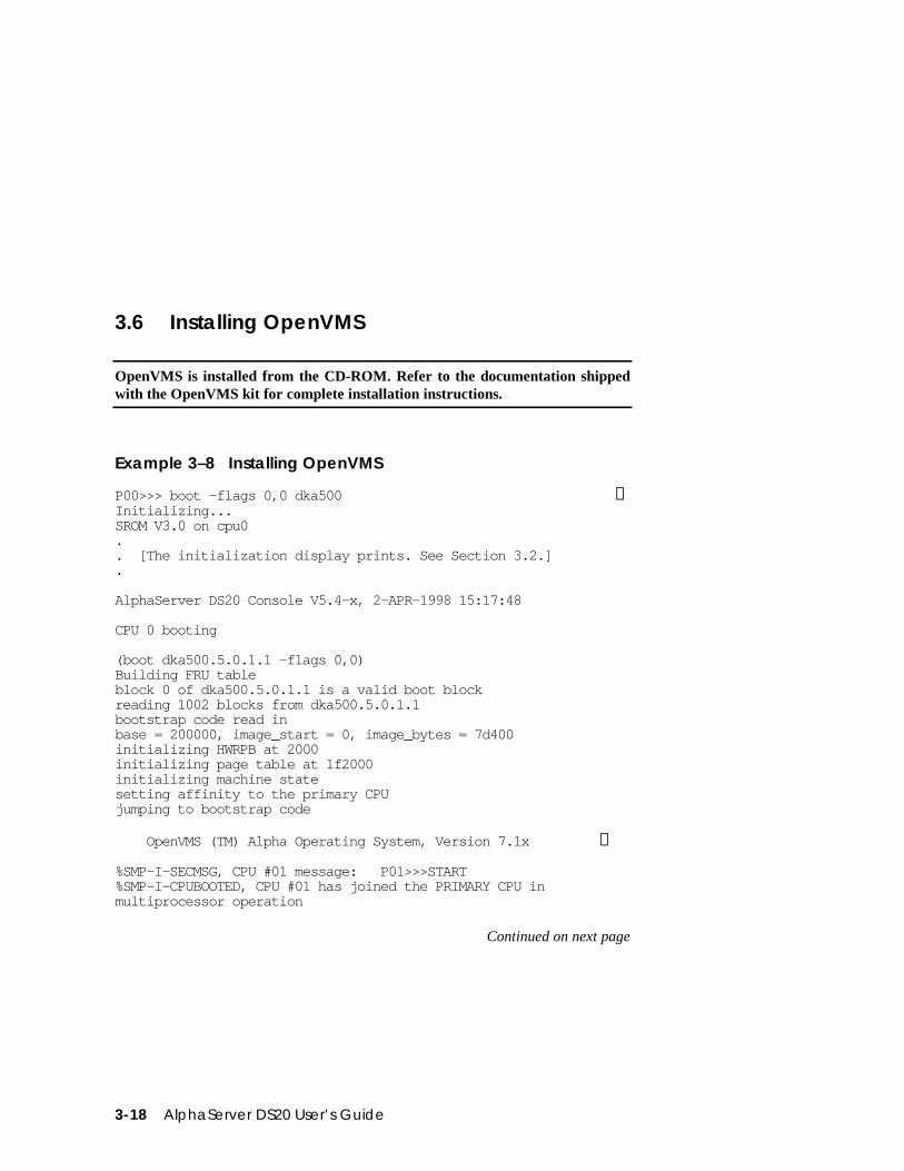
OpenVMS is installed from the CD-ROM. Refer to the documentation shippedwith the OpenVMS kit for complete installation instructions.
Example 3–8 Installing OpenVMS
P00>>> boot -flags 0,0 dka500 ➊Initializing...SROM V3.0 on cpu0.. [The initialization display prints. See Section 3.2.].
AlphaServer DS20 Console V5.4-x, 2-APR-1998 15:17:48
CPU 0 booting
(boot dka500.5.0.1.1 -flags 0,0)Building FRU tableblock 0 of dka500.5.0.1.1 is a valid boot blockreading 1002 blocks from dka500.5.0.1.1bootstrap code read inbase = 200000, image_start = 0, image_bytes = 7d400initializing HWRPB at 2000initializing page table at 1f2000initializing machine statesetting affinity to the primary CPUjumping to bootstrap code
OpenVMS (TM) Alpha Operating System, Version 7.1x ➋
%SMP-I-SECMSG, CPU #01 message: P01>>>START%SMP-I-CPUBOOTED, CPU #01 has joined the PRIMARY CPU inmultiprocessor operation
Continued on next page
Operation 3-19
Example 3–8 Installing OpenVMS (Continued)
Installing required known files...
Configuring devices...
****************************************************************
You can install or upgrade the OpenVMS Alpha operating system or you can install or upgrade layered products that are included on the OpenVMS Alpha operating system CD-ROM.
You can also execute DCL commands and procedures to perform "standalone" tasks, such as backing up the system disk.
Please choose one of the following:
1) Install or upgrade OpenVMS Alpha Version 7.1x 2) List layered product kits that this procedure can install 3) Install or upgrade layered product(s) 4) Execute DCL commands and procedures 5) Shut down this system
Enter CHOICE or ? to repeat menu: (1/2/3/4/5/?)
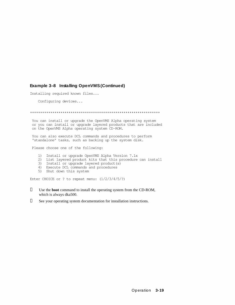
➊ Use the boot command to install the operating system from the CD-ROM,which is always dka500.
➋ See your operating system documentation for installation instructions.
3-20 AlphaServer DS20 User’s Guide
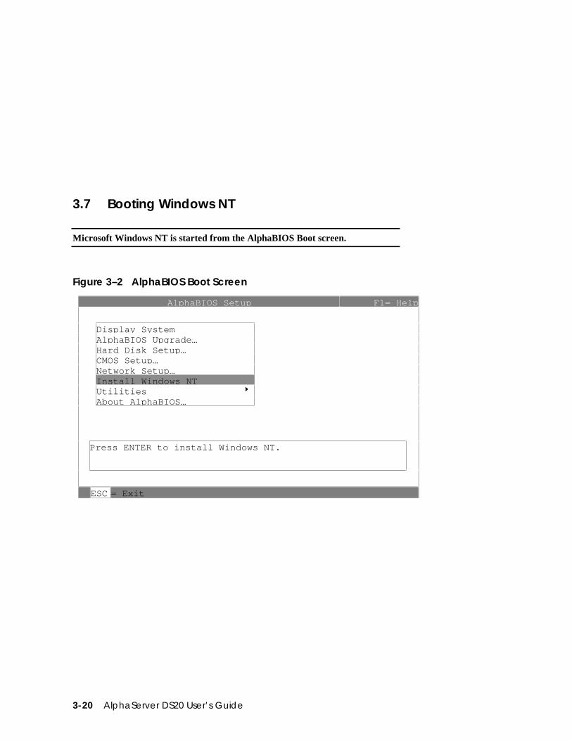
3.7 Booting Windows NT
Microsoft Windows NT is started from the AlphaBIOS Boot screen.
Figure 3–2 AlphaBIOS Boot Screen
AlphaBIOS Setup F1= Help
Display SystemAl phaBIOS U pgrade…Hard Disk Setu p…CMOS Setup…Network Setu p…Install Windows NTUtilities 8About Al phaBIOS…
Press ENTER to install Windows NT.
ESC = Exit
Operation 3-21
Two SRM environment variables must be set properly for Windows NT to boot. Thesetting of the SRM os_type environment variable determines if AlphaBIOS is loadedand started on reset and power-up. If os_type is set to nt, after the power-up displaythe SRM console is loaded and started, and it then loads and starts the AlphaBIOSconsole. AlphaBIOS must be running before Windows NT can be booted. WindowsNT requires a graphics monitor as its console. Setting the SRM console environmentvariable to graphics and having a graphics monitor attached to your system meetsthis requirement. After setting these two variables, you have to power-down andpower-up your system for them to take effect.
The method used for booting Windows NT is determined by the setting of AutoStart in the AlphaBIOS Standard CMOS Setup screen (see Chapter 5).
• If Auto Start is enabled, the primary version of Windows NT startsautomatically.
• If Auto Start is disabled, use the arrow keys to select the Windows NT versionto start. Press Enter to boot Windows NT.
NOTE: The SRM console environment variable must be set to graphics beforebooting Windows NT, though this setting is not necessary to run AlphaBIOS.
3-22 AlphaServer DS20 User’s Guide
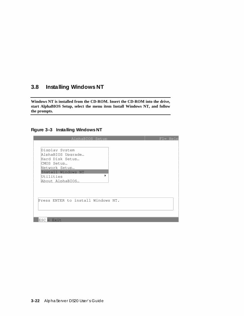
3.8 Installing Windows NT
Windows NT is installed from the CD-ROM. Insert the CD-ROM into the drive,start AlphaBIOS Setup, select the menu item Install Windows NT, and followthe prompts.
Figure 3–3 Installing Windows NT
AlphaBIOS Setup F1= Help
Display SystemAl phaBIOS U pgrade…Hard Disk Setu p…CMOS Setup…Network Setu p…Install Windows NTUtilities 8About Al phaBIOS…
Press ENTER to install Windows NT.
ESC = Exit
Operation 3-23
Windows NT requires a partitioned and formatted hard disk drive. If your drive isnot partitioned or formatted, follow the instructions in Section 3.10 before installingthe Windows NT operating system.
Up to three versions of Windows NT can be resident in a system at one time.
If this is a new Windows NT installation, start with this procedure:
1. Use CMOS Setup to set the system date and time: start AlphaBIOS Setup,select CMOS Setup, and press Enter.
2. Perform an express hard disk setup: return to the main AlphaBIOS Setupscreen, select Hard Disk Setup, and press Enter.
3. Perform an express hard disk setup by pressing F7 to enter Express Setup.
4. Continue the setup by pressing the F10 key.
5. Go to the procedure below.
This procedure is for all Windows NT installations:
Read these instructions carefully paying particular attention to step 5.
1. Put the Windows NT CD into the CD-ROM drive.
2. Start AlphaBIOS Setup, select Install Windows NT, and press Enter.
3. Windows NT 4.0 Setup incorrectly believes that it recognizes and supports theunused onboard AIC-7895 SCSI controller and will load its driver unless it isprevented from doing so. Your system’s CD-ROM is connected to a SCSIcontroller on the PCI bus and its driver must be loaded. To prevent the loadingof the WRONG driver quickly press F6 when the Windows NT banner displays(blue screen). If Windows NT autodetects the AIC-78xx and F6 was not pressedat the right time, start over again. For further information, see the Windows NT4.0 readme.txt file.
4. To select the appropriate driver:
a. Insert the AlphaServer DS20 Windows NT floppy into the floppy drive.
b. If step 3 was successful, Windows NT Setup will announce that it cannotdetermine the type of one or more mass storage controllers, press ’S’ tospecify an additional controller.
c. From the list, choose “Other.” The floppy’s list will appear.
d. Choose the “Adaptec AIC-78xx PCI SCSI Controller (NT4.0).”
Follow the prompts to complete the installation. For more information on installingWindows NT, refer to the Installation Guide in your Windows NT software package.
3-24 AlphaServer DS20 User’s Guide
3.9 Switching Between Operating Systems
The system supports the use of multiple operating systems on different systemand data disks not in the machine at the same time; that is you can have a set of disks for each operating system.
CAUTION: This operation is not for the faint hearted especially if you have ashadow system disk and shadow arrays. The file structures of the threeoperating systems are incompatible. Therefore all disks used by oneoperating system must be removed when another is put in its place.Upon reinstallation all disks must be placed in the same physicallocations. It is therefore necessary to keep track of the location of eachdisk in the system.
3.9.1 Switching to Windows NTUse the following procedure.
1. Shut down the operating system and power off the system.
2. Remove and mark the physical location of each disk in the system.
3. Either place blank disks or your Windows NT disk set into the system. (If youare placing a Windows NT disk set into the system, be sure that each disk isreplaced in the same physical location from which it was removed.)
4. Power on the system.
5. Enter the following commands at the SRM console prompt:
P00>>> set os_type ntP00>>> init
6. Either install Windows NT, see Section 3.8, or at the AlphaBIOS boot screen,start AlphaBIOS setup (F2), select CMOS Setup, and press Enter.
7. Set the system date and time.
8. In CMOS Setup, check that the setup for the floppy and other basic parametersare accurate. Set system-specific parameters, such as the memory test andpassword, in Advanced CMOS Setup as needed. Press F10 to save the changes.
9. From the AlphaBIOS Setup screen select Utilities. In the selection box, chooseOS Selection Setup. Make sure the selections (boot name, boot file, and so on)are what you want. Press F10 to save the changes.
10. Return to the boot screen and boot Windows NT.
Operation 3-25
3.9.2 Switching to DIGITAL UNIX or OpenVMSUse the following procedure.
1. Shut down the operating system and power off the system.
2. Remove and mark the physical location of each disk in the system.
3. Either place blank disks or your DIGITAL UNIX or OpenVMS disk set into thesystem. No matter which disk set you are placing into the system, be surethat each disk is placed in the same physical location from which it wasremoved.
4. Power on the system.
5. In AlphaBIOS, access the Advanced CMOS Setup screen and change theConsole Selection to DIGITAL UNIX (SRM) or OpenVMS (SRM) asappropriate. Press F10 to save the change. This menu selection changes the os-_type environment variable to either UNIX or VMS so that the SRM consoledoes not load AlphaBIOS but remains in the system when you reset the system.
6. Press the Reset button to reset the system.
7. Either install DIGITAL UNIX (see Section 3.4 ) or OpenVMS (see Section 3.6)or boot the operating system.
3-26 AlphaServer DS20 User’s Guide
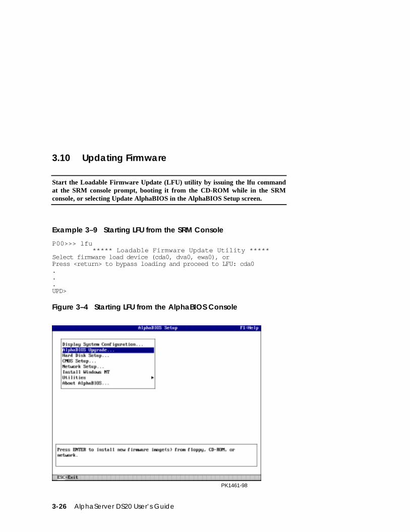
3.10 Updating Firmware
Start the Loadable Firmware Update (LFU) utility by issuing the lfu commandat the SRM console prompt, booting it from the CD-ROM while in the SRMconsole, or selecting Update AlphaBIOS in the AlphaBIOS Setup screen.
Example 3–9 Starting LFU from the SRM Console
P00>>> lfu ***** Loadable Firmware Update Utility *****Select firmware load device (cda0, dva0, ewa0), orPress <return> to bypass loading and proceed to LFU: cda0...UPD>
Figure 3–4 Starting LFU from the AlphaBIOS Console
PK1461-98

Operation 3-27
Use the Loadable Firmware Update (LFU) utility to update system firmware.
You can start LFU from either the SRM console or the AlphaBIOS console.
• From the SRM console, start LFU by issuing the lfu command (seeExample 3–9). Also from the SRM console, LFU can be booted from the AlphaCD-ROM (V5.4 or later), as shown in Example 3–10.
• From the AlphaBIOS console, select Update AlphaBIOS from the AlphaBIOSSetup screen (see Figure 3–4).
A typical update procedure is:
1. Start LFU.
2. Use the LFU list command to show the revisions of modules that LFU canupdate and the revisions of update firmware.
3. Use the LFU update command to write the new firmware.
4. Use the LFU exit command to go back to the console.
Examples of updating firmware from CD-ROM, floppy, and the network follow.
Example 3–10 Booting LFU from the CD-ROM
P00>>> show device ➊dka0.0.0.7.1 DKA0 RZ1DB-BA LYG0dka100.1.0.7.1 DKA100 RZ1CB-CA LYJ0dka500.5.0.7.1 DKA500 RRD47 1645dva0.0.0.0.0 DVA0ewa0.0.0.8.1 EWA0 00-00-F8-00-0E-3Bpka0.7.0.7.1 PKA0 SCSI Bus ID 7 5.54P00>>> boot dka500(boot dka500.5.0.7.1 -flags 0,0)block 0 of dka500.5.0.7.1 is a valid boot block..jumping to bootstrap codeThe default bootfile for this platform is [AS1400]AS1400_LFU.EXEHit <RETURN> at the prompt to use the default bootfile.Bootfile: <CR>Starting Firmware Update Utility
***** Loadable Firmware Update Utility *****.UPD>
3-28 AlphaServer DS20 User’s Guide
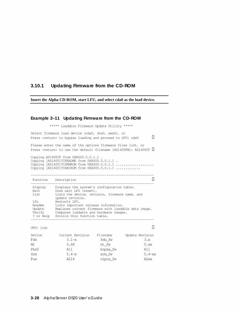
3.10.1 Updating Firmware from the CD-ROM
Insert the Alpha CD-ROM, start LFU, and select cda0 as the load device.
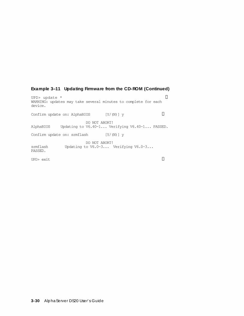
Example 3–11 Updating Firmware from the CD-ROM
***** Loadable Firmware Update Utility *****
Select firmware load device (cda0, dva0, ewa0), orPress <return> to bypass loading and proceed to LFU: cda0 ➊
Please enter the name of the options firmware files list, orPress <return> to use the default filename [AS1400FW]: AS1400CP ➋
Copying AS1400CP from DKA500.5.0.1.1 .Copying [AS1400]TCREADME from DKA500.5.0.1.1 .Copying [AS1400]TCSRMROM from DKA500.5.0.1.1 ....................Copying [AS1400]TCARCROM from DKA500.5.0.1.1 .............
----------------------------------------------------------------- Function Description ➌----------------------------------------------------------------- Display Displays the system’s configuration table. Exit Done exit LFU (reset). List Lists the device, revision, firmware name, and update revision. Lfu Restarts LFU. Readme Lists important release information. Update Replaces current firmware with loadable data image. Verify Compares loadable and hardware images. ? or Help Scrolls this function table.-----------------------------------------------------------------
UPD> list ➍
Device Current Revision Filename Update RevisionFsb 3.1-x fsb_fw 3.xNt 5.68 nt_fw 5.xxPkx0 A11 kzpsa_fw A11Srm 5.4-x srm_fw 5.4-xxPua A214 cipca_fw A2xx
Operation 3-29
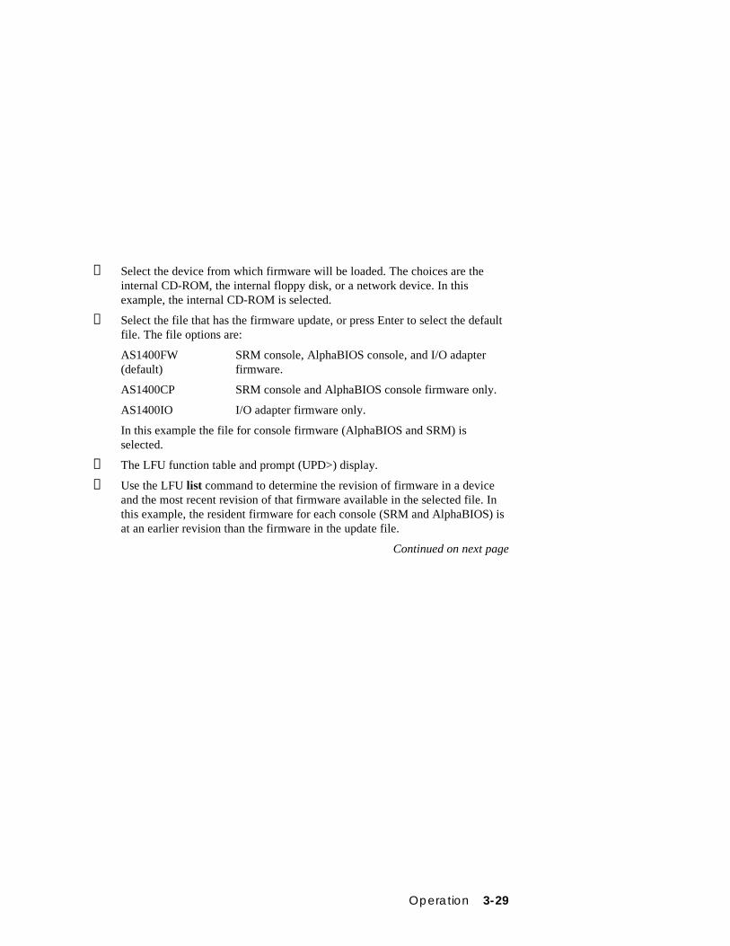
➊ Select the device from which firmware will be loaded. The choices are theinternal CD-ROM, the internal floppy disk, or a network device. In thisexample, the internal CD-ROM is selected.
➋ Select the file that has the firmware update, or press Enter to select the defaultfile. The file options are:
AS1400FW(default)
SRM console, AlphaBIOS console, and I/O adapterfirmware.
AS1400CP SRM console and AlphaBIOS console firmware only.
AS1400IO I/O adapter firmware only.
In this example the file for console firmware (AlphaBIOS and SRM) isselected.
➌ The LFU function table and prompt (UPD>) display.
➍ Use the LFU list command to determine the revision of firmware in a deviceand the most recent revision of that firmware available in the selected file. Inthis example, the resident firmware for each console (SRM and AlphaBIOS) isat an earlier revision than the firmware in the update file.
Continued on next page
3-30 AlphaServer DS20 User’s Guide
Example 3–11 Updating Firmware from the CD-ROM (Continued)
UPD> update * ➎WARNING: updates may take several minutes to complete for eachdevice.
Confirm update on: AlphaBIOS [Y/(N)] y ➏
DO NOT ABORT!AlphaBIOS Updating to V6.40-1... Verifying V6.40-1... PASSED.
Confirm update on: srmflash [Y/(N)] y
DO NOT ABORT!srmflash Updating to V6.0-3... Verifying V6.0-3...PASSED.
UPD> exit ➐
Operation 3-31
➎ The update command updates the device specified or all devices. In thisexample, the wildcard indicates that all devices supported by the selectedupdate file will be updated.
➏ For each device, you are asked to confirm that you want to update thefirmware. The default is no. Once the update begins, do not abort theoperation. Doing so will corrupt the firmware on the module.
➐ The exit command returns you to the console from which you entered LFU(either SRM or AlphaBIOS).
3-32 AlphaServer DS20 User’s Guide
3.10.2 Updating Firmware from Floppy Disk — Creatingthe Diskettes
Create the update diskettes before starting LFU. See Section 3.10.3 for anexample of the update procedure.
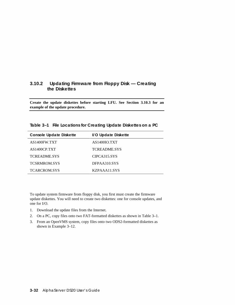
Table 3–1 File Locations for Creating Update Diskettes on a PC
Console Update Diskette I/O Update Diskette
AS1400FW.TXT AS1400IO.TXT
AS1400CP.TXT TCREADME.SYS
TCREADME.SYS CIPCA315.SYS
TCSRMROM.SYS DFPAA310.SYS
TCARCROM.SYS KZPAAA11.SYS
To update system firmware from floppy disk, you first must create the firmwareupdate diskettes. You will need to create two diskettes: one for console updates, andone for I/O.
1. Download the update files from the Internet.
2. On a PC, copy files onto two FAT-formatted diskettes as shown in Table 3–1.
3. From an OpenVMS system, copy files onto two ODS2-formatted diskettes asshown in Example 3–12.
Operation 3-33
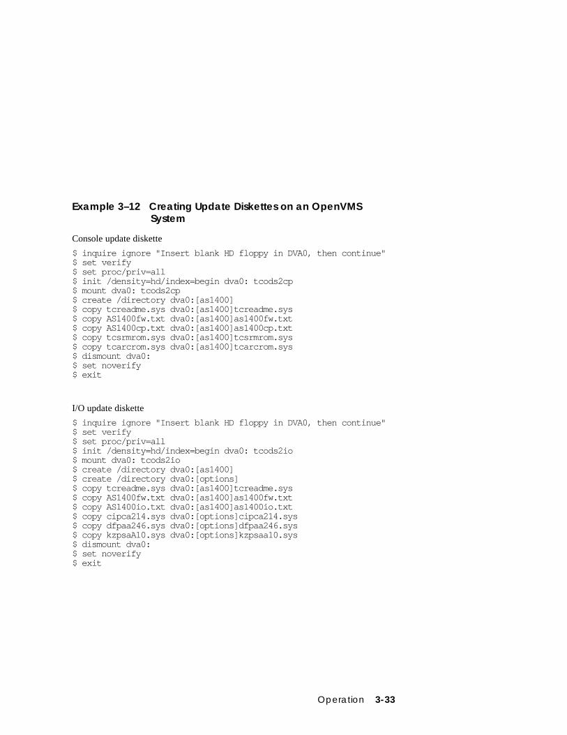
Example 3–12 Creating Update Diskettes on an OpenVMSSystem
Console update diskette
$ inquire ignore "Insert blank HD floppy in DVA0, then continue"$ set verify$ set proc/priv=all$ init /density=hd/index=begin dva0: tcods2cp$ mount dva0: tcods2cp$ create /directory dva0:[as1400]$ copy tcreadme.sys dva0:[as1400]tcreadme.sys$ copy AS1400fw.txt dva0:[as1400]as1400fw.txt$ copy AS1400cp.txt dva0:[as1400]as1400cp.txt$ copy tcsrmrom.sys dva0:[as1400]tcsrmrom.sys$ copy tcarcrom.sys dva0:[as1400]tcarcrom.sys$ dismount dva0:$ set noverify$ exit
I/O update diskette
$ inquire ignore "Insert blank HD floppy in DVA0, then continue"$ set verify$ set proc/priv=all$ init /density=hd/index=begin dva0: tcods2io$ mount dva0: tcods2io$ create /directory dva0:[as1400]$ create /directory dva0:[options]$ copy tcreadme.sys dva0:[as1400]tcreadme.sys$ copy AS1400fw.txt dva0:[as1400]as1400fw.txt$ copy AS1400io.txt dva0:[as1400]as1400io.txt$ copy cipca214.sys dva0:[options]cipca214.sys$ copy dfpaa246.sys dva0:[options]dfpaa246.sys$ copy kzpsaA10.sys dva0:[options]kzpsaa10.sys$ dismount dva0:$ set noverify$ exit
3-34 AlphaServer DS20 User’s Guide
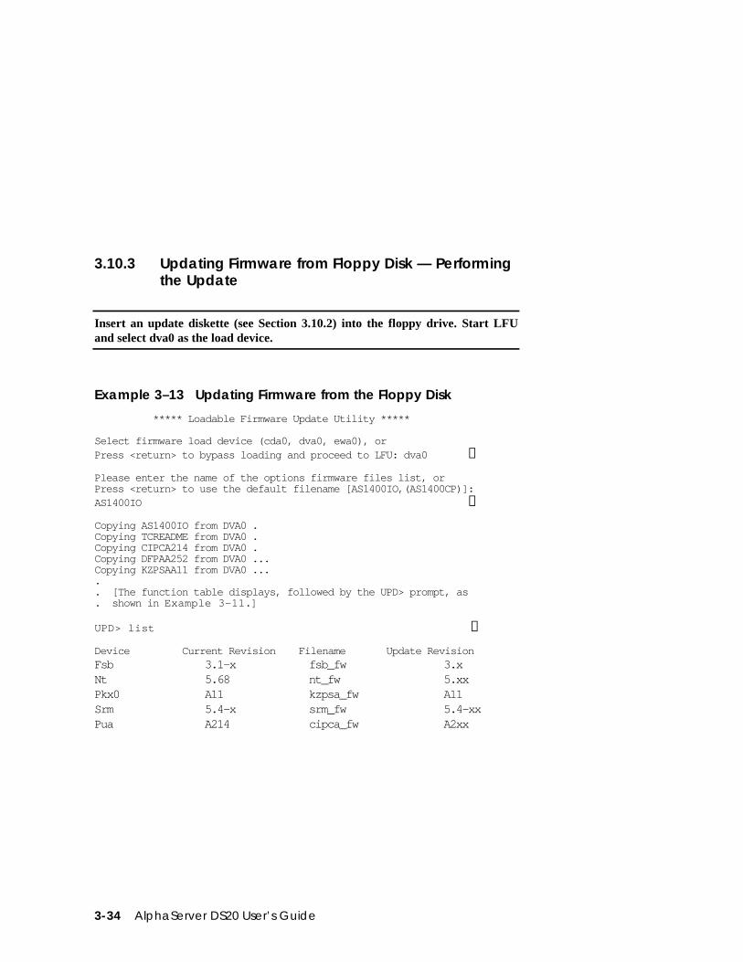
3.10.3 Updating Firmware from Floppy Disk — Performingthe Update
Insert an update diskette (see Section 3.10.2) into the floppy drive. Start LFUand select dva0 as the load device.
Example 3–13 Updating Firmware from the Floppy Disk
***** Loadable Firmware Update Utility *****
Select firmware load device (cda0, dva0, ewa0), orPress <return> to bypass loading and proceed to LFU: dva0 ➊
Please enter the name of the options firmware files list, orPress <return> to use the default filename [AS1400IO,(AS1400CP)]:AS1400IO ➋
Copying AS1400IO from DVA0 .Copying TCREADME from DVA0 .Copying CIPCA214 from DVA0 .Copying DFPAA252 from DVA0 ...Copying KZPSAA11 from DVA0 ..... [The function table displays, followed by the UPD> prompt, as. shown in Example 3–11.]
UPD> list ➌
Device Current Revision Filename Update RevisionFsb 3.1-x fsb_fw 3.xNt 5.68 nt_fw 5.xxPkx0 A11 kzpsa_fw A11Srm 5.4-x srm_fw 5.4-xxPua A214 cipca_fw A2xx
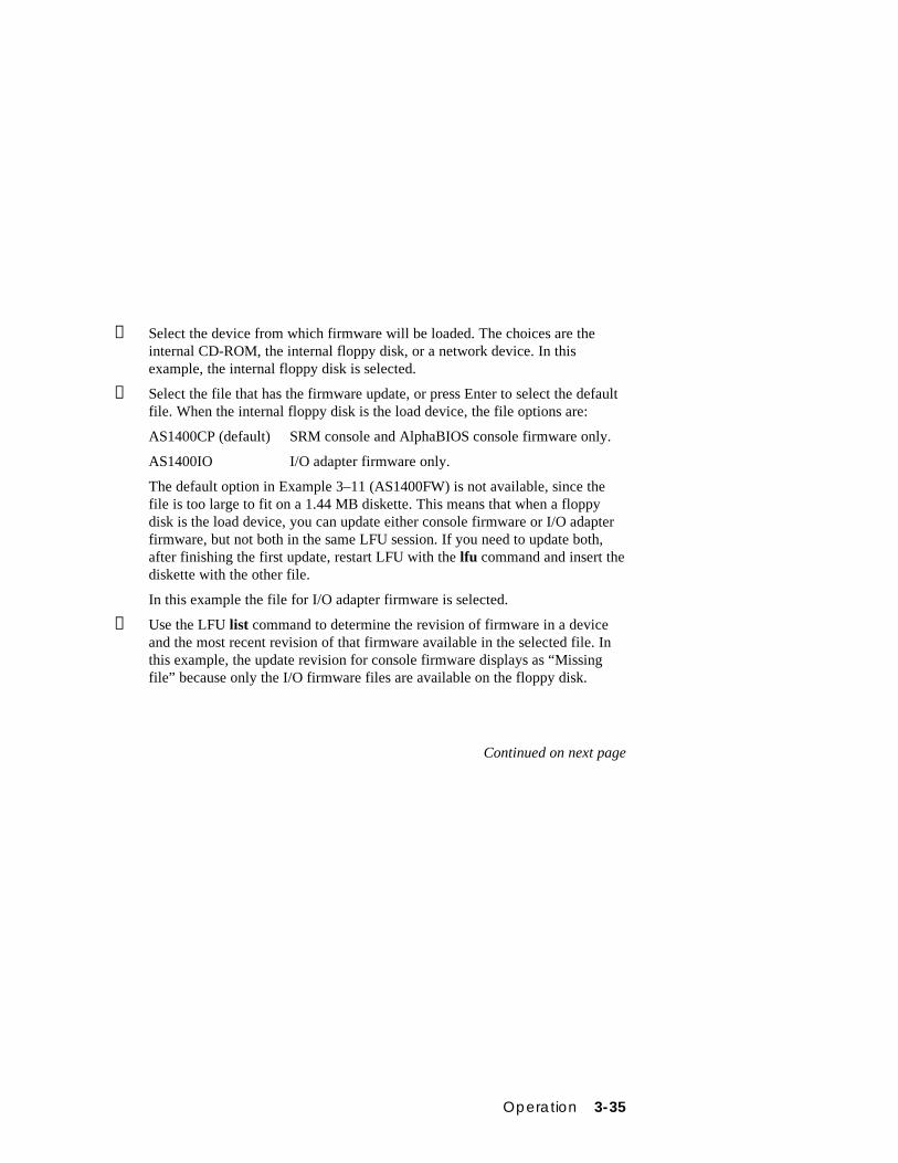
Operation 3-35
➊ Select the device from which firmware will be loaded. The choices are theinternal CD-ROM, the internal floppy disk, or a network device. In thisexample, the internal floppy disk is selected.
➋ Select the file that has the firmware update, or press Enter to select the defaultfile. When the internal floppy disk is the load device, the file options are:
AS1400CP (default) SRM console and AlphaBIOS console firmware only.
AS1400IO I/O adapter firmware only.
The default option in Example 3–11 (AS1400FW) is not available, since thefile is too large to fit on a 1.44 MB diskette. This means that when a floppydisk is the load device, you can update either console firmware or I/O adapterfirmware, but not both in the same LFU session. If you need to update both,after finishing the first update, restart LFU with the lfu command and insert thediskette with the other file.
In this example the file for I/O adapter firmware is selected.
➌ Use the LFU list command to determine the revision of firmware in a deviceand the most recent revision of that firmware available in the selected file. Inthis example, the update revision for console firmware displays as “Missingfile” because only the I/O firmware files are available on the floppy disk.
Continued on next page
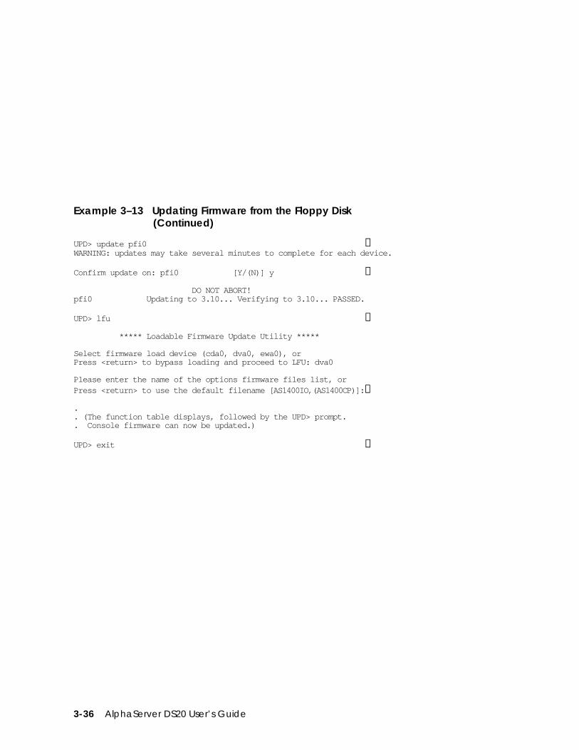
3-36 AlphaServer DS20 User’s Guide
Example 3–13 Updating Firmware from the Floppy Disk(Continued)
UPD> update pfi0 ➍WARNING: updates may take several minutes to complete for each device.
Confirm update on: pfi0 [Y/(N)] y ➎
DO NOT ABORT!pfi0 Updating to 3.10... Verifying to 3.10... PASSED.
UPD> lfu ➏
***** Loadable Firmware Update Utility *****
Select firmware load device (cda0, dva0, ewa0), orPress <return> to bypass loading and proceed to LFU: dva0
Please enter the name of the options firmware files list, orPress <return> to use the default filename [AS1400IO,(AS1400CP)]:➐
.
. (The function table displays, followed by the UPD> prompt.
. Console firmware can now be updated.)
UPD> exit ➑
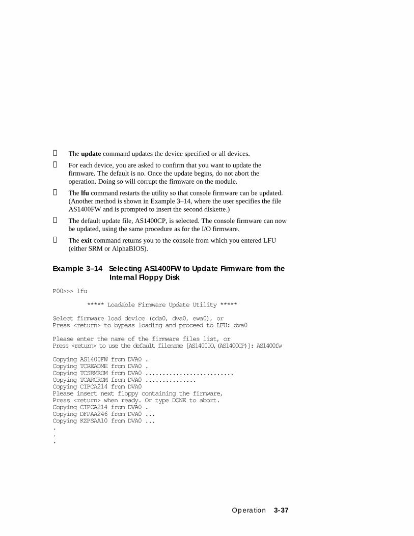
Operation 3-37
➍ The update command updates the device specified or all devices.
➎ For each device, you are asked to confirm that you want to update thefirmware. The default is no. Once the update begins, do not abort theoperation. Doing so will corrupt the firmware on the module.
➏ The lfu command restarts the utility so that console firmware can be updated.(Another method is shown in Example 3–14, where the user specifies the fileAS1400FW and is prompted to insert the second diskette.)
➐ The default update file, AS1400CP, is selected. The console firmware can nowbe updated, using the same procedure as for the I/O firmware.
➑ The exit command returns you to the console from which you entered LFU(either SRM or AlphaBIOS).
Example 3–14 Selecting AS1400FW to Update Firmware from theInternal Floppy Disk
P00>>> lfu
***** Loadable Firmware Update Utility *****
Select firmware load device (cda0, dva0, ewa0), orPress <return> to bypass loading and proceed to LFU: dva0
Please enter the name of the firmware files list, orPress <return> to use the default filename [AS1400IO,(AS1400CP)]: AS1400fw
Copying AS1400FW from DVA0 .Copying TCREADME from DVA0 .Copying TCSRMROM from DVA0 ..........................Copying TCARCROM from DVA0 ...............Copying CIPCA214 from DVA0Please insert next floppy containing the firmware,Press <return> when ready. Or type DONE to abort.Copying CIPCA214 from DVA0 .Copying DFPAA246 from DVA0 ...Copying KZPSAA10 from DVA0 ......
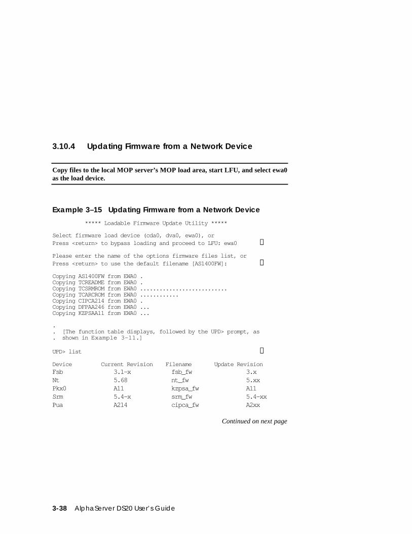
3-38 AlphaServer DS20 User’s Guide
3.10.4 Updating Firmware from a Network Device
Copy files to the local MOP server’s MOP load area, start LFU, and select ewa0as the load device.
Example 3–15 Updating Firmware from a Network Device
***** Loadable Firmware Update Utility *****
Select firmware load device (cda0, dva0, ewa0), orPress <return> to bypass loading and proceed to LFU: ewa0 ➊
Please enter the name of the options firmware files list, orPress <return> to use the default filename [AS1400FW]: ➋
Copying AS1400FW from EWA0 .Copying TCREADME from EWA0 .Copying TCSRMROM from EWA0 ...........................Copying TCARCROM from EWA0 ............Copying CIPCA214 from EWA0 .Copying DFPAA246 from EWA0 ...Copying KZPSAA11 from EWA0 ...
.
. [The function table displays, followed by the UPD> prompt, as
. shown in Example 3–11.]
UPD> list ➌
Device Current Revision Filename Update RevisionFsb 3.1-x fsb_fw 3.xNt 5.68 nt_fw 5.xxPkx0 A11 kzpsa_fw A11Srm 5.4-x srm_fw 5.4-xxPua A214 cipca_fw A2xx
Continued on next page
Operation 3-39
Before starting LFU, download the update files from the Internet. You will need thefiles with the extension .SYS. Copy these files to your local MOP server’s MOP loadarea.
➊ Select the device from which firmware will be loaded. The choices are the CD-ROM, the internal floppy disk, or a network device. In this example, a networkdevice is selected.
➋ Select the file that has the firmware update, or press Enter to select the defaultfile. The file options are:
AS1400FW(default)
SRM console, AlphaBIOS console, and I/O adapterfirmware.
AS1400CP SRM console and AlphaBIOS console firmware only.
AS1400IO I/O adapter firmware only.
In this example the default file, which has both console firmware (AlphaBIOSand SRM) and I/O adapter firmware, is selected.
➌ Use the LFU list command to determine the revision of firmware in a deviceand the most recent revision of that firmware available in the selected file. Inthis example, the resident firmware for each console (SRM and AlphaBIOS)and I/O adapter is at an earlier revision than the firmware in the update file.
Continued on next page
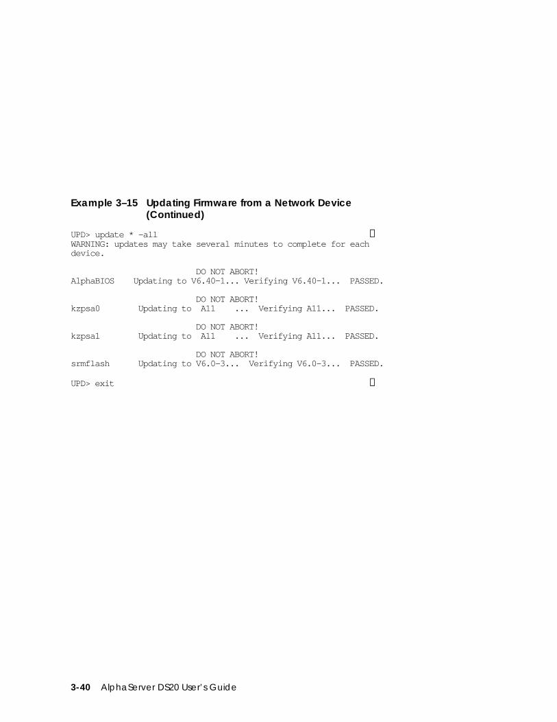
3-40 AlphaServer DS20 User’s Guide
Example 3–15 Updating Firmware from a Network Device(Continued)
UPD> update * -all ➍WARNING: updates may take several minutes to complete for eachdevice.
DO NOT ABORT!AlphaBIOS Updating to V6.40-1... Verifying V6.40-1... PASSED.
DO NOT ABORT!kzpsa0 Updating to A11 ... Verifying A11... PASSED.
DO NOT ABORT!kzpsa1 Updating to A11 ... Verifying A11... PASSED.
DO NOT ABORT!srmflash Updating to V6.0-3... Verifying V6.0-3... PASSED.
UPD> exit ➎
Operation 3-41
➍ The update command updates the device specified or all devices. In thisexample, the wildcard indicates that all devices supported by the selectedupdate file will be updated. Typically LFU requests confirmation beforeupdating each console’s or device’s firmware. The -all option eliminates theupdate confirmation requests.
➎ The exit command returns you to the console from which you entered LFU(either SRM or AlphaBIOS).
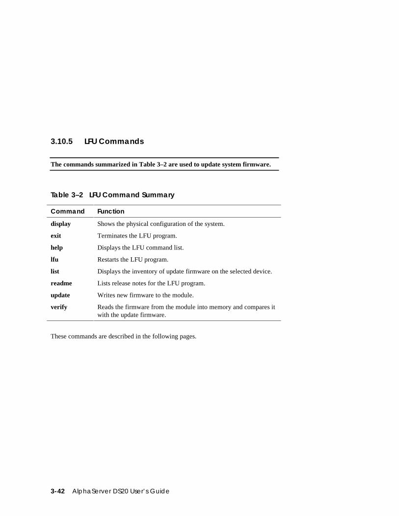
3-42 AlphaServer DS20 User’s Guide
3.10.5 LFU Commands
The commands summarized in Table 3–2 are used to update system firmware.
Table 3–2 LFU Command Summary
Command Function
display Shows the physical configuration of the system.
exit Terminates the LFU program.
help Displays the LFU command list.
lfu Restarts the LFU program.
list Displays the inventory of update firmware on the selected device.
readme Lists release notes for the LFU program.
update Writes new firmware to the module.
verify Reads the firmware from the module into memory and compares itwith the update firmware.
These commands are described in the following pages.
Operation 3-43
display
The display command shows the physical configuration of the system. Display isequivalent to issuing the SRM console command show configuration. Because itshows the slot for each module, display can help you identify the location of adevice.
exit
The exit command terminates the LFU program, causes system initialization andtesting, and returns the system to the console from which LFU was called.
help
The help (or ?) command displays the LFU command list,shown below.
--------------------------------------------------------------------- Function Description--------------------------------------------------------------------- Display Displays the system’s configuration table. Exit Done exit LFU (reset). List Lists the device, revision, firmware name, and update revision. Lfu Restarts LFU. Readme Lists important release information. Update Replaces current firmware with loadable data image. Verify Compares loadable and hardware images. ? or Help Scrolls this function table.---------------------------------------------------------------------
lfu
The lfu command restarts the LFU program. This command is used when the updatefiles are on a floppy disk. The files for updating both console firmware and I/Ofirmware are too large to fit on a 1.44 MB disk, so only one type of firmware can beupdated at a time. Restarting LFU enables you to specify another update file.
3-44 AlphaServer DS20 User’s Guide
list
The list command displays the inventory of update firmware on the CD-ROM,network, or floppy. Only the devices listed at your terminal are supported forfirmware updates.
The list command shows three pieces of information for each device:
• Current Revision — The revision of the device’s current firmware
• Filename — The name of the file used to update that firmware
• Update Revision — The revision of the firmware update image
readme
The readme command lists release notes for the LFU program.
update
The update command writes new firmware to the module. Then LFU automaticallyverifies the update by reading the new firmware image from the module intomemory and comparing it with the source image.
To update more than one device, you may use a wildcard but not a list. For example,update k* updates all devices with names beginning with k, and update * updatesall devices. When you do not specify a device name, LFU tries to update all devices;it lists the selected devices to update and prompts before devices are updated. (Thedefault is no.) The -all option eliminates the update confirmation requests, enablingthe update to proceed without operator intervention.
CAUTION: Never abort an update operation. Aborting corrupts the firmware onthe module.
verify
The verify command reads the firmware from the module into memory andcompares it with the update firmware. If a module already verified successfully whenyou updated it, but later failed tests, you can use verify to tell whether the firmwarehas become corrupted.
Operation 3-45
3.11 Hard Disk Partitioning for Windows NT
The recommended hard disk partition on the first hard disk in your system is:partition 1 should be 6 megabytes less than the total size of the drive (this largepartition holds the operating system and the application and data files) andpartition 2 should be the remaining 6 megabytes (this small partition holds onlythe few files necessary for your computer to boot).
This arrangement provides two benefits:
• AlphaBIOS requires that a boot partition be formatted with the FAT file system.However, the Windows NT file system (NTFS) provides advantages over FAT,such as additional security and more efficient use of disk space. By keeping theFAT boot partition as small as possible, the maximum amount of space is leftavailable for use as an NTFS partition.
• Most applications install themselves onto drive C by default. Although theprogram installation drive is usually configurable by the user, many peopleaccept the default of drive C. By making the first partition large, drive Cbecomes the larger drive. This arrangement makes program installation easierand avoids time-consuming insufficient disk space mistakes.
3.11.1 Hard Disk Error Conditions
Disk Initialization Failed
When you start hard disk setup, if you receive an “Internal error occurred” message,it means that a disk was found, but there was an error in communicating with thedisk. The likely conditions that can cause this error are:
• Incompatible or failed disk cables. You may not have the correct cable installed,or the cable might have a broken lead or connector. Try another cable known tobe good.
• Disk controller not configured. You may have to run a configuration utility toset up your hard disk controller. Check your controller documentation.
• Disk controller malfunction. Most controllers come with a diagnostic utility totest controller functioning. If a controller error is found, call the manufacturerfor a replacement.
• Improper SCSI termination. Many SCSI controllers require that the terminatingresistor packs be removed from all drives between the controller and last drive.Only the controller itself, and the last drive connected to the controller (the endsof the “chain”), should have terminating resistor packs left on.
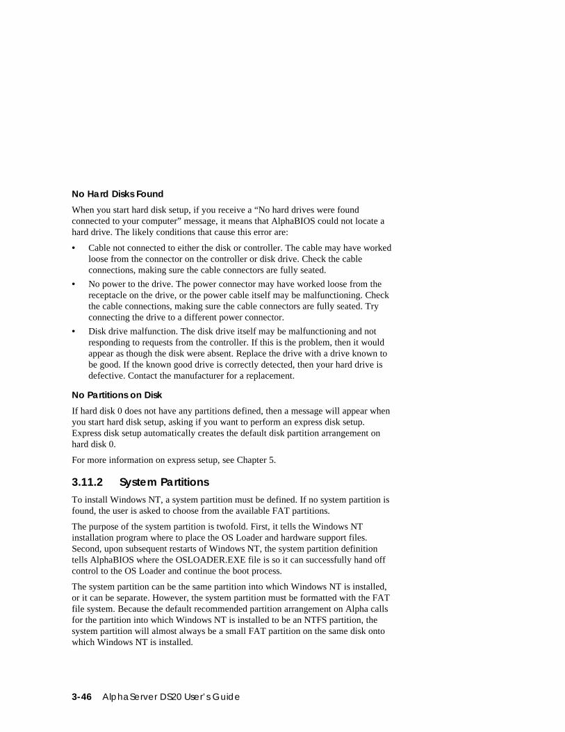
3-46 AlphaServer DS20 User’s Guide
No Hard Disks Found
When you start hard disk setup, if you receive a “No hard drives were foundconnected to your computer” message, it means that AlphaBIOS could not locate ahard drive. The likely conditions that cause this error are:
• Cable not connected to either the disk or controller. The cable may have workedloose from the connector on the controller or disk drive. Check the cableconnections, making sure the cable connectors are fully seated.
• No power to the drive. The power connector may have worked loose from thereceptacle on the drive, or the power cable itself may be malfunctioning. Checkthe cable connections, making sure the cable connectors are fully seated. Tryconnecting the drive to a different power connector.
• Disk drive malfunction. The disk drive itself may be malfunctioning and notresponding to requests from the controller. If this is the problem, then it wouldappear as though the disk were absent. Replace the drive with a drive known tobe good. If the known good drive is correctly detected, then your hard drive isdefective. Contact the manufacturer for a replacement.
No Partitions on Disk
If hard disk 0 does not have any partitions defined, then a message will appear whenyou start hard disk setup, asking if you want to perform an express disk setup.Express disk setup automatically creates the default disk partition arrangement onhard disk 0.
For more information on express setup, see Chapter 5.
3.11.2 System PartitionsTo install Windows NT, a system partition must be defined. If no system partition isfound, the user is asked to choose from the available FAT partitions.
The purpose of the system partition is twofold. First, it tells the Windows NTinstallation program where to place the OS Loader and hardware support files.Second, upon subsequent restarts of Windows NT, the system partition definitiontells AlphaBIOS where the OSLOADER.EXE file is so it can successfully hand offcontrol to the OS Loader and continue the boot process.
The system partition can be the same partition into which Windows NT is installed,or it can be separate. However, the system partition must be formatted with the FATfile system. Because the default recommended partition arrangement on Alpha callsfor the partition into which Windows NT is installed to be an NTFS partition, thesystem partition will almost always be a small FAT partition on the same disk ontowhich Windows NT is installed.
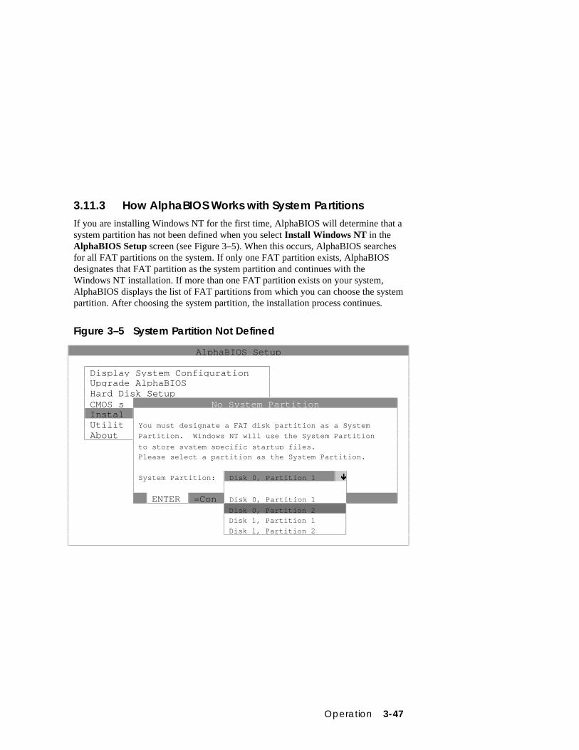
Operation 3-47
3.11.3 How AlphaBIOS Works with System PartitionsIf you are installing Windows NT for the first time, AlphaBIOS will determine that asystem partition has not been defined when you select Install Windows NT in theAlphaBIOS Setup screen (see Figure 3–5). When this occurs, AlphaBIOS searchesfor all FAT partitions on the system. If only one FAT partition exists, AlphaBIOSdesignates that FAT partition as the system partition and continues with theWindows NT installation. If more than one FAT partition exists on your system,AlphaBIOS displays the list of FAT partitions from which you can choose the systempartition. After choosing the system partition, the installation process continues.
Figure 3–5 System Partition Not Defined
AlphaBIOS Setup
Display System ConfigurationUpgrade AlphaBIOSHard Disk SetupCMOS s No System PartitionInstalUtilit You must designate a FAT disk partition as a System
About Partition. Windows NT will use the System Partition
to store system specific startup files.
Please select a partition as the System Partition.
System Partition: Disk 0, Partition 1 Ò
ENTER =Con Disk 0, Partition 1
Disk 0, Partition 2
Disk 1, Partition 1
Disk 1, Partition 2
3-48 AlphaServer DS20 User’s Guide
3.12 Using the Halt Button
Use the Halt button to halt the DIGITAL UNIX or OpenVMS operating systemwhen it hangs, clear the SRM console password, or force a halt assertion, asdescribed in Section 3.12.
Using Halt to Shut Down the Operating System
You can use the Halt button if the DIGITAL UNIX or OpenVMS operating systemhangs. Pressing the Halt button halts the operating system back to the SRM consolefirmware. From the console, you can use the crash command to force a crash dumpat the operating system level. See Section 4.11 for an example.
The Windows NT operating system does not support halts on this system. Pressingthe Halt button during a Windows NT session has no effect.
Using Halt to Clear the Console Password
The SRM console firmware allows you to set a password to prevent unauthorizedaccess to the console. If you forget the password, the Halt button, with the logincommand, lets you clear the password and regain control of the console. Section 4.8describes the procedure (page 4-29).
Operation 3-49
3.13 Halt Assertion
A halt assertion allows you to disable automatic boots of the operating system sothat you can perform tasks from the SRM console.
Under certain conditions, you might want to force a “halt assertion.” A halt assertiondiffers from a simple halt in that the SRM console “remembers” the halt. The nexttime you power up, the system ignores the SRM power-up script (nvram) and ignoresany environment variables that you have set to cause an automatic boot of theoperating system. The SRM console displays this message:
Halt assertion detectedNVRAM power-up script not executedAUTO_ACTION=BOOT/RESTART and OS_TYPE=NT ignored, if applicable
Halt assertion is useful for disabling automatic boots of the operating system whenyou want to perform tasks from the SRM console. It is also useful for disabling theSRM power-up script if you have accidentally inserted a command in the script thatwill cause a system problem. These conditions are described in the sections“Disabling Autoboot” and “Disabling the SRM Power-Up Script.”
You can force a halt assertion using the Halt button, the RCM halt command, or theRCM haltin command. Observe the following guidelines for forcing a haltassertion.
Halt Assertion with Halt Button or RCM Halt Command
Press the Halt button on the local system (or enter the RCM halt command from aremote system) approximately five seconds after starting power up or when the SRMconsole is running. The system halts at the SRM console, and the halt status issaved. The next time the system powers up, the saved halt status is checked.
NOTE: Wait 5 seconds after the system begins powering up before pressing the Halt button or remotely entering the RCM halt command. Press the button forseveral seconds.
Halt Assertion with RCM Haltin Command
Enter the RCM haltin command at any time except during power-up. For example,enter haltin during an operating system session or when the AlphaBIOS console isrunning.
If you enter the RCM haltin command during a DIGITAL UNIX or OpenVMSsession, the system halts back to the SRM console, and the halt status is saved. Thenext time the system powers up, the saved halt status is checked.
3-50 AlphaServer DS20 User’s Guide
If you enter the RCM haltin command when Windows NT or AlphaBIOS is running,the interrupt is ignored. However, you can enter the RCM haltin command followedby the RCM reset command to force a halt assertion. Upon reset, the system powersup to the SRM console, but the SRM console does not load the AlphaBIOS console.
Clearing a Halt Assertion
Clear a halt assertion as follows:
• If the halt assertion was caused by pressing the Halt button or remotely enteringthe RCM halt command, the console uses the halt assertion once, then clears it.
• If the halt assertion was caused by entering the RCM haltin command, enter theRCM haltout command or cycle power on the local system.
Disabling Autoboot
The system automatically boots the selected operating system at power-up or reset ifthe following environment variables are set:
• For DIGITAL UNIX and OpenVMS, the SRM environment variables os_type,auto_action, bootdef_dev, boot_file, and boot_osflags
• For Windows NT, the SRM os_type environment variable and the Auto Startselection in the AlphaBIOS Standard CMOS Setup screen
You might want to prevent the system from autobooting so you can perform tasksfrom the SRM console. Use one of the methods described previously to force a haltassertion. When the SRM console prompt is displayed, you can enter commands toconfigure or test the system. Chapter 4 describes the SRM console commands andenvironment variables.
Disabling the SRM Power-Up Script
The system has a power-up script (file) named “nvram” that runs every time thesystem powers up. If you accidentally insert a command in the script that will causea system problem, disable the script by using one of the methods describedpreviously to force a halt assertion. When the SRM console prompt is displayed,edit the script to delete the offending command. See Section 4.4 for moreinformation on editing the nvram script.
SRM Console 4-1
Chapter 4
SRM Console
The SRM console is the command line interface that supports the DIGITAL UNIXand OpenVMS operating systems. The SRM console is used to bootstrap theoperating system, configure and test the system hardware, examine system options forerrors, and set or change environment variables.
This chapter describes the SRM commands and environment variables. Sections inthis chapter are:
• Invoking the SRM Console
• Command Summary
• Displaying the System Configuration
• Creating a Power-Up Script
• Booting the Operating System
• Configuring the System
• Testing the System
• Making the System Secure
• Stopping and Starting CPUs
• Updating Firmware
• Forcing a System Crash Dump
• Using Environment Variables
• Depositing and Examining Data
• Reading a File
• Initializing the System
• Finding Help
• Switching from SRM to AlphaBIOS Console
• Environment Variable Summary
4-2 AlphaServer DS20 User’s Guide
4.1 Invoking the SRM Console
When a system is powered up, the SRM console runs and either remains runningor passes control to another console or an operating system. If the system isalready running, invoke the SRM console by shutting down the operating systemor by pressing the Halt button on the control panel.
In a system running the DIGITAL UNIX or OpenVMS Alpha operating system, doone of the following steps to invoke the SRM console mode:
• Shut down the operating system according to the procedure described in youroperating system documentation. The SRM console prompt, P00>>>, will bedisplayed.
• Press the Halt button on the control panel, if your system is running eitherOpenVMS or DIGITAL UNIX. The console prompt, P00>>>, will be displayed.
If you are in AlphaBIOS and want to switch to the SRM console, do one of thefollowing steps:
• Select either OpenVMS console (SRM) or DIGITAL UNIX console (SRM)from the Console Selection in the Advanced CMOS Setup screen. Save thesetting by pressing the F10 key and reset the system to start the SRM console.
• Press the Reset button, wait 5 seconds, and then press the Halt button. The SRMconsole will boot.
After you have performed tasks in the console mode, you must boot the operatingsystem with the boot command to go back to the operating mode.
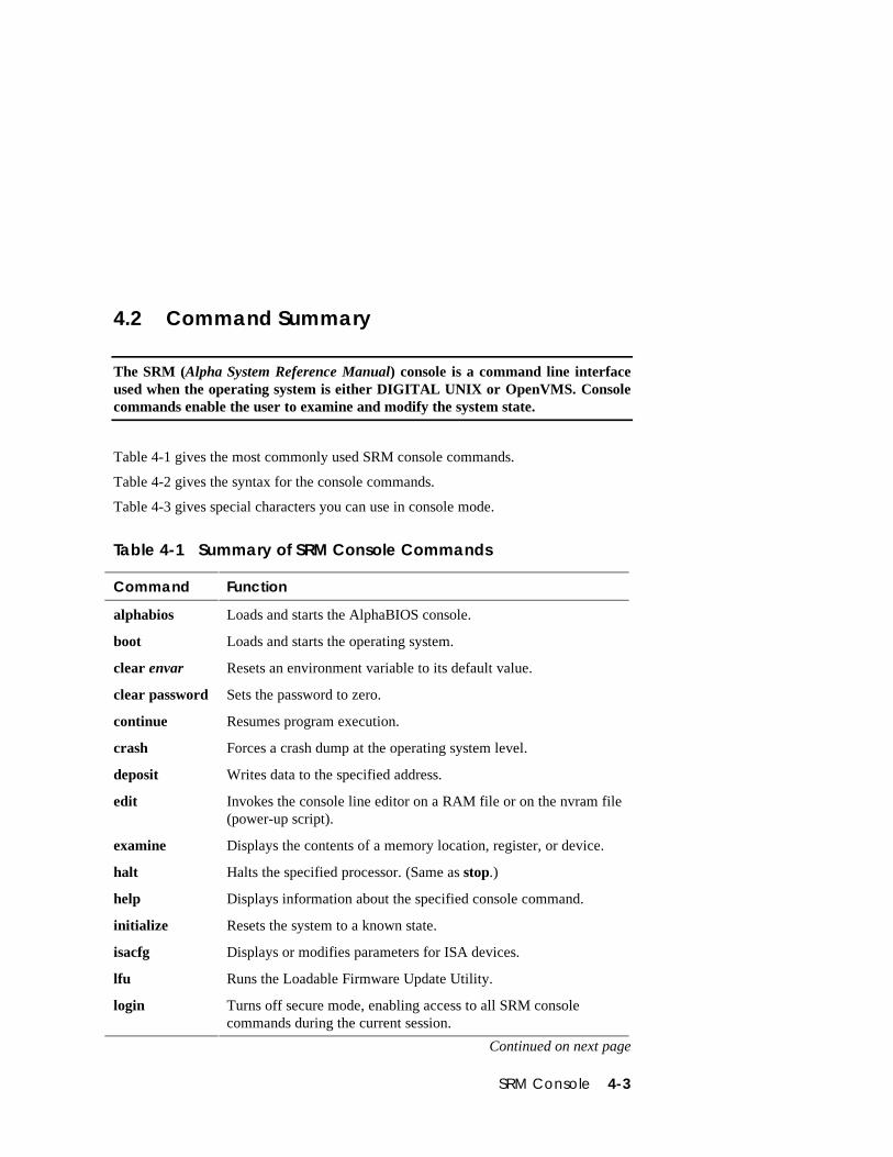
SRM Console 4-3
4.2 Command Summary
The SRM (Alpha System Reference Manual) console is a command line interfaceused when the operating system is either DIGITAL UNIX or OpenVMS. Consolecommands enable the user to examine and modify the system state.
Table 4-1 gives the most commonly used SRM console commands.
Table 4-2 gives the syntax for the console commands.
Table 4-3 gives special characters you can use in console mode.
Table 4-1 Summary of SRM Console Commands
Command Function
alphabios Loads and starts the AlphaBIOS console.
boot Loads and starts the operating system.
clear envar Resets an environment variable to its default value.
clear password Sets the password to zero.
continue Resumes program execution.
crash Forces a crash dump at the operating system level.
deposit Writes data to the specified address.
edit Invokes the console line editor on a RAM file or on the nvram file(power-up script).
examine Displays the contents of a memory location, register, or device.
halt Halts the specified processor. (Same as stop.)
help Displays information about the specified console command.
initialize Resets the system to a known state.
isacfg Displays or modifies parameters for ISA devices.
lfu Runs the Loadable Firmware Update Utility.
login Turns off secure mode, enabling access to all SRM consolecommands during the current session.
Continued on next page
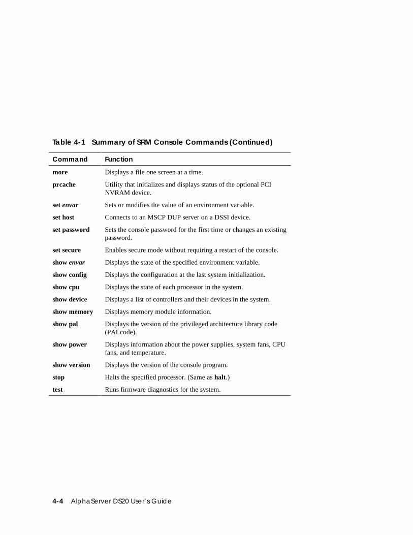
4-4 AlphaServer DS20 User’s Guide
Table 4-1 Summary of SRM Console Commands (Continued)
Command Function
more Displays a file one screen at a time.
prcache Utility that initializes and displays status of the optional PCINVRAM device.
set envar Sets or modifies the value of an environment variable.
set host Connects to an MSCP DUP server on a DSSI device.
set password Sets the console password for the first time or changes an existingpassword.
set secure Enables secure mode without requiring a restart of the console.
show envar Displays the state of the specified environment variable.
show config Displays the configuration at the last system initialization.
show cpu Displays the state of each processor in the system.
show device Displays a list of controllers and their devices in the system.
show memory Displays memory module information.
show pal Displays the version of the privileged architecture library code(PALcode).
show power Displays information about the power supplies, system fans, CPUfans, and temperature.
show version Displays the version of the console program.
stop Halts the specified processor. (Same as halt.)
test Runs firmware diagnostics for the system.
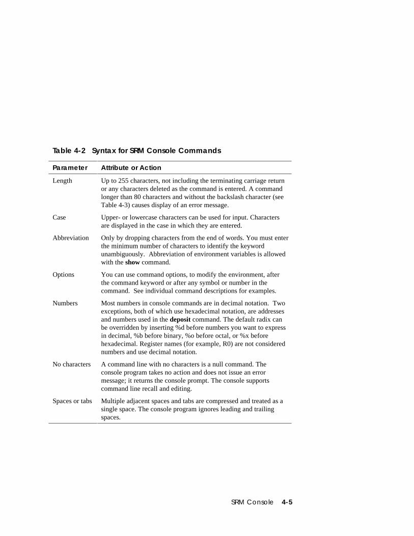
SRM Console 4-5
Table 4-2 Syntax for SRM Console Commands
Parameter Attribute or Action
Length Up to 255 characters, not including the terminating carriage returnor any characters deleted as the command is entered. A commandlonger than 80 characters and without the backslash character (seeTable 4-3) causes display of an error message.
Case Upper- or lowercase characters can be used for input. Charactersare displayed in the case in which they are entered.
Abbreviation Only by dropping characters from the end of words. You must enterthe minimum number of characters to identify the keywordunambiguously. Abbreviation of environment variables is allowedwith the show command.
Options You can use command options, to modify the environment, afterthe command keyword or after any symbol or number in thecommand. See individual command descriptions for examples.
Numbers Most numbers in console commands are in decimal notation. Twoexceptions, both of which use hexadecimal notation, are addressesand numbers used in the deposit command. The default radix canbe overridden by inserting %d before numbers you want to expressin decimal, %b before binary, %o before octal, or %x beforehexadecimal. Register names (for example, R0) are not considerednumbers and use decimal notation.
No characters A command line with no characters is a null command. Theconsole program takes no action and does not issue an errormessage; it returns the console prompt. The console supportscommand line recall and editing.
Spaces or tabs Multiple adjacent spaces and tabs are compressed and treated as asingle space. The console program ignores leading and trailingspaces.
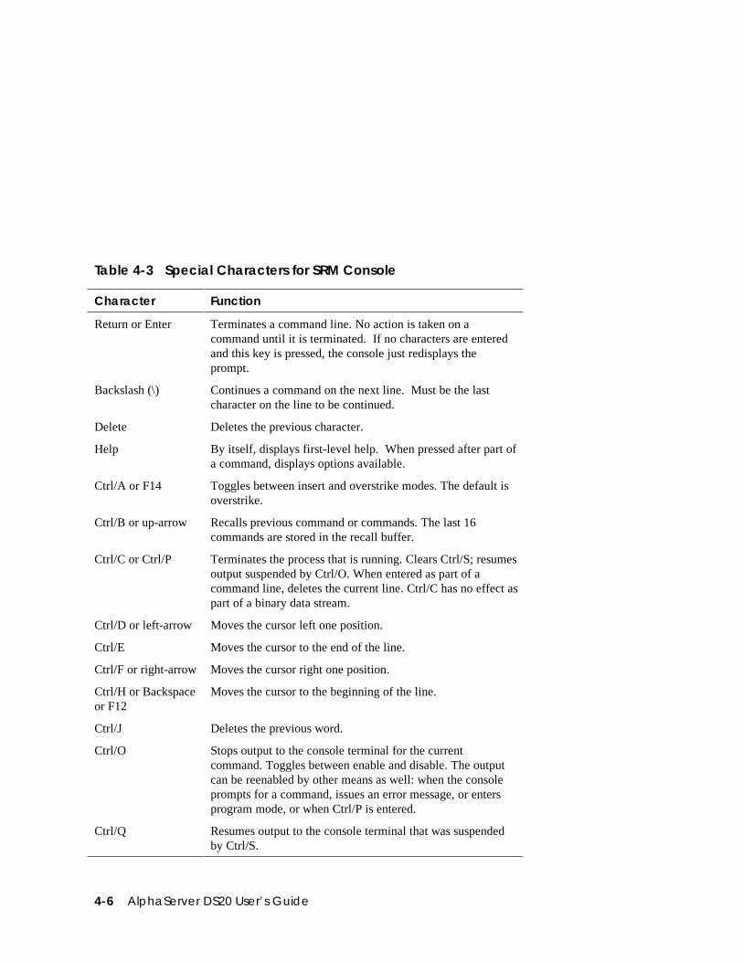
4-6 AlphaServer DS20 User’s Guide
Table 4-3 Special Characters for SRM Console
Character Function
Return or Enter Terminates a command line. No action is taken on acommand until it is terminated. If no characters are enteredand this key is pressed, the console just redisplays theprompt.
Backslash (\) Continues a command on the next line. Must be the lastcharacter on the line to be continued.
Delete Deletes the previous character.
Help By itself, displays first-level help. When pressed after part ofa command, displays options available.
Ctrl/A or F14 Toggles between insert and overstrike modes. The default isoverstrike.
Ctrl/B or up-arrow Recalls previous command or commands. The last 16commands are stored in the recall buffer.
Ctrl/C or Ctrl/P Terminates the process that is running. Clears Ctrl/S; resumesoutput suspended by Ctrl/O. When entered as part of acommand line, deletes the current line. Ctrl/C has no effect aspart of a binary data stream.
Ctrl/D or left-arrow Moves the cursor left one position.
Ctrl/E Moves the cursor to the end of the line.
Ctrl/F or right-arrow Moves the cursor right one position.
Ctrl/H or Backspaceor F12
Moves the cursor to the beginning of the line.
Ctrl/J Deletes the previous word.
Ctrl/O Stops output to the console terminal for the currentcommand. Toggles between enable and disable. The outputcan be reenabled by other means as well: when the consoleprompts for a command, issues an error message, or entersprogram mode, or when Ctrl/P is entered.
Ctrl/Q Resumes output to the console terminal that was suspendedby Ctrl/S.
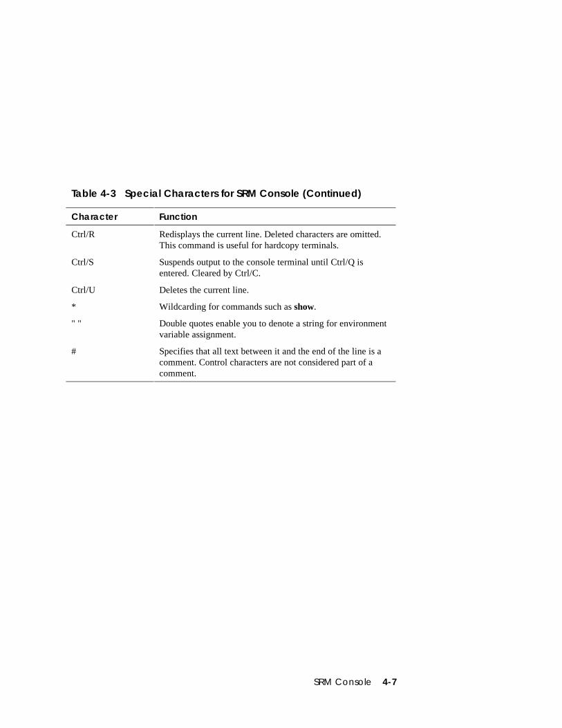
SRM Console 4-7
Table 4-3 Special Characters for SRM Console (Continued)
Character Function
Ctrl/R Redisplays the current line. Deleted characters are omitted.This command is useful for hardcopy terminals.
Ctrl/S Suspends output to the console terminal until Ctrl/Q isentered. Cleared by Ctrl/C.
Ctrl/U Deletes the current line.
* Wildcarding for commands such as show.
" " Double quotes enable you to denote a string for environmentvariable assignment.
# Specifies that all text between it and the end of the line is acomment. Control characters are not considered part of acomment.
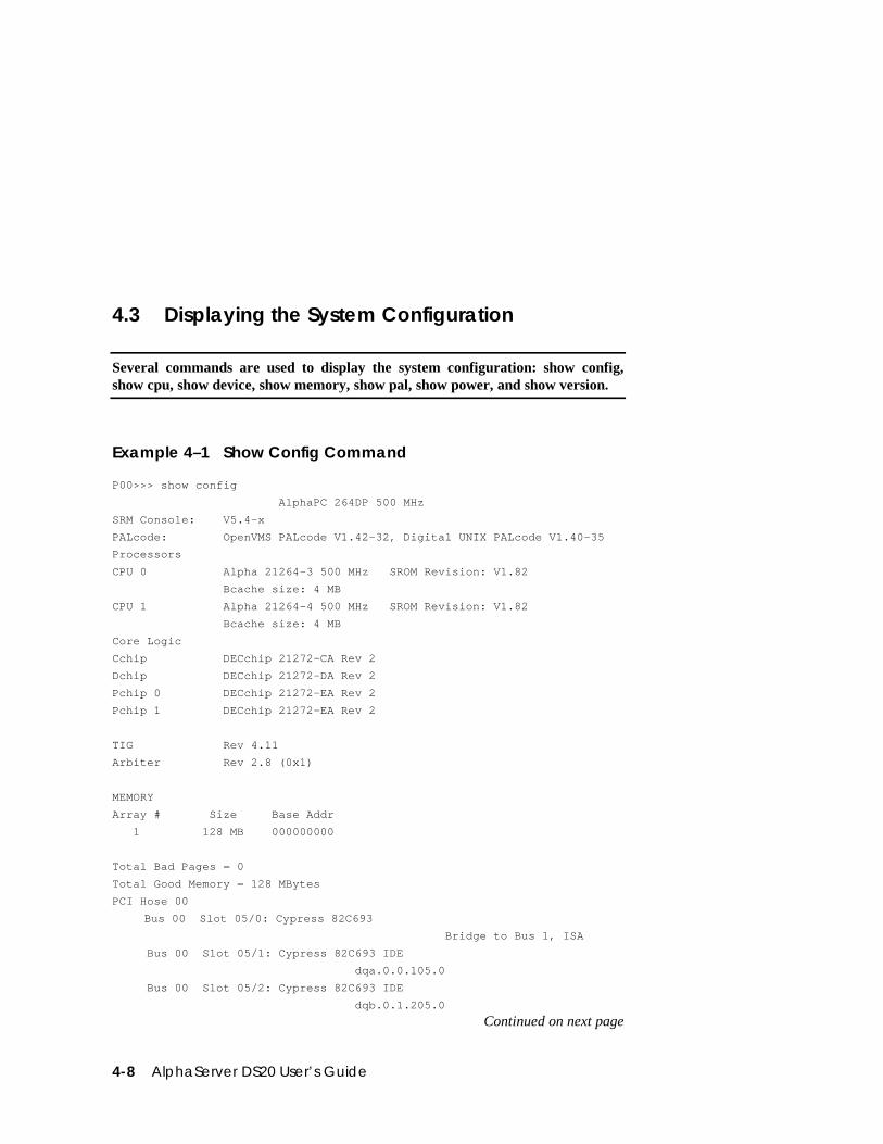
4-8 AlphaServer DS20 User’s Guide
4.3 Displaying the System Configuration
Several commands are used to display the system configuration: show config,show cpu, show device, show memory, show pal, show power, and show version.
Example 4–1 Show Config Command
P00>>> show config
AlphaPC 264DP 500 MHz
SRM Console: V5.4-x
PALcode: OpenVMS PALcode V1.42-32, Digital UNIX PALcode V1.40-35
Processors
CPU 0 Alpha 21264-3 500 MHz SROM Revision: V1.82
Bcache size: 4 MB
CPU 1 Alpha 21264-4 500 MHz SROM Revision: V1.82
Bcache size: 4 MB
Core Logic
Cchip DECchip 21272-CA Rev 2
Dchip DECchip 21272-DA Rev 2
Pchip 0 DECchip 21272-EA Rev 2
Pchip 1 DECchip 21272-EA Rev 2
TIG Rev 4.11
Arbiter Rev 2.8 (0x1)
MEMORY
Array # Size Base Addr
1 128 MB 000000000
Total Bad Pages = 0
Total Good Memory = 128 MBytes
PCI Hose 00
Bus 00 Slot 05/0: Cypress 82C693 Bridge to Bus 1, ISA
Bus 00 Slot 05/1: Cypress 82C693 IDE
dqa.0.0.105.0
Bus 00 Slot 05/2: Cypress 82C693 IDE
dqb.0.1.205.0
Continued on next page
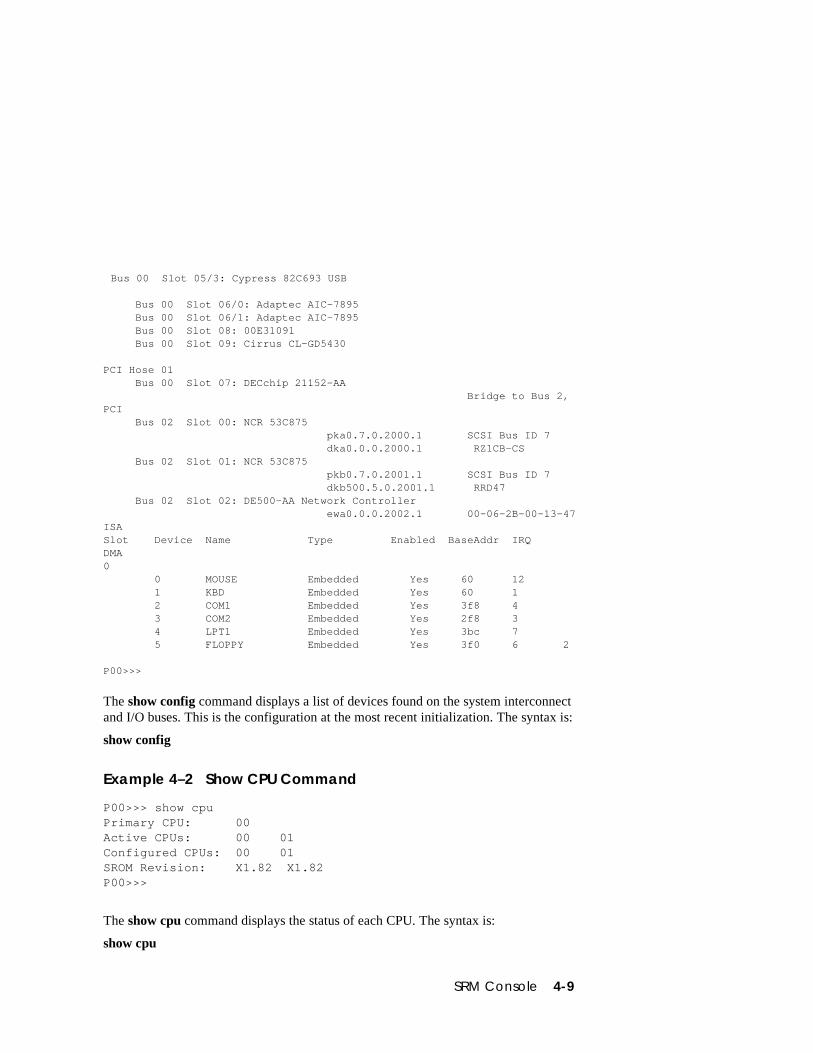
SRM Console 4-9
Bus 00 Slot 05/3: Cypress 82C693 USB
Bus 00 Slot 06/0: Adaptec AIC-7895 Bus 00 Slot 06/1: Adaptec AIC-7895 Bus 00 Slot 08: 00E31091 Bus 00 Slot 09: Cirrus CL-GD5430
PCI Hose 01 Bus 00 Slot 07: DECchip 21152-AA Bridge to Bus 2,PCI Bus 02 Slot 00: NCR 53C875 pka0.7.0.2000.1 SCSI Bus ID 7 dka0.0.0.2000.1 RZ1CB-CS Bus 02 Slot 01: NCR 53C875 pkb0.7.0.2001.1 SCSI Bus ID 7 dkb500.5.0.2001.1 RRD47 Bus 02 Slot 02: DE500-AA Network Controller ewa0.0.0.2002.1 00-06-2B-00-13-47ISASlot Device Name Type Enabled BaseAddr IRQDMA0 0 MOUSE Embedded Yes 60 12 1 KBD Embedded Yes 60 1 2 COM1 Embedded Yes 3f8 4 3 COM2 Embedded Yes 2f8 3 4 LPT1 Embedded Yes 3bc 7 5 FLOPPY Embedded Yes 3f0 6 2
P00>>>
The show config command displays a list of devices found on the system interconnectand I/O buses. This is the configuration at the most recent initialization. The syntax is:
show config
Example 4–2 Show CPU Command
P00>>> show cpuPrimary CPU: 00Active CPUs: 00 01Configured CPUs: 00 01SROM Revision: X1.82 X1.82P00>>>
The show cpu command displays the status of each CPU. The syntax is:
show cpu
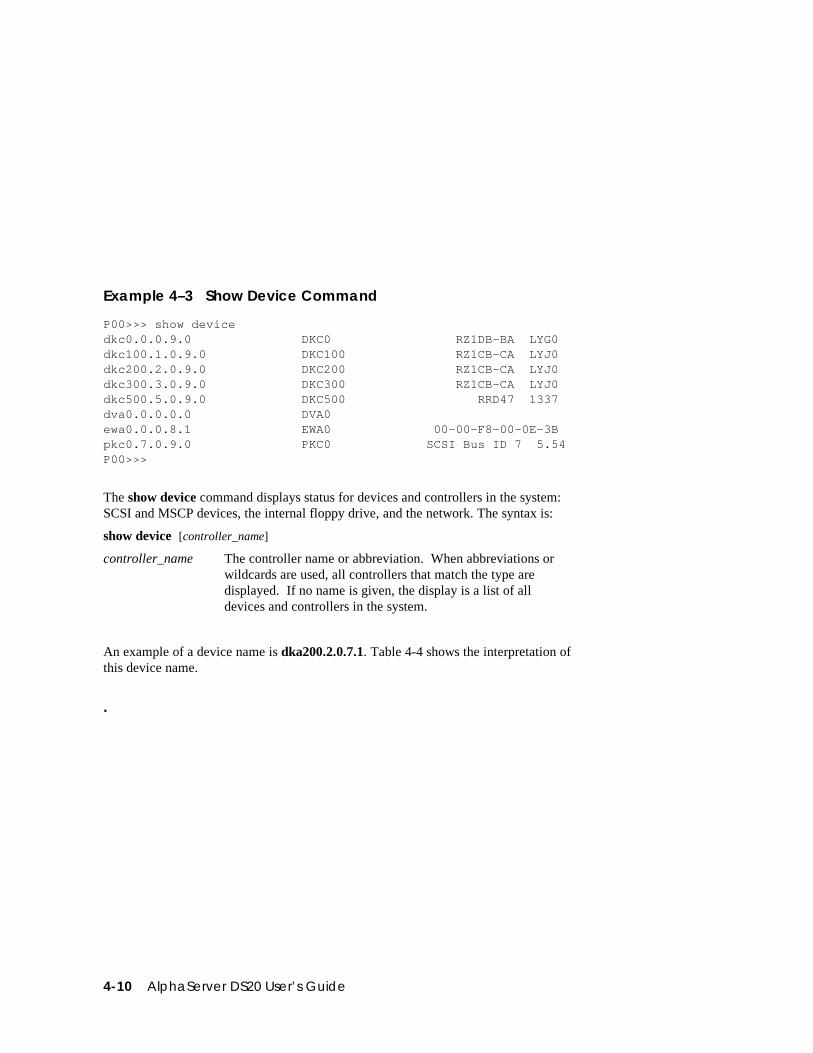
4-10 AlphaServer DS20 User’s Guide
Example 4–3 Show Device Command
P00>>> show devicedkc0.0.0.9.0 DKC0 RZ1DB-BA LYG0dkc100.1.0.9.0 DKC100 RZ1CB-CA LYJ0dkc200.2.0.9.0 DKC200 RZ1CB-CA LYJ0dkc300.3.0.9.0 DKC300 RZ1CB-CA LYJ0dkc500.5.0.9.0 DKC500 RRD47 1337dva0.0.0.0.0 DVA0ewa0.0.0.8.1 EWA0 00-00-F8-00-0E-3Bpkc0.7.0.9.0 PKC0 SCSI Bus ID 7 5.54P00>>>
The show device command displays status for devices and controllers in the system:SCSI and MSCP devices, the internal floppy drive, and the network. The syntax is:
show device [controller_name]
controller_name The controller name or abbreviation. When abbreviations orwildcards are used, all controllers that match the type aredisplayed. If no name is given, the display is a list of alldevices and controllers in the system.
An example of a device name is dka200.2.0.7.1. Table 4-4 shows the interpretation ofthis device name.
.
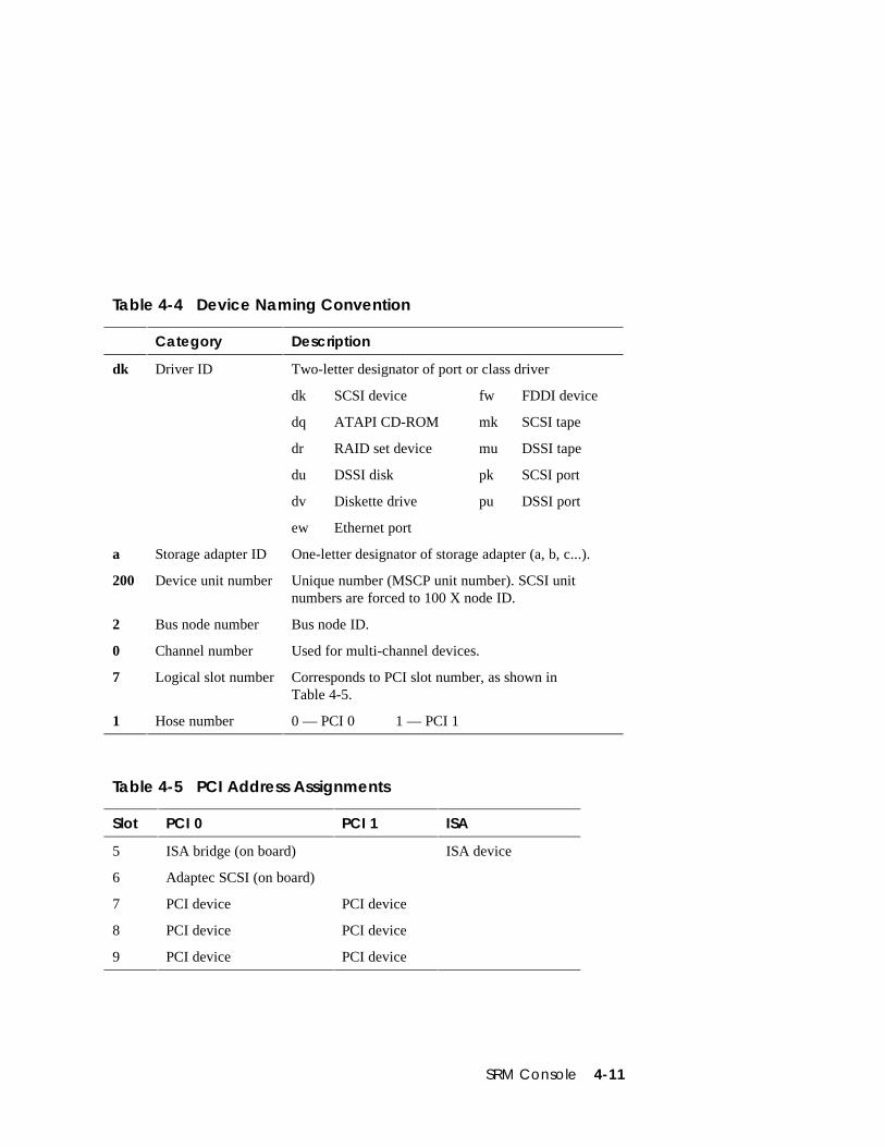
SRM Console 4-11
Table 4-4 Device Naming Convention
Category Description
dk Driver ID Two-letter designator of port or class driver
dk SCSI device fw FDDI device
dq ATAPI CD-ROM mk SCSI tape
dr RAID set device mu DSSI tape
du DSSI disk pk SCSI port
dv Diskette drive pu DSSI port
ew Ethernet port
a Storage adapter ID One-letter designator of storage adapter (a, b, c...).
200 Device unit number Unique number (MSCP unit number). SCSI unitnumbers are forced to 100 X node ID.
2 Bus node number Bus node ID.
0 Channel number Used for multi-channel devices.
7 Logical slot number Corresponds to PCI slot number, as shown inTable 4-5.
1 Hose number 0 — PCI 0 1 — PCI 1
Table 4-5 PCI Address Assignments
Slot PCI 0 PCI 1 ISA
5 ISA bridge (on board) ISA device
6 Adaptec SCSI (on board)
7 PCI device PCI device
8 PCI device PCI device
9 PCI device PCI device
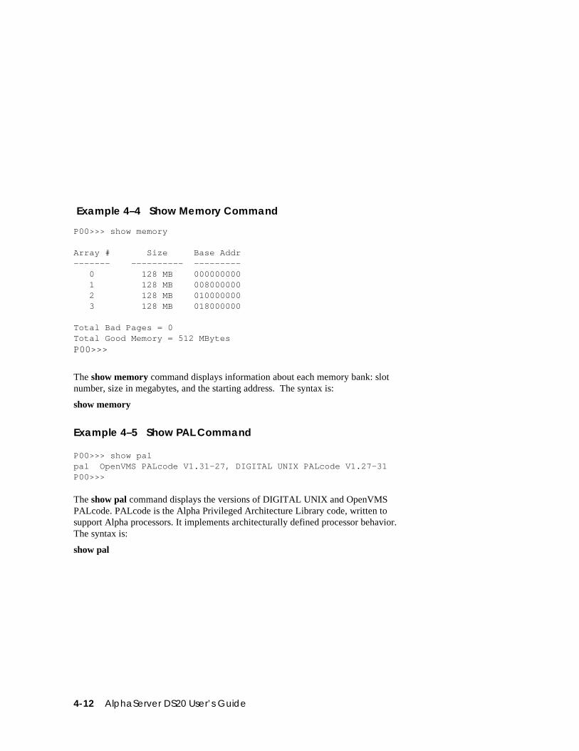
4-12 AlphaServer DS20 User’s Guide
Example 4–4 Show Memory Command
P00>>> show memory
Array # Size Base Addr------- ---------- --------- 0 128 MB 000000000 1 128 MB 008000000 2 128 MB 010000000 3 128 MB 018000000
Total Bad Pages = 0Total Good Memory = 512 MBytesP00>>>
The show memory command displays information about each memory bank: slotnumber, size in megabytes, and the starting address. The syntax is:
show memory
Example 4–5 Show PAL Command
P00>>> show palpal OpenVMS PALcode V1.31-27, DIGITAL UNIX PALcode V1.27-31P00>>>
The show pal command displays the versions of DIGITAL UNIX and OpenVMSPALcode. PALcode is the Alpha Privileged Architecture Library code, written tosupport Alpha processors. It implements architecturally defined processor behavior.The syntax is:
show pal
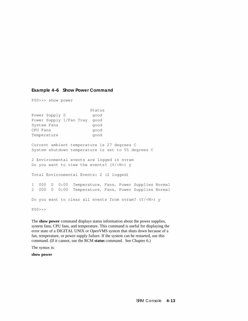
SRM Console 4-13
Example 4–6 Show Power Command
P00>>> show power
StatusPower Supply 0 goodPower Supply 1/Fan Tray goodSystem Fans goodCPU Fans goodTemperature good
Current ambient temperature is 27 degrees CSystem shutdown temperature is set to 55 degrees C
2 Environmental events are logged in nvramDo you want to view the events? (Y/<N>) y
Total Environmental Events: 2 (2 logged)
1 000 0 0:00 Temperature, Fans, Power Supplies Normal2 000 0 0:00 Temperature, Fans, Power Supplies Normal
Do you want to clear all events from nvram? (Y/<N>) y
P00>>>
The show power command displays status information about the power supplies,system fans, CPU fans, and temperature. This command is useful for displaying theerror state of a DIGITAL UNIX or OpenVMS system that shuts down because of afan, temperature, or power supply failure. If the system can be restarted, use thiscommand. (If it cannot, use the RCM status command. See Chapter 6.)
The syntax is:
show power
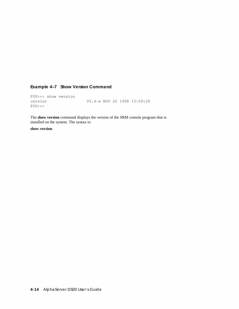
4-14 AlphaServer DS20 User’s Guide
Example 4–7 Show Version Command
P00>>> show versionversion V5.4-x NOV 20 1998 13:59:28P00>>>
The show version command displays the version of the SRM console program that isinstalled on the system. The syntax is:
show version
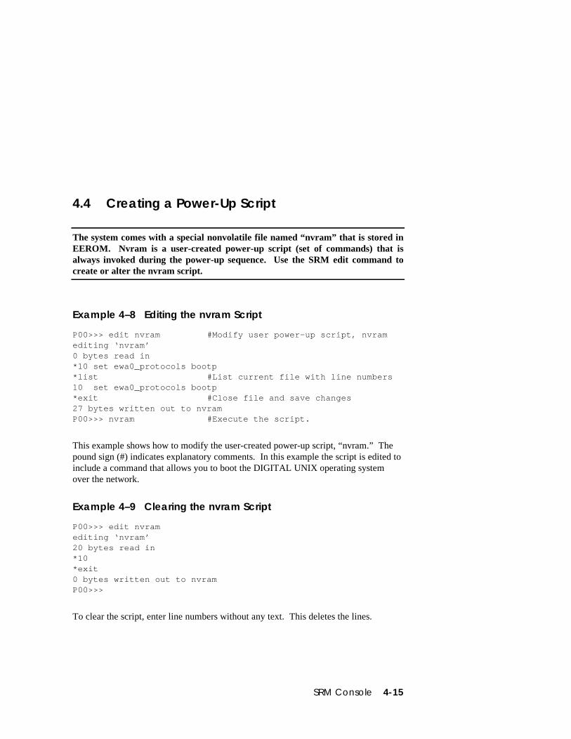
SRM Console 4-15
4.4 Creating a Power-Up Script
The system comes with a special nonvolatile file named “nvram” that is stored inEEROM. Nvram is a user-created power-up script (set of commands) that isalways invoked during the power-up sequence. Use the SRM edit command tocreate or alter the nvram script.
Example 4–8 Editing the nvram Script
P00>>> edit nvram #Modify user power-up script, nvramediting ‘nvram’0 bytes read in*10 set ewa0_protocols bootp*list #List current file with line numbers10 set ewa0_protocols bootp*exit #Close file and save changes27 bytes written out to nvramP00>>> nvram #Execute the script.
This example shows how to modify the user-created power-up script, “nvram.” Thepound sign (#) indicates explanatory comments. In this example the script is edited toinclude a command that allows you to boot the DIGITAL UNIX operating systemover the network.
Example 4–9 Clearing the nvram Script
P00>>> edit nvramediting ‘nvram’20 bytes read in*10*exit0 bytes written out to nvramP00>>>
To clear the script, enter line numbers without any text. This deletes the lines.
4-16 AlphaServer DS20 User’s Guide
Editing the Nvram Script
You can create an nvram script to include any commands you want the system toexecute at power-up.
You create and edit the nvram script using the SRM edit command. With edit, linesmay be added, overwritten, or deleted.
The syntax is:
edit file
file is the name of the file to be edited.
The editing commands are:
help Displays the brief help file.
list Lists the current file prefixed with line numbers.
renumber Renumbers the lines of the file in increments of 10.
exit Leaves the editor and closes the file, saving all changes.
quit Leaves the editor and closes the file without saving changes.
nn Deletes line number nn.
nn text Adds or overwrites line number nn with text.
NOTE: It is possible to disable the system by editing the nvram script. For example,if you include the initialize command in the script, the system will go into an endlessloop. To fix this, press the Halt button while the system is powering up. You can thenedit the script to delete the offending command.
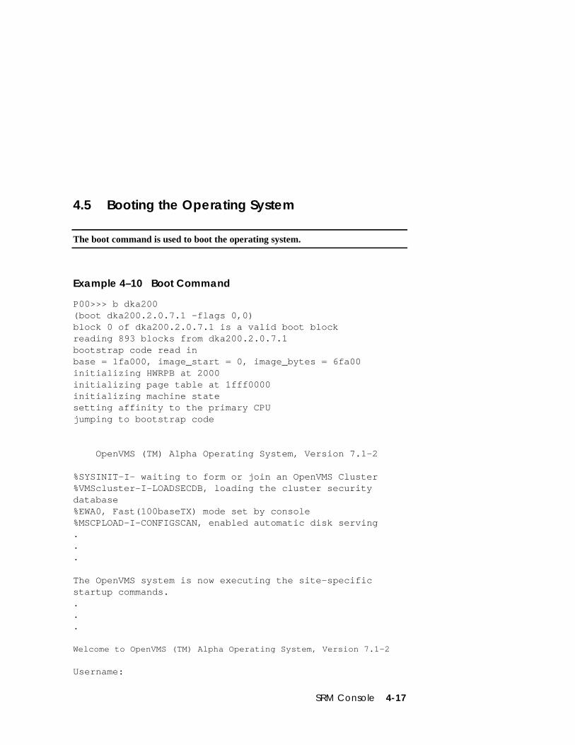
SRM Console 4-17
4.5 Booting the Operating System
The boot command is used to boot the operating system.
Example 4–10 Boot Command
P00>>> b dka200(boot dka200.2.0.7.1 -flags 0,0)block 0 of dka200.2.0.7.1 is a valid boot blockreading 893 blocks from dka200.2.0.7.1bootstrap code read inbase = 1fa000, image_start = 0, image_bytes = 6fa00initializing HWRPB at 2000initializing page table at 1fff0000initializing machine statesetting affinity to the primary CPUjumping to bootstrap code
OpenVMS (TM) Alpha Operating System, Version 7.1-2
%SYSINIT-I- waiting to form or join an OpenVMS Cluster%VMScluster-I-LOADSECDB, loading the cluster securitydatabase%EWA0, Fast(100baseTX) mode set by console%MSCPLOAD-I-CONFIGSCAN, enabled automatic disk serving...
The OpenVMS system is now executing the site-specificstartup commands....
Welcome to OpenVMS (TM) Alpha Operating System, Version 7.1-2
Username:
4-18 AlphaServer DS20 User’s Guide
The boot command initializes the processor, loads a program image from the specifiedboot device, and transfers control to that image. The syntax is:
boot [-file filename] [-flags [value]] [-halt] [-protocols enet_protocol] [boot_dev]
-file filename The boot file.
-flags [value] Specifies additional information to the loaded image oroperating system. In DIGITAL UNIX, specifies boot flags. InOpenVMS, specifies system root number and boot flags. Thisqualifier overrides the setting of the boot_osflags environmentvariable. See the boot_osflags environment variable for a list ofsettings and their meanings.
-halt Forces the bootstrap operation to halt and invoke the consoleprogram once the bootstrap image is loaded and page tables andother data structures are set up. Console device drivers are notshut down. Transfer control to the image by entering thecontinue command.
-protocolsenet_protocol
Either mop (default) or bootp. This qualifier overrides thesetting of the ew*0_protocols environment variable.
boot_dev A device path or list of devices from which the console programattempts to boot, or a saved boot specification in the form of anenvironment variable. This qualifier overrides the setting of thebootdef_dev environment variable. Use the bootdef_devenvironment variable to define the default boot device string.
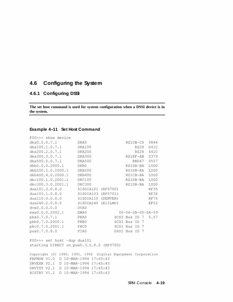
SRM Console 4-19
4.6 Configuring the System
4.6.1 Configuring DSSI
The set host command is used for system configuration when a DSSI device is inthe system.
Example 4–11 Set Host Command
P00>>> show devicedka0.0.0.7.1 DKA0 RZ1CB-CS 0844dka100.1.0.7.1 DKA100 RZ28 D41Cdka200.2.0.7.1 DKA200 RZ28 441Cdka300.3.0.7.1 DKA300 RZ1EF-AB 0370dka500.5.0.7.1 DKA500 RRD47 0557dkb0.0.0.2000.1 DKB0 RZ1DB-BA LYG0dkb200.2.0.2000.1 DKB200 RZ1DB-BA LYG0dkb400.4.0.2000.1 DKB400 RZ1CB-BA LYG0dkc100.1.0.2001.1 DKC100 RZ1DB-BA LYG0dkc300.3.0.2001.1 DKC300 RZ1DB-BA LYG0dua101.3.0.8.0 $1$DIA101 (RF0700) RF35dua103.1.0.8.0 $1$DIA103 (RF0701) RF36dua110.0.0.8.0 $1$DIA110 (DENVER) RF74dua240.2.0.8.0 $1$DIA240 (E1ILMO) EF52dva0.0.0.0.0 DVA0ewa0.0.0.2002.1 EWA0 00-06-2B-00-0A-59pka0.7.0.7.1 PKA0 SCSI Bus ID 7 5.57pkb0.7.0.2000.1 PKB0 SCSI Bus ID 7pkc0.7.0.2001.1 PKC0 SCSI Bus ID 7pua0.7.0.8.0 PIA0 DSSI Bus ID 7
P00>>> set host -dup dua101starting DIRECT on pua0.3.0.8.0 (RF0700)
Copyright (C) 1990, 1991, 1992 Digital Equipment CorporationPRFMON V1.0 D 10-MAR-1994 17:45:43DRVEXR V2.1 D 10-MAR-1994 17:45:43DRVTST V2.1 D 10-MAR-1994 17:45:43HISTRY V1.2 D 10-MAR-1994 17:45:43
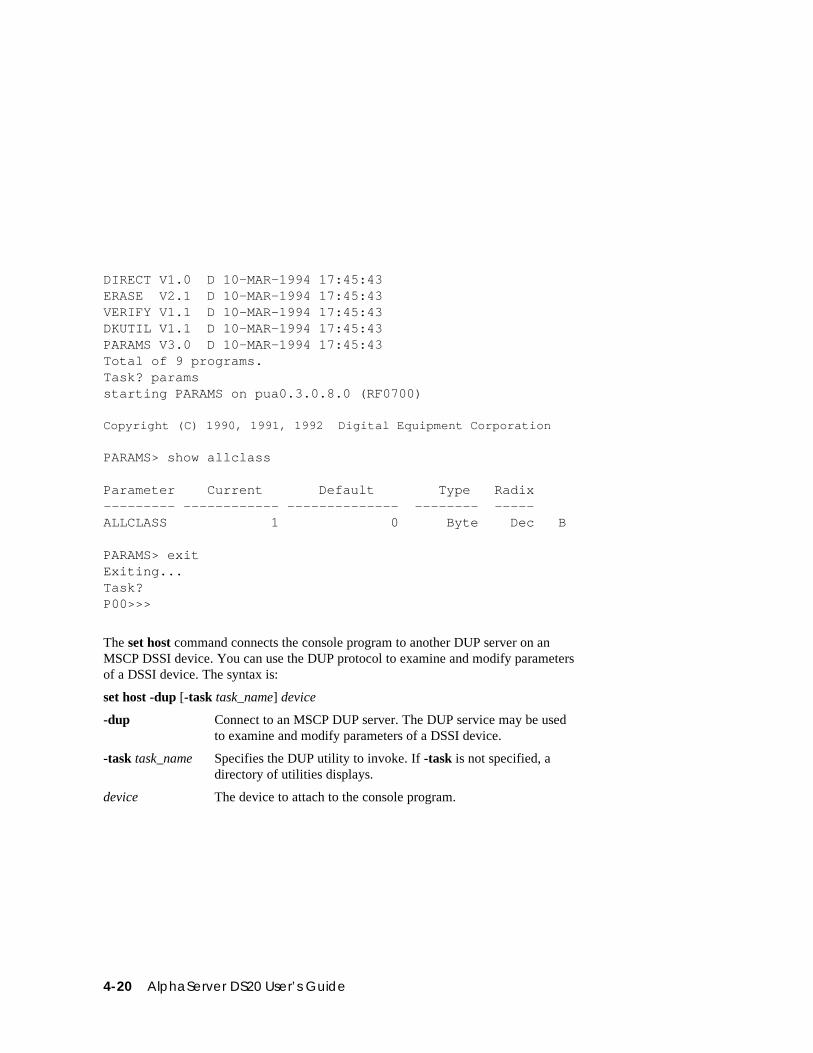
4-20 AlphaServer DS20 User’s Guide
DIRECT V1.0 D 10-MAR-1994 17:45:43ERASE V2.1 D 10-MAR-1994 17:45:43VERIFY V1.1 D 10-MAR-1994 17:45:43DKUTIL V1.1 D 10-MAR-1994 17:45:43PARAMS V3.0 D 10-MAR-1994 17:45:43Total of 9 programs.Task? paramsstarting PARAMS on pua0.3.0.8.0 (RF0700)
Copyright (C) 1990, 1991, 1992 Digital Equipment Corporation
PARAMS> show allclass
Parameter Current Default Type Radix--------- ------------ -------------- -------- -----ALLCLASS 1 0 Byte Dec B
PARAMS> exitExiting...Task?P00>>>
The set host command connects the console program to another DUP server on anMSCP DSSI device. You can use the DUP protocol to examine and modify parametersof a DSSI device. The syntax is:
set host -dup [-task task_name] device
-dup Connect to an MSCP DUP server. The DUP service may be usedto examine and modify parameters of a DSSI device.
-task task_name Specifies the DUP utility to invoke. If -task is not specified, adirectory of utilities displays.
device The device to attach to the console program.
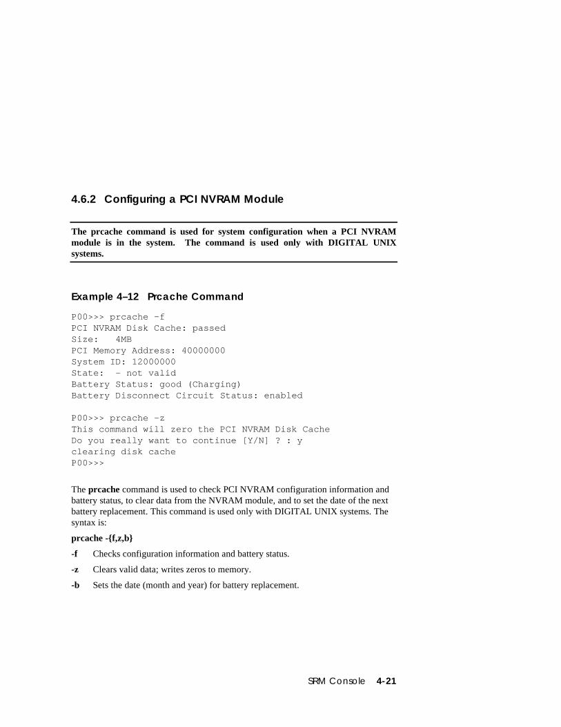
SRM Console 4-21
4.6.2 Configuring a PCI NVRAM Module
The prcache command is used for system configuration when a PCI NVRAMmodule is in the system. The command is used only with DIGITAL UNIXsystems.
Example 4–12 Prcache Command
P00>>> prcache -fPCI NVRAM Disk Cache: passedSize: 4MBPCI Memory Address: 40000000System ID: 12000000State: - not validBattery Status: good (Charging)Battery Disconnect Circuit Status: enabled
P00>>> prcache -zThis command will zero the PCI NVRAM Disk CacheDo you really want to continue [Y/N] ? : yclearing disk cacheP00>>>
The prcache command is used to check PCI NVRAM configuration information andbattery status, to clear data from the NVRAM module, and to set the date of the nextbattery replacement. This command is used only with DIGITAL UNIX systems. Thesyntax is:
prcache -{f,z,b}
-f Checks configuration information and battery status.
-z Clears valid data; writes zeros to memory.
-b Sets the date (month and year) for battery replacement.
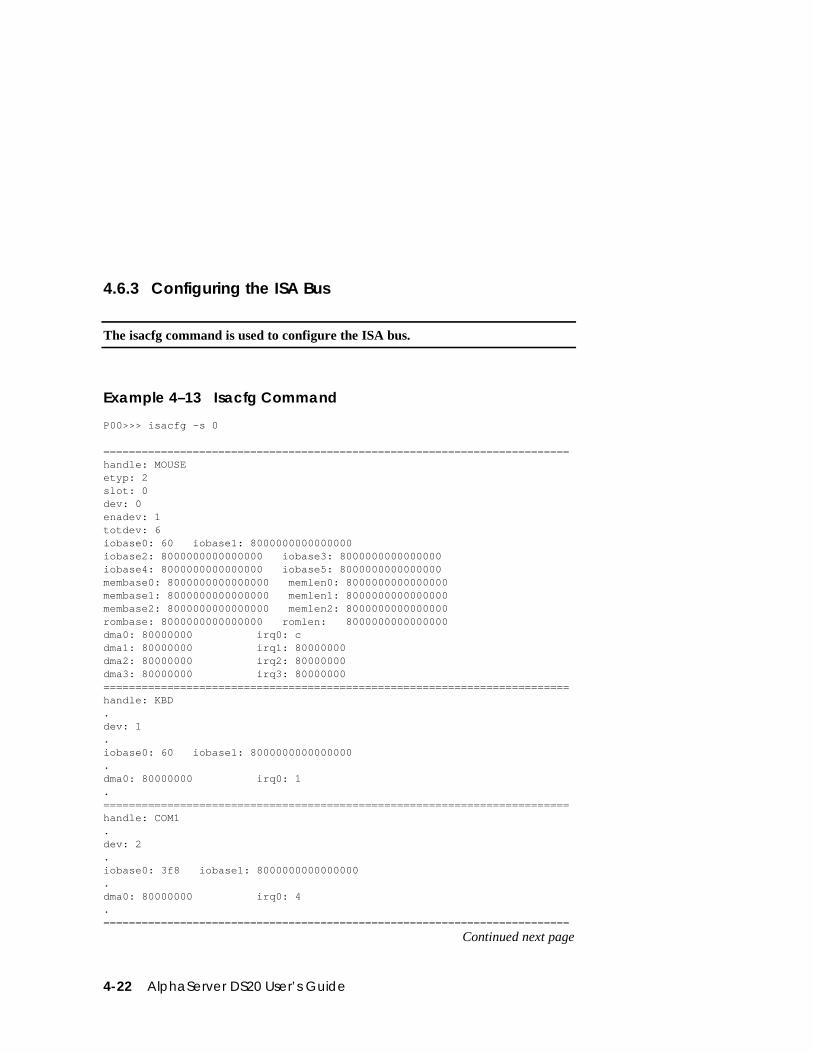
4-22 AlphaServer DS20 User’s Guide
4.6.3 Configuring the ISA Bus
The isacfg command is used to configure the ISA bus.
Example 4–13 Isacfg Command
P00>>> isacfg -s 0
=========================================================================handle: MOUSEetyp: 2slot: 0dev: 0enadev: 1totdev: 6iobase0: 60 iobase1: 8000000000000000iobase2: 8000000000000000 iobase3: 8000000000000000iobase4: 8000000000000000 iobase5: 8000000000000000membase0: 8000000000000000 memlen0: 8000000000000000membase1: 8000000000000000 memlen1: 8000000000000000membase2: 8000000000000000 memlen2: 8000000000000000rombase: 8000000000000000 romlen: 8000000000000000dma0: 80000000 irq0: cdma1: 80000000 irq1: 80000000dma2: 80000000 irq2: 80000000dma3: 80000000 irq3: 80000000=========================================================================handle: KBD.dev: 1.iobase0: 60 iobase1: 8000000000000000.dma0: 80000000 irq0: 1.=========================================================================handle: COM1.dev: 2.iobase0: 3f8 iobase1: 8000000000000000.dma0: 80000000 irq0: 4.=========================================================================
Continued next page
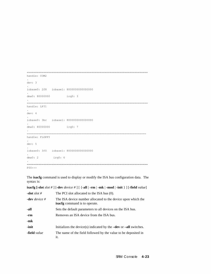
SRM Console 4-23
=========================================================================handle: COM2.dev: 3.iobase0: 2f8 iobase1: 8000000000000000.dma0: 80000000 irq0: 3.=========================================================================handle: LPT1.dev: 4.iobase0: 3bc iobase1: 8000000000000000.dma0: 80000000 irq0: 7.========================================================================handle: FLOPPY.dev: 5.iobase0: 3f0 iobase1: 8000000000000000.dma0: 2 irq0: 6.=========================================================================P00>>>
The isacfg command is used to display or modify the ISA bus configuration data. Thesyntax is:
isacfg [-slot slot # ] [-dev device # ] [ {-all | -rm | -mk | -mod | -init } ] [-field value]
-slot slot # The PCI slot allocated to the ISA bus (0).
-dev device # The ISA device number allocated to the device upon which theisacfg command is to operate.
-all Sets the default parameters to all devices on the ISA bus.
-rm Removes an ISA device from the ISA bus.
-mk
-init Initializes the device(s) indicated by the –dev or –all switches.
-field value The name of the field followed by the value to be deposited init.
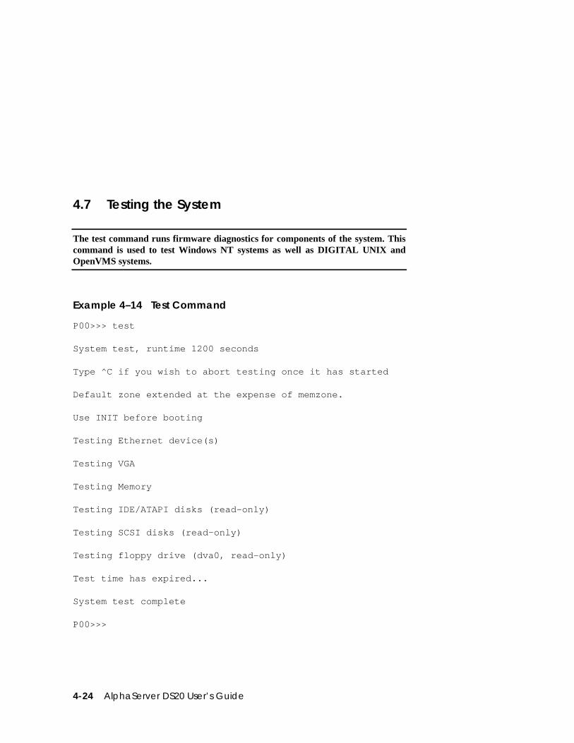
4-24 AlphaServer DS20 User’s Guide
4.7 Testing the System
The test command runs firmware diagnostics for components of the system. Thiscommand is used to test Windows NT systems as well as DIGITAL UNIX andOpenVMS systems.
Example 4–14 Test Command
P00>>> test
System test, runtime 1200 seconds
Type ^C if you wish to abort testing once it has started
Default zone extended at the expense of memzone.
Use INIT before booting
Testing Ethernet device(s)
Testing VGA
Testing Memory
Testing IDE/ATAPI disks (read-only)
Testing SCSI disks (read-only)
Testing floppy drive (dva0, read-only)
Test time has expired...
System test complete
P00>>>
SRM Console 4-25
The test command runs console-based exercisers for devices in the system.
Testing can be aborted by Ctrl/C.
NOTE: If you are running the Microsoft Windows NT operating system, switch fromAlphaBIOS to the SRM console in order to enter the test command. SelectDIGITAL UNIX Console (SRM) or OpenVMS Console (SRM) from theAdvanced CMOS Setup of the AlphaBIOS console screen, save the setting bypressing the F10 key, and then reset the system. Or, from the AlphaBIOSconsole, press the Reset button, wait 5 seconds, then press the Halt button.
The syntax is:
test [-t time] [-q] [option]
-t time Specifies the run time in seconds. The default for system test is 1200seconds (20 minutes).
-q Disables the display of status messages as exerciser processes arestarted and stopped during testing. Sets the environment variabled_verbose to zero.
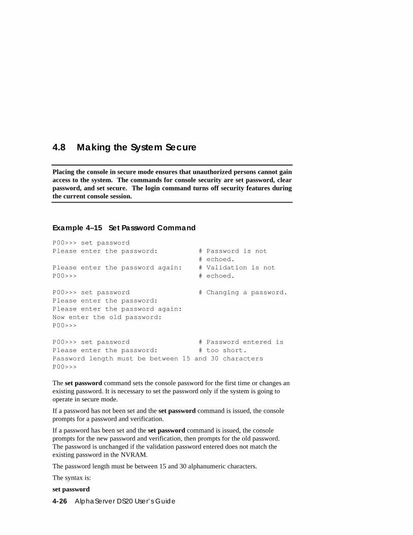
4-26 AlphaServer DS20 User’s Guide
4.8 Making the System Secure
Placing the console in secure mode ensures that unauthorized persons cannot gainaccess to the system. The commands for console security are set password, clearpassword, and set secure. The login command turns off security features duringthe current console session.
Example 4–15 Set Password Command
P00>>> set passwordPlease enter the password: # Password is not # echoed.Please enter the password again: # Validation is notP00>>> # echoed.
P00>>> set password # Changing a password.Please enter the password:Please enter the password again:Now enter the old password:P00>>>
P00>>> set password # Password entered isPlease enter the password: # too short.Password length must be between 15 and 30 charactersP00>>>
The set password command sets the console password for the first time or changes anexisting password. It is necessary to set the password only if the system is going tooperate in secure mode.
If a password has not been set and the set password command is issued, the consoleprompts for a password and verification.
If a password has been set and the set password command is issued, the consoleprompts for the new password and verification, then prompts for the old password.The password is unchanged if the validation password entered does not match theexisting password in the NVRAM.
The password length must be between 15 and 30 alphanumeric characters.
The syntax is:
set password
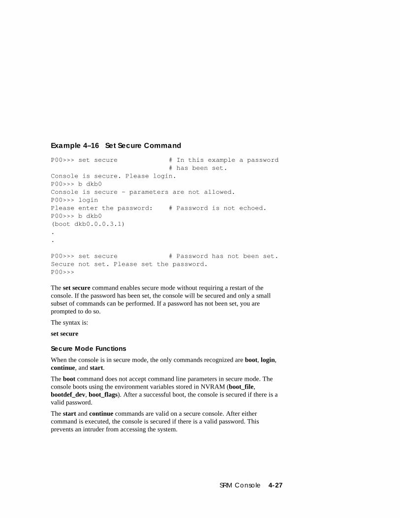
SRM Console 4-27
Example 4–16 Set Secure Command
P00>>> set secure # In this example a password # has been set.Console is secure. Please login.P00>>> b dkb0Console is secure - parameters are not allowed.P00>>> loginPlease enter the password: # Password is not echoed.P00>>> b dkb0(boot dkb0.0.0.3.1)..
P00>>> set secure # Password has not been set.Secure not set. Please set the password.P00>>>
The set secure command enables secure mode without requiring a restart of theconsole. If the password has been set, the console will be secured and only a smallsubset of commands can be performed. If a password has not been set, you areprompted to do so.
The syntax is:
set secure
Secure Mode Functions
When the console is in secure mode, the only commands recognized are boot, login,continue, and start.
The boot command does not accept command line parameters in secure mode. Theconsole boots using the environment variables stored in NVRAM (boot_file,bootdef_dev, boot_flags). After a successful boot, the console is secured if there is avalid password.
The start and continue commands are valid on a secure console. After eithercommand is executed, the console is secured if there is a valid password. Thisprevents an intruder from accessing the system.
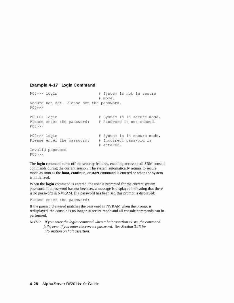
4-28 AlphaServer DS20 User’s Guide
Example 4–17 Login Command
P00>>> login # System is not in secure # mode.Secure not set. Please set the password.P00>>>
P00>>> login # System is in secure mode.Please enter the password: # Password is not echoed.P00>>>
P00>>> login # System is in secure mode.Please enter the password: # Incorrect password is # entered.Invalid passwordP00>>>
The login command turns off the security features, enabling access to all SRM consolecommands during the current session. The system automatically returns to securemode as soon as the boot, continue, or start command is entered or when the systemis initialized.
When the login command is entered, the user is prompted for the current systempassword. If a password has not been set, a message is displayed indicating that thereis no password in NVRAM. If a password has been set, this prompt is displayed:
Please enter the password:
If the password entered matches the password in NVRAM when the prompt isredisplayed, the console is no longer in secure mode and all console commands can beperformed.
NOTE: If you enter the login command when a halt assertion exists, the commandfails, even if you enter the correct password. See Section 3.13 forinformation on halt assertion.
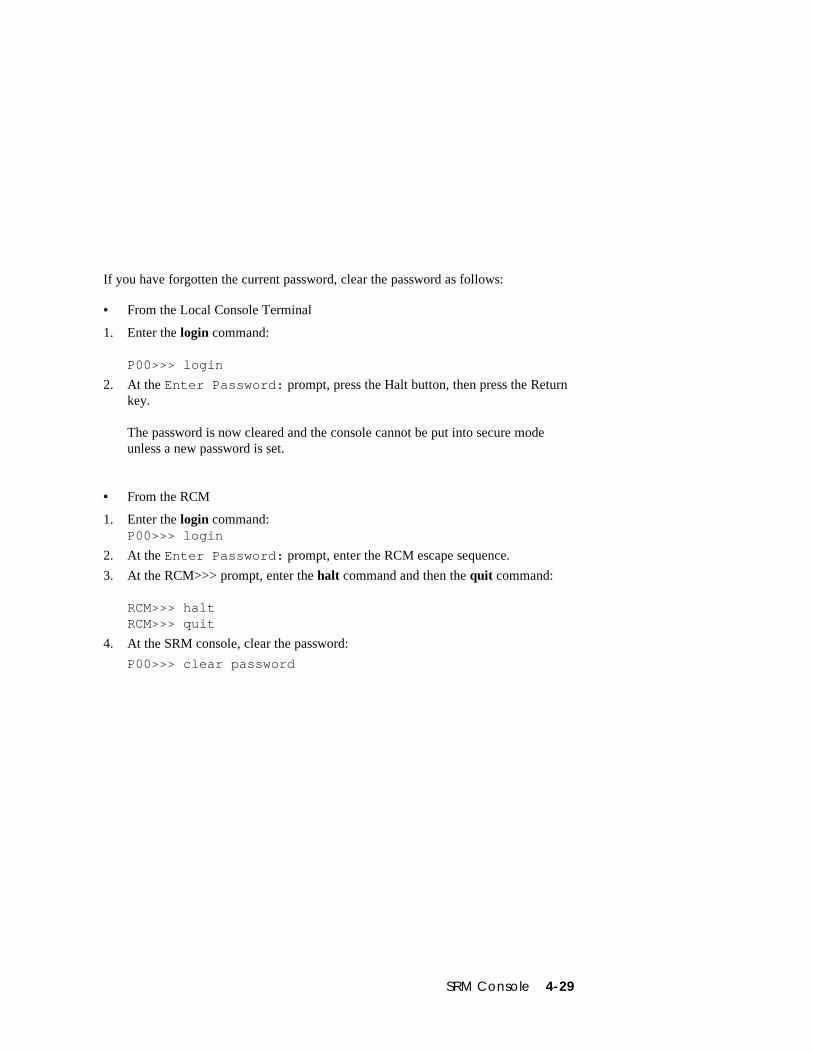
SRM Console 4-29
If you have forgotten the current password, clear the password as follows:
• From the Local Console Terminal
1. Enter the login command:
P00>>> login
2. At the Enter Password: prompt, press the Halt button, then press the Returnkey.
The password is now cleared and the console cannot be put into secure modeunless a new password is set.
• From the RCM
1. Enter the login command:P00>>> login
2. At the Enter Password: prompt, enter the RCM escape sequence.
3. At the RCM>>> prompt, enter the halt command and then the quit command:
RCM>>> haltRCM>>> quit
4. At the SRM console, clear the password:
P00>>> clear password
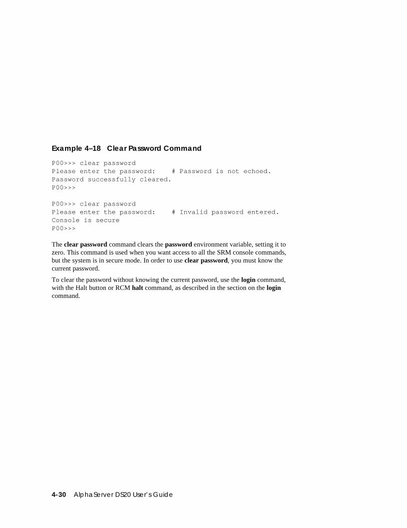
4-30 AlphaServer DS20 User’s Guide
Example 4–18 Clear Password Command
P00>>> clear passwordPlease enter the password: # Password is not echoed.Password successfully cleared.P00>>>
P00>>> clear passwordPlease enter the password: # Invalid password entered.Console is secureP00>>>
The clear password command clears the password environment variable, setting it tozero. This command is used when you want access to all the SRM console commands,but the system is in secure mode. In order to use clear password, you must know thecurrent password.
To clear the password without knowing the current password, use the login command,with the Halt button or RCM halt command, as described in the section on the logincommand.
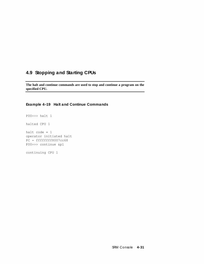
SRM Console 4-31
4.9 Stopping and Starting CPUs
The halt and continue commands are used to stop and continue a program on thespecified CPU.
Example 4–19 Halt and Continue Commands
P00>>> halt 1
halted CPU 1
halt code = 1operator initiated haltPC = ffffffff8007cc68P00>>> continue &p1
continuing CPU 1
4-32 AlphaServer DS20 User’s Guide
halt (or stop)
The halt (or stop) command stops program execution on a secondary CPU that is stillrunning a booted program. The syntax is:
halt (or stop) processor_number
processor_number is the logical CPU number displayed by the show cpu command.
continue
The continue command resumes program execution on the specified processor or onthe primary processor if none is specified. The processor begins executing instructionsat the address that is currently in the program counter (PC). The processor is notinitialized.
The continue command is valid only if you have not disturbed the system state and ifyou halted the system by pressing the Halt button on the control panel or, forOpenVMS systems only, by entering Ctrl/P on the console terminal. The syntax is:
continue [&pn] [address]
&pn Specifies the processor. n is 0 or 1.
address The starting address of the program.
NOTE: Some console commands, for example, boot, can alter the machine state sothat program mode cannot be successfully resumed (unless you include -haltin the boot command). If program mode cannot be resumed, reboot theoperating system.
Other commands that alter machine state are lfu, show device, and test.
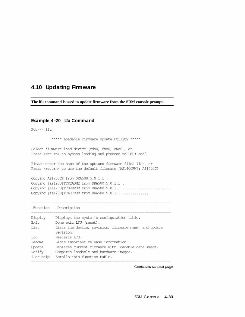
SRM Console 4-33
4.10 Updating Firmware
The lfu command is used to update firmware from the SRM console prompt.
Example 4–20 Lfu Command
P00>>> lfu
***** Loadable Firmware Update Utility *****
Select firmware load device (cda0, dva0, ewa0), orPress <return> to bypass loading and proceed to LFU: cda0
Please enter the name of the options firmware files list, orPress <return> to use the default filename [AS1400FW]: AS1400CP
Copying AS1200CP from DKA500.5.0.1.1 .Copying [as1200]TCREADME from DKA500.5.0.1.1 .Copying [as1200]TCSRMROM from DKA500.5.0.1.1 ........................Copying [as1200]TCARCROM from DKA500.5.0.1.1 .............
--------------------------------------------------------------------- Function Description---------------------------------------------------------------------Display Displays the system’s configuration table.Exit Done exit LFU (reset).List Lists the device, revision, firmware name, and update revision.Lfu Restarts LFU.Readme Lists important release information.Update Replaces current firmware with loadable data image.Verify Compares loadable and hardware images.? or Help Scrolls this function table.---------------------------------------------------------------------
Continued on next page
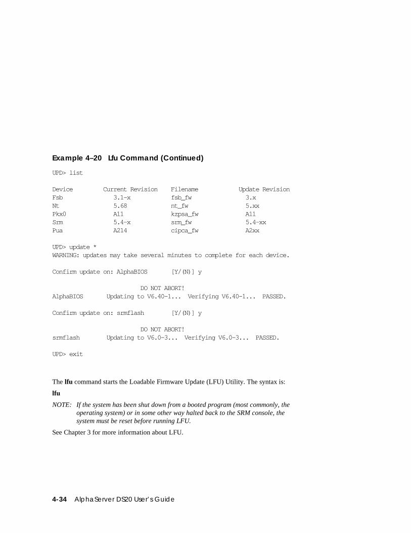
4-34 AlphaServer DS20 User’s Guide
Example 4–20 Lfu Command (Continued)
UPD> list
Device Current Revision Filename Update RevisionFsb 3.1-x fsb_fw 3.xNt 5.68 nt_fw 5.xxPkx0 A11 kzpsa_fw A11Srm 5.4-x srm_fw 5.4-xxPua A214 cipca_fw A2xx
UPD> update *WARNING: updates may take several minutes to complete for each device.
Confirm update on: AlphaBIOS [Y/(N)] y
DO NOT ABORT!AlphaBIOS Updating to V6.40-1... Verifying V6.40-1... PASSED.
Confirm update on: srmflash [Y/(N)] y
DO NOT ABORT!srmflash Updating to V6.0-3... Verifying V6.0-3... PASSED.
UPD> exit
The lfu command starts the Loadable Firmware Update (LFU) Utility. The syntax is:
lfu
NOTE: If the system has been shut down from a booted program (most commonly, theoperating system) or in some other way halted back to the SRM console, thesystem must be reset before running LFU.
See Chapter 3 for more information about LFU.
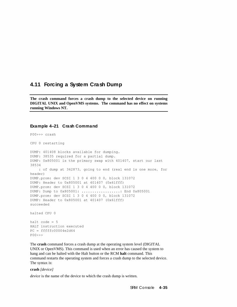
SRM Console 4-35
4.11 Forcing a System Crash Dump
The crash command forces a crash dump to the selected device on runningDIGITAL UNIX and OpenVMS systems. The command has no effect on systemsrunning Windows NT.
Example 4–21 Crash Command
P00>>> crash
CPU 0 restarting
DUMP: 401408 blocks available for dumping.DUMP: 38535 required for a partial dump.DUMP: 0x805001 is the primary swap with 401407, start our last38534 : of dump at 362873, going to end (real end is one more, forheader)DUMP.prom: dev SCSI 1 3 0 4 400 0 0, block 131072DUMP: Header to 0x805001 at 401407 (0x61fff)DUMP.prom: dev SCSI 1 3 0 4 400 0 0, block 131072DUMP: Dump to 0x805001: ..................: End 0x805001DUMP.prom: dev SCSI 1 3 0 4 400 0 0, block 131072DUMP: Header to 0x805001 at 401407 (0x61fff)succeeded
halted CPU 0
halt code = 5HALT instruction executedPC = fffffc00004e2d64P00>>>
The crash command forces a crash dump at the operating system level (DIGITALUNIX or OpenVMS). This command is used when an error has caused the system tohang and can be halted with the Halt button or the RCM halt command. Thiscommand restarts the operating system and forces a crash dump to the selected device.The syntax is:
crash [device]
device is the name of the device to which the crash dump is written.
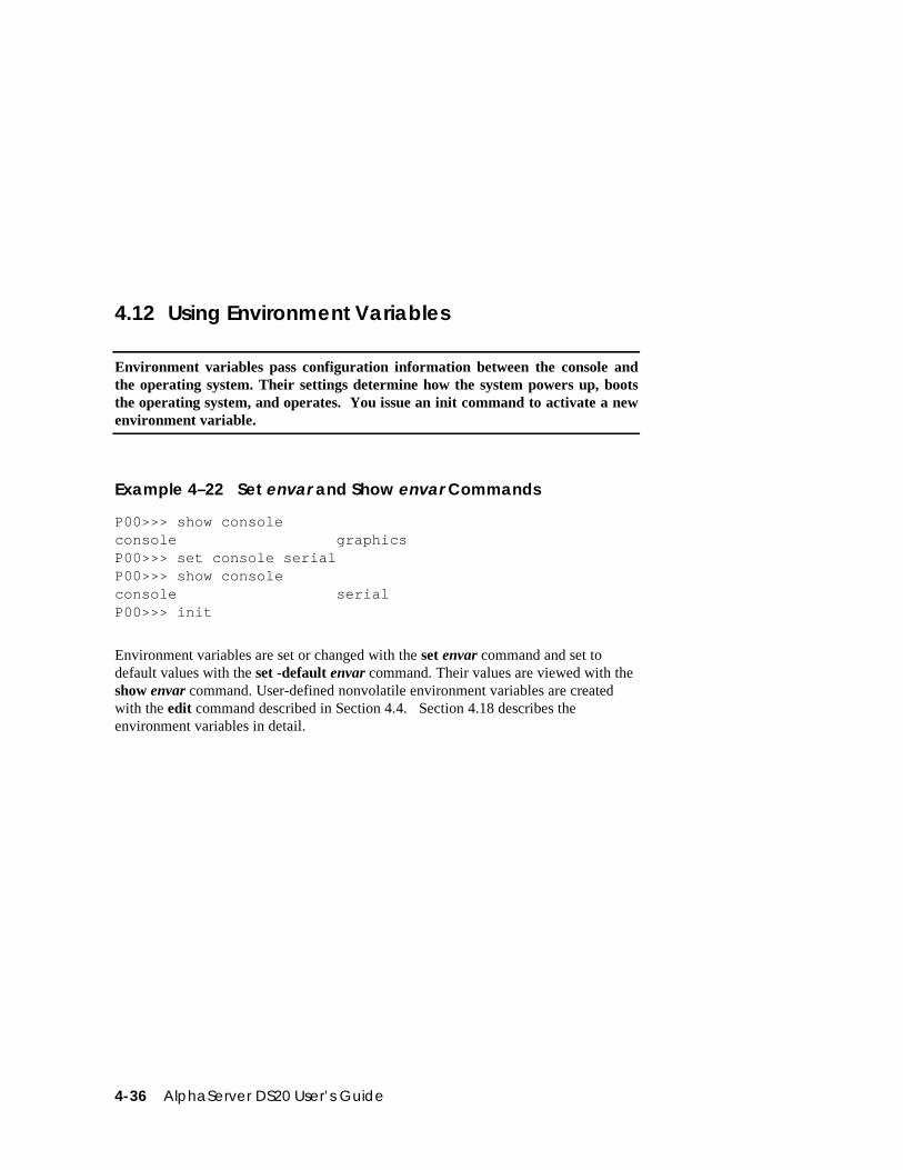
4-36 AlphaServer DS20 User’s Guide
4.12 Using Environment Variables
Environment variables pass configuration information between the console andthe operating system. Their settings determine how the system powers up, bootsthe operating system, and operates. You issue an init command to activate a newenvironment variable.
Example 4–22 Set envar and Show envar Commands
P00>>> show consoleconsole graphicsP00>>> set console serialP00>>> show consoleconsole serialP00>>> init
Environment variables are set or changed with the set envar command and set todefault values with the set -default envar command. Their values are viewed with theshow envar command. User-defined nonvolatile environment variables are createdwith the edit command described in Section 4.4. Section 4.18 describes theenvironment variables in detail.
SRM Console 4-37
set envar
The set command sets or modifies the value of an environment variable. It can also beused to create a new environment variable if the name used is unique. Environmentvariables are used to pass configuration information between the console and theoperating system. The setting of these variables determines how the system powers up,boots the operating system, and operates. The syntax is:
set [-default] envar value
-default Restores an environment variable to its default setting.
envar The name of the environment variable to be modified.
value The new value of the environment variable.
Whenever you modify the value of any of the following environment variables, thenew value takes effect only after you reset the system by pressing the Reset button orissuing the initialize command:
consolekbd_hardware_typelanguageocp_textos_type
show envar
The show envar command displays the current value (or setting) of an environmentvariable. The syntax is:
show envar
envar The name of the environment variable to be displayed. The wildcard *displays all environment variables.
4-38 AlphaServer DS20 User’s Guide
Example 4–23 Creating a User-Defined Environment Variable
P00>>> edit nvramediting ‘nvram’0 bytes read in*10 set mopv3_boot 1*exit17 bytes written out to nvram
P00>>>
In Example 4–23 the nvram script is edited so that an environment variable called“mop3_boot” is created and set to 1 on each power-up. By default, MOP boots sendfour MOP V4 requests before defaulting to MOP V3. This user-created environmentvariable forces the SRM console to bypass MOP V4 requests. This speeds up MOPbooting on networks with MOP V3 software.
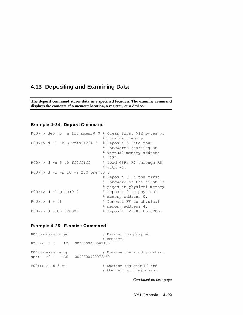
SRM Console 4-39
4.13 Depositing and Examining Data
The deposit command stores data in a specified location. The examine commanddisplays the contents of a memory location, a register, or a device.
Example 4–24 Deposit Command
P00>>> dep -b -n 1ff pmem:0 0 # Clear first 512 bytes of# physical memory.
P00>>> d -l -n 3 vmem:1234 5 # Deposit 5 into four# longwords starting at# virtual memory address# 1234.
P00>>> d -n 8 r0 ffffffff # Load GPRs R0 through R8# with -1.
P00>>> d -l -n 10 -s 200 pmem:0 8# Deposit 8 in the first# longword of the first 17# pages in physical memory.
P00>>> d -l pmem:0 0 # Deposit 0 to physical# memory address 0.
P00>>> d + ff # Deposit FF to physical# memory address 4.
P00>>> d scbb 820000 # Deposit 820000 to SCBB.
Example 4–25 Examine Command
P00>>> examine pc # Examine the program# counter.
PC psr: 0 ( PC) 0000000000001170
P00>>> examine sp # Examine the stack pointer.gpr: F0 ( R30) 0000000000072A60
P00>>> e -n 6 r4 # Examine register R4 and# the next six registers.
Continued on next page
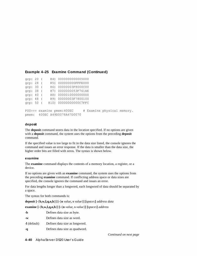
4-40 AlphaServer DS20 User’s Guide
Example 4–25 Examine Command (Continued)
grp: 20 ( R4) 0000000000005000grp: 28 ( R5) 000000000FFFE000grp: 30 ( R6) 00000003F8000C00grp: 38 ( R7) 0000000053F761AEgrp: 40 ( R8) 0000010000000000grp: 48 ( R9) 00000003F7800100grp: 50 ( R10) 00000000000C7FFC
P00>>> examine pmem:400EC # Examine physical memory.pmem: 400EC A49D0078A47D0070
deposit
The deposit command stores data in the location specified. If no options are givenwith a deposit command, the system uses the options from the preceding depositcommand.
If the specified value is too large to fit in the data size listed, the console ignores thecommand and issues an error response. If the data is smaller than the data size, thehigher order bits are filled with zeros. The syntax is shown below.
examine
The examine command displays the contents of a memory location, a register, or adevice.
If no options are given with an examine command, the system uses the options fromthe preceding examine command. If conflicting address space or data sizes arespecified, the console ignores the command and issues an error.
For data lengths longer than a longword, each longword of data should be separated bya space.
The syntax for both commands is:
deposit [-{b,w,l,q,o,h}] [-{n value, s value}] [space:] address data
examine [-{b,w,l,q,o,h}] [-{n value, s value}] [space:] address
-b Defines data size as byte.
-w Defines data size as word.
-l (default) Defines data size as longword.
-q Defines data size as quadword.
Continued on next page
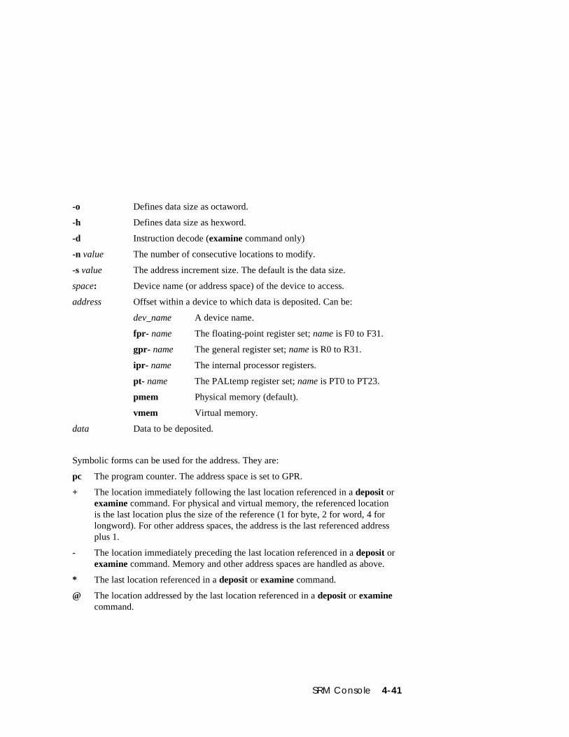
SRM Console 4-41
-o Defines data size as octaword.
-h Defines data size as hexword.
-d Instruction decode (examine command only)
-n value The number of consecutive locations to modify.
-s value The address increment size. The default is the data size.
space: Device name (or address space) of the device to access.
address Offset within a device to which data is deposited. Can be:
dev_name A device name.
fpr- name The floating-point register set; name is F0 to F31.
gpr- name The general register set; name is R0 to R31.
ipr- name The internal processor registers.
pt- name The PALtemp register set; name is PT0 to PT23.
pmem Physical memory (default).
vmem Virtual memory.
data Data to be deposited.
Symbolic forms can be used for the address. They are:
pc The program counter. The address space is set to GPR.
+ The location immediately following the last location referenced in a deposit orexamine command. For physical and virtual memory, the referenced locationis the last location plus the size of the reference (1 for byte, 2 for word, 4 forlongword). For other address spaces, the address is the last referenced addressplus 1.
- The location immediately preceding the last location referenced in a deposit orexamine command. Memory and other address spaces are handled as above.
* The last location referenced in a deposit or examine command.
@ The location addressed by the last location referenced in a deposit or examinecommand.
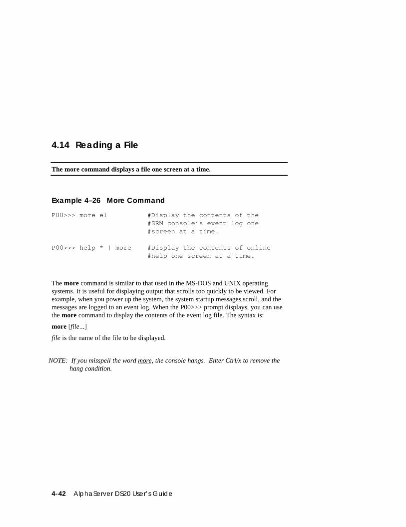
4-42 AlphaServer DS20 User’s Guide
4.14 Reading a File
The more command displays a file one screen at a time.
Example 4–26 More Command
P00>>> more el #Display the contents of the#SRM console’s event log one#screen at a time.
P00>>> help * | more #Display the contents of online#help one screen at a time.
The more command is similar to that used in the MS-DOS and UNIX operatingsystems. It is useful for displaying output that scrolls too quickly to be viewed. Forexample, when you power up the system, the system startup messages scroll, and themessages are logged to an event log. When the P00>>> prompt displays, you can usethe more command to display the contents of the event log file. The syntax is:
more [file...]
file is the name of the file to be displayed.
NOTE: If you misspell the word more, the console hangs. Enter Ctrl/x to remove thehang condition.
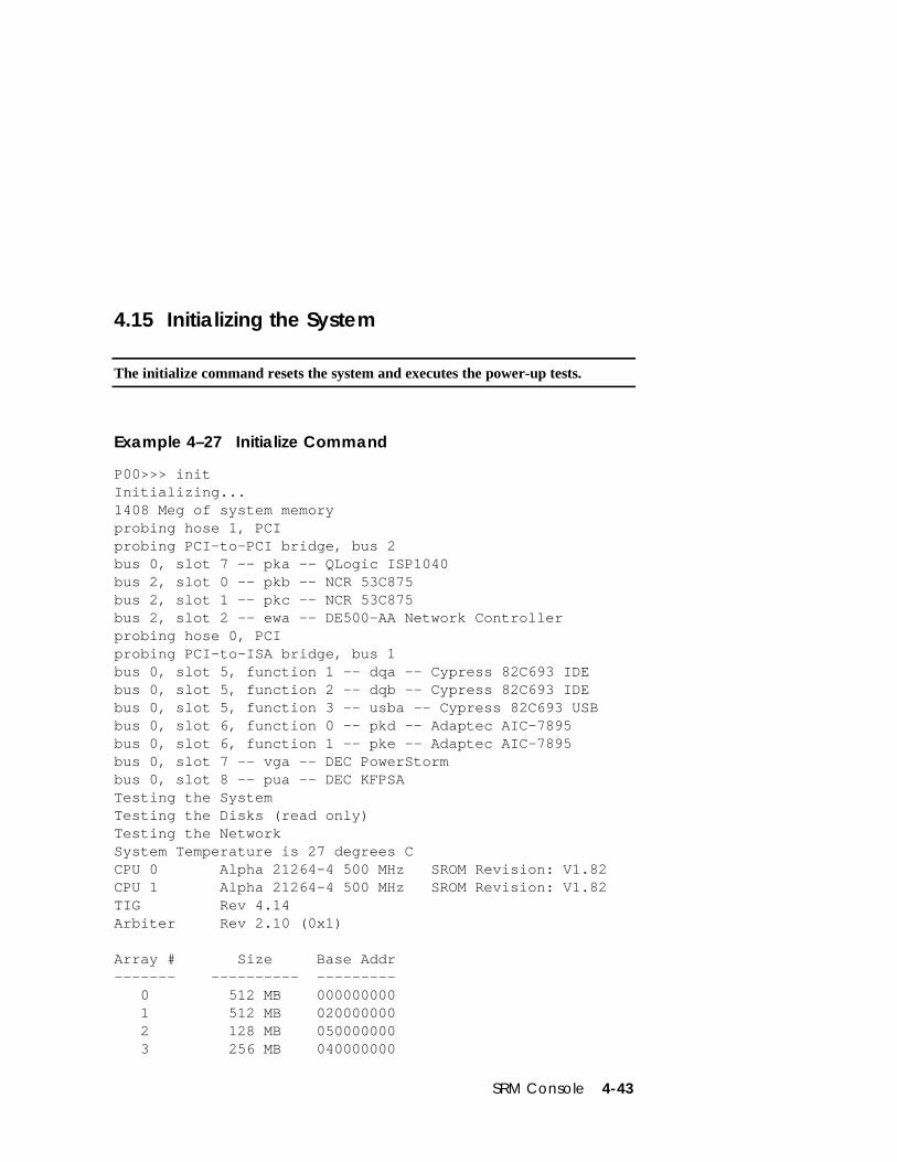
SRM Console 4-43
4.15 Initializing the System
The initialize command resets the system and executes the power-up tests.
Example 4–27 Initialize Command
P00>>> initInitializing...1408 Meg of system memoryprobing hose 1, PCIprobing PCI-to-PCI bridge, bus 2bus 0, slot 7 -- pka -- QLogic ISP1040bus 2, slot 0 -- pkb -- NCR 53C875bus 2, slot 1 -- pkc -- NCR 53C875bus 2, slot 2 -- ewa -- DE500-AA Network Controllerprobing hose 0, PCIprobing PCI-to-ISA bridge, bus 1bus 0, slot 5, function 1 -- dqa -- Cypress 82C693 IDEbus 0, slot 5, function 2 -- dqb -- Cypress 82C693 IDEbus 0, slot 5, function 3 -- usba -- Cypress 82C693 USBbus 0, slot 6, function 0 -- pkd -- Adaptec AIC-7895bus 0, slot 6, function 1 -- pke -- Adaptec AIC-7895bus 0, slot 7 -- vga -- DEC PowerStormbus 0, slot 8 -- pua -- DEC KFPSATesting the SystemTesting the Disks (read only)Testing the NetworkSystem Temperature is 27 degrees CCPU 0 Alpha 21264-4 500 MHz SROM Revision: V1.82CPU 1 Alpha 21264-4 500 MHz SROM Revision: V1.82TIG Rev 4.14Arbiter Rev 2.10 (0x1)
Array # Size Base Addr------- ---------- --------- 0 512 MB 000000000 1 512 MB 020000000 2 128 MB 050000000 3 256 MB 040000000
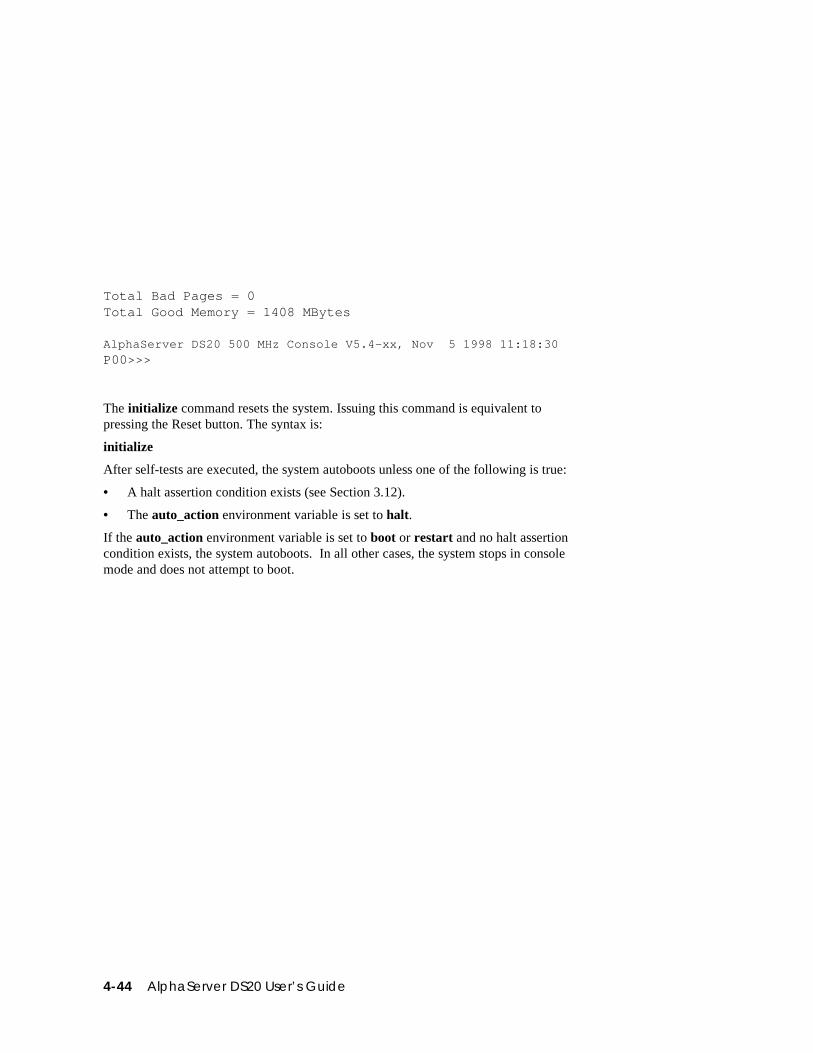
4-44 AlphaServer DS20 User’s Guide
Total Bad Pages = 0Total Good Memory = 1408 MBytes
AlphaServer DS20 500 MHz Console V5.4-xx, Nov 5 1998 11:18:30P00>>>
The initialize command resets the system. Issuing this command is equivalent topressing the Reset button. The syntax is:
initialize
After self-tests are executed, the system autoboots unless one of the following is true:
• A halt assertion condition exists (see Section 3.12).
• The auto_action environment variable is set to halt.
If the auto_action environment variable is set to boot or restart and no halt assertioncondition exists, the system autoboots. In all other cases, the system stops in consolemode and does not attempt to boot.
SRM Console 4-45
4.16 Finding Help
The help command displays basic information about a command.
Example 4–28 Help Command
P00>>> help setNAME
setFUNCTION
Set an option or modify the value of an environmentvariable.
SYNOPSISset <option> <value> or <envar> [-] <value>
where<option>={host,mode}where<envar>={auto_action,bootdef_dev,boot_osflags,...}[-default]
The help command displays basic information about the use of console commandswhen the system is in console mode. The syntax is:
help [command . . . ]
command . . . Command or topic for which help is requested. The options are:
none Displays the complete list of commandsfor which you can receive help.
command_name Displays information about the consolecommand.
argument_string(such as “sh”)
Displays information about all commandsthat begin with that string.
4-46 AlphaServer DS20 User’s Guide
4.17 Switching from SRM to AlphaBIOS Console
It is necessary to switch to the AlphaBIOS console to run configuration utilities.To switch from SRM to AlphaBIOS, issue the alphabios command.
Example 4–29 Switching to the AlphaBIOS Console
P00>>> alphabios
The alphabios command loads and starts the AlphaBIOS console. This is necessaryfor running AlphaBIOS-based utilities (such as the RAID configuration utility). Thesyntax is:
alphabios
To return to the SRM console, do one of the following:
• If the os_type environment variable is set to unix or openvms, reset the systemby pressing the Reset button.
• If the os_type environment variable is set to nt, select DIGITAL UNIX console(SRM) or OpenVMS console (SRM) from the Advanced CMOS Setup screen,save the setting by pressing key F10 and then reset the system. Alternatively,press the Reset button, wait 5 seconds, and then press the Halt button.
To switch permanently to the AlphaBIOS console (that is, if the permanent operatingsystem is changed to Windows NT), do the following:
1. Set the SRM os_type environment variable to nt.
2. Set the SRM console environment variable to graphics.
3. Reset the system with the initialize command, the Reset button, or by powercycling.
SRM Console 4-47
4.18 Environment Variable Summary
Environment variables pass configuration information between the console andthe operating system. Their settings determine how the system powers up, bootsthe operating system, and operates. Environment variables are set or changedwith the set envar command and returned to their default values with the clearenvar command. Their values are viewed with the show envar command.
Table 4-6 lists the environment variables. Detailed descriptions follow. Theenvironment variables are specific to the SRM console.
Table 4-6 Environment Variable Summary
EnvironmentVariable Function
auto_action Specifies the console’s action at power-up, a failure, or areset.
bootdef_dev Specifies the default boot device string.
boot_osflags Specifies the default operating system boot flags.
com*_baud Changes the default baud rate of the COM1 or COM2 serialport.
console Specifies the device on which power-up output is displayed(serial terminal or graphics monitor).
cpu_enabled Enables or disables a specific secondary CPU.
ew*0_mode Specifies the connection type of the default Ethernetcontroller.
ew*0_protocols Specifies network protocols for booting over the Ethernetcontroller.
kbd_hardware_type
Specifies the default console keyboard type.
language Specifies the console keyboard layout.
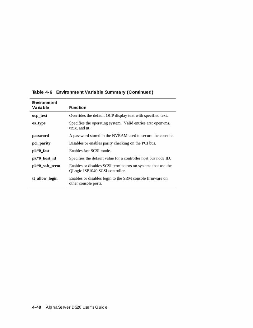
4-48 AlphaServer DS20 User’s Guide
Table 4-6 Environment Variable Summary (Continued)
EnvironmentVariable Function
ocp_text Overrides the default OCP display text with specified text.
os_type Specifies the operating system. Valid entries are: openvms,unix, and nt.
password A password stored in the NVRAM used to secure the console.
pci_parity Disables or enables parity checking on the PCI bus.
pk*0_fast Enables fast SCSI mode.
pk*0_host_id Specifies the default value for a controller host bus node ID.
pk*0_soft_term Enables or disables SCSI terminators on systems that use theQLogic ISP1040 SCSI controller.
tt_allow_login Enables or disables login to the SRM console firmware onother console ports.
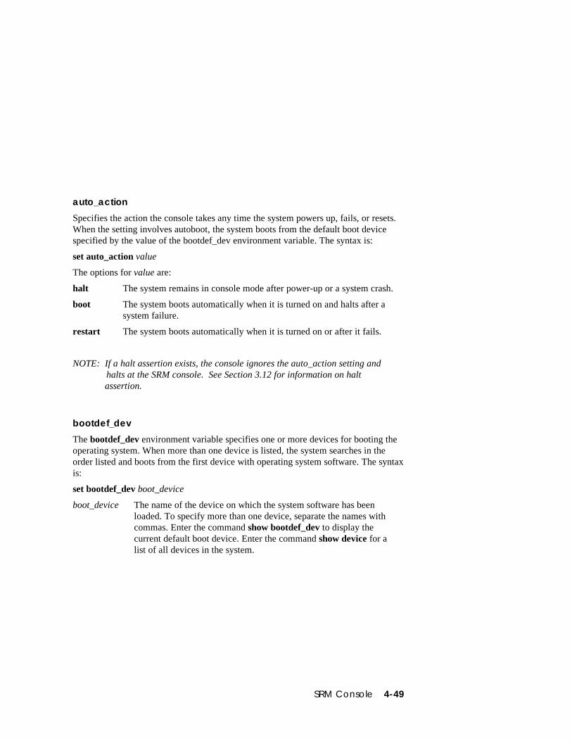
SRM Console 4-49
auto_action
Specifies the action the console takes any time the system powers up, fails, or resets.When the setting involves autoboot, the system boots from the default boot devicespecified by the value of the bootdef_dev environment variable. The syntax is:
set auto_action value
The options for value are:
halt The system remains in console mode after power-up or a system crash.
boot The system boots automatically when it is turned on and halts after asystem failure.
restart The system boots automatically when it is turned on or after it fails.
NOTE: If a halt assertion exists, the console ignores the auto_action setting and halts at the SRM console. See Section 3.12 for information on halt
assertion.
bootdef_dev
The bootdef_dev environment variable specifies one or more devices for booting theoperating system. When more than one device is listed, the system searches in theorder listed and boots from the first device with operating system software. The syntaxis:
set bootdef_dev boot_device
boot_device The name of the device on which the system software has beenloaded. To specify more than one device, separate the names withcommas. Enter the command show bootdef_dev to display thecurrent default boot device. Enter the command show device for alist of all devices in the system.
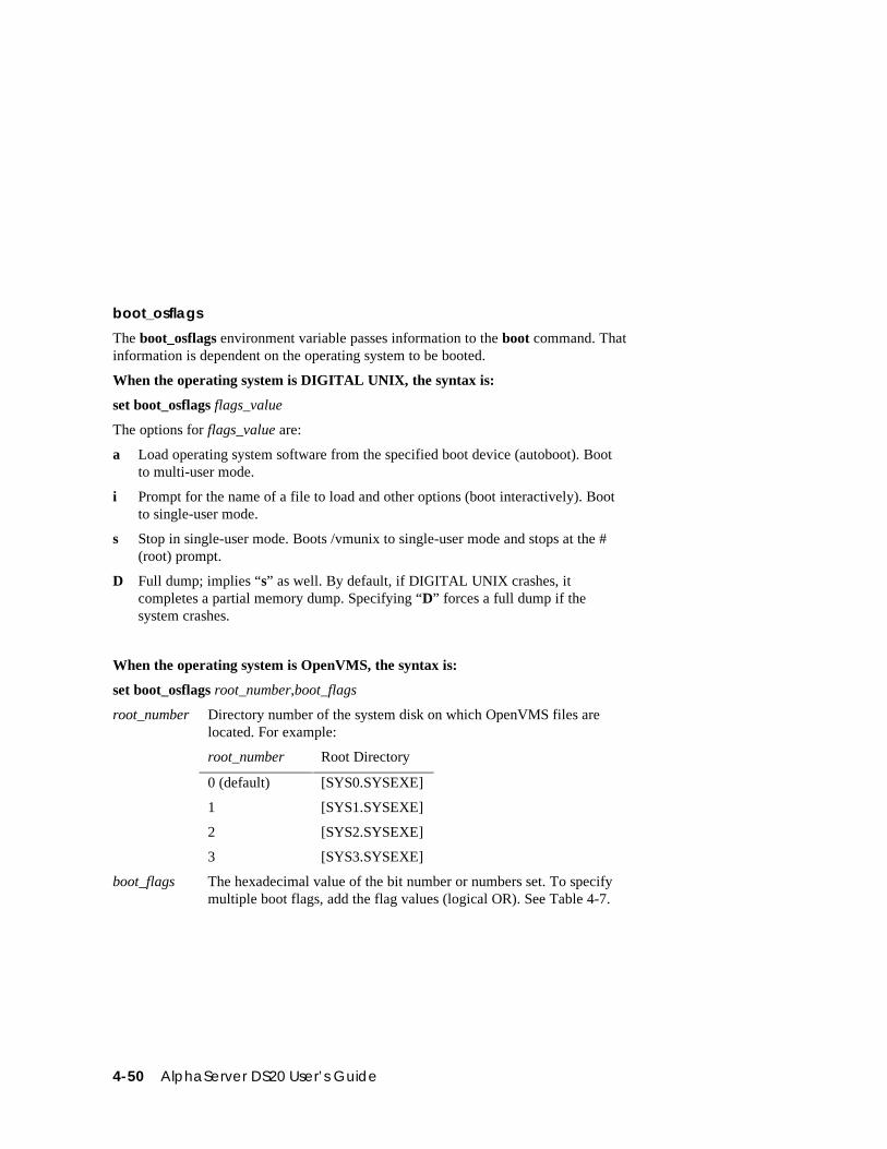
4-50 AlphaServer DS20 User’s Guide
boot_osflags
The boot_osflags environment variable passes information to the boot command. Thatinformation is dependent on the operating system to be booted.
When the operating system is DIGITAL UNIX, the syntax is:
set boot_osflags flags_value
The options for flags_value are:
a Load operating system software from the specified boot device (autoboot). Bootto multi-user mode.
i Prompt for the name of a file to load and other options (boot interactively). Bootto single-user mode.
s Stop in single-user mode. Boots /vmunix to single-user mode and stops at the #(root) prompt.
D Full dump; implies “s” as well. By default, if DIGITAL UNIX crashes, itcompletes a partial memory dump. Specifying “D” forces a full dump if thesystem crashes.
When the operating system is OpenVMS, the syntax is:
set boot_osflags root_number,boot_flags
root_number Directory number of the system disk on which OpenVMS files arelocated. For example:
root_number Root Directory
0 (default) [SYS0.SYSEXE]
1 [SYS1.SYSEXE]
2 [SYS2.SYSEXE]
3 [SYS3.SYSEXE]
boot_flags The hexadecimal value of the bit number or numbers set. To specifymultiple boot flags, add the flag values (logical OR). See Table 4-7.
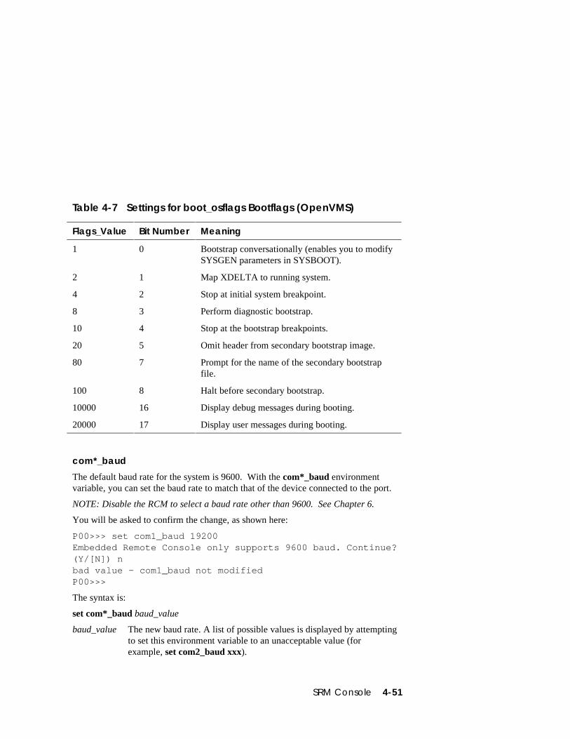
SRM Console 4-51
Table 4-7 Settings for boot_osflags Bootflags (OpenVMS)
Flags_Value Bit Number Meaning
1 0 Bootstrap conversationally (enables you to modifySYSGEN parameters in SYSBOOT).
2 1 Map XDELTA to running system.
4 2 Stop at initial system breakpoint.
8 3 Perform diagnostic bootstrap.
10 4 Stop at the bootstrap breakpoints.
20 5 Omit header from secondary bootstrap image.
80 7 Prompt for the name of the secondary bootstrapfile.
100 8 Halt before secondary bootstrap.
10000 16 Display debug messages during booting.
20000 17 Display user messages during booting.
com*_baud
The default baud rate for the system is 9600. With the com*_baud environmentvariable, you can set the baud rate to match that of the device connected to the port.
NOTE: Disable the RCM to select a baud rate other than 9600. See Chapter 6.
You will be asked to confirm the change, as shown here:
P00>>> set com1_baud 19200Embedded Remote Console only supports 9600 baud. Continue?(Y/[N]) nbad value - com1_baud not modifiedP00>>>
The syntax is:
set com*_baud baud_value
baud_value The new baud rate. A list of possible values is displayed by attemptingto set this environment variable to an unacceptable value (forexample, set com2_baud xxx).
4-52 AlphaServer DS20 User’s Guide
console
The console terminal can be either a graphics monitor or a serial terminal. Theconsole environment variable specifies which is used. The syntax is:
set console output_device
The options for output_device are:
graphics(default)
The console terminal is a graphics monitor or a device connected to theVGA or TGA module.
serial The console terminal is the device connected to the COM1 port.
Whenever you change the value of console, you must reset the system by pressing theReset button or issuing the initialize command.
cpu_enabled
Sets a bit mask that enables or disables specific CPUs on a multiprocessor system.
Disabled CPUs are prevented from running the console or the operating system. Bit 0of the mask corresponds to CPU 0, and bit 1 to CPU 1. A zero in the bit mask preventsthe corresponding CPU from running; a one allows it to run. The bit mask isexpressed as a hexadecimal value.
NOTE: The primary CPU cannot be disabled.
The syntax is:
set cpu_enabled hex_digit
The options for hex_digit are 0 and 1 (hexadecimal).
SRM Console 4-53
ew*0_mode
Sets an Ethernet controller to run an AUI, ThinWire, or twisted-pair Ethernet network.The default is auto-sense. For the fast setting, the device defaults to fast.
The syntax is:
set ew*0_mode value
The options for value are:
aui Device type is AUI.
auto-sense Device type is sensed by the console.
twisted-pair Device type is 10BaseT (twisted pair).
fast duplex,twisted-pair
Device type is duplex 10BaseT
fast Device type is fast SCSI
fast FD Device type is fast full duplex SCSI
BNC Device type is BNC
auto-negotiate DE500-BA
ew*0_protocols
Enables network protocols for booting and other functions. The syntax is:
set ew*0_protocols protocol_value
The options for protocol_value are:
mop (default) Sets the network protocol to mop (Maintenance OperationsProtocol), the setting typically used with the OpenVMS operatingsystem.
bootp Sets the network protocol to bootp, the setting typically used withthe DIGITAL UNIX operating system.
bootp,mop When both are listed, the system attempts to use the mop protocolfirst, regardless of which is listed first. If not successful, it thenattempts the bootp protocol.
4-54 AlphaServer DS20 User’s Guide
kbd_hardware_type
Used only on systems with the language variant 3C (Français), this environmentvariable sets the keyboard hardware type as either PCXAL or LK411 and enables thesystem to interpret the terminal keyboard layout correctly.
Whenever you change the value of kbd_hardware_type, you must reset the systemby pressing the Reset button or issuing the initialize command.
The syntax is:
set kbd_hardware_type keyboard_type
The options for keyboard_type are:
pcxal (default) Selects the default keyboard hardware type.
lk411 Selects the LK411 keyboard layout for use with language variant3C (Français).
language
Specifies the keyboard layout, which is language dependent. The setting of thelanguage environment variable must match the language of the keyboard variant.
Whenever you change the value of language, you must reset the system by pressingthe Reset button or issuing the initialize command.
The syntax is:
set language language_code
The options for language_code are:
0 No language (cryptic) 40 Français (Suisse Romande)30 Dansk (Danish) 42 Italiano (Italian)32 Deutsch (German) 44 Nederlands (Netherlands)34 Deutsch (Schweiz) (Swiss) 46 Norsk (Norwegian)36 English (American) 48 Portuguese (Portuguese)38 English (British/Irish) 4A Suomi (Finnish)3A Español (Spanish) 4C Svenska (Swedish)3C Français (French) 4E Belgisch-Nederlands (Dutch)3E Français (Canadian)
SRM Console 4-55
ocp_text
Specifies a message to display on the control panel after self-tests and diagnosticshave completed.
The value of ocp_text takes effect only after you reset the system by pressing theReset button or issuing the initialize command.
The syntax is:
set ocp_text message
The variable message can be up to 16 characters and must be enclosed in quotationmarks.
os_type
The os_type environment variable specifies the default operating system. Thisvariable is set at the factory to the setting for the operating system purchased. Use thiscommand to change the factory default setting.
Whenever you change the value of os_type, you must reset the system by pressing theReset button or issuing the initialize command.
The syntax is:
set os_type os_type
The options for os_type are:
unix DIGITAL UNIX is the default operating system, and the SRM firmwareis started during power-up or reset.
openvms OpenVMS is the default operating system, and the SRM firmware isstarted during power-up or reset.
nt Windows NT is the default operating system. The SRM firmware isstarted, and it loads and starts the AlphaBIOS firmware during power-up or reset. (If a halt assertion condition exists, this environmentvariable is overridden, and the SRM firmware does not load and startthe AlphaBIOS console.)
4-56 AlphaServer DS20 User’s Guide
password
Sets or clears the console password stored in NVRAM.
The syntax is:
set password
The password is not an argument to the set password command; the console promptsthe user for the string, which must be between 15 and 30 characters.
pci_parity
Disables or enables parity checking on the PCI bus.
Some PCI devices do not implement PCI parity checking, and some have a parity-generating scheme in which the parity is sometimes incorrect or is not fully compliantwith the PCI specification. A side effect of this aberrant behavior is that superfluousPCI parity errors are reported by the host PCI bridge. In such cases, the device can beused as long as parity is not checked; disabling PCI parity checking prevents falseparity errors that can cause system problems.
The syntax is:
set pci_parity value
The options for value are:
on (default) Enables PCI parity checking.
off Disables PCI parity checking.
pk*0_fast
Enables fast SCSI to perform in either standard or fast mode. If the system has at leastone fast SCSI device, set the default controller speed to fast SCSI (1). Devices on acontroller that connects to both standard and fast SCSI devices will perform at theappropriate rate for the device. If the system has no fast SCSI devices, set the defaultcontroller speed to standard SCSI (0). If a fast SCSI device is on a controller set tostandard, it will perform in standard mode.
The syntax is:
set pk*0_fast scsi_speed
The options for scsi_speed are:
0 The controller is in standard SCSI mode.
1 (default) The controller is in fast SCSI mode.
SRM Console 4-57
pk*0_host_id
Sets the controller host bus node ID to a value between 0 and 7.
Each SCSI bus in the system requires a controller. Buses can theoretically support upto eight devices; however, the eighth device must always be a controller. Each deviceon the bus, including the controller, must have a unique ID, which is a numberbetween 0 and 7. This is the bus node ID number.
On each bus, the default bus node ID for the controller is set to 7. You do not need tochange the controller bus node ID unless you place two or more controllers on thesame bus.
To list the controllers on your system, enter the command show device. SCSI devicesbegin with the letters “pk” (for example, pka0). The third letter is the adapter ID forthe controller. When entering the command set pk*0_host_id, replace the asteriskwith the adapter ID letter.
The syntax is:
set pk*_host_id scsi_node_id
The value for scsi_node_id is the bus node ID, a number from 0 to 7.
pk*0_soft_term
Enables or disables SCSI terminators. This command applies to systems that use theQLogic ISP1040 SCSI controller.
The QLogic ISP1040 SCSI controller implements the 16-bit wide SCSI bus. TheQLogic module has two terminators, one for the low eight bits and one for the higheight bits.
The syntax is:
set pk*0_soft_term value
The options for value are:
off Disables termination of all 16 bits.
low (default) Enables low eight bits and disables high eight bits.
high Enables high eight bits and disables low eight bits.
on Enables all 16 bits.
diff Places the bus in differential mode.
4-58 AlphaServer DS20 User’s Guide
tt_allow_login
Enables or disables login to the SRM console firmware on alternate console ports. Ifthe environment variable console is set to serial, the primary console device is theterminal connected through the COM1 port. The command set tt_allow_login 1enables logins through either the COM2 port or a graphics monitor.
The syntax is:
set tt_allow_login value
The options for value are:
0 Disables login through the COM2 port or a graphics monitor.
1 (default) Enables login through the COM2 port or a graphics monitor.
AlphaBIOS Console 5-1
Chapter 5
AlphaBIOS Console
AlphaBIOS is the graphical interface that supports the Microsoft Windows NToperating system and some utility programs. This chapter explains how to performcommon system management tasks with AlphaBIOS.
Sections in this chapter are:
• Starting AlphaBIOS
• Keyboard Conventions and Help
• Displaying the System Configuration
• Updating Firmware
• Setting Up the Hard Disk
• Performing Setup Tasks
• Installing Windows NT
• Selecting the Version of Windows NT
• Switching from AlphaBIOS to SRM Console
• Running Utility Programs
NOTE: To run firmware tests on a Windows NT system, switch to the SRM consoleand issue the test command. See Section 5.9.
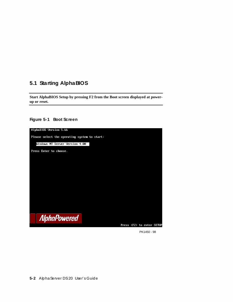
5-2 AlphaServer DS 20 User’s Guide
5.1 Starting AlphaBIOS
Start AlphaBIOS Setup by pressing F2 from the Boot screen displayed at power-up or reset.
Figure 5-1 Boot Screen
PK1450 - 98
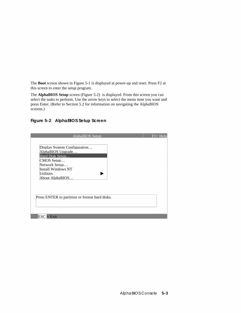
AlphaBIOS Console 5-3
The Boot screen shown in Figure 5-1 is displayed at power-up and reset. Press F2 atthis screen to enter the setup program.
The AlphaBIOS Setup screen (Figure 5-2) is displayed. From this screen you canselect the tasks to perform. Use the arrow keys to select the menu item you want andpress Enter. (Refer to Section 5.2 for information on navigating the AlphaBIOSscreens.)
Figure 5-2 AlphaBIOS Setup Screen
AlphaBIOS Setup F1= Help
Display System Configuration…AlphaBIOS Upgrade…Hard Disk Setup…CMOS Setup…Network Setup…Install Windows NTUtilities æAbout AlphaBIOS…
Press ENTER to partition or format hard disks.
ESC = Exit
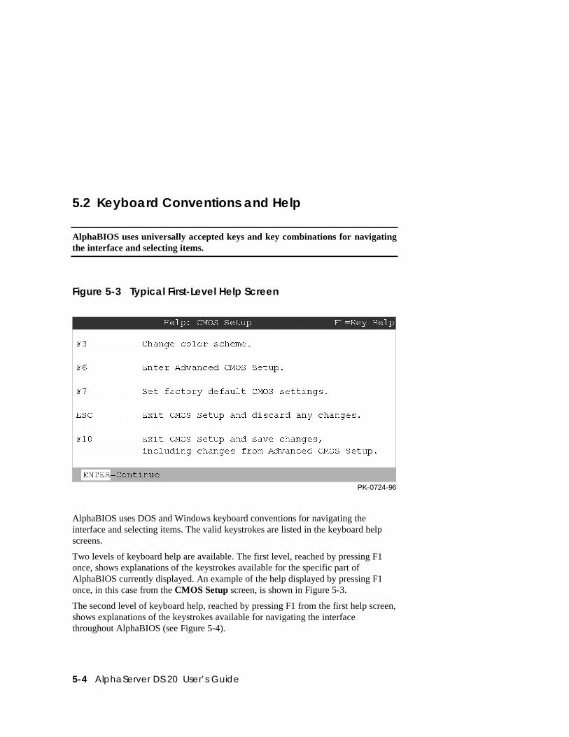
5-4 AlphaServer DS 20 User’s Guide
5.2 Keyboard Conventions and Help
AlphaBIOS uses universally accepted keys and key combinations for navigatingthe interface and selecting items.
Figure 5-3 Typical First-Level Help Screen
Help: CMOS Setup F1=Key Help
F3 Change color scheme.
F6 Enter Advanced CMOS Setup.
F7 Set factory default CMOS settings.
ESC Exit CMOS Setup and discard any changes.
F10 Exit CMOS Setup and save changes,
including changes from Advanced CMOS Setup.
ENTER=Continue
PK-0724-96
AlphaBIOS uses DOS and Windows keyboard conventions for navigating theinterface and selecting items. The valid keystrokes are listed in the keyboard helpscreens.
Two levels of keyboard help are available. The first level, reached by pressing F1once, shows explanations of the keystrokes available for the specific part ofAlphaBIOS currently displayed. An example of the help displayed by pressing F1once, in this case from the CMOS Setup screen, is shown in Figure 5-3.
The second level of keyboard help, reached by pressing F1 from the first help screen,shows explanations of the keystrokes available for navigating the interfacethroughout AlphaBIOS (see Figure 5-4).
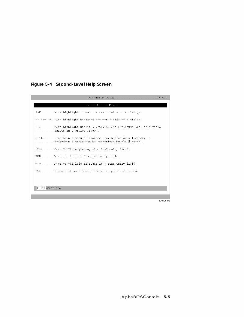
AlphaBIOS Console 5-5
Figure 5-4 Second-Level Help Screen
Help: Action Keys
TAB Move highlight forward between fields of a dialog. SHIFT+TAB Move highlight backward between fields of a dialog. Move highlight within a menu, or cycle through available field values in a dialog window. ALT+ Drop down a menu of choices from a drop-down listbox. A drop-down listbox can be recognized by the symbol. HOME Move to the beginning of a text entry field. END Move to the end of a test entry field. Move to the left or right in a text entry field. ESC Discard changes and/or backup to previous screen.
AlphaBIOS Setup F1=Help
ENTER=Continue
PK-0725-96
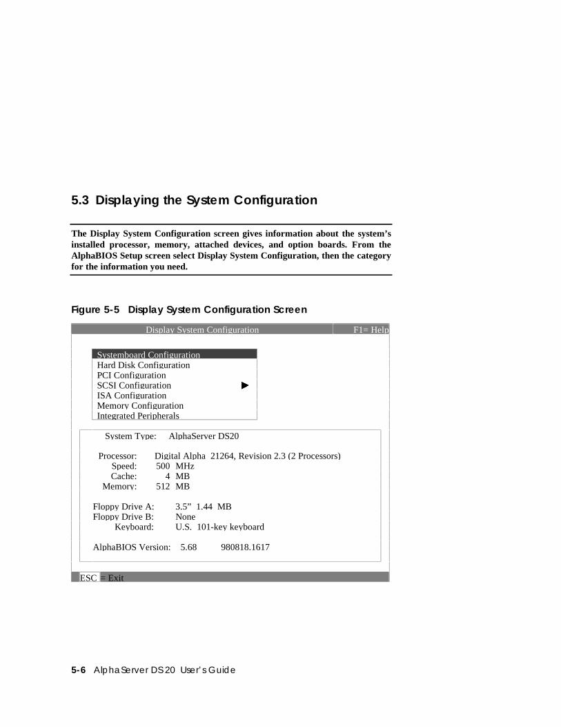
5-6 AlphaServer DS 20 User’s Guide
5.3 Displaying the System Configuration
The Display System Configuration screen gives information about the system’sinstalled processor, memory, attached devices, and option boards. From theAlphaBIOS Setup screen select Display System Configuration, then the categoryfor the information you need.
Figure 5-5 Display System Configuration Screen
Display System Configuration F1= Help
Systemboard Configuration Hard Disk Configuration PCI Configuration SCSI Configuration æ ISA Configuration Memory Configuration Integrated Peripherals
System Type: AlphaServer DS20
Processor: Digital Alpha 21264, Revision 2.3 (2 Processors) Speed: 500 MHz Cache: 4 MB Memory: 512 MB
Floppy Drive A: 3.5” 1.44 MBFloppy Drive B: None Keyboard: U.S. 101-key keyboard
AlphaBIOS Version: 5.68 980818.1617
ESC = Exit
AlphaBIOS Console 5-7
Display the system configuration as follows:
1. Start AlphaBIOS, select Display System Configuration, and press Enter.
2. In the Display System Configuration screen, use the arrow keys to select theconfiguration category you want to see.
From this screen, you can view configuration information about these systemcomponents:
• System board
• Hard disk
• PCI bus
• ISA bus
• SCSI devices
• Memory
• Integrated peripherals
The sections that follow explain the display for each component.
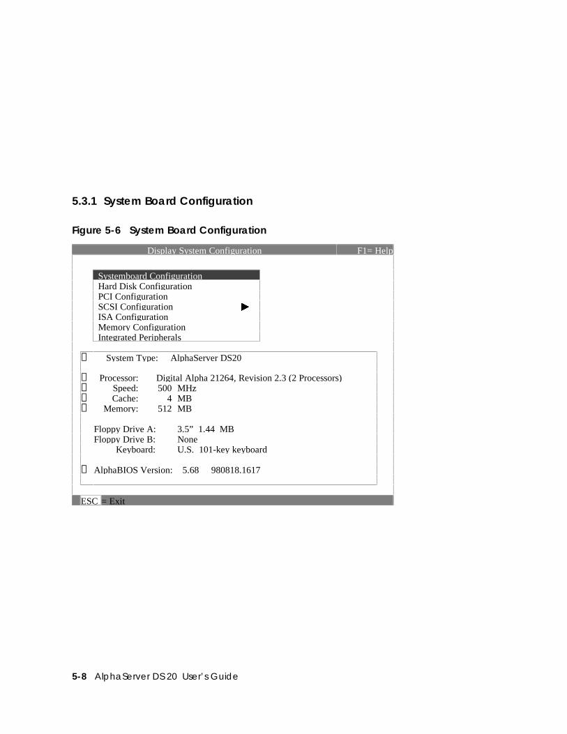
5-8 AlphaServer DS 20 User’s Guide
5.3.1 System Board Configuration
Figure 5-6 System Board Configuration
Display System Configuration F1= Help
Systemboard Configuration Hard Disk Configuration PCI Configuration SCSI Configuration æ ISA Configuration Memory Configuration Integrated Peripherals
➊ System Type: AlphaServer DS20
➋ Processor: Digital Alpha 21264, Revision 2.3 (2 Processors)➌ Speed: 500 MHz➍ Cache: 4 MB➎ Memory: 512 MB
Floppy Drive A: 3.5” 1.44 MBFloppy Drive B: None Keyboard: U.S. 101-key keyboard
➏ AlphaBIOS Version: 5.68 980818.1617
ESC = Exit
AlphaBIOS Console 5-9
➊ System type — The model number of the system.
➋ Processor — The model and revision of the processor chip. Revision-levelinformation can be useful in troubleshooting problems with technical supportpersonnel.
➌ Speed — The speed of the processor.
➍ Cache — The amount of static RAM cache memory installed.
➎ Memory — The amount of main memory in the system.
➏ Firmware version — The version of AlphaBIOS currently running on thesystem.

5-10 AlphaServer DS 20 User’s Guide
5.3.2 Hard Disk Configuration
Figure 5-7 Hard Disk Configuration
Display System Configuration F1= Help
Systemboard Configuration Hard Disk Configuration PCI Configuration SCSI Configuration æ ISA Configuration Memory Configuration Integrated Peripherals
➊Disk 0
➋ ➌ ➍AIC78XX #0, SCSI ID 0
➎4091 MB
DEC RZ1CB-CS (C)Partition 1 4085 MB FATPartition 2 ➏ ➐ 6 MB ➑ FAT
Disk 1 AIC78XX #0, SCSI ID 1 4091 MBDEC RZ1CB-CS (C)Partition 1 4091 MB NTFS
Disk 2 AIC78XX #0. SCSI ID 2 4091 MBDEC RZ1CB-CS (C)Partition 1 4091 MB NTFS
ENTER =Select ESC = Exit
NOTE: This screen is for information only; it cannot be edited. To make changes tothe hard disk setup, use the Hard Disk Setup screen.
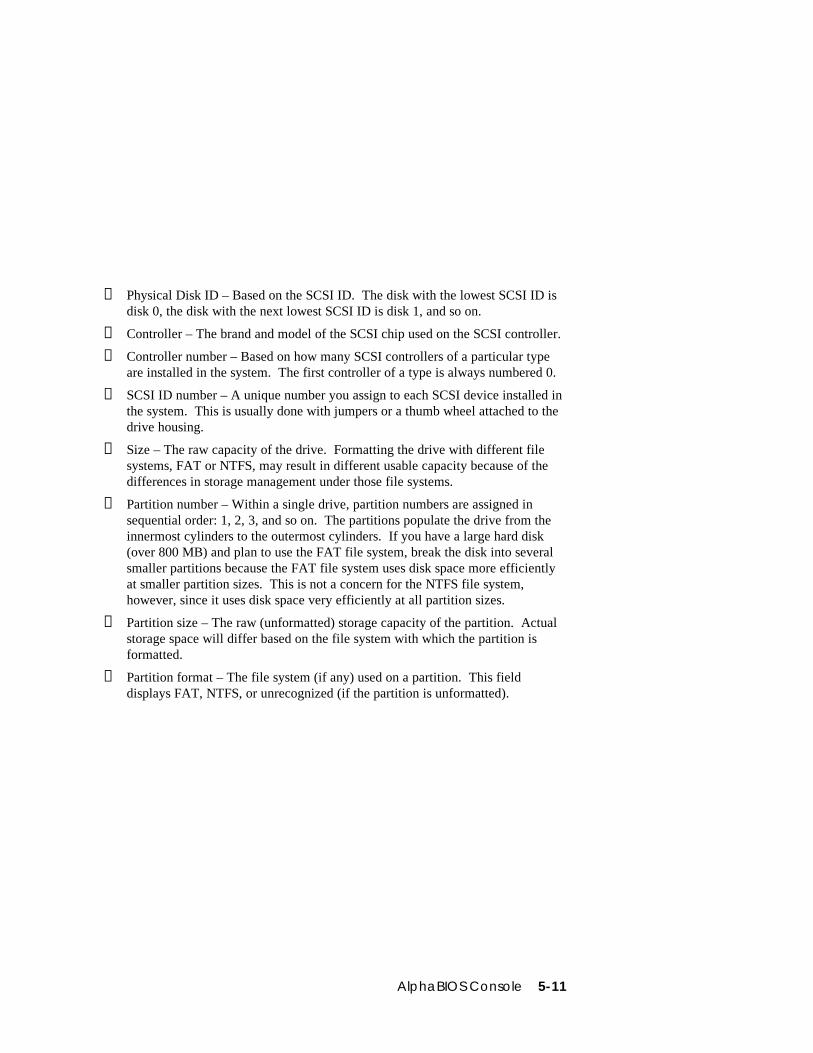
AlphaBIOS Console 5-11
➊ Physical Disk ID – Based on the SCSI ID. The disk with the lowest SCSI ID isdisk 0, the disk with the next lowest SCSI ID is disk 1, and so on.
➋ Controller – The brand and model of the SCSI chip used on the SCSI controller.
➌ Controller number – Based on how many SCSI controllers of a particular typeare installed in the system. The first controller of a type is always numbered 0.
➍ SCSI ID number – A unique number you assign to each SCSI device installed inthe system. This is usually done with jumpers or a thumb wheel attached to thedrive housing.
➎ Size – The raw capacity of the drive. Formatting the drive with different filesystems, FAT or NTFS, may result in different usable capacity because of thedifferences in storage management under those file systems.
➏ Partition number – Within a single drive, partition numbers are assigned insequential order: 1, 2, 3, and so on. The partitions populate the drive from theinnermost cylinders to the outermost cylinders. If you have a large hard disk(over 800 MB) and plan to use the FAT file system, break the disk into severalsmaller partitions because the FAT file system uses disk space more efficientlyat smaller partition sizes. This is not a concern for the NTFS file system,however, since it uses disk space very efficiently at all partition sizes.
➐ Partition size – The raw (unformatted) storage capacity of the partition. Actualstorage space will differ based on the file system with which the partition isformatted.
➑ Partition format – The file system (if any) used on a partition. This fielddisplays FAT, NTFS, or unrecognized (if the partition is unformatted).
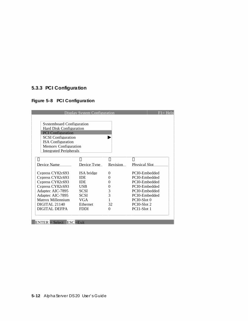
5-12 AlphaServer DS 20 User’s Guide
5.3.3 PCI Configuration
Figure 5-8 PCI Configuration
Display System Configuration F1= Help
Systemboard Configuration Hard Disk Configuration PCI Configuration SCSI Configuration æ ISA Configuration Memory Configuration Integrated Peripherals
➊Device Name
➋Device Type
➌Revision
➍Physical Slot
Cypress CY82c693 ISA bridge 0 PCI0-EmbeddedCypress CY82c693 IDE 0 PCI0-EmbeddedCypress CY82c693 IDE 0 PCI0-EmbeddedCypress CY82c693 USB 0 PCI0-EmbeddedAdaptec AIC-7895 SCSI 3 PCI0-EmbeddedAdaptec AIC-7895 SCSI 3 PCI0-EmbeddedMatrox Millennium VGA 1 PCI0-Slot 0DIGITAL 21140 Ethernet 32 PCI0-Slot 2DIGITAL DEFPA FDDI 0 PCI1-Slot 1
ENTER = Select ESC =Exit

AlphaBIOS Console 5-13
➊ Device name — The name and model of the device as recorded in the device’sfirmware.
➋ Device type — Lists the function of the device in the system.
➌ Revision — The revision level of the device signifies the number of times it hasbeen updated by the manufacturer.
➍ Physical slot — Lists the actual PCI slot number to which the device is attached.
You can find additional detail about any of the PCI devices listed in the AdvancedPCI Information screen. Follow this procedure to view this screen:
1. Press Enter to enable selection in the device list.
2. Use the arrow keys to select the device for which you want additional detail.
3. Press Enter, and the detail is displayed.
4. Press Escape to return to the table of PCI devices.
The Advanced PCI Information screen is shown in Figure 5-9 on the next page.
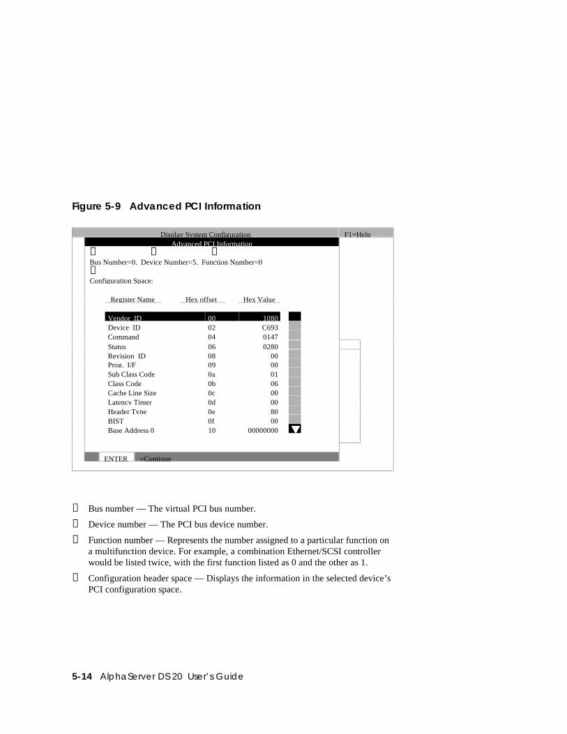
5-14 AlphaServer DS 20 User’s Guide
Figure 5-9 Advanced PCI Information
Display System Configuration F1=HelpAdvanced PCI Information
➊ ➋ ➌Bus Number=0, Device Number=5, Function Number=0➍Configuration Space:
Register Name Hex offset Hex Value
Vendor ID 00 1080Device ID 02 C693Command 04 0147Status 06 0280Revision ID 08 00Prog. I/F 09 00Sub Class Code 0a 01Class Code 0b 06Cache Line Size 0c 00Latency Timer 0d 00Header Type 0e 80BIST 0f 00Base Address 0 10 00000000 å
ENTER =Continue
➊ Bus number — The virtual PCI bus number.
➋ Device number — The PCI bus device number.
➌ Function number — Represents the number assigned to a particular function ona multifunction device. For example, a combination Ethernet/SCSI controllerwould be listed twice, with the first function listed as 0 and the other as 1.
➍ Configuration header space — Displays the information in the selected device’sPCI configuration space.
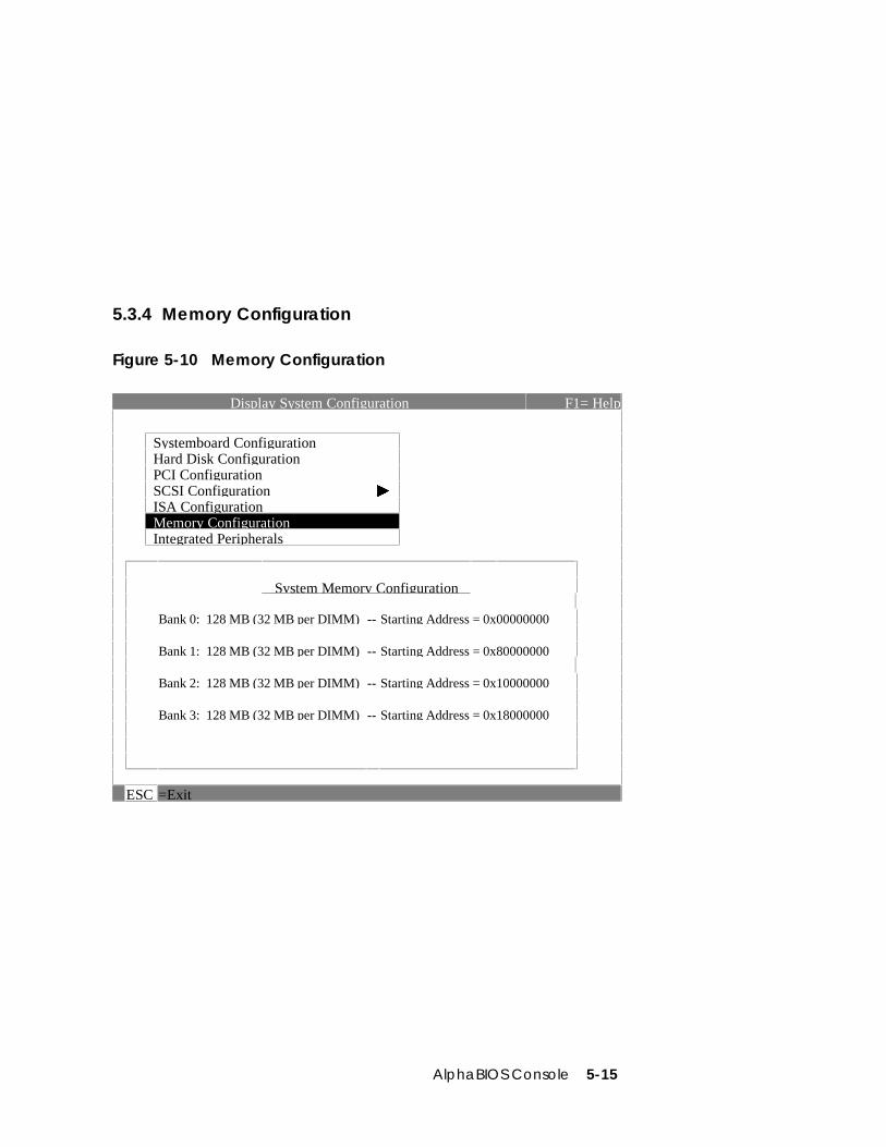
AlphaBIOS Console 5-15
5.3.4 Memory Configuration
Figure 5-10 Memory Configuration
Display System Configuration F1= Help
Systemboard Configuration Hard Disk Configuration PCI Configuration SCSI Configuration æ ISA Configuration Memory Configuration Integrated Peripherals
System Memory Configuration
Bank 0: 128 MB (32 MB per DIMM) -- Starting Address = 0x00000000
Bank 1: 128 MB (32 MB per DIMM) -- Starting Address = 0x80000000
Bank 2: 128 MB (32 MB per DIMM) -- Starting Address = 0x10000000
Bank 3: 128 MB (32 MB per DIMM) -- Starting Address = 0x18000000
ESC =Exit
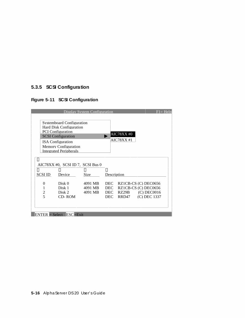
5-16 AlphaServer DS 20 User’s Guide
5.3.5 SCSI Configuration
Figure 5-11 SCSI Configuration
Display System Configuration F1= Help
Systemboard Configuration Hard Disk Configuration PCI Configuration
AIC78XX #0 SCSI Configuration æAIC78XX #1 ISA Configuration
Memory Configuration Integrated Peripherals
➊ AIC78XX #0, SCSI ID 7, SCSI Bus 0➋ ➌ ➍ ➎SCSI ID Device Size Description
0 Disk 0 4091 MB DEC RZ1CB-CS (C) DEC06561 Disk 1 4091 MB DEC RZ1CB-CS (C) DEC06562 Disk 2 4091 MB DEC RZ29B (C) DEC00165 CD- ROM DEC RRD47 (C) DEC 1337
ENTER = Select ESC =Exit
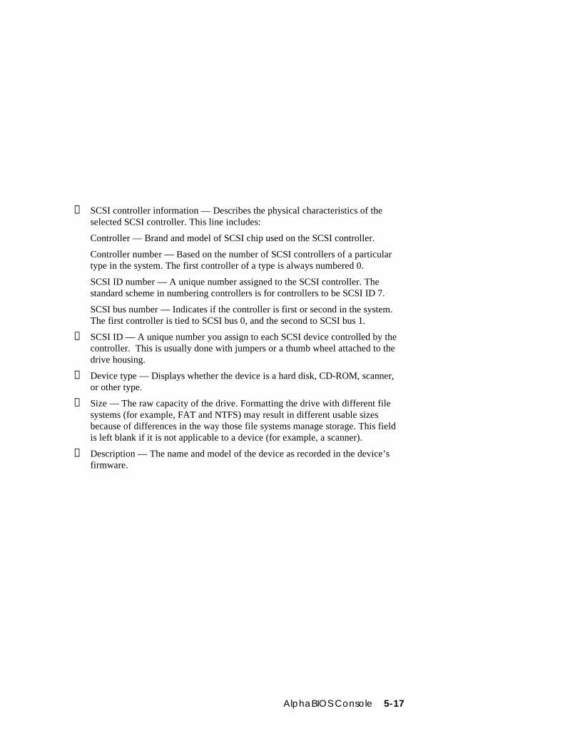
AlphaBIOS Console 5-17
➊ SCSI controller information — Describes the physical characteristics of theselected SCSI controller. This line includes:
Controller — Brand and model of SCSI chip used on the SCSI controller.
Controller number — Based on the number of SCSI controllers of a particulartype in the system. The first controller of a type is always numbered 0.
SCSI ID number — A unique number assigned to the SCSI controller. Thestandard scheme in numbering controllers is for controllers to be SCSI ID 7.
SCSI bus number — Indicates if the controller is first or second in the system.The first controller is tied to SCSI bus 0, and the second to SCSI bus 1.
➋ SCSI ID — A unique number you assign to each SCSI device controlled by thecontroller. This is usually done with jumpers or a thumb wheel attached to thedrive housing.
➌ Device type — Displays whether the device is a hard disk, CD-ROM, scanner,or other type.
➍ Size — The raw capacity of the drive. Formatting the drive with different filesystems (for example, FAT and NTFS) may result in different usable sizesbecause of differences in the way those file systems manage storage. This fieldis left blank if it is not applicable to a device (for example, a scanner).
➎ Description — The name and model of the device as recorded in the device’sfirmware.
5-18 AlphaServer DS 20 User’s Guide
5.3.6 Integrated Peripherals
Figure 5-12 Integrated Peripherals
Display System Configuration F1=Help
Systemboard ConfigurationHard Disk ConfigurationPCI ConfigurationSCSI ConfigurationISA ConfigurationMemory ConfigurationIntegrated Peripherals
Integrated Peripheral State➊ ➋ ➌ ➍Serial 0: Enabled [ port 0x3f8, IRQ 4 ]Serial 1: Enabled [ port 0x2f8, IRQ 3]Parallel: Enabled [ port 0/3bc, IRQ 7]Floppy Ctrl: Enabled [ port 0/3f0, IRQ 6]IDE 0: DisabledCypress IDE Chnl 0: Enabled [ port 0x1f0, IRQ 14]Cypress IDE Chnl 1: Enabled [ port 0x170, IRQ 15]
ESC =Exit
AlphaBIOS Console 5-19
➊ Device type — The physical device as it exists on the system board.
➋ MS-DOS name — Shows if the device is enabled, and if it is enabled, theaddressable MS-DOS name for the device.
➌ Port address — The physical memory location for data received into the device,and sent from the device, respectively.
➍ Interrupt — The interrupt request line (IRQ) used by the device to get the CPU’sattention.
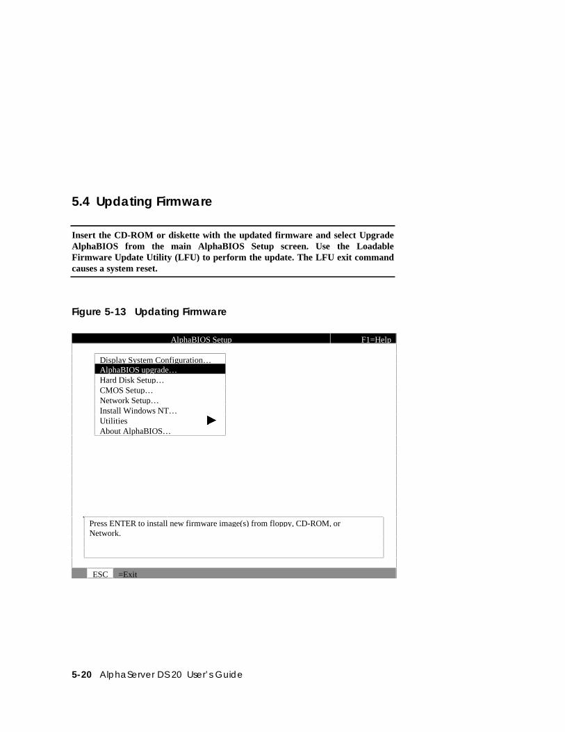
5-20 AlphaServer DS 20 User’s Guide
5.4 Updating Firmware
Insert the CD-ROM or diskette with the updated firmware and select UpgradeAlphaBIOS from the main AlphaBIOS Setup screen. Use the LoadableFirmware Update Utility (LFU) to perform the update. The LFU exit commandcauses a system reset.
Figure 5-13 Updating Firmware
AlphaBIOS Setup F1=Help
Display System Configuration…AlphaBIOS upgrade…Hard Disk Setup…CMOS Setup…Network Setup…Install Windows NT…Utilities æAbout AlphaBIOS…
Press ENTER to install new firmware image(s) from floppy, CD-ROM, orNetwork.
ESC =Exit
AlphaBIOS Console 5-21
As new versions of Windows NT are released, it might be necessary to upgradeAlphaBIOS to the latest version. Also, as improvements are made to AlphaBIOS,you may wish to upgrade to take advantage of new features.
Use this procedure to upgrade from an earlier version of AlphaBIOS:
1. Insert the diskette or CD-ROM containing the AlphaBIOS upgrade.
2. If you are not already running AlphaBIOS Setup, restart your system and pressF2 when the Boot screen is displayed.
3. In the main AlphaBIOS Setup screen, select AlphaBIOS Upgrade and pressEnter.
The system is reset and the Loadable Firmware Update (LFU) utility is started.
4. When the upgrade is complete, issue the LFU exit command. The system is resetand you are returned to AlphaBIOS.
If you press the Reset button instead of issuing the LFU exit command, thesystem is reset and you are returned to LFU.
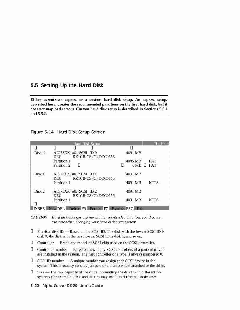
5-22 AlphaServer DS 20 User’s Guide
5.5 Setting Up the Hard Disk
Either execute an express or a custom hard disk setup. An express setup,described here, creates the recommended partitions on the first hard disk, but itdoes not map bad sectors. Custom hard disk setup is described in Sections 5.5.1and 5.5.2.
Figure 5-14 Hard Disk Setup Screen
Hard Disk Setup F1= Help➊Disk 0
➋ ➌ ➍AIC78XX #0, SCSI ID 0
➎4091 MB
DEC RZ1CB-CS (C) DEC0656Partition 1 4085 MB FATPartition 2 ➏ ➐ 6 MB ➑ FAT
Disk 1 AIC78XX #0, SCSI ID 1 4091 MBDEC RZ1CB-CS (C) DEC0656Partition 1 4091 MB NTFS
Disk 2 AIC78XX #0. SCSI ID 2 4091 MBDEC RZ1CB-CS (C) DEC0656Partition 1 4091 MB NTFS
➒INSER =New DEL = Delete F6 =Format F7 =Express ESC =Exit
CAUTION: Hard disk changes are immediate; unintended data loss could occur,use care when changing your hard disk arrangement.
➊ Physical disk ID — Based on the SCSI ID. The disk with the lowest SCSI ID isdisk 0, the disk with the next lowest SCSI ID is disk 1, and so on.
➋ Controller — Brand and model of SCSI chip used on the SCSI controller.
➌ Controller number — Based on how many SCSI controllers of a particular typeare installed in the system. The first controller of a type is always numbered 0.
➍ SCSI ID number — A unique number you assign each SCSI device in thesystem. This is usually done by jumpers or a thumb wheel attached to the drive.
➎ Size — The raw capacity of the drive. Formatting the drive with different filesystems (for example, FAT and NTFS) may result in different usable sizes
AlphaBIOS Console 5-23
because of the differences in how storage is managed under those file systems.
➏ Partition number — Within a single drive, partition numbers are assigned insequential order: 1, 2, 3, and so on. The partitions populate the drive from theinnermost cylinders to the outermost. If you have a large hard disk (over 800MB) and plan to use the FAT file system, it is a good idea to break the disk intoseveral smaller partitions because the FAT file system uses disk space moreefficiently at smaller partition sizes. This is not necessary for the NTFS filesystem, since it uses disk space very efficiently at all partition sizes.
➐ Partition size — The raw (unformatted) storage capacity of the partition. Actualstorage space will differ based on the file system with which the partition isformatted.
➑ Partition format — The file system (if any) used on a partition. This fielddisplays FAT, NTFS, or unrecognized (if the partition is unformatted).
➒ Disk setup options
Insert partition (Insert key) — Use this option to create new partitions. Beforecreating a new partition, be sure to select an unpartitioned space. Pressing theInsert key while an already partitioned space is selected causes an informationalerror to be displayed.
Delete partition (Delete key) — Use this option to delete existing partitions.Before deleting a partition, be sure to back up any data you want to save on thepartition. Deleting a partition deletes all data on that partition but leaves the restof the disk unaffected. Pressing the Delete key while an unpartitioned space isselected displays an informational error.
Format partition (F6 key) — Format a partitioned space with the FAT filesystem.
Express setup (F7 key) — Create the default recommended partitionarrangement for Windows NT.
Exit (Escape key) — Return to the AlphaBIOS Setup screen.
An express hard disk setup creates the recommended partition arrangement on thefirst hard disk (disk 0). It does not, however, format the large partition with NTFS,and it does not map bad sectors on the disk. The NTFS formatting can be doneduring Windows NT installation.
To perform an express hard disk setup
1. If you have any needed information on your disk, back it up before proceeding.
2. Start AlphaBIOS Setup, select Hard Disk Setup, and press Enter.
3. Press F7 to enter Express Setup.
4. Press F10 to continue with the setup.
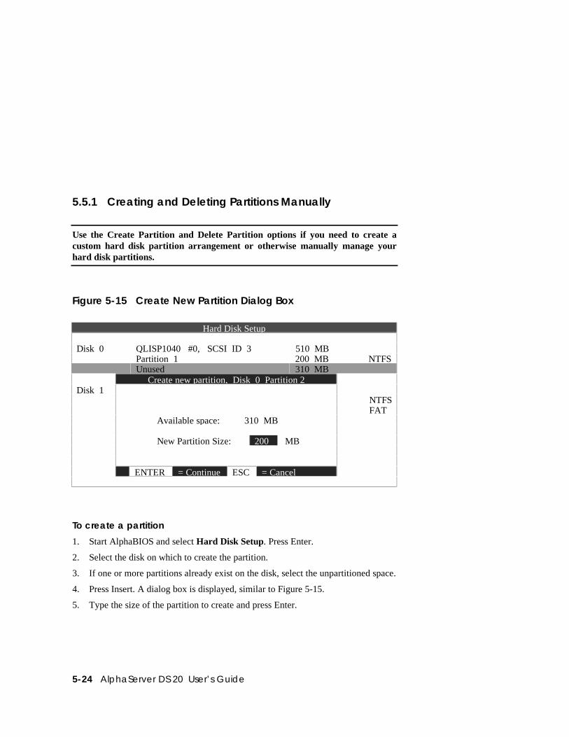
5-24 AlphaServer DS 20 User’s Guide
5.5.1 Creating and Deleting Partitions Manually
Use the Create Partition and Delete Partition options if you need to create acustom hard disk partition arrangement or otherwise manually manage yourhard disk partitions.
Figure 5-15 Create New Partition Dialog Box
Hard Disk Setup
Disk 0 QLISP1040 #0, SCSI ID 3 510 MBPartition 1 200 MB NTFSUnused 310 MB
Create new partition, Disk 0 Partition 2Disk 1
NTFSFAT
Available space: 310 MB
New Partition Size: 200 MB
ENTER = Continue ESC = Cancel
To create a partition
1. Start AlphaBIOS and select Hard Disk Setup. Press Enter.
2. Select the disk on which to create the partition.
3. If one or more partitions already exist on the disk, select the unpartitioned space.
4. Press Insert. A dialog box is displayed, similar to Figure 5-15.
5. Type the size of the partition to create and press Enter.
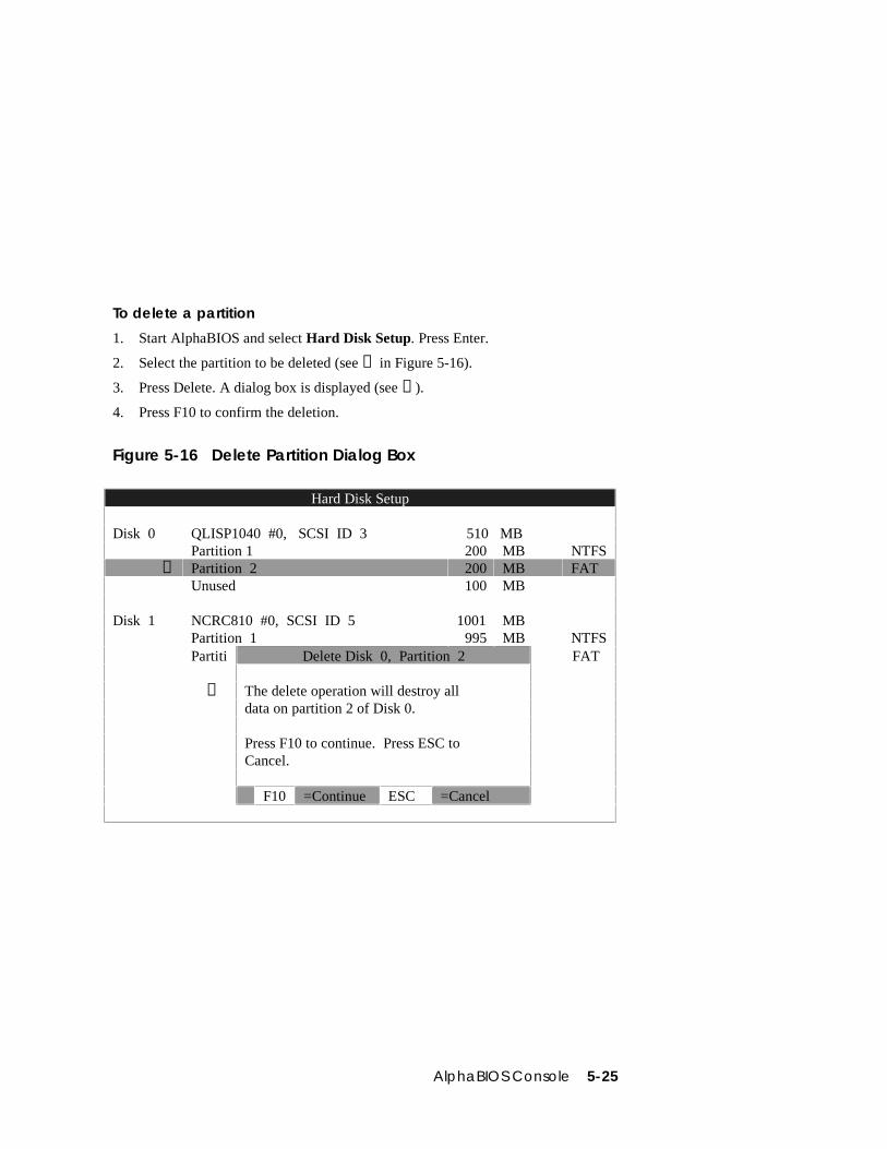
AlphaBIOS Console 5-25
To delete a partition
1. Start AlphaBIOS and select Hard Disk Setup. Press Enter.
2. Select the partition to be deleted (see ➊ in Figure 5-16).
3. Press Delete. A dialog box is displayed (see ➋).
4. Press F10 to confirm the deletion.
Figure 5-16 Delete Partition Dialog Box
Hard Disk Setup
Disk 0 QLISP1040 #0, SCSI ID 3 510 MBPartition 1 200 MB NTFS
➊ Partition 2 200 MB FATUnused 100 MB
Disk 1 NCRC810 #0, SCSI ID 5 1001 MBPartition 1 995 MB NTFSPartiti Delete Disk 0, Partition 2 FAT
➋ The delete operation will destroy alldata on partition 2 of Disk 0.
Press F10 to continue. Press ESC toCancel.
F10 =Continue ESC =Cancel
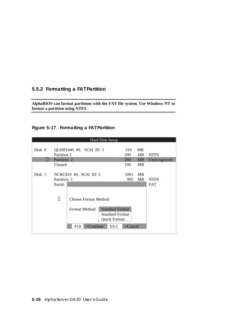
5-26 AlphaServer DS 20 User’s Guide
5.5.2 Formatting a FAT Partition
AlphaBIOS can format partitions with the FAT file system. Use Windows NT toformat a partition using NTFS.
Figure 5-17 Formatting a FAT Partition
Hard Disk Setup
Disk 0 QLISP1040 #0, SCSI ID 3 510 MBPartition 1 200 MB NTFS
➊ Partition 2 200 MB UnrecognizedUnused 100 MB
Disk 1 NCRC810 #0, SCSI ID 5 1001 MBPartition 1 995 MB NTFSPartiti FAT
➋ Choose Format Method:
Format Method: Standard FormatStandard FormatQuick Format
F10 =Continue ES C =Cancel
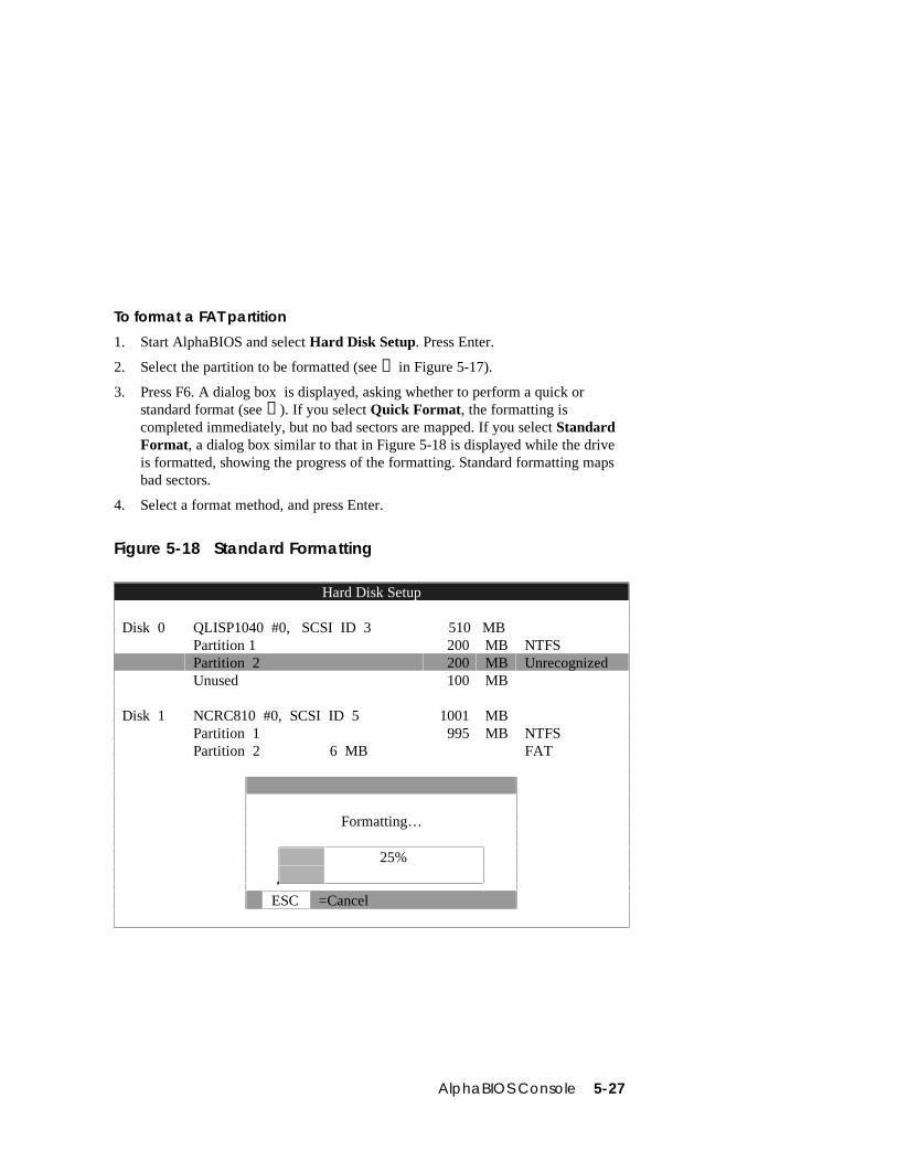
AlphaBIOS Console 5-27
To format a FAT partition
1. Start AlphaBIOS and select Hard Disk Setup. Press Enter.
2. Select the partition to be formatted (see ➊ in Figure 5-17).
3. Press F6. A dialog box is displayed, asking whether to perform a quick orstandard format (see ➋). If you select Quick Format, the formatting iscompleted immediately, but no bad sectors are mapped. If you select StandardFormat, a dialog box similar to that in Figure 5-18 is displayed while the driveis formatted, showing the progress of the formatting. Standard formatting mapsbad sectors.
4. Select a format method, and press Enter.
Figure 5-18 Standard Formatting
Hard Disk Setup
Disk 0 QLISP1040 #0, SCSI ID 3 510 MBPartition 1 200 MB NTFSPartition 2 200 MB UnrecognizedUnused 100 MB
Disk 1 NCRC810 #0, SCSI ID 5 1001 MBPartition 1 995 MB NTFSPartition 2 6 MB FAT
Formatting…
25%
ESC =Cancel
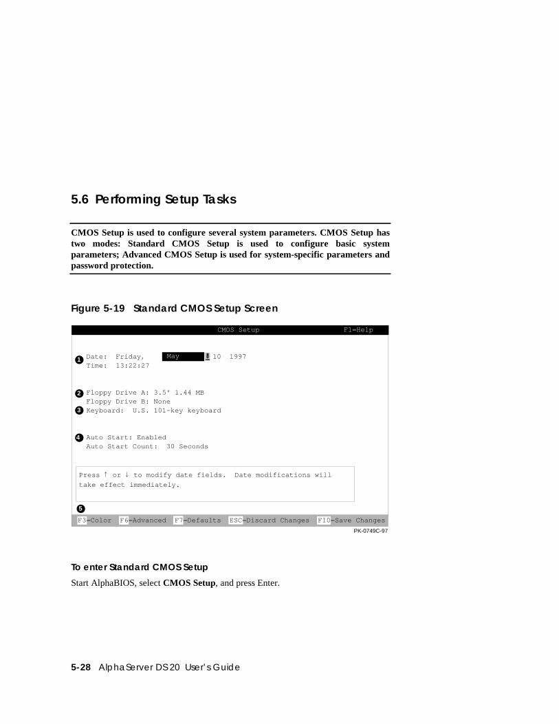
5-28 AlphaServer DS 20 User’s Guide
5.6 Performing Setup Tasks
CMOS Setup is used to configure several system parameters. CMOS Setup hastwo modes: Standard CMOS Setup is used to configure basic systemparameters; Advanced CMOS Setup is used for system-specific parameters andpassword protection.
Figure 5-19 Standard CMOS Setup Screen
Date: Friday, 10 1997Time: 13:22:27
Floppy Drive A: 3.5" 1.44 MBFloppy Drive B: NoneKeyboard: U.S. 101-key keyboard
Auto Start: EnabledAuto Start Count: 30 Seconds
CMOS Setup F1=Help
May
Press or to modify date fields. Date modifications will
take effect immediately.
F3=Color F6=Advanced F7=Defaults ESC=Discard Changes F10=Save Changes
PK-0749C-97
1
2
3
4
5
To enter Standard CMOS Setup
Start AlphaBIOS, select CMOS Setup, and press Enter.
AlphaBIOS Console 5-29
➊ Date and time — When setting the time, use the 24-hour format. (For example,10:00 p.m. is 22:00:00.)
➋ Floppy drive — The only drive type supported is 3.5 inch, 1.44 MB.
➌ Keyboard — The keyboard setting makes it possible to use most languagekeyboards. To ensure correct character mappings, the language of yourkeyboard, Windows NT, and the keyboard language selection in CMOS Setupshould all match.
➍ Auto start and auto start count — The Auto Start setting determines whether theprimary operating system is automatically started after the system is reset orpower-cycled. The Auto Start Count setting is the amount of time the Bootscreen is displayed before the default system is automatically started. This delaygives you the opportunity, after resetting or power-cycling the system, to selectanother version of Windows NT to start or to enter AlphaBIOS Setup.
➎ Standard CMOS Setup options
Color (F3 key) — Repeatedly cycles through the available AlphaBIOS colorschemes.
Advanced (F6 key) — Displays the Advanced CMOS Setup screen.
Defaults (F7 key) — Restores the default Standard CMOS Setup valueswithout affecting the Advanced CMOS Setup values.
Discard changes (Escape key) — Restores the settings in effect when you startedCMOS Setup. This option also discards changes made in Advanced CMOSSetup.
Save changes (F10 key) — Saves changes made in both the standard andadvanced modes of CMOS Setup.
Continued on next page
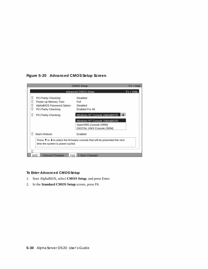
5-30 AlphaServer DS 20 User’s Guide
Figure 5-20 Advanced CMOS Setup Screen
CMOS Setup F1 = Help
Advanced CMOS Setup F1 = Help
➊ PCI Parity Checking: Disabled➋ Power-up Memory Test: Full➌ AlphaBIOS Password Option: Disabled➍ PCI Parity Checking: Enabled For All
➎ PCI Parity Checking: Windows NT Console (AlphaBIOS) ¼
Windows NT Console (AlphaBIOS)
OpenVMS Console (SRM)DIGITAL UNIX Console (SRM)
➏ Warm Reboot: Enabled
Press ½ or ¼ to select the firmware console that will be presented the nexttime the system is power-cycled.
➐ESC = Discard Changes F10 = Save Changes
To Enter Advanced CMOS Setup
1. Start AlphaBIOS, select CMOS Setup, and press Enter.
2. In the Standard CMOS Setup screen, press F6.
AlphaBIOS Console 5-31
➊ PCI parity checking — Enables and disables settings for PCI parity checking,which ensures data integrity across the PCI bus. Because some third-party PCIoptions do not correctly implement PCI parity generation, the default isDisabled.
➋ Power-up memory test — Enables and disables settings for the power-upmemory test.
➌ Password setup — Enables and disables settings for password setup.
Password protection provides two levels of security for your system: setup,which requires a password to start AlphaBIOS Setup, and startup, whichrequires a password before the system initializes. Startup protection providesmore comprehensive protection than setup protection because the system cannotbe used at all until the correct password is entered.
➍ Console selection — Switches from AlphaBIOS to SRM firmware. If you selectOpenVMS (SRM) or DIGITAL UNIX (SRM), the next time you reset yoursystem, the SRM firmware will be loaded instead of AlphaBIOS. This menuselection changes the setting of the os_type environment variable in the SRMconsole.
➎ Memory test length — Selects the length of memory testing that will be done thenext time the system is power-cycled.
➏ Warm Reboot — Enable (the default) results in the system restarting normallyon a shutdown and restart from the operating system. Disable results in thenecessity to restart the machine by pressing reset or power-cycling.
➐ Advanced CMOS Setup options
Discard changes (Escape key) —Restores those settings in effect when youstarted Advanced CMOS Setup. This does not discard changes made toStandard CMOS Setup.
Save Changes (F10 key) — Saves changes made in Advanced CMOS Setup.When exiting CMOS Setup, you must also save your changes at the StandardCMOS Setup screen for the changes to be stored permanently.
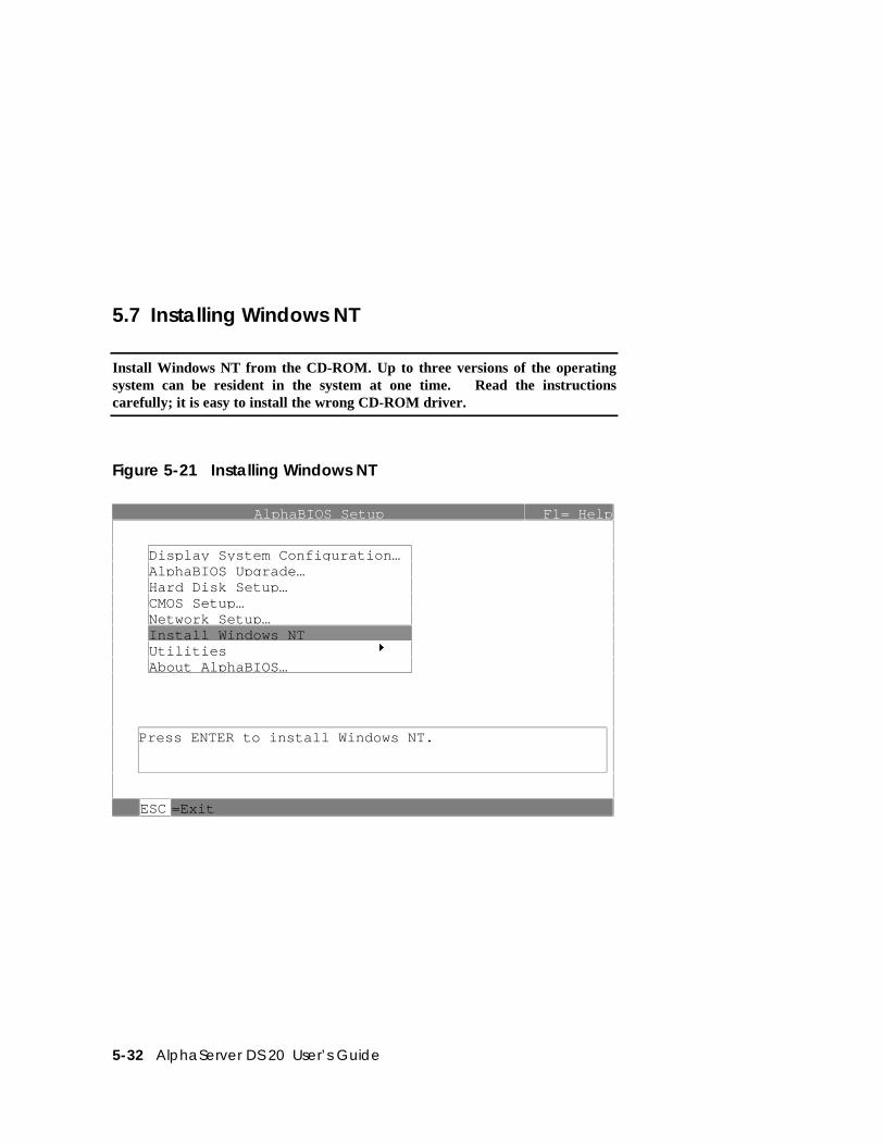
5-32 AlphaServer DS 20 User’s Guide
5.7 Installing Windows NT
Install Windows NT from the CD-ROM. Up to three versions of the operatingsystem can be resident in the system at one time. Read the instructionscarefully; it is easy to install the wrong CD-ROM driver.
Figure 5-21 Installing Windows NT
AlphaBIOS Setup F1= Help
Dis pla y S ystem Confi guration…Al phaBIOS U pgrade…Hard Disk Setu p…CMOS Setup…Network Setu p…Install Windows NTUtilities 8About Al phaBIOS…
Press ENTER to install Windows NT.
ESC =Exit
AlphaBIOS Console 5-33
If Windows NT was installed at the factory, Windows NT setup will startautomatically the first time the system powers up.
NOTE: Steps 1 and 2 in the following procedure are necessary only when you arefirst setting up your system. On subsequent installations and upgrades,begin at step 3.
Read these instructions carefully paying particular attention to step 5.
1. Use CMOS Setup to set the system date and time: start AlphaBIOS Setup,select CMOS Setup, and press Enter.
2. Perform an express hard disk setup: return to the main AlphaBIOS Setupscreen, select Hard Disk Setup, and press Enter.
3. Put the Windows NT CD into the CD-ROM drive.
4. Start AlphaBIOS Setup, select Install Windows NT, and press Enter.
5. Windows NT 4.0 Setup incorrectly believes that it recognizes and supports theunused onboard AIC-7895 SCSI controller and will load its driver unless it isprevented from doing so. Your system’s CD-ROM is connected to a SCSIcontroller on the PCI bus and its driver must be loaded. To prevent the loadingof the WRONG driver, quickly press F6 when the Windows NT banner displays(blue screen). If Windows NT autodetects the AIC-78xx and F6 was not pressedat the right time, start over again. For further information, see the Windows NT4.0 readme.txt file.
6. To select the appropriate driver:
a. Insert the AlphaServer DS20 Windows NT floppy into the floppy drive.
b. If step 5 was successful, Windows NT Setup will announce that it cannotdetermine the type of one or more mass storage controllers, press ’S’ tospecify an additional controller.
c. From the list, choose “Other.” The floppy’s list will appear.
d. Choose the “Adaptec AIC-78xx PCI SCSI Controller (NT4.0).”
Follow the prompts to complete the installation. For more information on installingWindows NT, refer to the Installation Guide in your Windows NT software package.
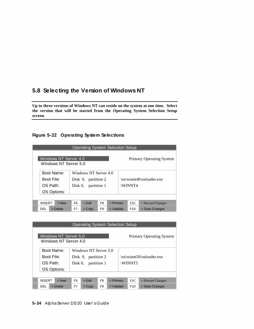
5-34 AlphaServer DS 20 User’s Guide
5.8 Selecting the Version of Windows NT
Up to three versions of Windows NT can reside on the system at one time. Selectthe version that will be started from the Operating System Selection Setupscreen.
Figure 5-22 Operating System Selections
Operating System Selection Setup
Windows NT Server 4.0 Primary Operating System Windows NT Server 5.0
Boot Name: Windows NT Server 4.0
Boot File: Disk 0, partition 2 \os\winnt40\osloader.exe
OS Path: Disk 0, partition 1 \WINNT4
OS Options:
INSERT = New F6 = Edit F8 = Primary ESC = Discard Changes
DEL = Delete F7 = Copy F9 = Validate F10 = Save Changes
Operating System Selection Setup
Windows NT Server 5.0 Primary Operating System Windows NT Server 4.0
Boot Name: Windows NT Server 5.0
Boot File: Disk 0, partition 2 \os\winnt50\osloader.exe
OS Path: Disk 0, partition 1 \WINNT5
OS Options:
INSERT = New F6 = Edit F8 = Primary ESC = Discard Changes
DEL = Delete F7 = Copy F9 = Validate F10 = Save Changes
AlphaBIOS Console 5-35
NOTE: The term “operating system selection,” as it is used in this context, refers toa version of Windows NT. It does not pertain to the DIGITAL UNIX andOpenVMS operating systems.
Each operating system selection is a set of information for a version of Windows NT.It describes the disk and partition containing the OSLOADER.EXE file associatedwith a particular operating system installation, as well as the path to the operatingsystem itself. In addition, the operating system selection contains any options passedto the operating system during boot.
By default, one operating system selection is displayed on the AlphaBIOS Bootscreen for each operating system installed on the system. It is not normally necessaryto modify operating system selections, since the Windows NT installation createsand modifies operating system selections as needed. If you add SCSI controllersafter the installation of Windows NT, it may be necessary to modify operatingsystem selections. Depending on what kind of SCSI controller is added, in which slotit is placed, and where its driver is in the startup order relative to other existingcontrollers, the disk numbering may change and modification of operating systemselections may be required.
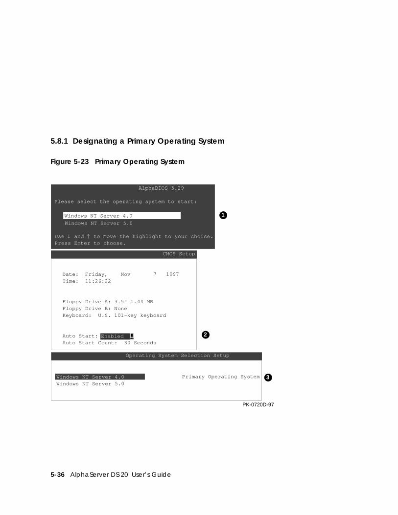
5-36 AlphaServer DS 20 User’s Guide
5.8.1 Designating a Primary Operating System
Figure 5-23 Primary Operating System
AlphaBIOS 5.29
Please select the operating system to start:
Use and to move the highlight to your choice.Press Enter to choose.
CMOS Setup
Date: Friday, Nov 7 1997Time: 11:26:22
Floppy Drive A: 3.5" 1.44 MBFloppy Drive B: NoneKeyboard: U.S. 101-key keyboard
Auto Start:Auto Start Count: 30 Seconds
Enabled
Operating System Selection Setup
Windows NT Server 4.0 Primary Operating System
PK-0720D-97
1
2
3
Windows NT Server 4.0
Windows NT Server 5.0
Windows NT Server 5.0
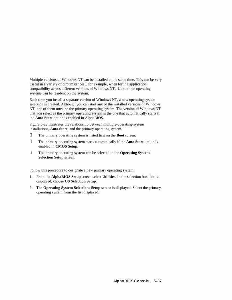
AlphaBIOS Console 5-37
Multiple versions of Windows NT can be installed at the same time. This can be veryuseful in a variety of circumstancesfor example, when testing applicationcompatibility across different versions of Windows NT. Up to three operatingsystems can be resident on the system.
Each time you install a separate version of Windows NT, a new operating systemselection is created. Although you can start any of the installed versions of WindowsNT, one of them must be the primary operating system. The version of Windows NTthat you select as the primary operating system is the one that automatically starts ifthe Auto Start option is enabled in AlphaBIOS.
Figure 5-23 illustrates the relationship between multiple-operating-systeminstallations, Auto Start, and the primary operating system.
➊ The primary operating system is listed first on the Boot screen.
➋ The primary operating system starts automatically if the Auto Start option isenabled in CMOS Setup.
➌ The primary operating system can be selected in the Operating SystemSelection Setup screen.
Follow this procedure to designate a new primary operating system:
1. From the AlphaBIOS Setup screen select Utilities. In the selection box that isdisplayed, choose OS Selection Setup.
2. The Operating System Selections Setup screen is displayed. Select the primaryoperating system from the list displayed.
5-38 AlphaServer DS 20 User’s Guide
5.8.2 Primary Operating System and the Auto Start OptionThe process of setting up your operating system selections is similar to using aneditor. You can make changes to your operating system selections and then eithersave your changes or exit without saving.
Figure 5-24 Operating System Selection Setup
Operating System Selection Setup
Windows NT Server 4.0 Primary Operating System
Boot Name: Windows NT Server 4.0Boot File: Disk 0, Partition 2 \os\winnt400\osloader.exeOS Path: Disk 0, Partition 1 \WINNT400OS Options:
INSERT=New F6=Edit F8=Primary ESC=Discard ChangesDEL=Delete F7=Copy F9=Validate F10=Save Changes
PK-0737C-97
6
2
1
4
5
3
AlphaBIOS boots Windows NT in two stages. The first stage involves reading an OSLoader program from a disk. The OS Loader program is named OSLOADER.EXE.The selection for the operating system must describe the path where AlphaBIOS willfind the OS Loader program. The OS Loader program must be located on a partitionformatted with the FAT file system.
Once the OS Loader program executes, it uses the services provided by AlphaBIOSto load the operating system components. After the operating system is loaded, theOS Loader starts execution of the operating system.
AlphaBIOS Console 5-39
➊ Primary operating system — The OS that appears first on the AlphaBIOS Bootscreen. It is also the version of the OS that automatically starts if Auto Start isselected. Any of the operating system selections can be the primary operatingsystem.
➋ Boot name — Each boot name is associated with an operating system selection.Windows NT setup automatically creates a boot name each time you install theoperating system. Because the boot name is only a name, you can modify it atany time without affecting the rest of the operating system selection. The bootname must have at least one character.
➌ Boot file — Describes the disk, partition, path, and name of the file thatAlphaBIOS passes control to during the process of starting the operating system.This setting is created along with the operating system selection duringWindows NT setup, and the user does not usually modify it. However, thissetting can be modified if necessary. For example, a developer testing differentversions of OSLOADER.EXE can store the different versions in differentlocations and modify this line to start the operating system with the differentversions as needed.
During Operating System Selection Setup, you can select the disk and partitionfor the location of the boot file from a list of choices presented in a list box. Toopen a list of values for the field, press the Alt and down arrow keys together.When you select a boot file location and name, AlphaBIOS searches for thespecified program on the specified partition. If the search fails, a warning isdisplayed, saying that the file does not exist. You are given the choice tocontinue with the changes anyway or to cancel the operation and fix theproblem.
➍ OS path — Describes the disk, partition, and path to the operating system rootdirectory for an operating system selection.
During Operating System Selection Setup, you can select the disk and partitionfor the location of the boot file from a list of choices presented in a list box. Toopen a list of possible values for the field, press the Alt and down arrow keys atthe same time. When you select or enter an OS path, AlphaBIOS searches forthe directory. If the search fails, a warning is displayed, saying that the directorydoes not exist. You are given the choice to continue with the changes anyway orto cancel the operation and fix the problem.
Continued on next page
5-40 AlphaServer DS 20 User’s Guide
➎ OS options — Lists the startup parameters passed to the operating system for anoperating system selection. One example of a startup parameter is whether tostart the operating system in debug mode. By default, Windows NT does not addany entries to this field. This field can be modified.
➏ Operating System Selection Setup options — You can use the options listed atthe bottom of the screen to edit operating system selections. When you edit anOS selection, the fields of the OS selection are validated when you exit the OSSelection Setup screen. Depending on the option you choose, one of thefollowing dialog boxes will display.
New OS selection (Insert key) — Displays the Insert New Operating SystemSelection dialog box, with default values for the new OS selection already filledin. You can change these values as necessary.
Delete OS selection (Delete key) — Tags the currently selected OS selection fordeletion. Although the OS selection is removed from the screen, it is not actuallydeleted until you save changes.
You can also delete all of your OS selections at once by pressing the Control andDelete keys at the same time while in the Operating System Selection Setupscreen.
NOTE: If you delete all the OS selections, a dialog box is displayed informingyou that no OS selections exist and offering three options. You cancreate a new OS selection, exit without saving changes, or exit and savechanges.
Edit OS selection (F6 key) — Edit all values of an OS selection by selecting theOS selection to edit and pressing F6. A dialog box is displayed with currentinformation. You can then edit the OS selection fields.
Copy OS selection (F7 key) — Create a new OS selection by using an existingOS selection as a template. Select the OS selection you want to copy and pressF7. A dialog box is displayed with the values of your OS selection. You can thenedit the OS selection fields. If you do not make any changes, a duplicate copy ofthe OS selection you copied is made.
Primary operating system (F8 key) — Sets the selected OS selection as theprimary operating system. When you make an OS selection primary, it isdisplayed first on the Operating System Selection Setup screen with the text“Primary Operating System.” In addition, the primary operating system isdisplayed first on the AlphaBIOS Boot screen and is automatically started ifAuto Start is enabled.
AlphaBIOS Console 5-41
Validate OS selection (F9 key) — Validates the fields in the currently selectedOS selection. The validation routine checks that the OS loader file and OSdirectory fields contain valid paths and that the OSLOADER.EXE file exists inthe directory specified. At the end of the validation, a dialog box is displayeddescribing the results of the validation. If there is an error in an OS selection, thevalidation routine displays a dialog box describing the component of the OSselection that is in error. At this point you can choose to edit the OS selection tocorrect the error, or delete the OS selection altogether.
You can also validate all OS selections at once by pressing the Control and F9keys at the same time. All OS selections are validated in the order they are listedon screen.
Discard changes (Escape key) — Returns to the AlphaBIOS Setup screenwithout saving changes.
Save changes (F10 key) — Saves changes and returns to the AlphaBIOS Setupscreen.
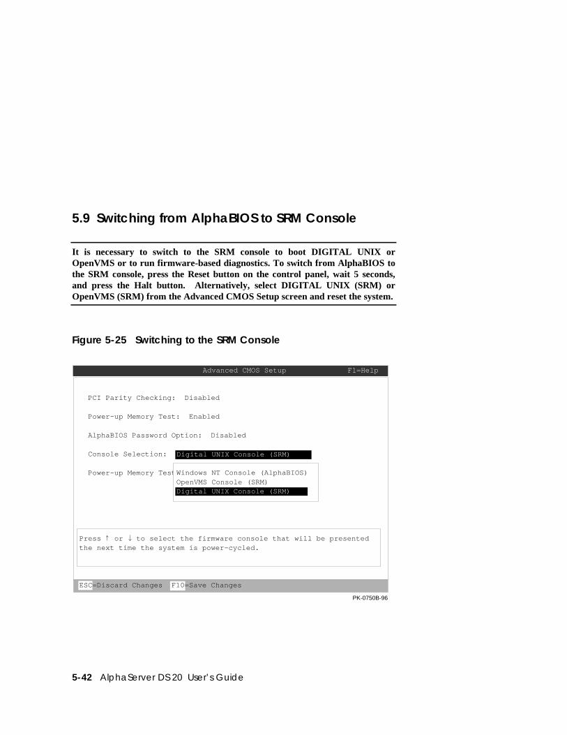
5-42 AlphaServer DS 20 User’s Guide
5.9 Switching from AlphaBIOS to SRM Console
It is necessary to switch to the SRM console to boot DIGITAL UNIX orOpenVMS or to run firmware-based diagnostics. To switch from AlphaBIOS tothe SRM console, press the Reset button on the control panel, wait 5 seconds,and press the Halt button. Alternatively, select DIGITAL UNIX (SRM) orOpenVMS (SRM) from the Advanced CMOS Setup screen and reset the system.
Figure 5-25 Switching to the SRM Console
PCI Parity Checking: Disabled
Power-up Memory Test: Enabled
AlphaBIOS Password Option: Disabled
Console Selection:
Power-up Memory Test Length: Full
Advanced CMOS Setup F1=Help
Digital UNIX Console (SRM)
Press or to select the firmware console that will be presentedthe next time the system is power-cycled.
ESC=Discard Changes F10=Save Changes
PK-0750B-96
Digital UNIX Console (SRM)
Windows NT Console (AlphaBIOS)OpenVMS Console (SRM)
AlphaBIOS Console 5-43
DIGITAL UNIX and OpenVMS are booted and firmware-based diagnostics are runfrom the SRM console. Follow this procedure to switch from AlphaBIOS to SRM:
1. Select CMOS Setup and press Enter.
2. In the CMOS Setup screen press F6. The Advanced CMOS Setup screen isdisplayed.
3. Select DIGITAL UNIX console (SRM) or OpenVMS console (SRM) andpress F10.
4. The CMOS Setup screen is displayed. Press F10 to save the change.
5. Reset the system.
Alternatively, you can press the Reset button, wait 5 seconds, and then press the Haltbutton.
The method you choose depends on how you want the system to function onsubsequent resets:
• If you make the selection in the Advanced CMOS Setup screen, the system willstop in the SRM console whenever it is powered up, reset, or initialized until theWindows NT operating system is again specified.
• If you press the Reset button, followed by the Halt button, no system setupinformation is changed, and AlphaBIOS will start the next time the system ispowered up, reset, or initialized.
To return to the AlphaBIOS console, issue the alphabios or nt command at the SRMconsole prompt.
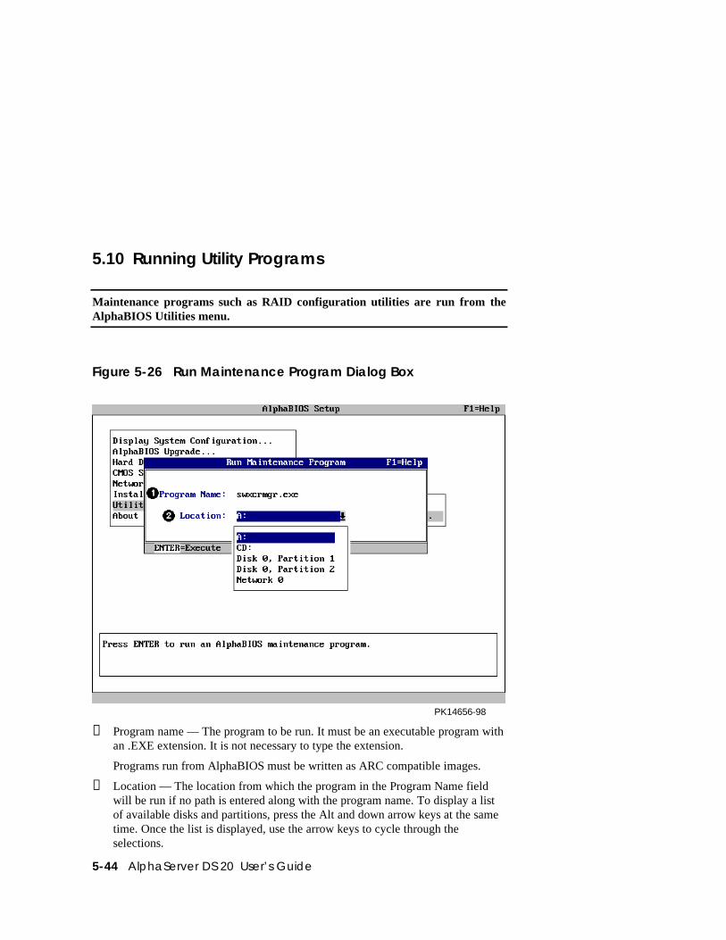
5-44 AlphaServer DS 20 User’s Guide
5.10 Running Utility Programs
Maintenance programs such as RAID configuration utilities are run from theAlphaBIOS Utilities menu.
Figure 5-26 Run Maintenance Program Dialog Box
PK14656-98
➊ Program name — The program to be run. It must be an executable program withan .EXE extension. It is not necessary to type the extension.
Programs run from AlphaBIOS must be written as ARC compatible images.
➋ Location — The location from which the program in the Program Name fieldwill be run if no path is entered along with the program name. To display a listof available disks and partitions, press the Alt and down arrow keys at the sametime. Once the list is displayed, use the arrow keys to cycle through theselections.
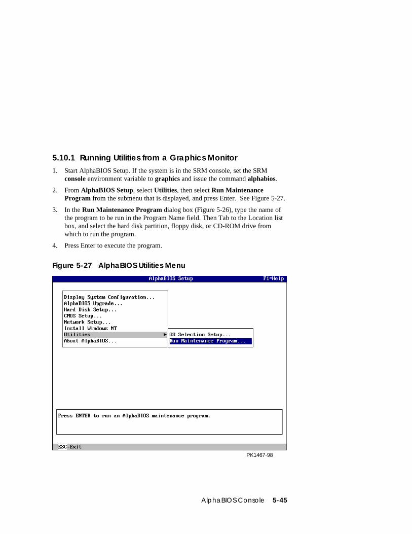
AlphaBIOS Console 5-45
5.10.1 Running Utilities from a Graphics Monitor1. Start AlphaBIOS Setup. If the system is in the SRM console, set the SRM
console environment variable to graphics and issue the command alphabios.
2. From AlphaBIOS Setup, select Utilities, then select Run MaintenanceProgram from the submenu that is displayed, and press Enter. See Figure 5-27.
3. In the Run Maintenance Program dialog box (Figure 5-26), type the name ofthe program to be run in the Program Name field. Then Tab to the Location listbox, and select the hard disk partition, floppy disk, or CD-ROM drive fromwhich to run the program.
4. Press Enter to execute the program.
Figure 5-27 AlphaBIOS Utilities Menu
PK1467-98
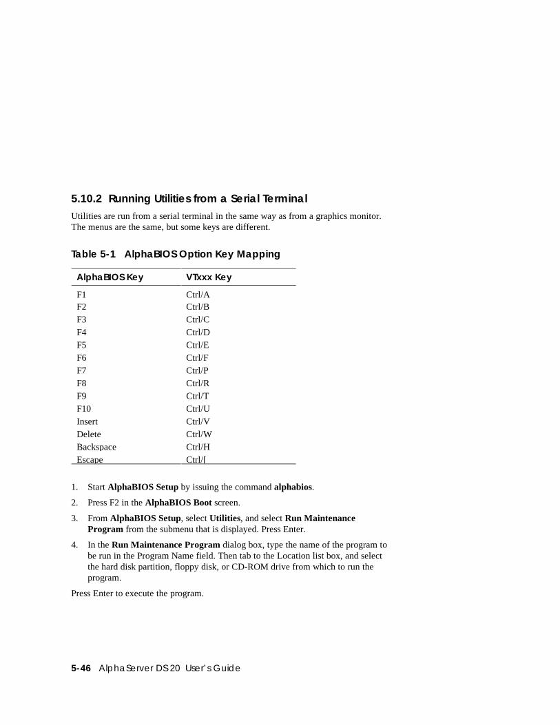
5-46 AlphaServer DS 20 User’s Guide
5.10.2 Running Utilities from a Serial TerminalUtilities are run from a serial terminal in the same way as from a graphics monitor.The menus are the same, but some keys are different.
Table 5-1 AlphaBIOS Option Key Mapping
AlphaBIOS Key VTxxx Key
F1 Ctrl/AF2 Ctrl/BF3 Ctrl/CF4 Ctrl/DF5 Ctrl/EF6 Ctrl/FF7 Ctrl/PF8 Ctrl/RF9 Ctrl/TF10 Ctrl/UInsert Ctrl/VDelete Ctrl/WBackspace Ctrl/HEscape Ctrl/[
1. Start AlphaBIOS Setup by issuing the command alphabios.
2. Press F2 in the AlphaBIOS Boot screen.
3. From AlphaBIOS Setup, select Utilities, and select Run MaintenanceProgram from the submenu that is displayed. Press Enter.
4. In the Run Maintenance Program dialog box, type the name of the program tobe run in the Program Name field. Then tab to the Location list box, and selectthe hard disk partition, floppy disk, or CD-ROM drive from which to run theprogram.
Press Enter to execute the program.
Managing the System Remotely 6-1
Chapter 6
Managing the System Remotely
This chapter describes how to manage the system from a remote location using theRemote Console Manager (RCM). You can use the RCM from a console terminal ata remote location or from a local console terminal connected to the COM1 port.
Sections in this chapter are:
• RCM Overview
• First-Time Setup
• RCM Commands
• Using the RCM Switchpack
• Troubleshooting Guide
• Modem Dialog Details
6-2 AlphaServer DS20 User’s Guide
6.1 RCM Overview
The remote console manager (RCM) monitors and controls the system remotely.The control logic resides on the system board.
The RCM is a separate console from the SRM and AlphaBIOS consoles. The SRMand AlphaBIOS firmware reside on the system board. The RCM firmware resides onthe server feature module and can only be accessed through COM 1. The RCM isrun from a serial console terminal or terminal emulator. A command interface letsyou reset, halt, and power the system on or off, regardless of the state of theoperating system or hardware. You can also use RCM to monitor system power andtemperature.
You can invoke the RCM either remotely or through the local serial consoleterminal. Once in RCM command mode, you can enter commands to control andmonitor the system. Only one RCM session can be active at a time.
• To connect to the RCM remotely, you dial in through a modem, enter apassword, and then type an escape sequence that invokes RCM command mode.You must set up the modem before you can dial in remotely.
• To connect to the RCM locally, the console terminal has to be connected toCOM 1 and then you type the escape sequence at the SRM console prompt onthe local serial console terminal to enter RCM mode.
CAUTION: Do not issue RCM commands until the system has powered up. If youenter certain RCM commands during power-up or reset, the system may hang. Inthat case you would have to disconnect the power cord at the power outlet. You can,however, use the RCM halt command during power-up to force a halt assertion.Refer to Section 3.12 for information on halt assertion.
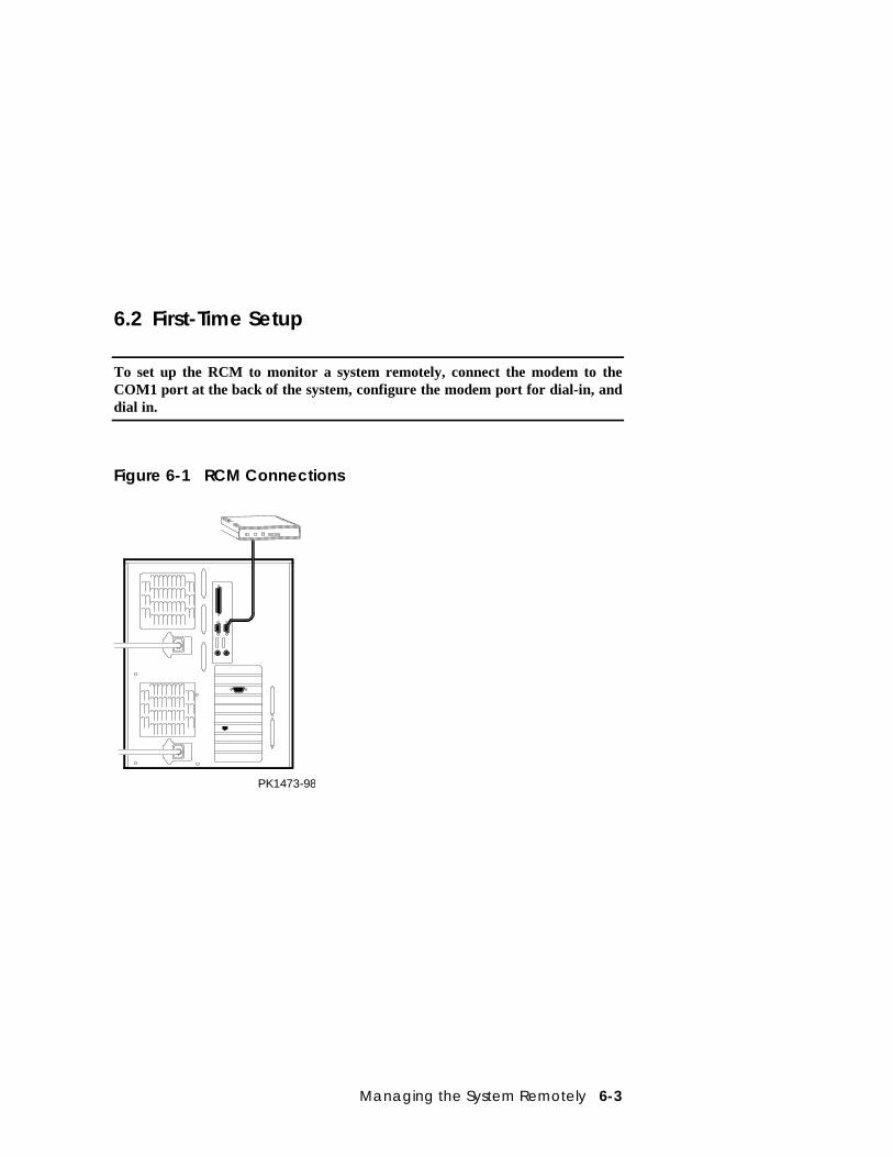
Managing the System Remotely 6-3
6.2 First-Time Setup
To set up the RCM to monitor a system remotely, connect the modem to theCOM1 port at the back of the system, configure the modem port for dial-in, anddial in.
Figure 6-1 RCM Connections
PK1473-98
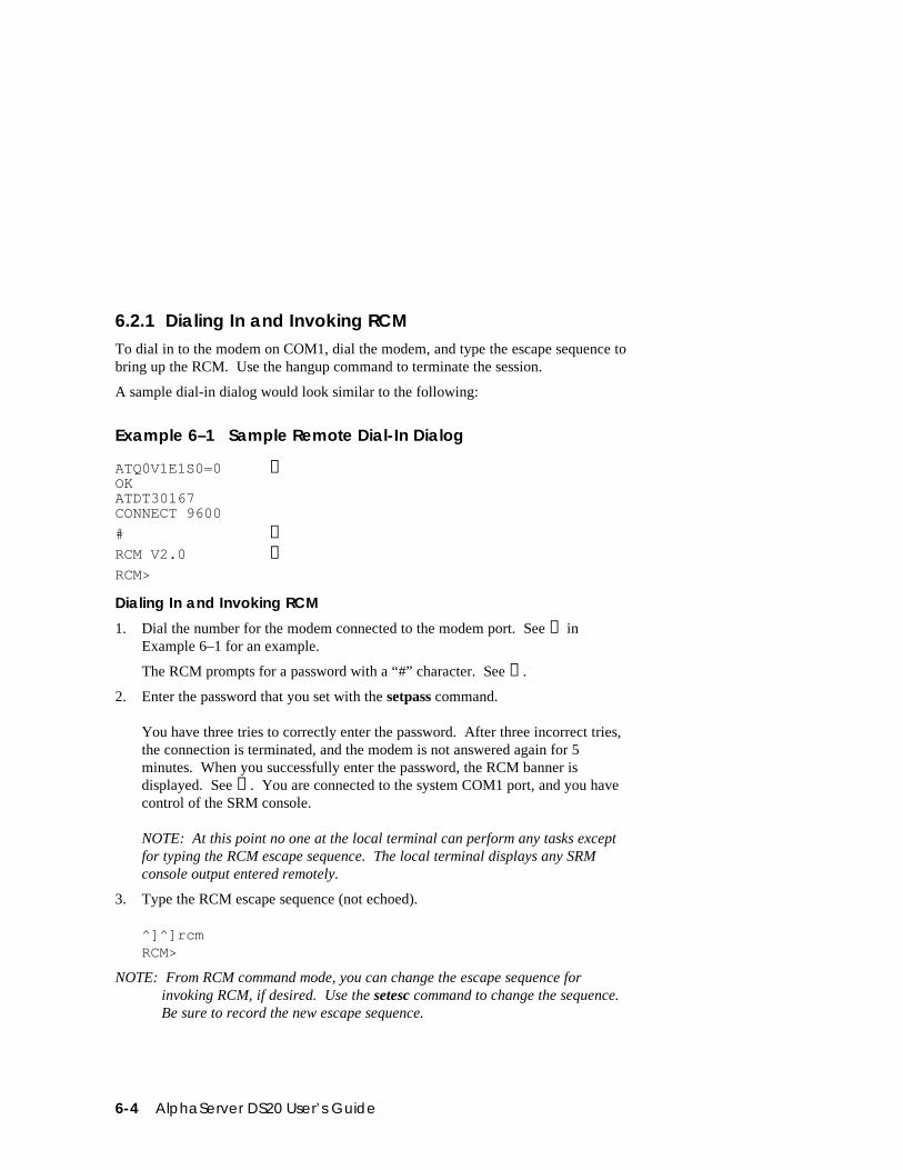
6-4 AlphaServer DS20 User’s Guide
6.2.1 Dialing In and Invoking RCMTo dial in to the modem on COM1, dial the modem, and type the escape sequence tobring up the RCM. Use the hangup command to terminate the session.
A sample dial-in dialog would look similar to the following:
Example 6–1 Sample Remote Dial-In Dialog
ATQ0V1E1S0=0OKATDT30167CONNECT 9600
➊
# ➋RCM V2.0 ➌RCM>
Dialing In and Invoking RCM
1. Dial the number for the modem connected to the modem port. See ➊ inExample 6–1 for an example.
The RCM prompts for a password with a “#” character. See ➋.
2. Enter the password that you set with the setpass command.
You have three tries to correctly enter the password. After three incorrect tries,the connection is terminated, and the modem is not answered again for 5minutes. When you successfully enter the password, the RCM banner isdisplayed. See ➌. You are connected to the system COM1 port, and you havecontrol of the SRM console.
NOTE: At this point no one at the local terminal can perform any tasks exceptfor typing the RCM escape sequence. The local terminal displays any SRMconsole output entered remotely.
3. Type the RCM escape sequence (not echoed).
^]^]rcmRCM>
NOTE: From RCM command mode, you can change the escape sequence forinvoking RCM, if desired. Use the setesc command to change the sequence.Be sure to record the new escape sequence.
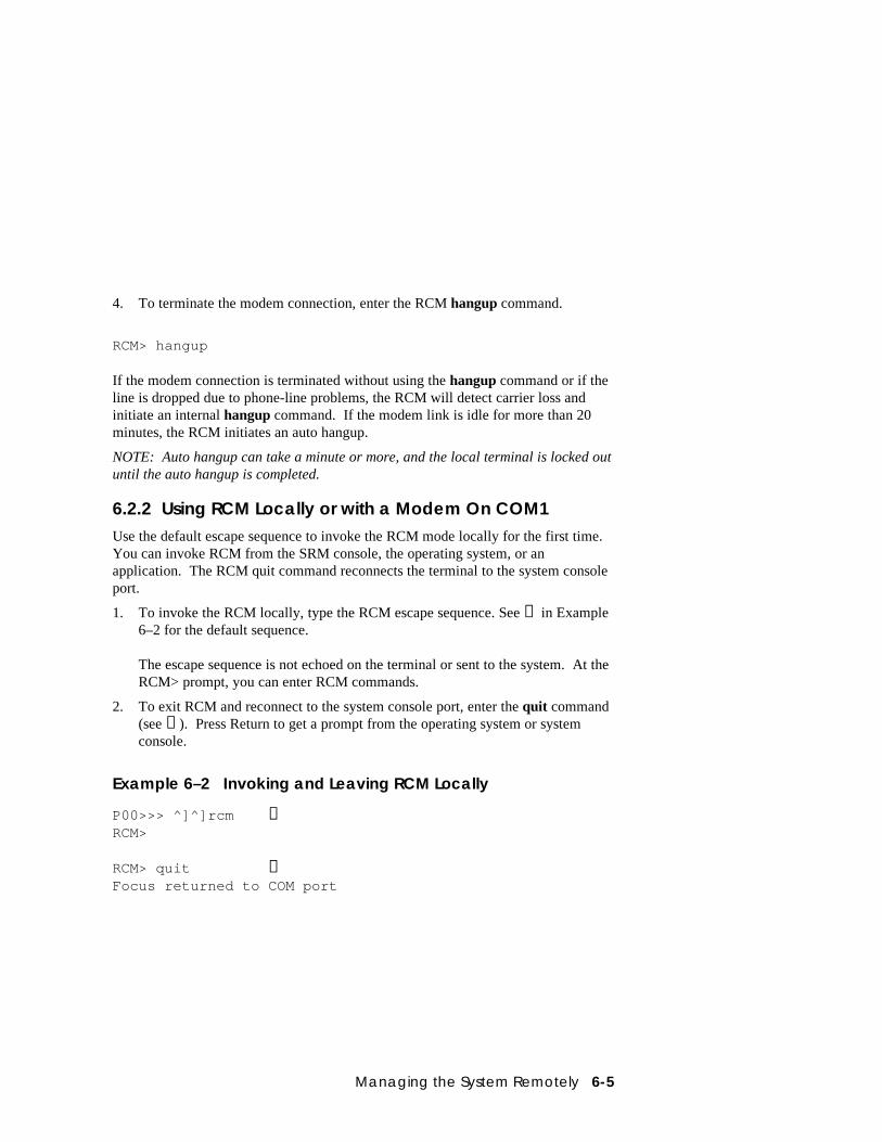
Managing the System Remotely 6-5
4. To terminate the modem connection, enter the RCM hangup command.
RCM> hangup If the modem connection is terminated without using the hangup command or if theline is dropped due to phone-line problems, the RCM will detect carrier loss andinitiate an internal hangup command. If the modem link is idle for more than 20minutes, the RCM initiates an auto hangup.
NOTE: Auto hangup can take a minute or more, and the local terminal is locked outuntil the auto hangup is completed.
6.2.2 Using RCM Locally or with a Modem On COM1Use the default escape sequence to invoke the RCM mode locally for the first time.You can invoke RCM from the SRM console, the operating system, or anapplication. The RCM quit command reconnects the terminal to the system consoleport.
1. To invoke the RCM locally, type the RCM escape sequence. See ➊ in Example6–2 for the default sequence.
The escape sequence is not echoed on the terminal or sent to the system. At theRCM> prompt, you can enter RCM commands.
2. To exit RCM and reconnect to the system console port, enter the quit command(see ➋). Press Return to get a prompt from the operating system or systemconsole.
Example 6–2 Invoking and Leaving RCM Locally
P00>>> ^]^]rcm ➊RCM>
RCM> quit ➋Focus returned to COM port
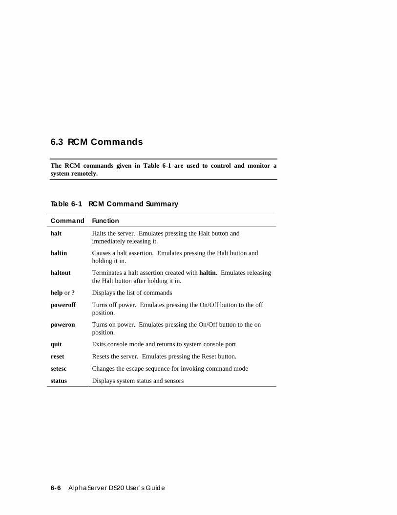
6-6 AlphaServer DS20 User’s Guide
6.3 RCM Commands
The RCM commands given in Table 6-1 are used to control and monitor asystem remotely.
Table 6-1 RCM Command Summary
Command Function
halt Halts the server. Emulates pressing the Halt button andimmediately releasing it.
haltin Causes a halt assertion. Emulates pressing the Halt button andholding it in.
haltout Terminates a halt assertion created with haltin. Emulates releasingthe Halt button after holding it in.
help or ? Displays the list of commands
poweroff Turns off power. Emulates pressing the On/Off button to the offposition.
poweron Turns on power. Emulates pressing the On/Off button to the onposition.
quit Exits console mode and returns to system console port
reset Resets the server. Emulates pressing the Reset button.
setesc Changes the escape sequence for invoking command mode
status Displays system status and sensors
Managing the System Remotely 6-7
Command Conventions
• The commands are not case sensitive.• A command must be entered in full.• You can delete an incorrect command with the Backspace key before you press
Enter.• If you type a valid RCM command, followed by extra characters, and press
Enter, the RCM accepts the correct command and ignores the extra characters.• If you type an incorrect command and press Enter, the command fails with the
message:
*** ERROR - unknown command ***
halt
The halt command halts the managed system. The halt command is equivalent topressing the Halt button on the control panel and then immediately releasing it. TheRCM firmware exits command mode and reconnects the user’s terminal to thesystem COM1 serial port.
RCM>haltFocus returned to COM port
The halt command can be used to force a halt assertion. See Section 3.12 forinformation on halt assertion.
NOTE: If you are running Windows NT, the halt command has no effect.
haltin
The haltin command halts a managed system and forces a halt assertion. The haltincommand is equivalent to pressing the Halt button on the control panel and holdingit in. This command can be used at any time after system power-up to allow you toperform system management tasks. See Section 3.12 for information on haltassertion.
NOTE: If you are running Windows NT, the haltin command does not affect theoperating system session, but it does cause a halt assertion.
haltout
The haltout command terminates a halt assertion that was done with the haltincommand. It is equivalent to releasing the Halt button on the control panel afterholding it in (rather than pressing it once and releasing it immediately). Thiscommand can be used at any time after system power-up. See Section 3.12 forinformation on halt assertion.
6-8 AlphaServer DS20 User’s Guide
help or ?
The help or ? command displays the RCM firmware commands.
poweroff
The poweroff command requests the RCM to power off the system. The poweroffcommand is equivalent to pressing the On/Off button on the control panel to the offposition.
RCM>poweroff
If the system is already powered off or if switch 3 (RPD DIS) on the switchpack hasbeen set to the on setting (disabled), this command has no immediate effect.
To power the system on again after using the poweroff command, you must issue thepoweron command.
If, for some reason, it is not possible to issue the poweron command, the localoperator can start the system as follows:
1. Press the On/Off button to the off position and disconnect the power cord.
2. Reconnect the power cord and press the On/Off button to the on position.
poweron
The poweron command requests the RCM to power on the system. The poweroncommand is equivalent to pressing the On/Off button on the control panel to the onposition. For the system power to come on, the following conditions must be met:
• AC power must be present at the power supply inputs.
• The On/Off button must be in the on position.
• All system interlocks must be set correctly.
The RCM exits command mode and reconnects the user’s terminal to the systemconsole port.
RCM>poweronFocus returned to COM port
NOTE: If the system is powered off with the On/Off button, the system will notpower up. The RCM will not override the “off” state of the On/Off button. If thesystem is already powered on, the poweron command has no effect.
Managing the System Remotely 6-9
quit
The quit command exits the user from command mode and reconnects the serialterminal to the system console port. The following message is displayed:
Focus returned to COM port
The next display depends on what the system was doing when the RCM wasinvoked. For example, if the RCM was invoked from the SRM console prompt, theconsole prompt will be displayed when you enter a carriage return. Or, if the RCMwas invoked from the operating system prompt, the operating system prompt will bedisplayed when you enter a carriage return.
reset
The reset command requests the RCM to reset the hardware. The reset command isequivalent to pressing the Reset button on the control panel.
RCM>resetFocus returned to COM port
The following events occur when the reset command is executed:
• The system restarts and the system console firmware reinitializes.
• The console exits RCM command mode and reconnects the serial terminal to thesystem COM1 serial port.
• The power-up messages are displayed, and then the console prompt is displayedor the operating system boot messages are displayed, depending on how thestartup sequence has been defined.
6-10 AlphaServer DS20 User’s Guide
setesc
The setesc command resets the default escape sequence for invoking RCM. Theescape sequence can be any character string. A typical sequence consists of 2 ormore characters, to a maximum of 15 characters. The escape sequence is stored inthe module’s on-board NVRAM.
NOTE: Be sure to record the new escape sequence. Although the factory defaultscan be restored if you forget the escape sequence, this requires resetting the ENRCM switch on the RCM switchpack.
The following sample escape sequence consists of 5 iterations of the Ctrl key and theletter “o”.
RCM>setesc^o^o^o^o^oRCM>
If the escape sequence entered exceeds 15 characters, the command fails with themessage:
*** ERROR ***
When changing the default escape sequence, avoid using special characters that areused by the system’s terminal emulator or applications.
Control characters are not echoed when entering the escape sequence. Use the statuscommand to verify the complete escape sequence.
status
The status command displays the current state of the system sensors, as well as thecurrent escape sequence and alarm information. The following is an example of thedisplay.
RCM>status
Firmware Rev: V2.0Escape Sequence: ^]^]RCMRemote Access: ENABLETemp (C): 26.0RCM Power Control: ONRCM Halt: DeassertedExternal Power: ONServer Power: ON
RCM>
The status fields are explained in Table 6-2.
Managing the System Remotely 6-11
Table 6-2 RCM Status Command Fields
Item Description
Firmware Rev: Revision of RCM firmware.
Escape Sequence: Current escape sequence to invoke RCM.
Remote Access: Modem remote access state. (ENABLE/DISABLE)
Temp (C): Current system temperature in degrees Celsius.
RCM Power Control: Current state of RCM system power control. (ON/OFF)
RCM Halt: Asserted indicates that halt has been asserted with thehaltin command. Deasserted indicates that halt hasbeen deasserted with the haltout command or bycycling power with the On/Off button on the controlpanel. The RCM Halt: field does not report haltscaused by pressing the Halt button.
External Power: Current state of power to RCM. Always on.
Server Power: Indicates whether power to the system is on or off.
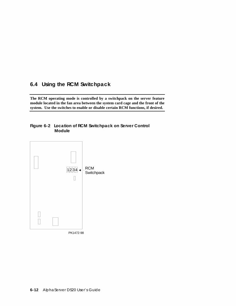
6-12 AlphaServer DS20 User’s Guide
6.4 Using the RCM Switchpack
The RCM operating mode is controlled by a switchpack on the server featuremodule located in the fan area between the system card cage and the front of thesystem. Use the switches to enable or disable certain RCM functions, if desired.
Figure 6-2 Location of RCM Switchpack on Server ControlModule
PK1472-98
12 34 RCMSwitchpack
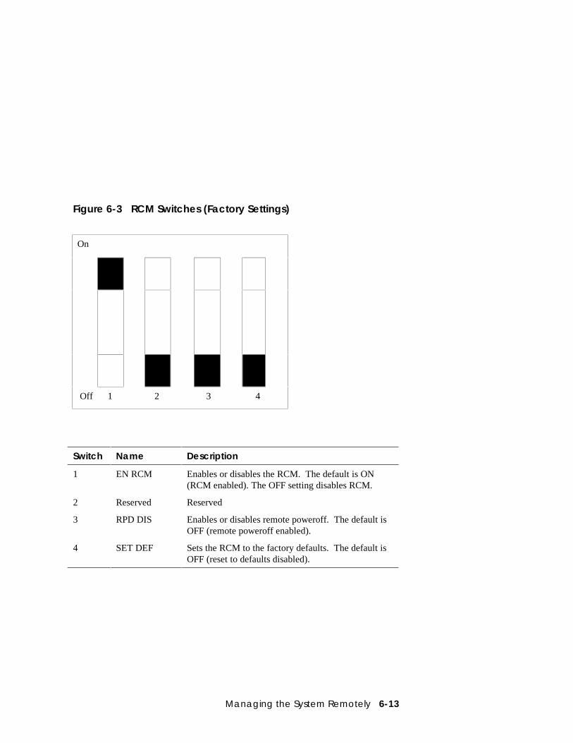
Managing the System Remotely 6-13
Figure 6-3 RCM Switches (Factory Settings)
On
Off 1 2 3 4
Switch Name Description
1 EN RCM Enables or disables the RCM. The default is ON(RCM enabled). The OFF setting disables RCM.
2 Reserved Reserved
3 RPD DIS Enables or disables remote poweroff. The default isOFF (remote poweroff enabled).
4 SET DEF Sets the RCM to the factory defaults. The default isOFF (reset to defaults disabled).
6-14 AlphaServer DS20 User’s Guide
Uses of the Switchpack
You can use the RCM switchpack to change the RCM operating mode or disable theRCM altogether. The following are conditions when you might want to change thefactory settings.
• Switch 1 (EN RCM)—Set this switch to OFF (disable) if you want to reset thebaud rate of the COM1 port to a value other than the system default of 9600.You must disable RCM to select a baud rate other than 9600.
• Switch 2 (Reserved) —Reserved.
• Switch 3 (RPD DIS). Set this switch to ON (disable) if you want to disable thepoweroff command. With poweroff disabled, the monitored system cannot bepowered down from the RCM.
• Switch 4 (SET DEF). Set this switch to ON (enable) if you want to reset theRCM to the factory settings. See the section “Resetting the RCM to FactoryDefaults.”
Changing a Switch Setting
The RCM switches are numbered on the server feature module. The defaultpositions are shown in Figure 6-3. To change a switch setting:
1. Turn off the system.
2. Unplug the AC power cords.
NOTE: If you do not unplug the power cords, the new setting will not take effectwhen you power up the system.
3. Remove the system covers. See Section 7.2.
4. Locate the RCM switchpack on the server feature module and change the switchsetting as desired.
5. Replace the system covers and plug in the power cords.
6. Power up the system to the SRM console prompt and type the escape sequenceto enter RCM command mode, if desired.
Managing the System Remotely 6-15
Resetting the RCM to Factory Defaults
You can reset the RCM to factory settings, if desired. You would need to do this ifyou forgot the escape sequence for the RCM. Follow the steps below.
1. Turn off the system.
2. Unplug the AC power cords.
NOTE: If you do not unplug the power cords, the reset will not take effect whenyou power up the system.
3. Remove the system covers. See Section 7.2.
4. Locate the RCM switchpack on the server feature module and set switch 4 toON.
5. Replace the system covers and plug in the power cords.
6. Power up the system to the SRM console prompt.
Powering up with switch 4 set to ON resets the escape sequence, password, andmodem enable states to the factory defaults.
7. Power down the system, unplug the AC power cords, and remove the systemcovers.
8. Set switch 4 to OFF.
9. Replace the system covers and plug in the power cords.
10. Power up the system to the SRM console prompt, and type the default escapesequence to invoke RCM command mode:
^]^]RCM
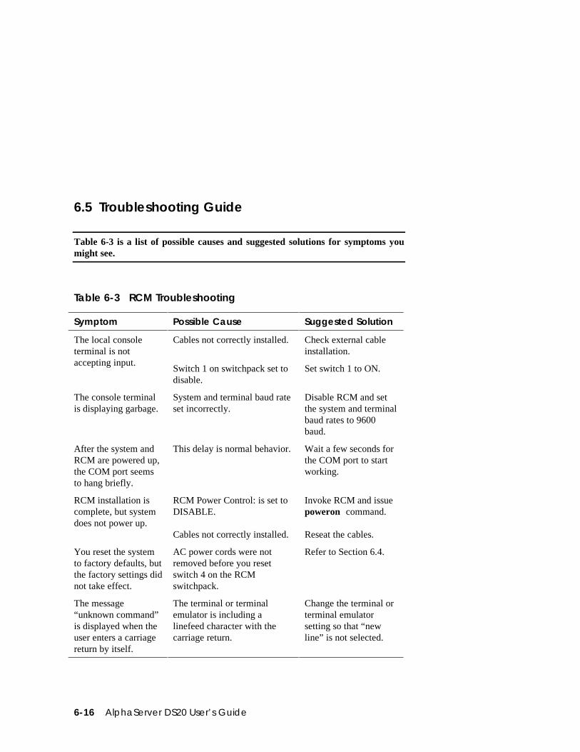
6-16 AlphaServer DS20 User’s Guide
6.5 Troubleshooting Guide
Table 6-3 is a list of possible causes and suggested solutions for symptoms youmight see.
Table 6-3 RCM Troubleshooting
Symptom Possible Cause Suggested Solution
The local consoleterminal is notaccepting input.
Cables not correctly installed.
Switch 1 on switchpack set todisable.
Check external cableinstallation.
Set switch 1 to ON.
The console terminalis displaying garbage.
System and terminal baud rateset incorrectly.
Disable RCM and setthe system and terminalbaud rates to 9600baud.
After the system andRCM are powered up,the COM port seemsto hang briefly.
This delay is normal behavior. Wait a few seconds forthe COM port to startworking.
RCM installation iscomplete, but systemdoes not power up.
RCM Power Control: is set toDISABLE.
Cables not correctly installed.
Invoke RCM and issuepoweron command.
Reseat the cables.
You reset the systemto factory defaults, butthe factory settings didnot take effect.
AC power cords were notremoved before you resetswitch 4 on the RCMswitchpack.
Refer to Section 6.4.
The message“unknown command”is displayed when theuser enters a carriagereturn by itself.
The terminal or terminalemulator is including alinefeed character with thecarriage return.
Change the terminal orterminal emulatorsetting so that “newline” is not selected.
Managing the System Remotely 6-17
6.6 Modem Dialog Details
This section is intended to help you reprogram your modem if necessary.
Default Initialization and Answer Strings
The modem initialization and answer command strings set at the factory for theRCM are:
Initialization string: AT&F0EVS0=0S12=50<cr>
Answer string ATXA<cr>
NOTE: All modem commands must be terminated with a <cr> character (0x0dhex).
Modifying Initialization and Answer Strings
The initialization and answer strings are stored in the RCM’s NVRAM. They comepre-programmed to support a wide selection of modems. With some modems,however, you may need to modify the initialization string, answer string, or both.The following SRM set and show commands are provided for this purpose.
To replace the initialization string:
P00>>> set rcm_init “new_init_string”
To replace the answer string:
P00>>> set rcm_answer “new_answer_string”
To display all the RCM strings that can be set by the user:
P00>>> show rcm*rcm_answer ATXArcm_dialoutrcm_init AT&F0EVS0=0S12=50P00>>>
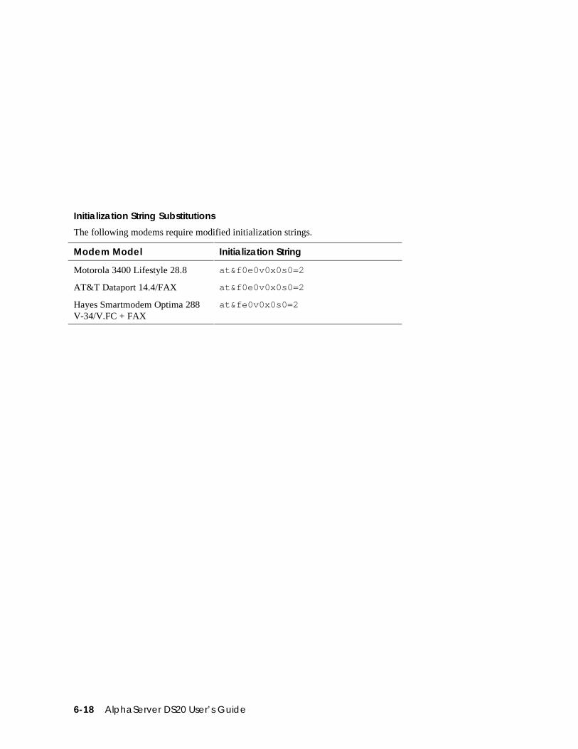
6-18 AlphaServer DS20 User’s Guide
Initialization String Substitutions
The following modems require modified initialization strings.
Modem Model Initialization String
Motorola 3400 Lifestyle 28.8 at&f0e0v0x0s0=2
AT&T Dataport 14.4/FAX at&f0e0v0x0s0=2
Hayes Smartmodem Optima 288V-34/V.FC + FAX
at&fe0v0x0s0=2
Installing Components 7-1
Chapter 7
Installing Components
This chapter provides system component removal and replacement procedures.Sections include:
• Preparing to Install or Remove Components
• Top Cover and Side Panel Removal and Replacement
• Installing a CPU Module
• Installing a Memory DIMM Option
• Installing a PCI or ISA Card
CAUTION: Be sure to follow the appropriate antistatic precautions wheneverhandling internal components.
7-2 AlphaServer DS20 User’s Guide
7.1 Preparing to Install or Remove Components
To prepare your system for installation and removal of components, you willneed to assemble the required equipment, familiarize yourself with antistaticprecautions, and remove the top and side panels of the system unit.
Required Equipment
You need the following equipment to perform the installation and removalprocedures described in the following sections:
• Flat-head screwdriver
• Phillips screwdriver
• Antistatic wrist strap
• Replacement option board kit or device kit, if necessary
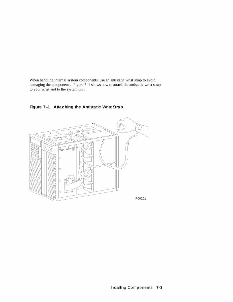
Installing Components 7-3
When handling internal system components, use an antistatic wrist strap to avoiddamaging the components. Figure 7–1 shows how to attach the antistatic wrist strapto your wrist and to the system unit.
Figure 7–1 Attaching the Antistatic Wrist Strap
IP00201
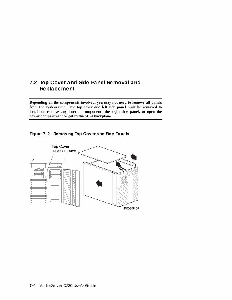
7-4 AlphaServer DS20 User’s Guide
7.2 Top Cover and Side Panel Removal andReplacement
Depending on the components involved, you may not need to remove all panelsfrom the system unit. The top cover and left side panel must be removed toinstall or remove any internal component; the right side panel, to open thepower compartment or get to the SCSI backplane.
Figure 7–2 Removing Top Cover and Side Panels
Top CoverRelease Latch
IP00205-97
Installing Components 7-5
Top Cover and Side Panel Removal
CAUTION: Make sure the system unit On/Off button is in the "off" position beforeremoving the system cover and panels.
To remove the top cover and side panels, refer to Figure 7–2 and follow these steps:
1. Shut down the operating system following the instructions listed in the operatingsystem documentation.
2. Press the On/Off switches on all external options connected to the system to theoff position.
3. Press the On/Off button on the system unit to the off position. An interlockingsensor switch inside the system unit will automatically turn off the system if youremove the top cover and have not turned off the system.
4. Turn the front door lock to the right to unlock the door.
5. Pull down the top cover release latch on the front of the system until it catchesin the down position.
6. Grasp the finger groove at the rear of the top cover and pull the top coverstraight back no farther than 2 inches, and lift up on the cover.
7. Pull the top of the side panel back, then up and away from the unit to remove it.(Repeat this step for the other panel.)
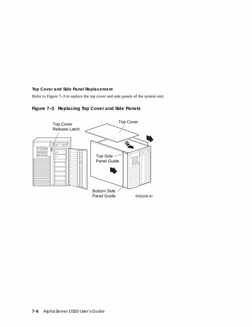
7-6 AlphaServer DS20 User’s Guide
Top Cover and Side Panel Replacement
Refer to Figure 7–3 to replace the top cover and side panels of the system unit.
Figure 7–3 Replacing Top Cover and Side Panels
Top CoverRelease Latch
IP00206-97
Top Cover
Top SidePanel Guide
Bottom SidePanel Guide
Installing Components 7-7
1. Align the guides on the top and bottom inside of the side panel with the lip ofthe system unit frame.
2. Tilt the side panel top toward the unit and lift the flange at the top of the panelover the system unit frame.
3. Slide the panel forward into position. (Repeat steps 1 to 3 for the other panel.)
4. Align the top cover with the top of the side panels and slide the cover gentlyonto the unit from the rear.
CAUTION: The top cover has a tab on the underside. Make sure to place thistab in the area immediately behind the microswitch. Do not hit the microswitchwith the tab.
5. Hold down the top cover release latch until the top cover is in place, and thenrelease it to secure the cover and panels.
6. Lock the door to secure the top cover and side panels.
7. Set the On/Off switches on all external options connected to the system to the onposition.
8. Press the On/Off button on the system unit to the on position.
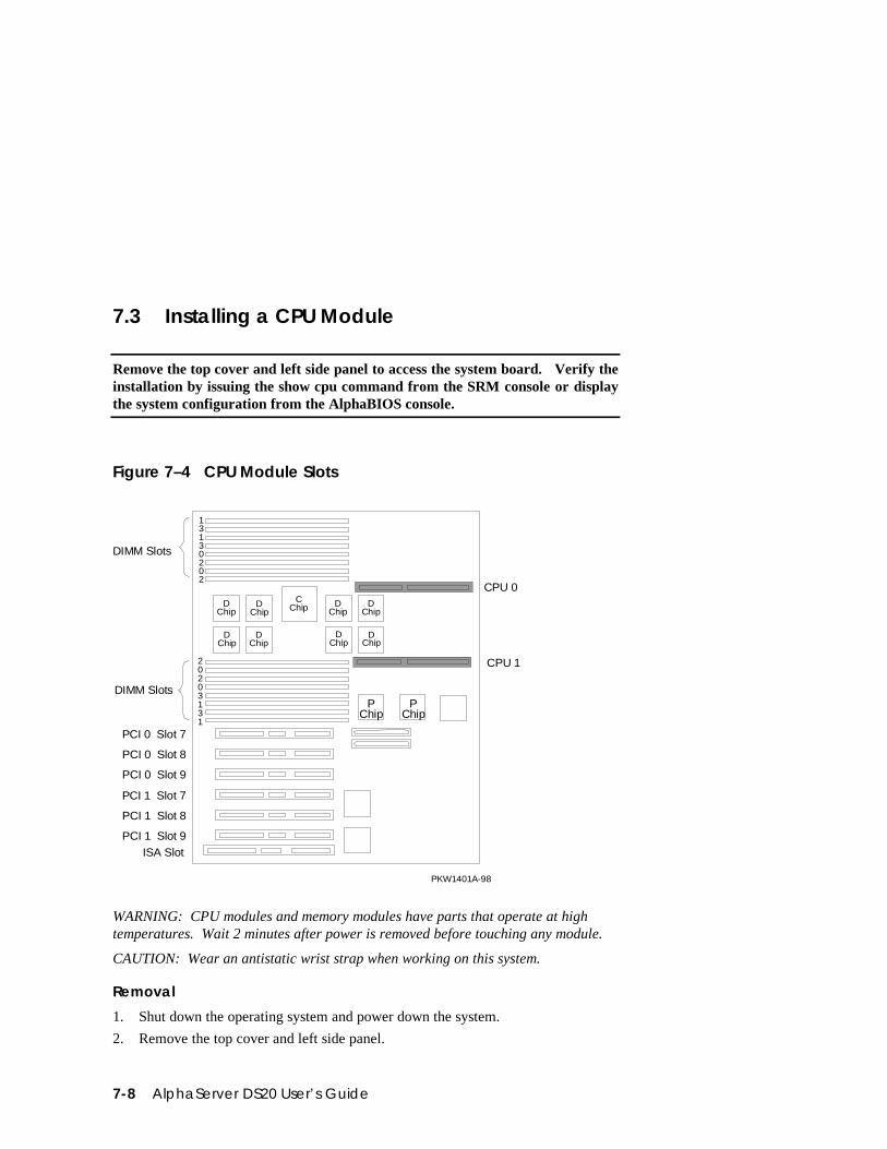
7-8 AlphaServer DS20 User’s Guide
7.3 Installing a CPU Module
Remove the top cover and left side panel to access the system board. Verify theinstallation by issuing the show cpu command from the SRM console or displaythe system configuration from the AlphaBIOS console.
Figure 7–4 CPU Module Slots
CPU 0
CPU 1
CChip
DChip
DChip
DChip
DChip
DChip
DChip
DChip
DChip
PChip
PChip
PKW1401A-98
0
0
1
1
2
2
3
3
0
0
1
1
2
2
3
3
PCI 0 Slot 7
PCI 0 Slot 8
PCI 0 Slot 9
PCI 1 Slot 7
PCI 1 Slot 8
PCI 1 Slot 9ISA Slot
DIMM Slots
DIMM Slots
WARNING: CPU modules and memory modules have parts that operate at hightemperatures. Wait 2 minutes after power is removed before touching any module.
CAUTION: Wear an antistatic wrist strap when working on this system.
Removal
1. Shut down the operating system and power down the system.
2. Remove the top cover and left side panel.
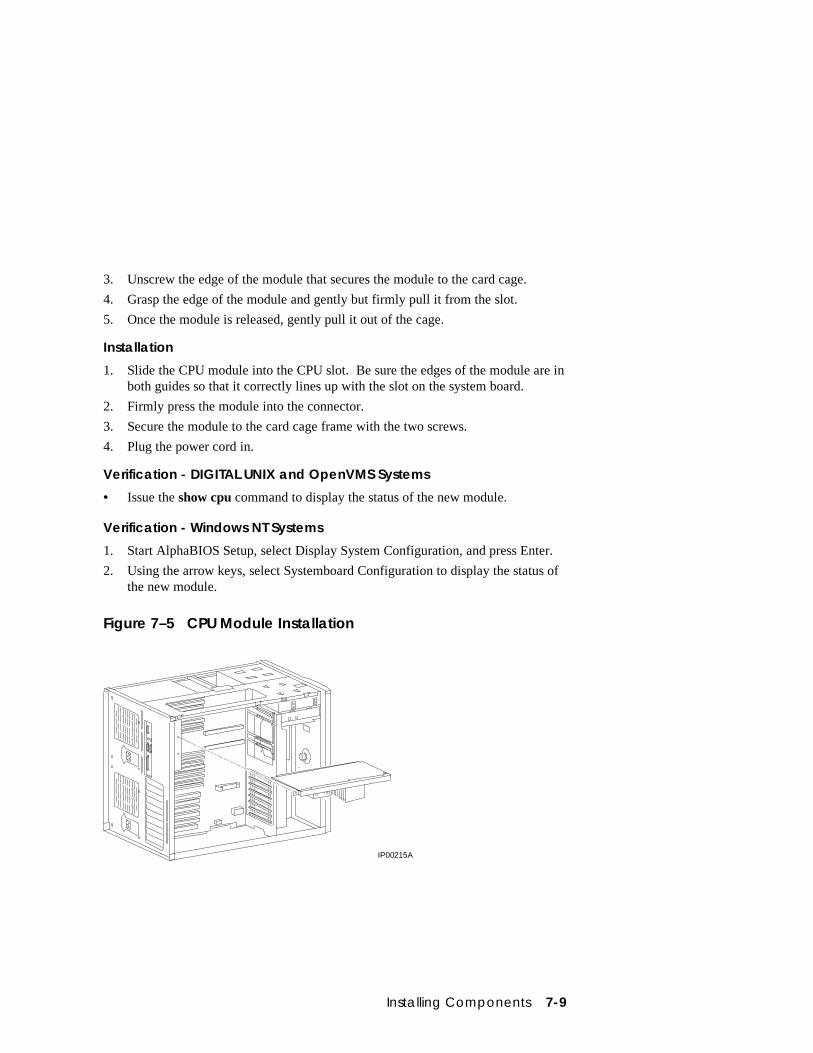
Installing Components 7-9
3. Unscrew the edge of the module that secures the module to the card cage.
4. Grasp the edge of the module and gently but firmly pull it from the slot.
5. Once the module is released, gently pull it out of the cage.
Installation
1. Slide the CPU module into the CPU slot. Be sure the edges of the module are inboth guides so that it correctly lines up with the slot on the system board.
2. Firmly press the module into the connector.
3. Secure the module to the card cage frame with the two screws.
4. Plug the power cord in.
Verification - DIGITAL UNIX and OpenVMS Systems
• Issue the show cpu command to display the status of the new module.
Verification - Windows NT Systems
1. Start AlphaBIOS Setup, select Display System Configuration, and press Enter.
2. Using the arrow keys, select Systemboard Configuration to display the status ofthe new module.
Figure 7–5 CPU Module Installation
IP00215A
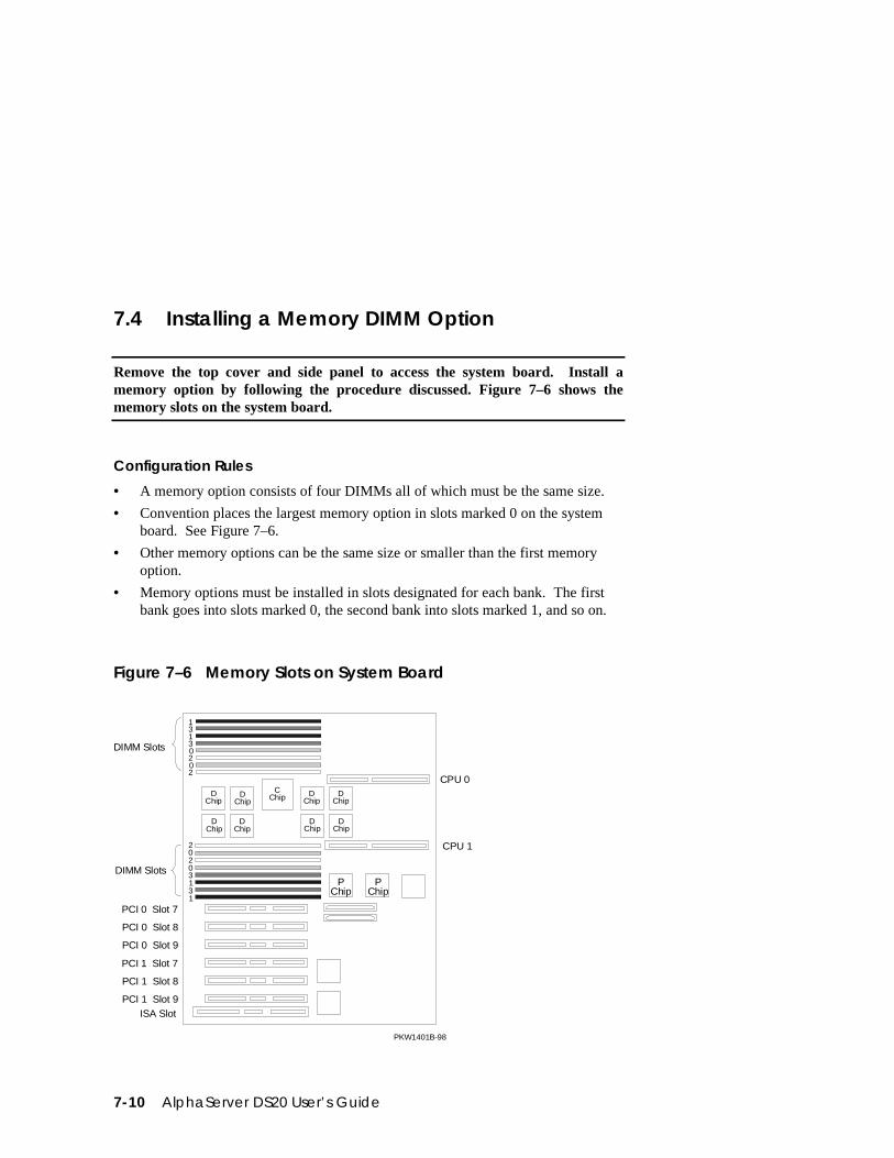
7-10 AlphaServer DS20 User’s Guide
7.4 Installing a Memory DIMM Option
Remove the top cover and side panel to access the system board. Install amemory option by following the procedure discussed. Figure 7–6 shows thememory slots on the system board.
Configuration Rules
• A memory option consists of four DIMMs all of which must be the same size.
• Convention places the largest memory option in slots marked 0 on the systemboard. See Figure 7–6.
• Other memory options can be the same size or smaller than the first memoryoption.
• Memory options must be installed in slots designated for each bank. The firstbank goes into slots marked 0, the second bank into slots marked 1, and so on.
Figure 7–6 Memory Slots on System Board
CPU 0
CPU 1
CChip
DChip
DChip
DChip
DChip
DChip
DChip
DChip
DChip
PChip
PChip
PKW1401B-98
2
20
03
31
1
2
20
0
3
3
1
1
PCI 0 Slot 7
PCI 0 Slot 8
PCI 0 Slot 9
PCI 1 Slot 7
PCI 1 Slot 8
PCI 1 Slot 9ISA Slot
DIMM Slots
DIMM Slots
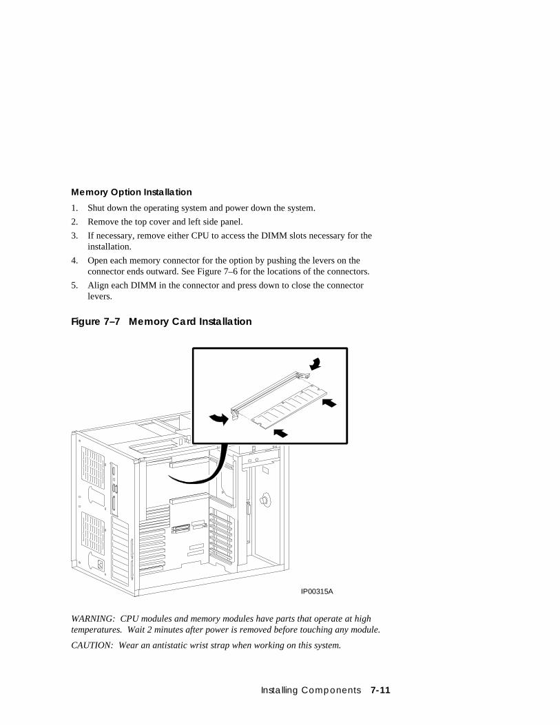
Installing Components 7-11
Memory Option Installation
1. Shut down the operating system and power down the system.
2. Remove the top cover and left side panel.
3. If necessary, remove either CPU to access the DIMM slots necessary for theinstallation.
4. Open each memory connector for the option by pushing the levers on theconnector ends outward. See Figure 7–6 for the locations of the connectors.
5. Align each DIMM in the connector and press down to close the connectorlevers.
Figure 7–7 Memory Card Installation
IP00315A
WARNING: CPU modules and memory modules have parts that operate at hightemperatures. Wait 2 minutes after power is removed before touching any module.
CAUTION: Wear an antistatic wrist strap when working on this system.
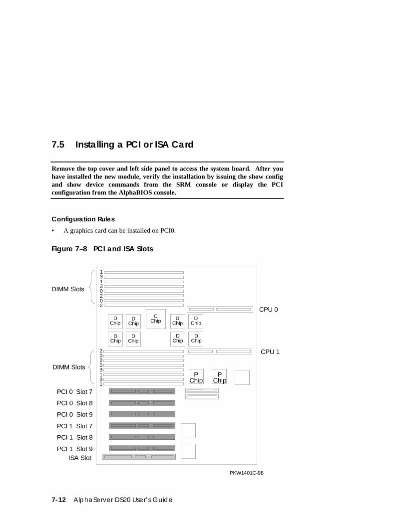
7-12 AlphaServer DS20 User’s Guide
7.5 Installing a PCI or ISA Card
Remove the top cover and left side panel to access the system board. After youhave installed the new module, verify the installation by issuing the show configand show device commands from the SRM console or display the PCIconfiguration from the AlphaBIOS console.
Configuration Rules
• A graphics card can be installed on PCI0.
Figure 7–8 PCI and ISA Slots
CPU 0
CPU 1
CChip
DChip
DChip
DChip
DChip
DChip
DChip
DChip
DChip
PChip
PChip
PKW1401C-98
0
0
1
1
2
2
3
3
0
0
1
1
2
2
3
3
PCI 0 Slot 7
PCI 0 Slot 8
PCI 0 Slot 9
PCI 1 Slot 7
PCI 1 Slot 8
PCI 1 Slot 9ISA Slot
DIMM Slots
DIMM Slots
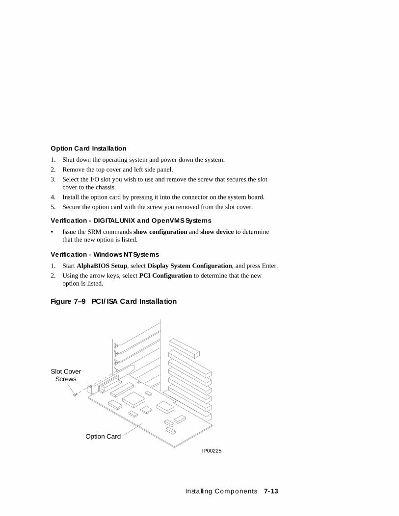
Installing Components 7-13
Option Card Installation
1. Shut down the operating system and power down the system.
2. Remove the top cover and left side panel.
3. Select the I/O slot you wish to use and remove the screw that secures the slotcover to the chassis.
4. Install the option card by pressing it into the connector on the system board.
5. Secure the option card with the screw you removed from the slot cover.
Verification - DIGITAL UNIX and OpenVMS Systems
• Issue the SRM commands show configuration and show device to determinethat the new option is listed.
Verification - Windows NT Systems
1. Start AlphaBIOS Setup, select Display System Configuration, and press Enter.
2. Using the arrow keys, select PCI Configuration to determine that the newoption is listed.
Figure 7–9 PCI/ISA Card Installation
Slot CoverScrews
Option Card
IP00225

Troubleshooting 8-1
Chapter 8
Troubleshooting
This chapter contains basic troubleshooting information. For more abouttroubleshooting, see the AlphaServer DS20 Service Manual.
Sections in this chapter are:
• System Does Not Power Up
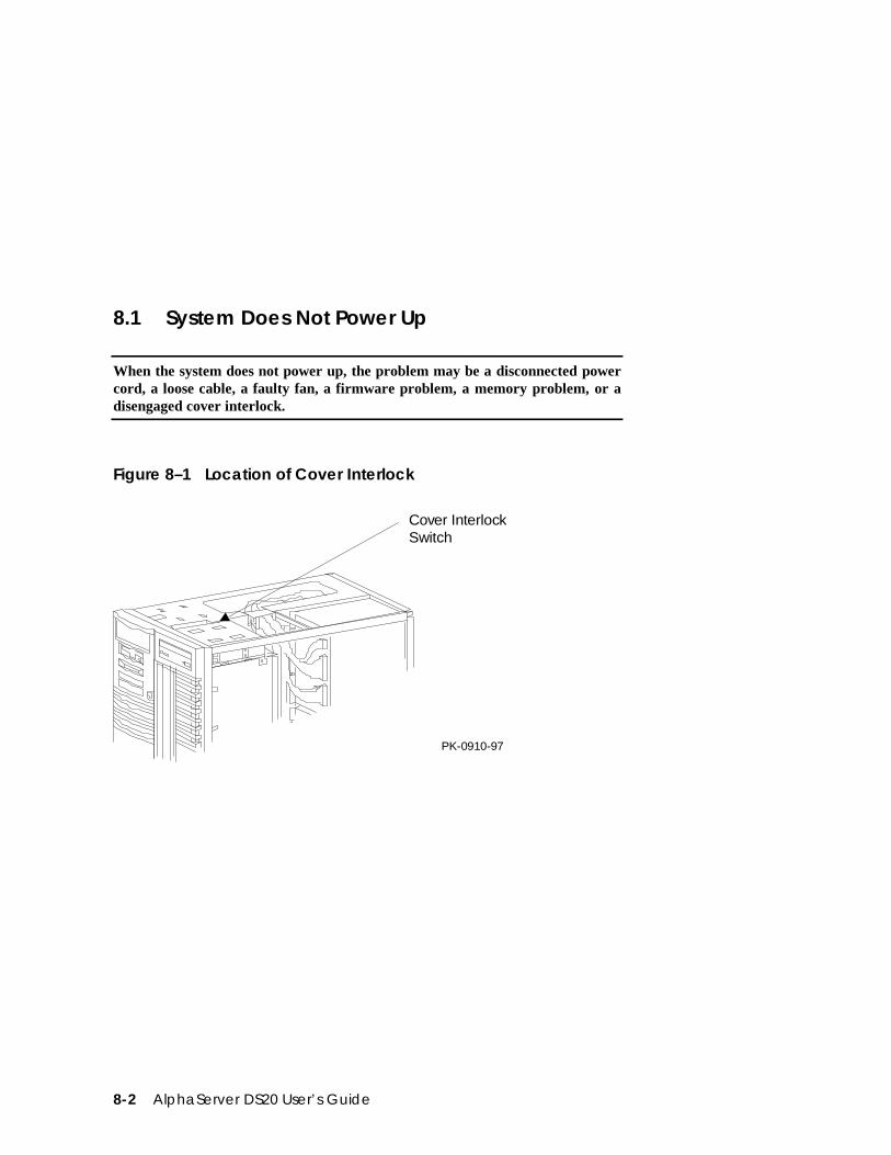
8-2 AlphaServer DS20 User’s Guide
8.1 System Does Not Power Up
When the system does not power up, the problem may be a disconnected powercord, a loose cable, a faulty fan, a firmware problem, a memory problem, or adisengaged cover interlock.
Figure 8–1 Location of Cover Interlock
Cover Interlock Switch
PK-0910-97
Troubleshooting 8-3
If the system does not power up
• Are the power cords plugged in?
• Are the cover and side panels closed and the interlock engaged?
The cover interlock must be engaged to enable power-up. See Figure 8–1 forthe interlock location.
If the system comes up and approximately 30 seconds later goesdown, possible failures are:
• CPU fan failure
• System fan failure
• Power supply fan failure
• Overtemperature condition
If you hear a single beep
A single beep indicates that the firmware in flash ROM is corrupt: The fail-safeloader will load and run immediately if you have a serial console terminal. Pressreset if you have a graphics console monitor. The following prompt will appear:
DP264>
Either place a floppy with the most recent firmware on it in the floppy drive (shouldhave come with the system) or place the AlphaServer Firmware CD-ROM in the CDdrive and at the prompt type:
DP264>fwupdate
Two things will happen:
• You will hear a single beep, followed by two beeps, followed by three beeps.
• And either
• UPD> will appear if you placed a floppy in the floppy drive
• Or AlphaBIOS will appear.
In either case refer to Section 3.9 and update the firmware.
If you hear four beeps
The header in the ROM is not valid, and the system will not boot.
If you hear six beeps
Six beeps indicate a checksum error occurred after the ROM image was copied intomemory. Either memory is misconfigured or a memory DIMM needs to be reseated.

SCSI Bus Configurations A-1
Appendix A
SCSI Bus Configurations
This appendix shows the possible configurations of the SCSI bus in the Storageworksshelf in the AlphaServer DS20 systems. The following topics are covered:
• Single-Bus Configuration
• Split-Bus Configuration
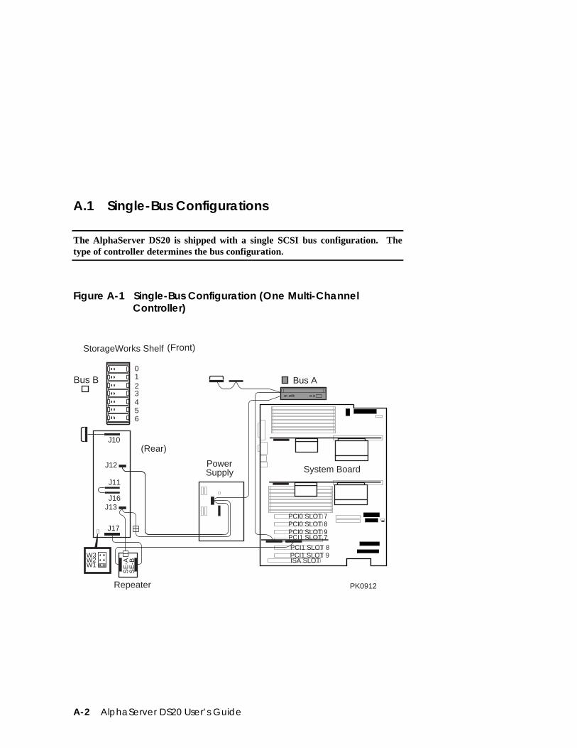
A-2 AlphaServer DS20 User’s Guide
A.1 Single-Bus Configurations
The AlphaServer DS20 is shipped with a single SCSI bus configuration. Thetype of controller determines the bus configuration.
Figure A-1 Single-Bus Configuration (One Multi-ChannelController)
J10
J12
J11
J16J13
J17
(Rear)
Repeater
W3W2W1
SE
-AS
E-B
System Board
23456
10
StorageWorks Shelf
Bus B
PCI0 SLOT 7PCI0 SLOT 8PCI0 SLOT 9
PCI1 SLOT 8PCI1 SLOT 9ISA SLOT
PCI1 SLOT 7
PowerSupply
Bus A
PK0912
(Front)
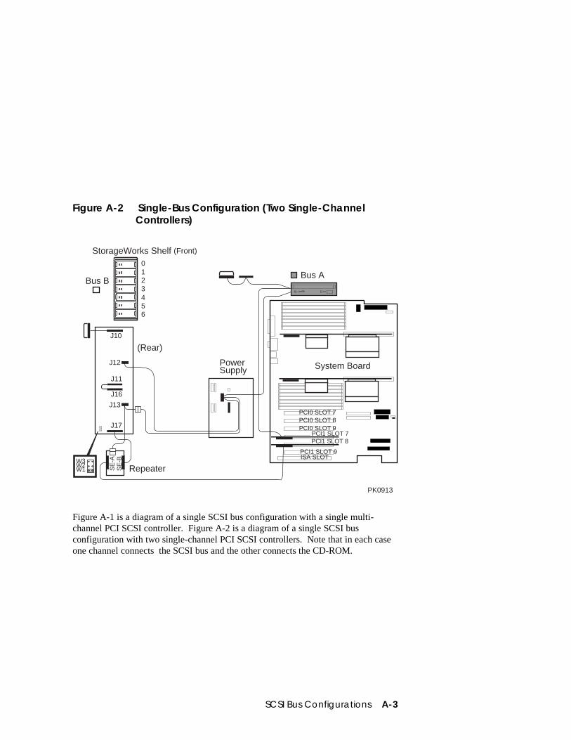
SCSI Bus Configurations A-3
Figure A-2 Single-Bus Configuration (Two Single-ChannelControllers)
PowerSupply System Board
Bus B
StorageWorks Shelf (Front)
Repeater
23456
10
PCI0 SLOT 7PCI0 SLOT 8PCI0 SLOT 9
PCI1 SLOT 9ISA SLOT
PCI1 SLOT 7
J10
J12
J11
J16
J13
J17
(Rear)
SE
-AS
E-B
PCI1 SLOT 8
Bus A
W3W2W1
PK0913
Figure A-1 is a diagram of a single SCSI bus configuration with a single multi-channel PCI SCSI controller. Figure A-2 is a diagram of a single SCSI busconfiguration with two single-channel PCI SCSI controllers. Note that in each caseone channel connects the SCSI bus and the other connects the CD-ROM.
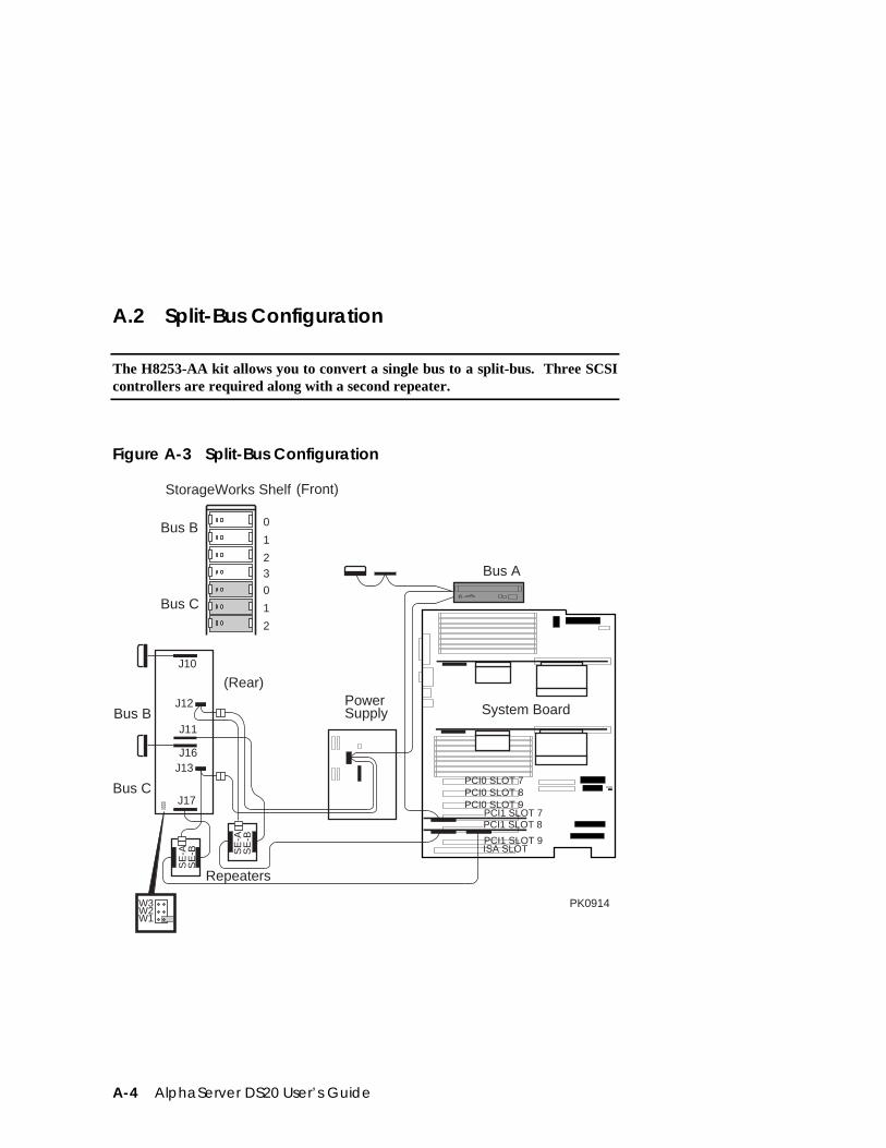
A-4 AlphaServer DS20 User’s Guide
A.2 Split-Bus Configuration
The H8253-AA kit allows you to convert a single bus to a split-bus. Three SCSIcontrollers are required along with a second repeater.
Figure A-3 Split-Bus Configuration
W3W2W1
PowerSupply System Board
StorageWorks Shelf
Repeaters
SE
-AS
E-B
PCI0 SLOT 7PCI0 SLOT 8PCI0 SLOT 9
PCI1 SLOT 9ISA SLOT
PCI1 SLOT 7
J10
J12
J11
J16J13
J17
(Rear)
SE
-AS
E-B
PCI1 SLOT 8
Bus A
PK0914
Bus B
Bus C
(Front)
23
0
1
2
1
0
Bus B
Bus C
Index-1
Index
?
? command, RCM · 6-8
A
Accessoriesidentifying · 2-5
Advanced CMOS setup screen,AlphaBIOS · 5-31
alphabios command, SRM · 4-3, 4-44AlphaBIOS console · 3-5, 5-2
boot screen · 3-20, 5-3checking PCI parity · 5-32displaying system configuration · 5-7enabling and disabling settings for
memory test · 5-32finding help · 5-5first-level help screen · 5-5key conventions · 5-5running in serial mode · 5-47second-level help screen · 5-6setting date and time · 5-30setting keyboard language · 5-30setting password · 5-32setup screen · 5-4starting · 5-3switching from SRM · 4-44switching to SRM · 5-32, 5-43
auto_action environment variable, SRM ·3-5, 4-45, 4-47
B
Baud rate, setting for COM* ports · 4-49boot command, SRM · 3-6, 3-7, 3-9, 3-11,
3-12, 3-13, 3-17, 3-19, 4-3, 4-17, 4-30passing information to command · 4-48using in secure mode · 4-25
Boot screen, AlphaBIOS · 3-20, 5-3boot_file environment variable, SRM · 3-7,
3-9, 3-13, 3-15, 3-17, 4-25boot_flags environment variable, SRM · 4-
25boot_osflags environment variable, SRM ·
3-7, 3-9, 3-13, 3-15, 3-17, 4-45, 4-48DIGITAL UNIX · 4-48OpenVMS · 4-48, 4-49
boot_reset environment variable, SRM · 3-13
bootdef_dev environment variable, SRM ·3-7, 3-9, 3-13, 3-15, 3-17, 4-25, 4-45
BootingDIGITAL UNIX · 3-6
from local disk · 3-6from remote disk · 3-8
OpenVMS · 3-12from cluster disk · 3-14from local disk · 3-12from remote disk · 3-16
passing information to command · 4-48Windows NT · 3-20
C
CD-ROM drive
Index-2
location · 1-12clear envar command, SRM · 4-3clear password command, SRM · 4-3, 4-28CMOS setup screen, AlphaBIOS · 5-29, 5-
31COM* ports, setting baud rate · 4-49com*_baud environment variable, SRM ·
4-45, 4-49Command syntax, SRM console · 4-5Configuring parameters, AlphaBIOS
console · 5-29Configuring the system
DIGITAL UNIX system · 4-19OpenVMS system · 4-19
ConsoleAlphaBIOS · 3-5specifying · 5-32SRM · 3-5, 4-1switching from AlphaBIOS to SRM · 5-
43switching from SRM to AlphaBIOS · 4-
44Console commands, SRM · 4-3Console environment variable, SRM · 4-
35, 4-45, 4-50Console subsystem · 1-3Console terminal · 1-10
specifying type · 4-50continue command, SRM · 4-3, 4-29, 4-30
using in secure mode · 4-25Control panel
specifying display message, SRM · 4-53Controls
front panel · 1-6Cover interlock · 8-2CPU module
enabling and disabling specificprocessors · 4-50
cpu_enabled environment variable, SRM ·4-45, 4-50
crash command, SRM · 4-3, 4-33Crash dump · 4-33
D
Date, setting in AlphaBIOS console · 5-30deposit command, SRM · 4-3, 4-37, 4-38Depositing data · 4-37Device naming conventions, SRM · 4-11DIGITAL UNIX
booting · 3-6from local disk · 3-6from remote disk · 3-8
console for · 4-1installing · 3-10, 3-11specifying as default operating system ·
4-53Diskette drive
location · 1-12display command, LFU · 3-40, 3-41Display system configuration screen,
AlphaBIOS console · 5-7Displaying system configuration · 4-8
AlphaBIOS console · 5-7Displaying the value or setting of an
environment variable · 4-35
E
edit command, SRM · 4-3, 4-36Environment variables, SRM · 4-34
auto_action · 3-5boot_file · 3-7, 3-9, 3-13, 3-15, 3-17, 4-
25boot_flags · 4-25boot_osflags · 3-7, 3-9, 3-13, 3-15, 3-17boot_reset · 3-13bootdef_dev · 3-7, 3-9, 3-13, 3-15, 3-17,
4-25displaying the value or setting · 4-35modifying · 4-35os_type · 3-5password · 4-28setting · 4-35summary · 4-45
Environmental requirements · 2-2
Index-3
Equipmentinstallation and removal · 7-2
Ethernet, specifying controller type · 4-51ew*0_mode environment variable, SRM ·
4-45, 4-51ew*0_protocols environment variable,
SRM · 4-45, 4-51examine command, SRM · 4-3, 4-37, 4-38Examining data · 4-37exit command, LFU · 3-25, 3-29, 3-35, 3-
39, 3-40, 3-41Expansion
system · 1-4
F
Finding helpAlphaBIOS console · 5-5SRM console · 4-43
FirmwareAlphaBIOS console · 5-2description · 1-3RCM · 6-6SRM console · 4-1updating · 3-24updating from AlphaBIOS · 5-21updating from CD-ROM · 3-26updating from floppy disk · 3-30, 3-32updating from network device · 3-36updating from SRM · 4-31updating, AlphaBIOS selection · 3-24updating, SRM command · 3-24
Formatting hard disk, AlphaBIOS · 5-23,5-25, 5-27
G
Graphics monitor, specifying as consoleterminal, SRM · 4-50
H
halt command, RCM · 6-7halt command, SRM · 4-3, 4-29, 4-30haltin command, RCM · 6-7haltout command, RCM · 6-7Hard disk configuration screen,
AlphaBIOS · 5-11Hard disk setup screen, AlphaBIOS · 5-23Hard disk, AlphaBIOS
creating and deleting partitions · 5-25error conditions · 3-43formatting a FAT partition · 5-27setting up · 5-23
HelpAlphaBIOS console · 5-5AlphaBIOS first-level help screen · 5-5AlphaBIOS second-level help screen ·
5-6help command, LFU · 3-40, 3-41help command, RCM · 6-8help command, SRM · 4-3, 4-43
I
Indicatorsfront panel · 1-6
Initialization and answer stringsdefault · 6-17modifying for modem · 6-17substitutions · 6-18
initialize command, SRM · 4-3, 4-16, 4-41,4-42
Initializing the system · 4-41Installing
DIGITAL UNIX · 3-10, 3-11OpenVMS · 3-18Windows NT · 3-22
Integrated peripherals screen, AlphaBIOS ·5-19
Interlock · 8-2Interlock switch · 7-5ISA options · 1-13
Index-4
isacnf command · 4-22
K
kbd_hardware_type environment variable,SRM · 4-35, 4-45, 4-52
Key conventionsAlphaBIOS console · 5-5
Key mapping, AlphaBIOS in serial mode ·5-47
Keyboardsetting language, AlphaBIOS · 5-30specifying hardware type, SRM · 4-52specifying layout, SRM · 4-52
L
language environment variable, SRM · 4-35, 4-45, 4-52
LFUstarting · 3-24, 3-25starting the utility · 3-24typical update procedure · 3-25updating firmware from CD-ROM · 3-
26updating firmware from floppy disk · 3-
30, 3-32updating firmware from network device
· 3-36lfu command, SRM · 3-25, 4-3, 4-30, 4-31LFU commands
display · 3-40, 3-41exit · 3-25, 3-29, 3-35, 3-39, 3-40, 3-41help · 3-40, 3-41lfu · 3-33, 3-35, 3-40, 3-41list · 3-25, 3-27, 3-33, 3-35, 3-37, 3-39,
3-40, 3-42readme · 3-40, 3-42summary · 3-40update · 3-25, 3-29, 3-40, 3-42verify · 3-40, 3-42
list command, LFU · 3-25, 3-27, 3-33, 3-37, 3-40, 3-42
Loadable Firmware Update utility · SeeLFU
login command, SRM · 4-3, 4-26using in secure mode · 4-25
M
Maintenance programs, AlphaBIOS · 5-45Memory configuration screen, AlphaBIOS
· 5-16Memory options · 1-13Memory test
enabling and disabling settings inAlphaBIOS · 5-32
Modemdial-in procedure · 6-4dialog details · 6-17using in RCM · 6-3
Modifying an environment variable, SRM ·4-35
more command, SRM · 4-4, 4-40
N
Naming conventions, SRM · 4-11Network protocols, enabling for booting
and other functions, SRM · 4-51
O
ocp_text environment variable, SRM · 4-35, 4-46, 4-53
OpenVMSbooting · 3-12
from cluster disk · 3-14from local disk · 3-12from remote disk · 3-16
console for · 4-1installing · 3-18specifying as default operating system ·
4-53Operating system
Index-5
booting DIGITAL UNIX · 3-6from local disk · 3-6from remote disk · 3-8
booting OpenVMS · 3-12from cluster disk · 3-14from local disk · 3-12from remote disk · 3-16
booting Windows NT · 3-20installing DIGITAL UNIX · 3-10, 3-11installing OpenVMS · 3-18installing Windows NT · 3-22, 5-33specifying default · 4-53
Operating system selection setup screen,AlphaBIOS · 5-39
Operating system selection, defined · 5-36Operating system selections screen,
AlphaBIOS · 5-35Operating systems
supported · 1-3switching between · 3-24
Operating the system remotely · 6-2Options
memory · 1-13ordering · 1-13storage · 1-12
os_type environment variable, SRM · 3-5,3-21, 4-35, 4-53, 5-32
P
Parameters, configuring in AlphaBIOSconsole · 5-29
password environment variable, SRM · 4-28
Password, setting in AlphaBIOS console ·5-32
PCIenabling and disabling parity checking
on bus, SRM · 4-54finding device information, AlphaBIOS
· 5-15parity checking in AlphaBIOS · 5-32slot numbers · 4-11
PCI configuration screen, AlphaBIOS · 5-13
PCI options · 1-13slot numbers · 4-11
pci_parity environment variable, SRM · 4-46, 4-54
pk*0_fast environment variable, SRM · 4-46, 4-54
pk*0_host_id environment variable, SRM ·4-46, 4-55
pk*0_soft_term environment variable,SRM · 4-46, 4-55
Powersystem does not power up · 8-2
Power requirements · 2-3poweroff command, RCM · 6-8poweron command, RCM · 6-8Power-up display · 3-4Power-up, specifying console action, SRM
· 4-47prcache command, SRM · 4-4, 4-21Primary operating system, AlphaBIOS · 5-
37Processor
enabling and disabling specific CPUs ·4-50
Q
quit command, RCM · 6-9
R
RCM · 6-2, 6-12changing settings on switchpack · 6-13command summary · 6-6invoking and leaving command mode ·
6-5modem dialog details · 6-17modem use · 6-3remote dial-in · 6-4resetting to factory defaults · 6-15switchpack defaults · 6-13
Index-6
switchpack location · 6-12troubleshooting · 6-16
RCM commands? · 6-8halt · 6-7haltin · 6-7haltout · 6-7help · 6-8poweroff · 6-8poweron · 6-8quit · 6-9reset · 6-9setesc · 6-10status · 6-10
Reading a file · 4-40readme command, LFU · 3-40, 3-42Reliability · 1-4Remote console manager · See RCMRemote dial-in, RCM · 6-4reset command, RCM · 6-9Reset, specifying console action, SRM · 4-
47Running maintenance programs,
AlphaBIOS · 5-45Running utility programs · 5-45
S
SCSIenabling and disabling terminators,
SRM · 4-55enabling Fast SCSI, SRM · 4-54setting controller host bus node ID,
SRM · 4-55SCSI bus configurations
single-bus · A-2, A-3split-bus · A-4
SCSI configuration screen, AlphaBIOS · 5-17
Security · 1-5Security lock · 2-8Serial terminal, specifying as console
terminal, SRM · 4-50
Server management · 1-5set envar command, SRM · 4-4, 4-34, 4-35set host command, SRM · 4-4, 4-19set password command, SRM · 4-4, 4-24set secure command, SRM · 4-4, 4-25setesc command, RCM · 6-10Setting an environment variable · 4-35Setting up the hard disk, AlphaBIOS · 5-23Setup screen, AlphaBIOS · 5-4show config command, SRM · 4-4, 4-8show cpu command, SRM · 4-9show device command, SRM · 3-6, 3-7, 3-
9, 3-12, 3-13, 3-15, 3-17, 4-4, 4-10, 4-30
show envar command, SRM · 3-12, 4-4, 4-34, 4-35
show memory command, SRM · 4-4, 4-12show pal command, SRM · 4-4, 4-12show power command, SRM · 4-4, 4-13show version command, SRM · 4-4, 4-14Side panels
removing · 7-5replacing · 7-6
Space requirements · 2-1Special characters, SRM console · 4-6SRM console · 3-5, 4-1–4-56
command syntax · 4-5device naming conventions · 4-11invoking · 4-2special characters · 4-6summary of commands · 4-3summary of environment variables · 4-
45switching from AlphaBIOS · 5-32, 5-43switching to AlphaBIOS · 4-44
SRM console commandsalphabios · 4-3, 4-44boot · 3-7, 3-9, 3-11, 3-13, 3-17, 3-19,
4-3, 4-17, 4-30using in secure mode · 4-25
clear envar · 4-3clear password · 4-3, 4-28continue · 4-3, 4-29, 4-30
using in secure mode · 4-25
Index-7
crash · 4-3, 4-33deposit · 4-3, 4-37, 4-38edit · 4-3, 4-36examine · 4-3, 4-37, 4-38halt · 4-3, 4-29, 4-30help · 4-3, 4-43initialize · 4-3, 4-16, 4-41, 4-42lfu · 3-25, 4-3, 4-30, 4-31login · 4-3, 4-26
using in secure mode · 4-25more · 4-4, 4-40prcache · 4-4, 4-21set envar · 4-4, 4-34, 4-35set host · 4-4, 4-19set password · 4-4, 4-24set secure · 4-4, 4-25show config · 4-4, 4-8show cpu · 4-9show device · 3-7, 3-9, 3-13, 3-15, 3-17,
4-4, 4-10, 4-30show envar · 4-4, 4-34, 4-35show memory · 4-4, 4-12show pal · 4-4, 4-12show power · 4-4, 4-13show version · 4-4, 4-14start · 4-29, 4-30
using in secure mode · 4-25stop · 4-4, 4-30summary of commands · 4-3test · 4-4, 4-22, 4-23, 4-30
SRM console environment variablesauto_action · 4-45, 4-47boot_osflags · 4-45, 4-48, 4-49boot_osflags, DIGITAL UNIX · 4-48boot_osflags, OpenVMS · 4-48bootdef_dev · 4-45com*_baud · 4-45, 4-49commands for displaying the value or
setting · 4-35commands for modifying · 4-35commands for setting · 4-35commands for using · 4-34console · 4-45, 4-50cpu_enabled · 4-45, 4-50
ew*0_mode · 4-45, 4-51ew*0_protocols · 4-45, 4-51kbd_hardware_type · 4-45, 4-52language · 4-45, 4-52ocp_text · 4-46, 4-53os_type · 3-21, 4-53, 5-32pci_parity · 4-46, 4-54pk*0_fast · 4-46, 4-54pk*0_host_id · 4-46, 4-55pk*0_soft_term · 4-46, 4-55tt_allow_login · 4-46, 4-56
SRM firmwareenabling and disabling login to · 4-56
Standard CMOS setup screen, AlphaBIOS· 5-29
start command, SRM · 4-29, 4-30using in secure mode · 4-25
Starting AlphaBIOS · 5-3Starting CPUs · 4-29status command, RCM · 6-10stop command, SRM · 4-4, 4-30Stopping CPUs · 4-29Storage options · 1-12Syntax
SRM console commands · 4-5System
does not power up · 8-2features · 1-2, 1-4
System board configuration screen,AlphaBIOS · 5-9
System configurationdisplaying in AlphaBIOS console · 5-7displaying in SRM console · 4-8
System crash dump · 4-33System failure, specifying console action,
SRM · 4-47
T
Terminal, console · 1-10test command, SRM · 4-4, 4-22, 4-23, 4-30Testing the system (all operating systems) ·
4-22
Index-8
Time, setting in AlphaBIOS console · 5-30Top cover
removing · 7-5Troubleshooting · 8-1tt_allow_login environment variable, SRM
· 4-46, 4-56
U
update command, LFU · 3-25, 3-29, 3-35,3-39, 3-40, 3-42
Updating firmwareAlphaBIOS console · 5-21from AlphaBIOS console · 3-24from SRM console · 3-24SRM console · 4-31
Utility programs · 5-45running from serial terminal (NT) · 5-47
V
verify command, LFU · 3-40, 3-42Version selection, Windows NT · 5-35
W
Windows NTauto start · 5-39booting · 3-20console for · 5-2designating primary operating system ·
5-37installing · 3-22, 5-33selecting version · 5-35specifying as default operating system ·
4-53starting automatically · 5-30, 5-39


![KK-DS20 E 4K.ps [ 1 ], page 9 @ Preflight ( DS20 E_KerbKonus )](https://img.pdfslide.us/doc/110x75/58587f7a1a28ab6e328ddd23/kk-ds20-e-4kps-1-page-9-preflight-ds20-ekerbkonus-.jpg)