Embed Size (px)
Citation preview

746-819-B0-001, Rev A (06/2017) 1
Alpha XMP-8D for PWE-3 and PWE-6 Installation InstructionsThe Alpha XMP-8D transformer module enables any XM2/XM3 power supply to provide localized 120VAC uninterruptible power, up to 250W, for devices such as Small Cell radios. The XMP-8D is also available with an optional selectable auxiliary power output (5Vdc or 12Vdc) up to 11W, intended to power an auxiliary device, such as a MetroE NID. The XMP-8D is powered from the 60/90V output of the XM2/XM3.
GND
N
9̃0V~
60V~
WARNINGDISCONNECT FROM XM
OUTPUT BEFORE SERVICING.AVERTISSEMENT
DÉCONNECTER DE LA SOURCED’ALIMENTATION DUTRANSFORMATEUR
XM AVANT DE PROCÉDERÀ LA MAINTENANCE.
®
VDC5 12
+ –
AUXILIARYOUTPUT
120VACOUTPUT
INPUTVOLTAGETAP SELECT
XMP-8D Layout
5 or 12VDC / 11W Output
5 or 12VDC Select Switch
AC Input Fuse6.25A, 250V, Slow-Blow
Side View
Front View
Equipment powered by XMP-8D should be located outside of the Alpha PWE enclosure using an Alpha-approved mounting bracket. Placing active powered equipment, e.g. Small Cell Radios inside the PWE cabinet may exceed the thermal design, resulting in premature failure of the Alpha Power Supply and batteries, in addition to the powered equipment itself. Alpha will not be liable for any damage to Alpha or 3rd party equipment caused by excess heat from non-approved configuration.
CAUTION!
(for XMP-8D-AUX only)
(for XMP-8D-AUX only)
The PWE Fan Kit (P/N: 745-101-20) is required for XMP installations where the XM3 total load (including the XMP) exceeds 15A.
CAUTION!
Do not operate the 5VDC/12VDC Auxiliary select switch while the device is powered on.
CAUTION!
2 746-819-B0-001, Rev A (06/2017)
Installing the Transformer
Alpha recommends installing the transformer in the space to the left of the power supply. If space is limited, place the transformer on it's right side on the power supply shelf (Fig. 1). If this space is not available, follow the instructions below for installing the transformer on top of the power supply.
Fig. 2, Mounting Clips
Alternate Method for Installing the Transformer
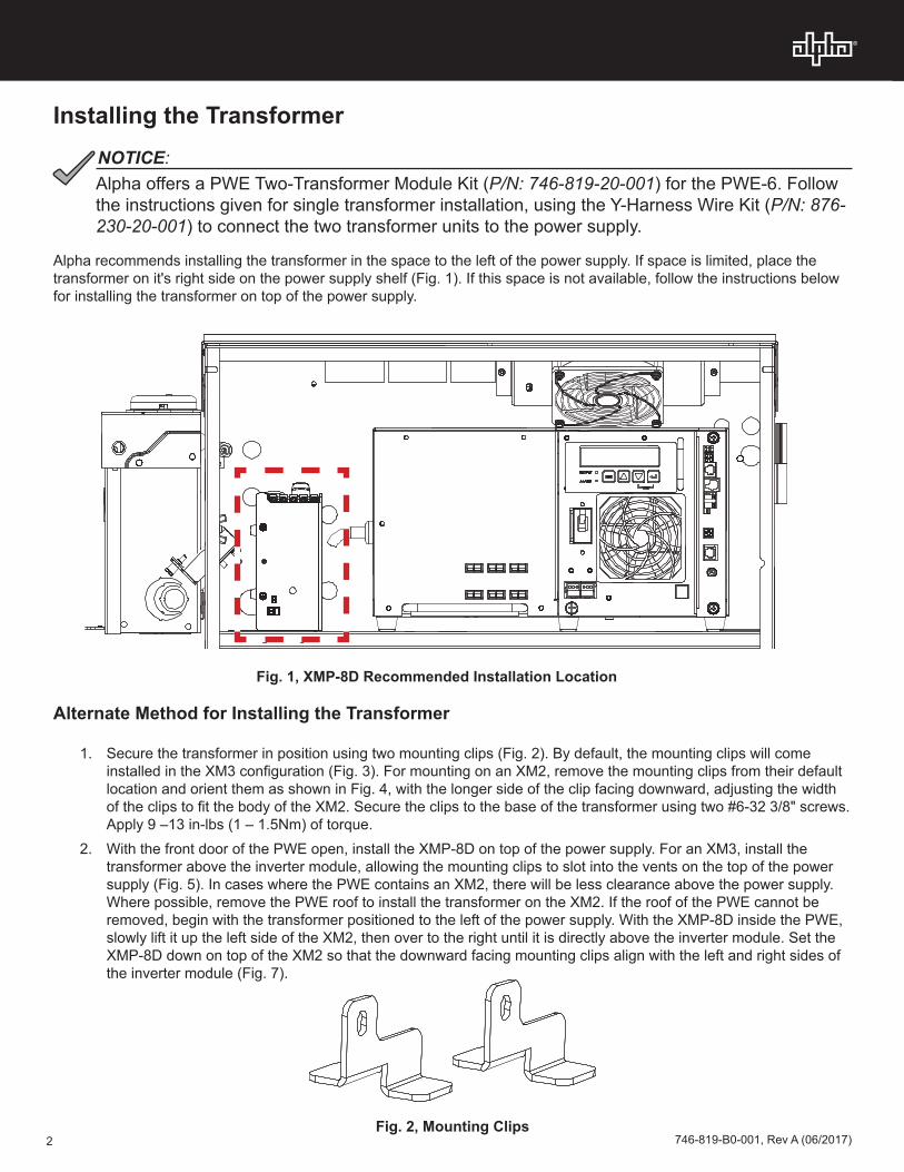
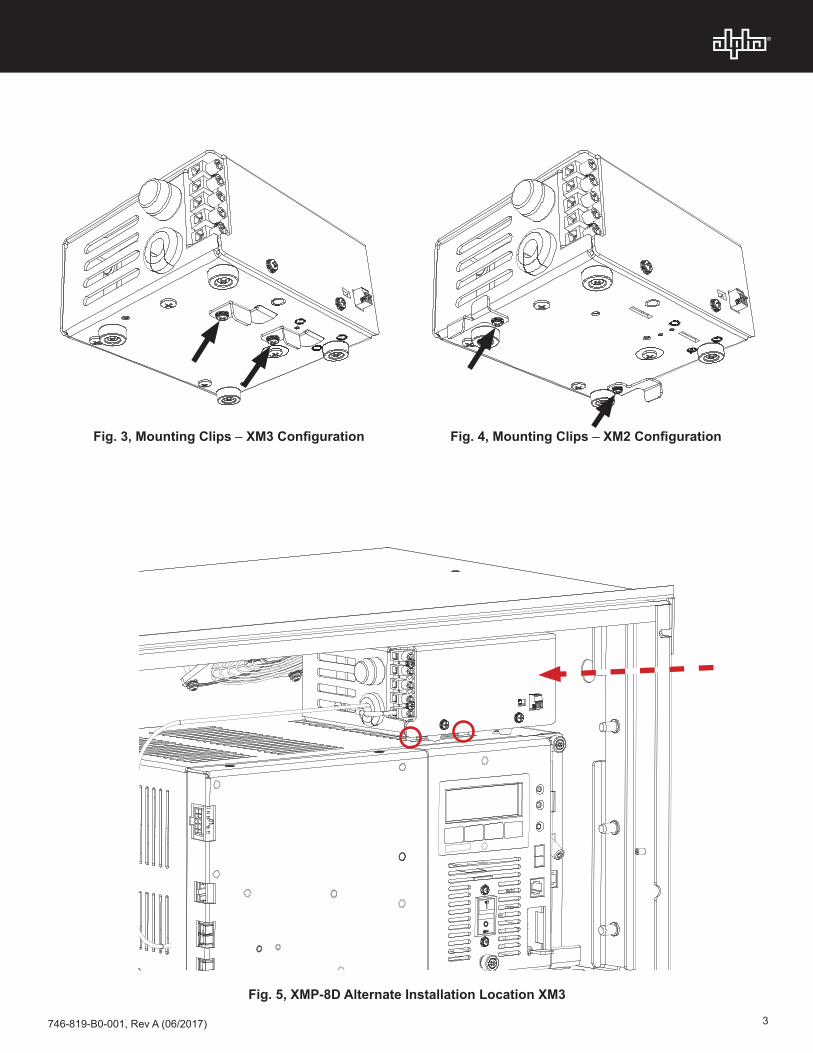
1. Secure the transformer in position using two mounting clips (Fig. 2). By default, the mounting clips will come installed in the XM3 configuration (Fig. 3). For mounting on an XM2, remove the mounting clips from their default location and orient them as shown in Fig. 4, with the longer side of the clip facing downward, adjusting the width of the clips to fit the body of the XM2. Secure the clips to the base of the transformer using two #6-32 3/8" screws. Apply 9 –13 in-lbs (1 – 1.5Nm) of torque.
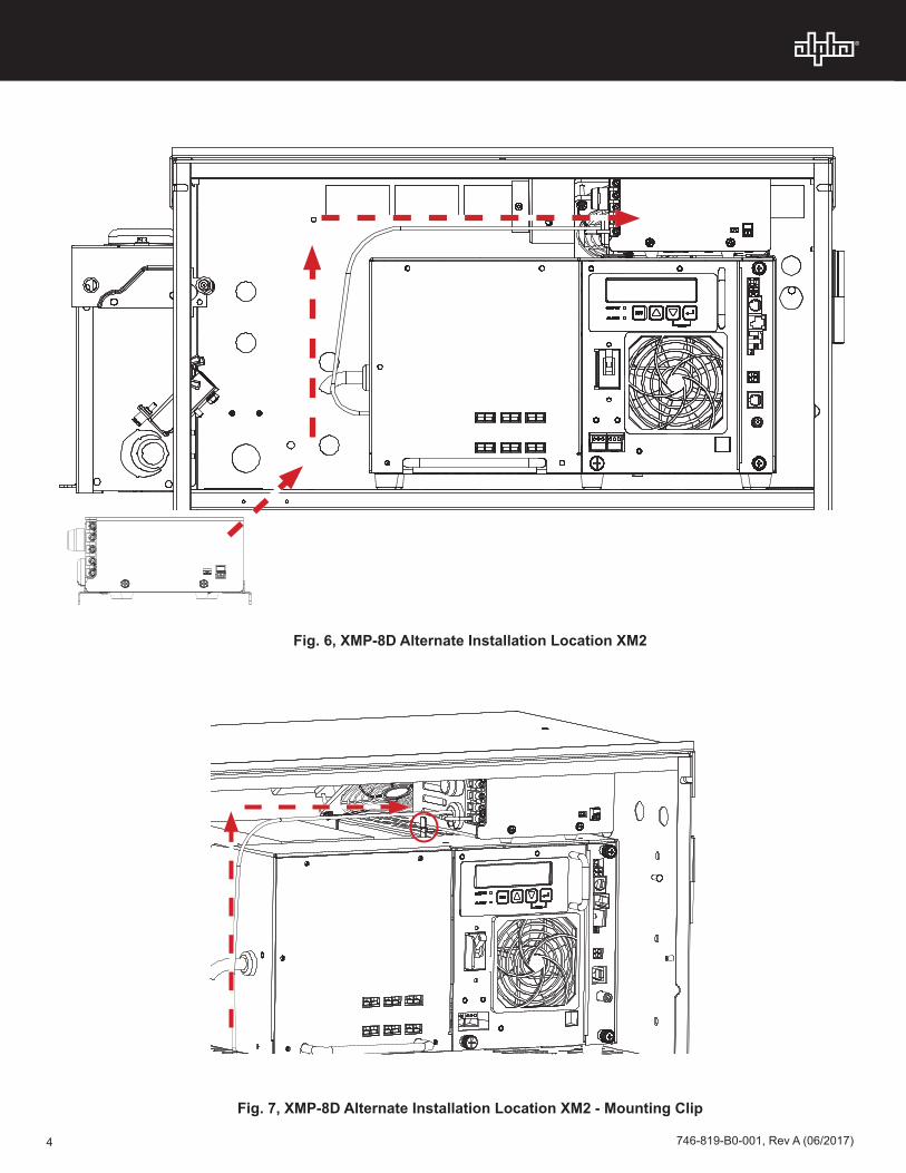
2. With the front door of the PWE open, install the XMP-8D on top of the power supply. For an XM3, install the transformer above the inverter module, allowing the mounting clips to slot into the vents on the top of the power supply (Fig. 5). In cases where the PWE contains an XM2, there will be less clearance above the power supply. Where possible, remove the PWE roof to install the transformer on the XM2. If the roof of the PWE cannot be removed, begin with the transformer positioned to the left of the power supply. With the XMP-8D inside the PWE, slowly lift it up the left side of the XM2, then over to the right until it is directly above the inverter module. Set the XMP-8D down on top of the XM2 so that the downward facing mounting clips align with the left and right sides of the inverter module (Fig. 7).
Fig. 1, XMP-8D Recommended Installation Location
Alpha offers a PWE Two-Transformer Module Kit (P/N: 746-819-20-001) for the PWE-6. Follow the instructions given for single transformer installation, using the Y-Harness Wire Kit (P/N: 876-230-20-001) to connect the two transformer units to the power supply.
NOTICE:
746-819-B0-001, Rev A (06/2017) 3
Fig. 3, Mounting Clips – XM3 Configuration Fig. 4, Mounting Clips – XM2 Configuration
Fig. 5, XMP-8D Alternate Installation Location XM3
4 746-819-B0-001, Rev A (06/2017)
Fig. 7, XMP-8D Alternate Installation Location XM2 - Mounting Clip
Fig. 6, XMP-8D Alternate Installation Location XM2

746-819-B0-001, Rev A (06/2017) 5
Connecting the Components
~N
OUTPUT 2
GND
Fig. 8, XMP-8D Alternate Installation XM3 - Front View
1. Determine power supply output voltage and set 60 / 90V jumper on XMP-8D terminal strip to match.2. Connect ground wire from XMP-8D to the cabinet ground stud. 3. Make auxilary power connections (if applicable). This may include:
• 5VDC or 12VDC Selection• Terminal Connections
4. Install connected device(s), e.g. Small Cell.5. Route power cables from connected device(s) to the transformer module terminal block.6. Attach the transformer module to XM2/XM3 output connector.
Ground Connection
Fig. 9, XMP-8D Connections
Alpha Technologies Alpha reserves the right to change specifications without notice.Alpha is a registered trademark of Alpha Technologies.
For more information visit www.alpha.com
© 2017 Alpha Technologies Inc. All Rights Reserved.
746-819-B0-001 Rev. A (06/2017)
Worldwide Corporate Offices
North AmericaTel: +1 360 647 2360Fax: +1 360 671 4936
EuropeTel: +49 9122 79889 0Fax: +49 9122 79889 21
Latin AmericaTel: +561 792.9651Fax: +561 792.7157
Asia PacificTel: +852 2736.8663Fax: +852 2199.7988
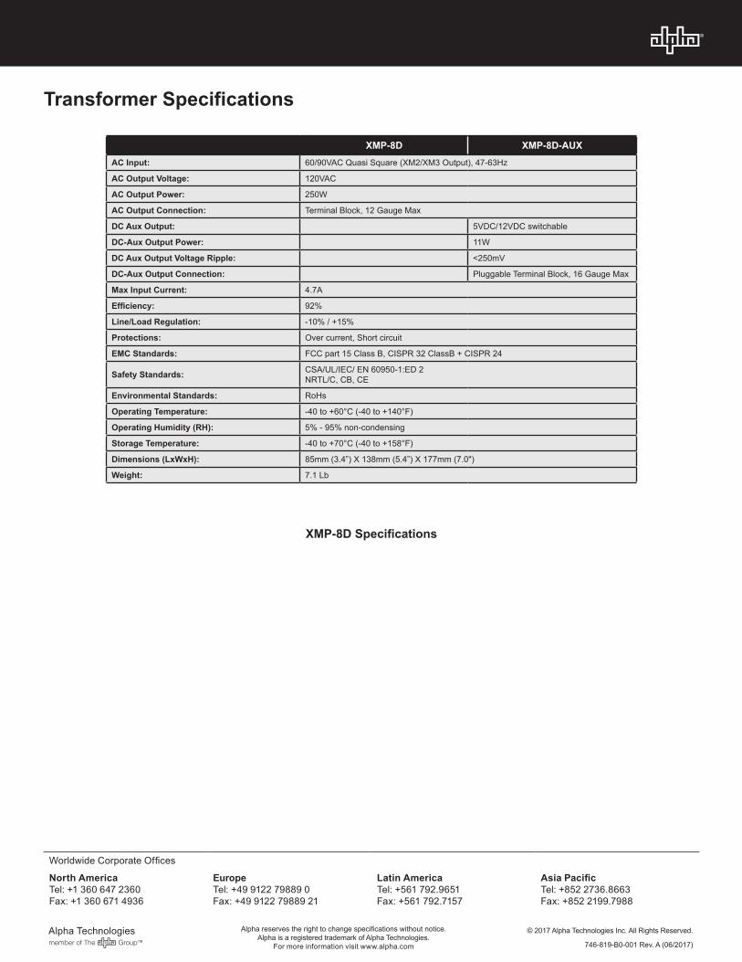
XMP-8D XMP-8D-AUXAC Input: 60/90VAC Quasi Square (XM2/XM3 Output), 47-63Hz
AC Output Voltage: 120VAC
AC Output Power: 250W
AC Output Connection: Terminal Block, 12 Gauge Max
DC Aux Output: 5VDC/12VDC switchable
DC-Aux Output Power: 11W
DC Aux Output Voltage Ripple: <250mV
DC-Aux Output Connection: Pluggable Terminal Block, 16 Gauge Max
Max Input Current: 4.7A
Efficiency: 92%
Line/Load Regulation: -10% / +15%
Protections: Over current, Short circuit
EMC Standards: FCC part 15 Class B, CISPR 32 ClassB + CISPR 24
Safety Standards: CSA/UL/IEC/ EN 60950-1:ED 2NRTL/C, CB, CE
Environmental Standards: RoHs
Operating Temperature: -40 to +60°C (-40 to +140°F)
Operating Humidity (RH): 5% - 95% non-condensing
Storage Temperature: -40 to +70°C (-40 to +158°F)
Dimensions (LxWxH): 85mm (3.4”) X 138mm (5.4”) X 177mm (7.0")
Weight: 7.1 Lb
Transformer Specifications
XMP-8D Specifications