Embed Size (px)
Citation preview

ALPHA 100K TMA®
MANUALFOR MODEL TMA8190
ENERGY ABSORPTION SYSTEMS, INC.A Quixote Company
Corporate Offices:One East Wacker Dr., Chicago, IL 60601-2076Telephone: (312) 467-6750FAX: (312) 467-1356
Engineering and Manufacturing Facilities:Rocklin, CAPell City, AL
E.A.S.I. Part No. 2750122-0000Revision Date 2/25/99F
ALPHA 100K TMA™ALPHA 100K TMA®
2
Table of Contents
General Information ............................. 2
Installation Instructions ......................... 4
Detail Drawings ................................... 8A
Operation Instructions ........................... 9
Attaching and Detaching ........................ 11
General Maintenance ........................... 14
Repair Instructions ............................... 17
Limitations and Warnings ...................... 19
General Information
Important Introductory Notes
This manual contains important information on theALPHA 100K Truck Mounted Attenuator (TMA), Model8190, 90 degree Tilt System. Proper installation andoperation of the ALPHA 100K TMA is essential to assuremaximum performance. Take the time to review thisentire manual thoroughly prior to installing and/or oper-ating the Energy Absorption Systems, Inc. TMA.
If you need additional information, or have any questionsabout the ALPHA 100K TMA, please call Energy AbsorptionSystems' Customer Service Department at 1-888-32-ENERG.
System OverviewThe ALPHA 100K TMA is a lightweight, highly efficientattenuator system designed for installation on the back oftrucks. The system consists of an aluminum cartridgewith a Durashell® Nose, a backup and a backup supportstructure with five auxiliary aluminum cartridges (totalweight is approximately 1180 kg [2600 lbs]).
The assembled components of the ALPHA 100K TMASystem are designed for attachment and detachmentfrom the truck, as one unit. Jacks attached to thecartridge, backup & support frame facilitate this process.Only the underride assembly remains attached to thetruck.
The 350DX (rear) cartridge is equipped with one rearmounted steel wheeled jack, which when retracted, actsas a skid protector. The two rear bottom, outside cornersof the cartridge are protected by plastic skid protectors.
The 350DX cartridge is equipped with a standard trailerlighting system, including brake lights, tail lights, turnsignals, and an ICC bar light. Wiring is normally routedthrough and secured inside the cartridge.
Refer to Figure 10 for a diagram of the ALPHA 100K TMASystem.
The hydraulic tilt system consists of a pump, 12 or 24 voltDC motor, cylinders, hoses, switches, wiring and othersubcomponents which enable the 350DX cartridge to tilt90 degrees from horizontal. Included with this packageis a mechanical locking device to secure the cartridge inthe 90 degree position. For greater ground clearance, theentire system can be tilted 10 degrees from horizontal.The hydraulic tilt system is extremely useful whentransporting or maneuvering the truck in confined areas.
The hydraulic system is shipped factory assembled andmounted to the backup and the support frame assembly.
RETURN GOODS POLICY
Before returning any goods for credit pleasecontact Energy Absorption Systems Inc. Cus-tomer Service Department at 1-888-32-ENERG oryour local distributor for proper instructions.
For Customer Service Call1-888-32-ENERG 3
The ALPHA 100K TMA® System is designed for truckswith a Gross Vehicle Weight (GVW) ranging between 7300kg [16,090 lbs] and 12 000 kg [26,460 lbs]. To achieveoptimum TMA performance, the traveling weight of thevehicle should be between 7300 kg [16,090 lbs] and9000 kg [19,845 lbs].
Energy Absorptions Systems TMAs have consistentlyproven to be effective in.....
• safely stopping the errant motorist
• protecting the shadow vehicle occupants
• minimizing damage to the shadow vehicle
A minimum 7300 kg [16,090 lbs] truck equipped with theALPHA 100K TMA system has a forward skid distance (rollahead) of less than 6 m [20 ft] during impact by either a820 kg [1808 lbs] or 2000 kg [4410 lbs] vehicle travelingat a design speed of 100 km/h [62 mph]. This forwardskid distance is dependent on the truck wheels beinglocked, the transmission in second gear, and the parkingbrake set with the truck situated on clean dry pavement.
Note: The use of a lighter weight shadowvehicle can result in a greater, less predictableroll ahead distance.
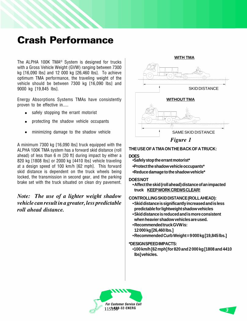
SAME SKID DISTANCE
WITHOUT TMA
WITH TMA
SKID DISTANCE
THE USE OF A TMA ON THE BACK OF A TRUCK:
DOES•Safely stop the errant motorist*•Protect the shadow vehicle occupants*•Reduce damage to the shadow vehicle*
DOES NOT•Affect the skid (roll ahead) distance of an impactedtruck KEEP WORK CREWS CLEAR!
CONTROLLING SKID DISTANCE (ROLL AHEAD):•Skid distance is significantly increased and is lesspredictable for lightweight shadow vehicles
•Skid distance is reduced and is more consistentwhen heavier shadow vehicles are used.
•Recommended truck GVW is:12 000 kg [26,460 lbs.]
•Recommended Curb Weight = 9 000 kg [19,845 lbs.]
*DESIGN SPEED IMPACTS:•100 km/h [62 mph] for 820 and 2 000 kg [1808 and 4410lbs] vehicles.
Figure 1
Crash Performance
ALPHA 100K TMA™ALPHA 100K TMA®
4
Required Tools
1. Welding equipment (for 1/2" plate)
2. Cutting torch
3. Hammer
4. Drift pin or alignment pin
5. Tape measure
6. 1/2" drive socket wrench
7. 1/2" drive sockets (1/2", 9/16", 5/8", 3/4", 15/16", 1", 1-1/8", 1-1/2")
8. Open end wrenches (1/2",9/16", 5/8", 3/4", 15/16",1", 1-1/8", 1-1/2")
9. 12" crescent wrenches (2)
10. Carpenter’s 24" bubble level
11. Marking implement (pencil, soap stone)
12. (2) Floor jacks (a forklift is recommended)
13. Drill motor for 13/16" diameter bit
14. 13/16" diameter bit and pilot drill for same
15. Center punch
16. Torque wrench
17. Hydraulic fluid (use Dexron® II or III fluid only)*
*Shipped with system
Installation Instructions
Read and understand all instructions before beginning installation.Preparation1) Truck ballastPark on a level surface (use bubble level). The truckshould be as close to the final driving weight as possible.The entire TMA and underride weighs close to 1200 Kg[2,650 lbs]. Add an equivalent weight to the rear of thetruck to load the springs down to the proper height beforeattaching the underride. If ballast must be added toachieve the 7300 kg [16,090 lbs] minimum weight, addit at this time. It must be properly anchored to the truckto keep it in place during an impact. Ideally an adequatelysized truck that requires no ballast should be used.
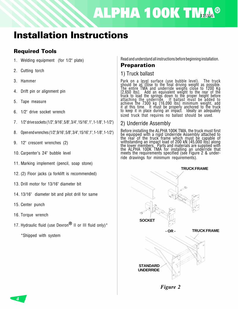
2) Underride AssemblyBefore installing the ALPHA 100K TMA, the truck must firstbe equipped with a rigid Underride Assembly attached tothe rear of the truck frame which must be capable ofwithstanding an impact load of 200 kN [45,000 lbs] alongthe lower members. Parts and materials are supplied withthe ALPHA 100K TMA for installing an underride thatmeets the requirements specified (see Figure 2 & under-ride drawings for minimum requirements).
Figure 2
SOCKET
TRUCK FRAME
STANDARDUNDERRIDE
TRUCK FRAME- OR -
For Customer Service Call1-888-32-ENERG 5
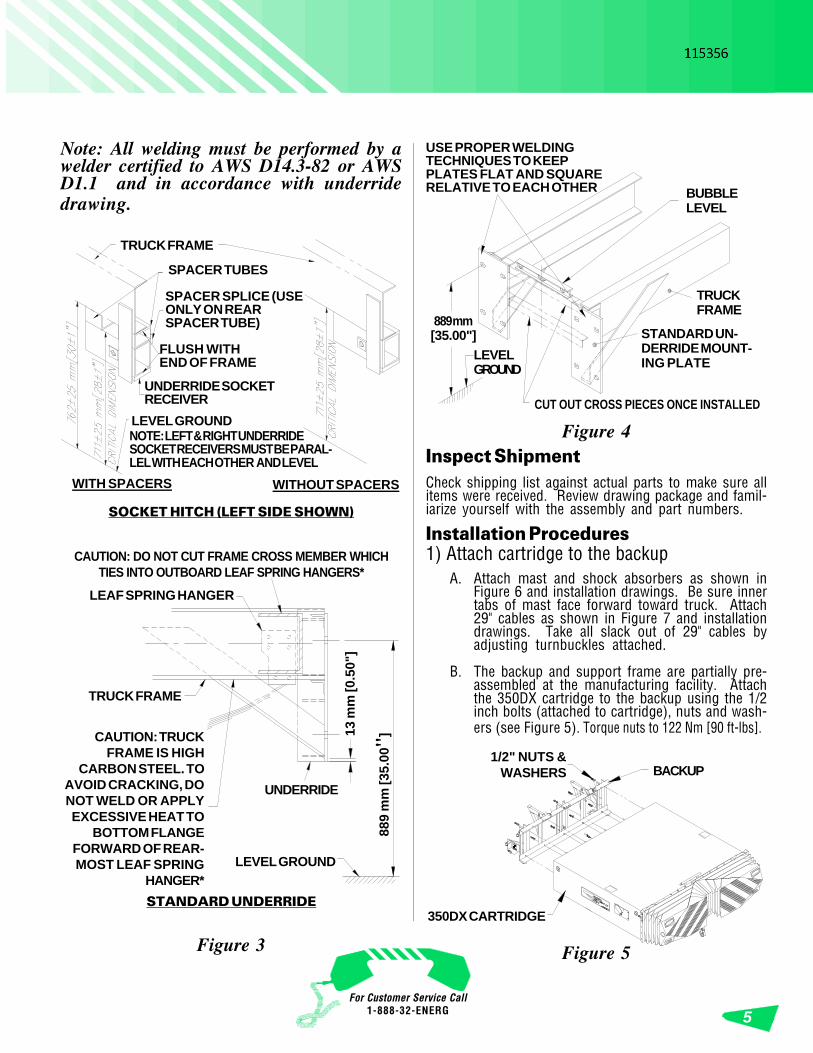
Figure 4
CAUTION: DO NOT CUT FRAME CROSS MEMBER WHICHTIES INTO OUTBOARD LEAF SPRING HANGERS*
CAUTION: TRUCKFRAME IS HIGH
CARBON STEEL. TOAVOID CRACKING, DONOT WELD OR APPLYEXCESSIVE HEAT TO
BOTTOM FLANGEFORWARD OF REAR-MOST LEAF SPRING
HANGER*
TRUCK FRAME
LEAF SPRING HANGER
LEVEL GROUND
889
mm
[35.
00"]
USE PROPER WELDINGTECHNIQUES TO KEEPPLATES FLAT AND SQUARERELATIVE TO EACH OTHER
TRUCKFRAME
STANDARD UN-DERRIDE MOUNT-ING PLATE
CUT OUT CROSS PIECES ONCE INSTALLED
BUBBLELEVEL
LEVELGROUND
Figure 3
UNDERRIDE
13 m
m [0
.50"
]
889 mm[35.00"]
STANDARD UNDERRIDE
SOCKET HITCH (LEFT SIDE SHOWN)
SPACER TUBES
SPACER SPLICE (USEONLY ON REARSPACER TUBE)
TRUCK FRAME
FLUSH WITHEND OF FRAME
WITH SPACERS WITHOUT SPACERS
UNDERRIDE SOCKETRECEIVER
LEVEL GROUNDNOTE: LEFT & RIGHT UNDERRIDESOCKET RECEIVERS MUST BE PARAL-LEL WITH EACH OTHER AND LEVEL Inspect Shipment
Check shipping list against actual parts to make sure allitems were received. Review drawing package and famil-iarize yourself with the assembly and part numbers.
Installation Procedures1) Attach cartridge to the backup
A. Attach mast and shock absorbers as shown inFigure 6 and installation drawings. Be sure innertabs of mast face forward toward truck. Attach29" cables as shown in Figure 7 and installationdrawings. Take all slack out of 29" cables byadjusting turnbuckles attached.
B. The backup and support frame are partially pre-assembled at the manufacturing facility. Attachthe 350DX cartridge to the backup using the 1/2inch bolts (attached to cartridge), nuts and wash-ers (see Figure 5). Torque nuts to 122 Nm [90 ft-lbs].
Figure 5
1/2" NUTS &WASHERS BACKUP
350DX CARTRIDGE
Note: All welding must be performed by awelder certified to AWS D14.3-82 or AWSD1.1 and in accordance with underridedrawing.
ALPHA 100K TMA™ALPHA 100K TMA®
6
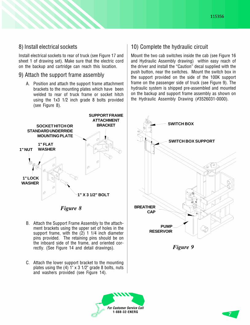
2) Lift systemLift support frame, backup and cartridge enough to extend cartridgejack, reposition backup jacks and rotate support frame jacks tovertical position (see Figure 15). Extend jacks to “raise” the 350DXcartridge height to 305 mm +/- 6 mm [12" +/-1/4"] at front, 330 mm+/- 6 mm [13" +/-1/4"] at rear (see Figure 7).
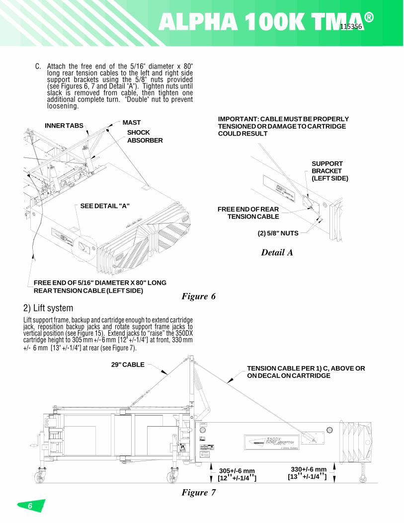
C. Attach the free end of the 5/16" diameter x 80"long rear tension cables to the left and right sidesupport brackets using the 5/8" nuts provided(see Figures 6, 7 and Detail "A"). Tighten nuts untilslack is removed from cable, then tighten oneadditional complete turn. "Double" nut to preventloosening.
Detail A
(2) 5/8" NUTS
FREE END OF REARTENSION CABLE
SUPPORTBRACKET(LEFT SIDE)
Figure 6
FREE END OF 5/16" DIAMETER X 80" LONGREAR TENSION CABLE (LEFT SIDE)
SEE DETAIL "A"
INNER TABS MASTSHOCKABSORBER
Figure 7
305+/-6 mm[12"+/-1/4"]
330+/-6 mm[13"+/-1/4"]
TENSION CABLE PER 1) C, ABOVE ORON DECAL ON CARTRIDGE
29" CABLE
IMPORTANT: CABLE MUST BE PROPERLYTENSIONED OR DAMAGE TO CARTRIDGECOULD RESULT
For Customer Service Call1-888-32-ENERG 7
8) Install electrical socketsInstall electrical sockets to rear of truck (see Figure 17 andsheet 1 of drawing set). Make sure that the electric cordon the backup and cartridge can reach this location.
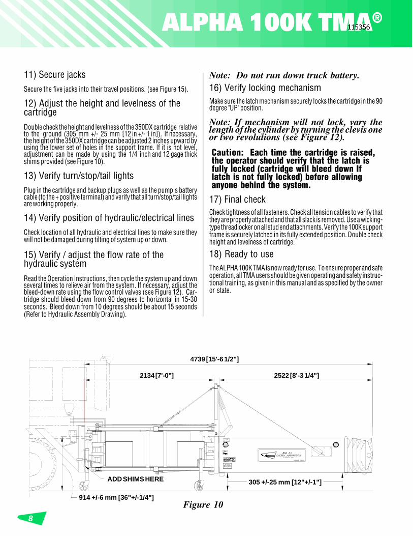
9) Attach the support frame assemblyA. Position and attach the support frame attachment
brackets to the mounting plates which have beenwelded to rear of truck frame or socket hitchusing the 1x3 1/2 inch grade 8 bolts provided(see Figure 8).
B. Attach the Support Frame Assembly to the attach-ment brackets using the upper set of holes in thesupport frame, with the (2) 1 1/4 inch diameterpins provided. The retaining pins should be onthe inboard side of the frame, and oriented cor-rectly. (See Figure 14 and detail drawings).
C. Attach the lower support bracket to the mountingplates using the (4) 1" x 3 1/2" grade 8 bolts, nutsand washers provided (see Figure 14).
10) Complete the hydraulic circuitMount the two cab switches inside the cab (see Figure 16and Hydraulic Assembly drawing) within easy reach ofthe driver and install the “Caution” decal supplied with thepush button, near the switches. Mount the switch box inthe support provided on the side of the 100K supportframe on the passenger side of truck (see Figure 9). Thehydraulic system is shipped pre-assembled and mountedon the backup and support frame assembly as shown onthe Hydraulic Assembly Drawing (#3526031-0000).
SUPPORT FRAMEATTACHMENT
BRACKET
1" X 3 1/2" BOLT
SOCKET HITCH ORSTANDARD UNDERRIDE
MOUNTING PLATE
Figure 8
1" FLATWASHER1" NUT
1" LOCKWASHER
Figure 9
SWITCH BOX SUPPORT
SWITCH BOX
PUMPRESERVOIR
BREATHERCAP
ALPHA 100K TMA™ALPHA 100K TMA®
8
11) Secure jacksSecure the five jacks into their travel positions. (see Figure 15).
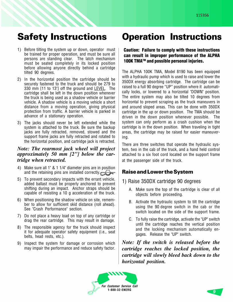
12) Adjust the height and levelness of thecartridgeDouble check the height and levelness of the 350DX cartridge relativeto the ground (305 mm +/- 25 mm [12 in +/- 1 in]). If necessary,the height of the 350DX cartridge can be adjusted 2 inches upward byusing the lower set of holes in the support frame. If it is not level,adjustment can be made by using the 1/4 inch and 12 gage thickshims provided (see Figure 10).
13) Verify turn/stop/tail lightsPlug in the cartridge and backup plugs as well as the pump's batterycable (to the + positive terminal) and verify that all turn/stop/tail lightsare working properly.
14) Verify position of hydraulic/electrical linesCheck location of all hydraulic and electrical lines to make sure theywill not be damaged during tilting of system up or down.
15) Verify / adjust the flow rate of thehydraulic systemRead the Operation Instructions, then cycle the system up and downseveral times to relieve air from the system. If necessary, adjust thebleed-down rate using the flow control valves (see Figure 12). Car-tridge should bleed down from 90 degrees to horizontal in 15-30seconds. Bleed down from 10 degrees should be about 15 seconds(Refer to Hydraulic Assembly Drawing).
Note: Do not run down truck battery.16) Verify locking mechanismMake sure the latch mechanism securely locks the cartridge in the 90degree "UP" position.
Note: If mechanism will not lock, vary thelength of the cylinder by turning the clevis oneor two revolutions (see Figure 12).
Caution: Each time the cartridge is raised,the operator should verify that the latch isfully locked (cartridge will bleed down Iflatch is not fully locked) before allowinganyone behind the system.
17) Final checkCheck tightness of all fasteners. Check all tension cables to verify thatthey are properly attached and that all slack is removed. Use a wicking-type threadlocker on all stud end attachments. Verify the 100K supportframe is securely latched in its fully extended position. Double checkheight and levelness of cartridge.
18) Ready to useThe ALPHA 100K TMA is now ready for use. To ensure proper and safeoperation, all TMA users should be given operating and safety instruc-tional training, as given in this manual and as specified by the owneror state.
2134 [7'-0"]
914 +/-6 mm [36"+/-1/4"]Figure 10
305 +/-25 mm [12"+/-1"]
2522 [8'-3 1/4"]
4739 [15'-6 1/2"]
ADD SHIMS HERE
For Customer Service Call1-888-32-ENERG 9
The ALPHA 100K TMA, Model 8190 has been equippedwith a hydraulic pump which is used to raise and lower the350DX energy absorbing cartridge. The cartridge can beraised to a full 90 degree “UP” position where it automati-cally locks, or lowered to a horizontal "DOWN" position.The entire system may also be tilted 10 degrees fromhorizontal to prevent scraping as the truck maneuvers inand around sloped areas. This can be done with 350DXcartridge in the up or down position. The TMA should bedriven in the down position whenever possible. Thesystem can only perform as a crash cushion when thecartridge is in the down position. When traveling in tightareas, the cartridge may be raised for easier maneuver-ing.
There are three switches that operate the hydraulic sys-tem, two in the cab of the truck, and a hand held controlattached to a six foot cord located on the support frameat the passenger side of the truck.
Raise and Lower the System
1) Raise 350DX cartridge 90 degrees.
A. Make sure the top of the cartridge is clear of allobjects before proceeding.
B. Activate the hydraulic system to tilt the cartridgeusing the 90 degree switch in the cab or theswitch located on the side of the support frame.
C. To fully raise the cartridge, activate the "UP" switchuntil the cartridge reaches the vertical positionand the locking mechanism automatically en-gages. Release the "UP" switch.
Note: If the switch is released before thecartridge reaches the locked position, thecartridge will slowly bleed back down to thehorizontal position.
Operation Instructions1) Before tilting the system up or down, operator must
be trained for proper operation, and must be sure allpersons are standing clear. The latch mechanismmust be seated completely in its locked positionbefore allowing anyone directly behind a cartridgetilted 90 degrees.
2) In the horizontal position the cartridge should besecurely fastened to the truck and should be 279 to330 mm [11 to 13"] off the ground and LEVEL. Thecartridge shall be left in the down position wheneverthe truck is being used as a shadow vehicle or barriervehicle. A shadow vehicle is a moving vehicle a shortdistance from a moving operation, giving physicalprotection from traffic. A barrier vehicle is parked inadvance of a stationary operation.
3) The jacks should never be left extended while thesystem is attached to the truck. Be sure the backupjacks are fully retracted, removed, stowed and thesupport frame jacks are fully retracted and rotated tothe horizontal position, and cartridge jack is retracted.
Note: The rearmost jack wheel will projectapproximately 50 mm [2"] below the car-tridge when retracted.4) Make sure all 1" & 1 1/4" diameter pins are in position
and the retaining pins are installed correctly.
5) To prevent secondary impacts with the errant vehicle,added ballast must be properly anchored to preventshifting during an impact. Anchor straps should becapable of resisting a 10 g acceleration of the truck.
6) When positioning the shadow vehicle on site, remem-ber to allow for sufficient skid distance (roll ahead).See "Crash Performance" section.
7) Do not place a heavy load on top of any cartridge ordrag the rear cartridge. This may result in damage.
8) The responsible agency for the truck should inspectit for adequate operator safety equipment (i.e., seatbelts, head rests, etc.).
9) Inspect the system for damage or corrosion whichmay impair the performance and reduce safety factor.
Caution: Failure to comply with these instructionscan result in improper performance of the ALPHA100K TMATM and possible personal injuries.
Safety Instructions
ALPHA 100K TMA®
10
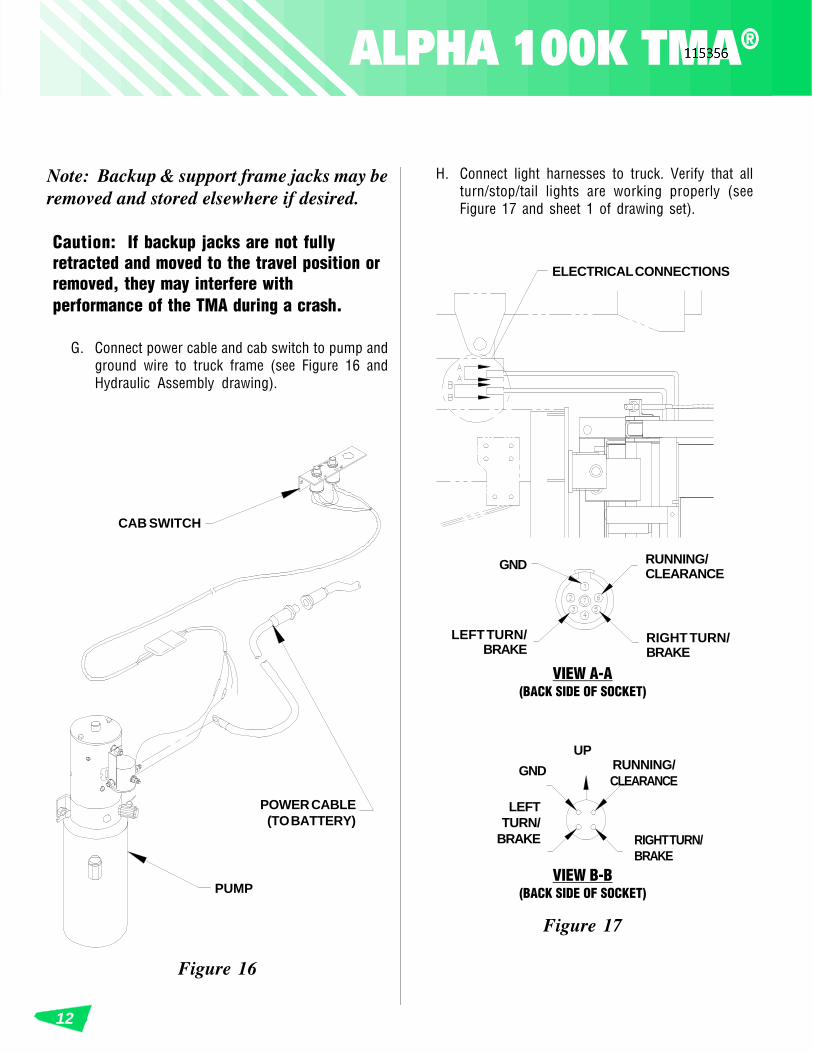
B. Release the switch to lower the cartridge. Thecartridge will then bleed down in approximately15-30 seconds, regulated by the flow controlvalve attached to the cylinder (See Figure 12).
D. Visually inspect the cartridge to ensure it is se-curely locked before transporting or allowinganyone behind it.
E. The external switch and cord should be properlystored before moving the truck.
Caution: Under no circumstances should any-one be allowed behind a tilted cartridge whenthe latch mechanism is not fully seated in itslocked position.
2)Lower 350DX cartridge from 90 degreesThe "DOWN" operation from the 90 degree locked positioncan only be activated with the control at the rear of thetruck. This control has been positioned to allow theoperator to first visually check behind or under the ALPHA100K TMA cartridge, before lowering to the horizontalposition.
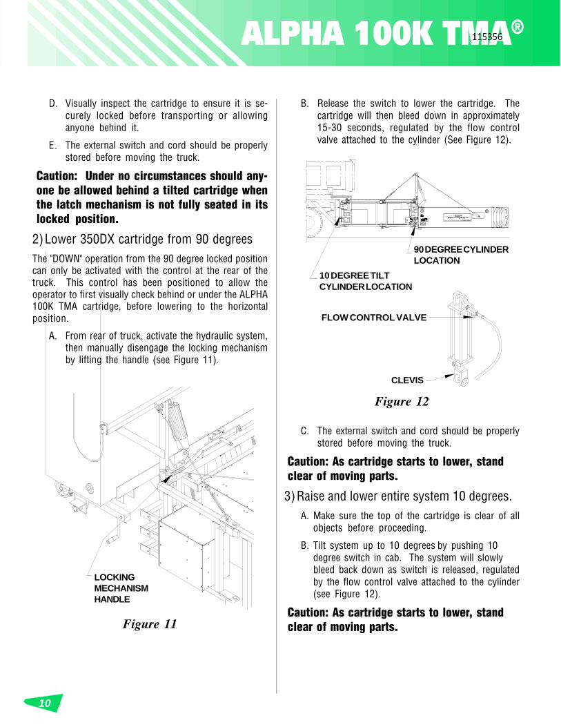
A. From rear of truck, activate the hydraulic system,then manually disengage the locking mechanismby lifting the handle (see Figure 11).
Figure 12
FLOW CONTROL VALVE
90 DEGREE CYLINDERLOCATION
Figure 11
LOCKINGMECHANISMHANDLE
CLEVIS
10 DEGREE TILTCYLINDER LOCATION
C. The external switch and cord should be properlystored before moving the truck.
Caution: As cartridge starts to lower, standclear of moving parts.
3)Raise and lower entire system 10 degrees.A. Make sure the top of the cartridge is clear of all
objects before proceeding.
B. Tilt system up to 10 degrees by pushing 10degree switch in cab. The system will slowlybleed back down as switch is released, regulatedby the flow control valve attached to the cylinder(see Figure 12).
Caution: As cartridge starts to lower, standclear of moving parts.

For Customer Service Call1-888-32-ENERG 11
1" NUT &WASHERS
Figure 14
1 1/4"DIAMETERPINS
SHIMS
LOWER SUPPORTBRACKET
1" DIA. X 3 1/2" LONGGRADE 8 BOLTS
RETAINER PINS
Figure 13
SOCKET
1" DIAMETERPINS
SUPPORT MOUNT
RETAINER PINS
Figure 15
BACKUP JACKS(CLOSE TO
CARTRIDGE)
REAR JACKSUPPORT FRAMEJACKS (CLOSE TO
TRUCK)
Attaching and Detaching1) Attaching
Method I - socket hitch.
A. Park truck on level surface.
B. Move the system to the truck.
C. Slide support mounts into sockets (see Figure13). If the parts bind too much to accomplishthis, disassemble socket hitch and install perstandard underride.
D. Insert pins & retainer pins. (Skip to "D", nextcolumn).
Method II - standard underride.
A. Move the system to the truck.
B. Attach the two upper 1 1/4" diameter pins andretainer pins (see Figure 14).
C. Attach the lower support bracket to the underrideusing (4) 1" diameter x 3 1/2" long, grade 8 bolts,nuts & washers. Lower support bracket is attachedto support frame. Figure 14 shows lower supportbracket detached for clarity (see Figure 14).
Note: Double check to ensure retainer pinsare installed correctly and cannot fall out.
E. Fully retract the support frame jacks and rotatethem to horizontal position (see Figure 15).
F. Remove pin and raise rear jack. Secure into thefull “UP” position (see Figures 15 & 18).
D. Retract the two backup jacks completely and movethem to travel position (see Figure 15).
ALPHA 100K TMA®
12
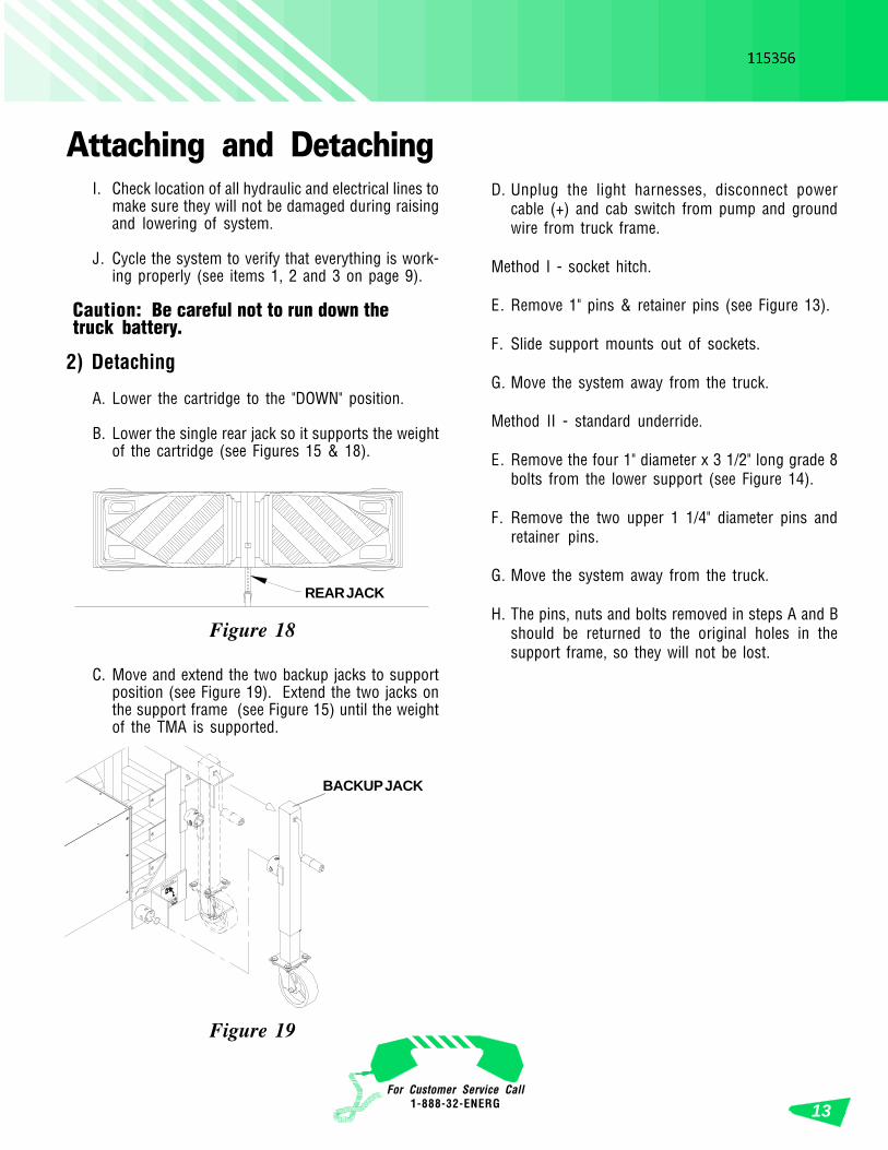
Figure 16
POWER CABLE(TO BATTERY)
CAB SWITCH
PUMP
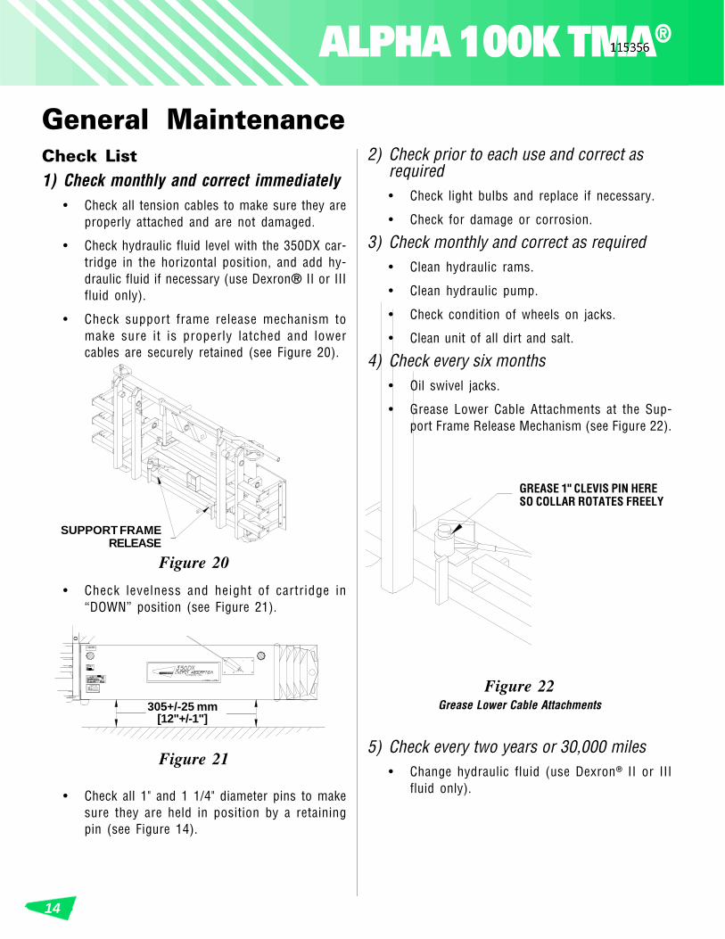
RUNNING/CLEARANCE
GND
RIGHT TURN/BRAKE
LEFTTURN/
BRAKE
VIEW B-B(BACK SIDE OF SOCKET)
UP
RUNNING/CLEARANCE
GND
RIGHT TURN/BRAKE
LEFT TURN/BRAKE
VIEW A-A(BACK SIDE OF SOCKET)
Figure 17
ELECTRICAL CONNECTIONS
H. Connect light harnesses to truck. Verify that allturn/stop/tail lights are working properly (seeFigure 17 and sheet 1 of drawing set).
Note: Backup & support frame jacks may beremoved and stored elsewhere if desired.
Caution: If backup jacks are not fullyretracted and moved to the travel position orremoved, they may interfere withperformance of the TMA during a crash.
G. Connect power cable and cab switch to pump andground wire to truck frame (see Figure 16 andHydraulic Assembly drawing).
For Customer Service Call1-888-32-ENERG 13
Figure 18
REAR JACK
Attaching and DetachingD. Unplug the light harnesses, disconnect power
cable (+) and cab switch from pump and groundwire from truck frame.
Method I - socket hitch.
E. Remove 1" pins & retainer pins (see Figure 13).
F. Slide support mounts out of sockets.
G. Move the system away from the truck.
Method II - standard underride.
E. Remove the four 1" diameter x 3 1/2" long grade 8bolts from the lower support (see Figure 14).
F. Remove the two upper 1 1/4" diameter pins andretainer pins.
G. Move the system away from the truck.
H. The pins, nuts and bolts removed in steps A and Bshould be returned to the original holes in thesupport frame, so they will not be lost.
Figure 19
BACKUP JACK
I. Check location of all hydraulic and electrical lines tomake sure they will not be damaged during raisingand lowering of system.
J. Cycle the system to verify that everything is work-ing properly (see items 1, 2 and 3 on page 9).
Caution: Be careful not to run down thetruck battery.
2) Detaching
A. Lower the cartridge to the "DOWN" position.
B. Lower the single rear jack so it supports the weightof the cartridge (see Figures 15 & 18).
C. Move and extend the two backup jacks to supportposition (see Figure 19). Extend the two jacks onthe support frame (see Figure 15) until the weightof the TMA is supported.
ALPHA 100K TMA®
14
2) Check prior to each use and correct asrequired• Check light bulbs and replace if necessary.
• Check for damage or corrosion.
3) Check monthly and correct as required• Clean hydraulic rams.
• Clean hydraulic pump.
• Check condition of wheels on jacks.
• Clean unit of all dirt and salt.
4) Check every six months• Oil swivel jacks.
• Grease Lower Cable Attachments at the Sup-port Frame Release Mechanism (see Figure 22).
Figure 22
GREASE 1" CLEVIS PIN HERESO COLLAR ROTATES FREELY
General MaintenanceCheck List1) Check monthly and correct immediately
• Check all tension cables to make sure they areproperly attached and are not damaged.
• Check hydraulic fluid level with the 350DX car-tridge in the horizontal position, and add hy-draulic fluid if necessary (use Dexron® II or IIIfluid only).
• Check support frame release mechanism tomake sure it is properly latched and lowercables are securely retained (see Figure 20).
Figure 21
305+/-25 mm[12"+/-1"]
Figure 20
SUPPORT FRAMERELEASE
• Check all 1" and 1 1/4" diameter pins to makesure they are held in position by a retainingpin (see Figure 14).
• Check levelness and height of cartridge in“DOWN” position (see Figure 21).
5) Check every two years or 30,000 miles• Change hydraulic fluid (use Dexron® II or III
fluid only).
Grease Lower Cable Attachments
15For Customer Service
Call1-888-32-ENERG
Figure 23
REMOVE THESECLEVIS PINS TO OPEN
UP SUPPORT FRAME
FRONT
REAR
Figure 24
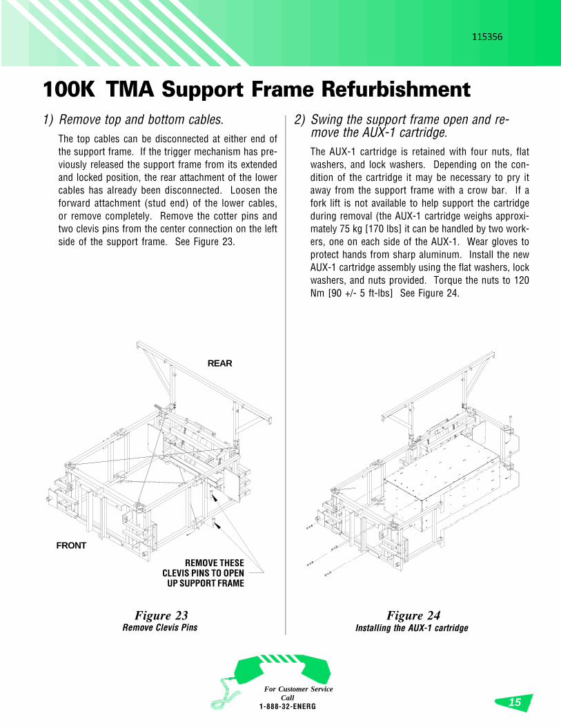
100K TMA Support Frame Refurbishment1) Remove top and bottom cables.
The top cables can be disconnected at either end ofthe support frame. If the trigger mechanism has pre-viously released the support frame from its extendedand locked position, the rear attachment of the lowercables has already been disconnected. Loosen theforward attachment (stud end) of the lower cables,or remove completely. Remove the cotter pins andtwo clevis pins from the center connection on the leftside of the support frame. See Figure 23.
2) Swing the support frame open and re-move the AUX-1 cartridge.The AUX-1 cartridge is retained with four nuts, flatwashers, and lock washers. Depending on the con-dition of the cartridge it may be necessary to pry itaway from the support frame with a crow bar. If afork lift is not available to help support the cartridgeduring removal (the AUX-1 cartridge weighs approxi-mately 75 kg [170 lbs] it can be handled by two work-ers, one on each side of the AUX-1. Wear gloves toprotect hands from sharp aluminum. Install the newAUX-1 cartridge assembly using the flat washers, lockwashers, and nuts provided. Torque the nuts to 120Nm [90 +/- 5 ft-lbs] See Figure 24.
Remove Clevis Pins Installing the AUX-1 cartridge
ALPHA 100K TMA®
16
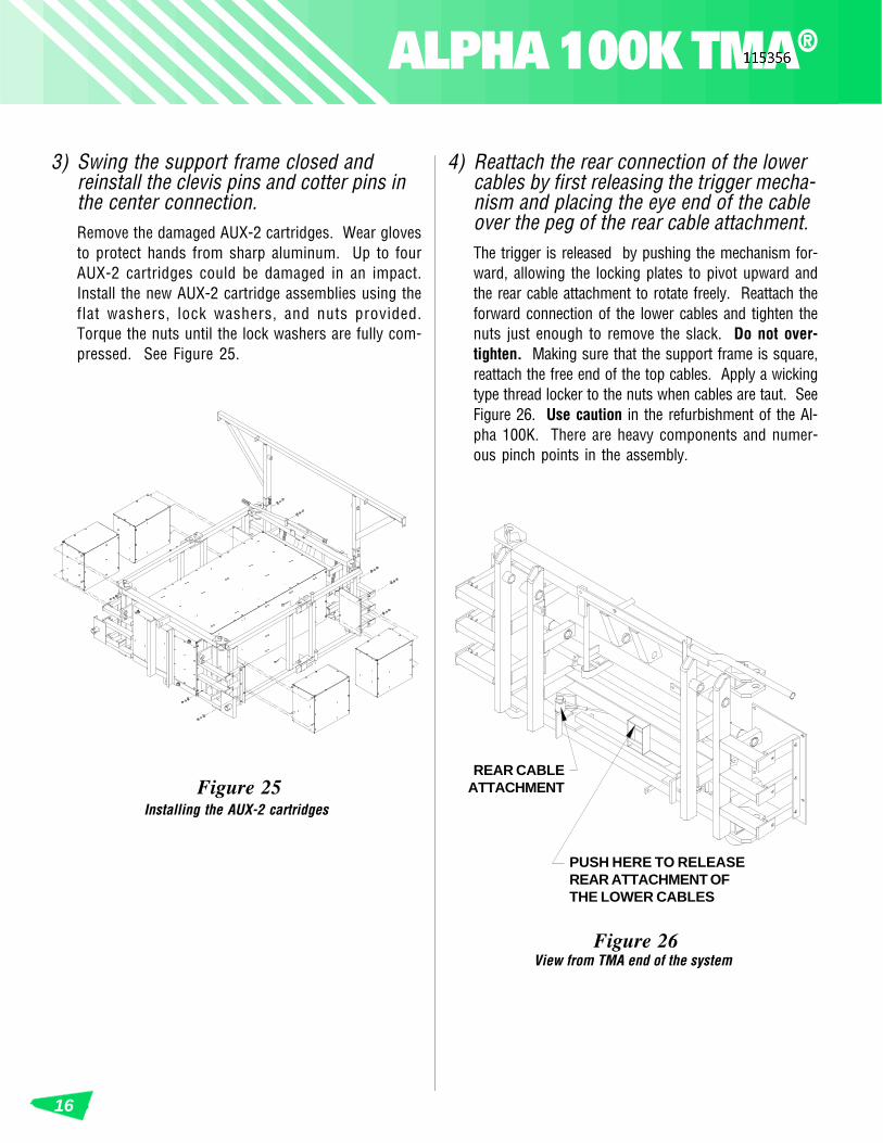
4) Reattach the rear connection of the lowercables by first releasing the trigger mecha-nism and placing the eye end of the cableover the peg of the rear cable attachment.The trigger is released by pushing the mechanism for-ward, allowing the locking plates to pivot upward andthe rear cable attachment to rotate freely. Reattach theforward connection of the lower cables and tighten thenuts just enough to remove the slack. Do not over-tighten. Making sure that the support frame is square,reattach the free end of the top cables. Apply a wickingtype thread locker to the nuts when cables are taut. SeeFigure 26. Use caution in the refurbishment of the Al-pha 100K. There are heavy components and numer-ous pinch points in the assembly.
Figure 26
REAR CABLEATTACHMENT
PUSH HERE TO RELEASEREAR ATTACHMENT OFTHE LOWER CABLES
Figure 25
3) Swing the support frame closed andreinstall the clevis pins and cotter pins inthe center connection.Remove the damaged AUX-2 cartridges. Wear glovesto protect hands from sharp aluminum. Up to fourAUX-2 cartridges could be damaged in an impact.Install the new AUX-2 cartridge assemblies using theflat washers, lock washers, and nuts provided.Torque the nuts until the lock washers are fully com-pressed. See Figure 25.
Installing the AUX-2 cartridges
View from TMA end of the system
17For Customer Service
Call1-888-32-ENERG
Repair Instructions1) Cartridge cannot be tilted up
• Consult hydraulic schematic in this manual.
• Clogged filters or improperly adjusted “inter-nal pump relief valve” could be the problem.
• There may not be enough hydraulic fluid in thepump reservoir. Use only Dexron® II or III fluid.
2) Cartridge will not go down• Refer to step 1 above. The flow control valve
for adjusting the bleed down rate may be tootight or clogged with dirt.
• Check and make sure the support braces areclearing the seats on the support frame, whenhandle is raised.
3) Latch does not work properly• Check for areas where it might be binding and
correct the problem.
• Refer to Step 1 above.
4) Lights will not work• Replace affected light bulb(s).
• Check wire for damage.
• Using a volt/ohm meter, trouble shoot and lo-cate the problem.
5) 350DX cartridge is not level• Temporary extra load in truck.
• Support frame improperly installed.
• Weakening truck springs.
• Shims can be added or removed to adjust the lev-elness of the 350DX cartridge. Each 1/4" thick shimwill raise or lower the rear end of the cartridge ap-proximately 51 mm [2"]. 12 gage thick shims arealso supplied. Height is adjusted up or down byusing the attachment holes in the support frame.The correct final position of the cartridge shouldbe 305 mm +/-25 mm [12" +/-1"] above a levelsurface.
6) Support frame is not fully extended or isnot latched (see Figure 20)• Fully extend support frame and reattach lower
cables.
• Secure support frame release mechanism inproperly latched position.
Note: The following is a general description of vari-ous types of damage that can occur to the DurashellNose, the 350DX, AUX-1, or AUX-2 Cartridges.Please review and heed the following recommenda-tions to ensure proper impact performance. Pleaserefer to Figure 27 and 28 on the following page.
7) Durashell® Nose damageThe Durashell Nose is a resilient plastic nose that nor-mally recovers its shape after nuisance hits. How-ever, if either the left or right side is damaged, it mustbe replaced in the following manner:
a. Remove the bolts and washers attaching thenose to the cartridge.
b. Disconnect the light plugs from the lights.
c. Connect the light plugs to the lights in thenew nose.
d. Attach the new nose to cartridge using thebolts and washers previously removed.
e. Lights and grommets, if undamaged, may besalvaged.
ALPHA 100K TMA®
18
350DX CARTRIDGE
“MAJORDAMAGE” - DONOT ATTEMPTTO REPAIR
305 mm [1'-0"]
1219 mm[4'-0"]
REAR 2134 mm[7'-0"]
Damage to 350DX Cartridge
EXAMPLES OF "MINORDAMAGE" (CAN BEREPAIRED)
REAR OFCARTRIDGE (withDURASHELLNOSE removed)914 mm [3'-0"]
Figure 28
AUX-1 CARTRIDGE
“MAJORDAMAGE” -DO NOTATTEMPTTO REPAIR
EXAMPLESOF "MINOR
DAMAGE"(CAN BE
REPAIRED)
AUX-2 CARTRIDGE
Note: Energy Absorption Systems personnel are avail-able to help evaluate the condition of damaged TMACartridges. Several photos of the damaged area, takenat different angles, should be submitted for evalua-tion. (Send to: Customer Service Manager, One EastWacker Drive, Chicago, Illinois 60601)
Damage to AUX-1 & AUX-2 Cartridges
Figure 27
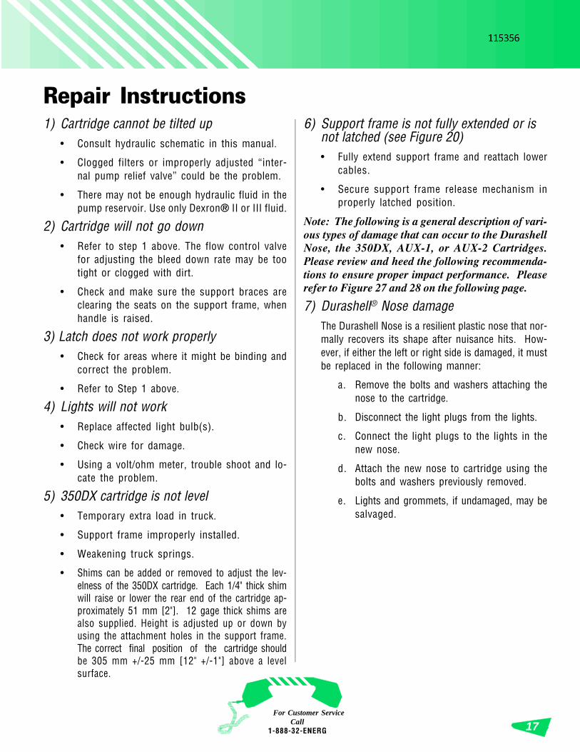
350DX cartridge is considered "major" damage. Dam-age to the front 1219 mm [4'] of the side covers, orsevere buckling along any covers is also considered"major" damage. Such damage could significantlyaffect the total energy absorbing capacity of the sys-tem. Repairs for "major" damage are not recom-mended. (See General Information if an evaluation isdesired.)
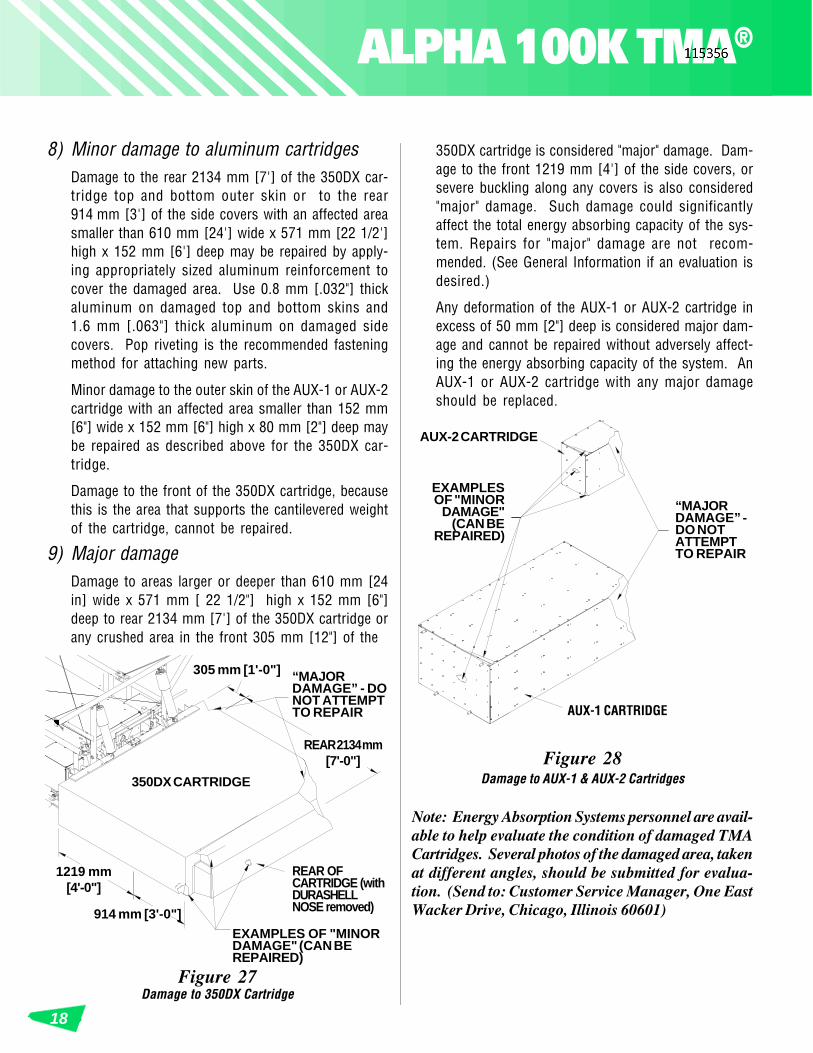
Any deformation of the AUX-1 or AUX-2 cartridge inexcess of 50 mm [2"] deep is considered major dam-age and cannot be repaired without adversely affect-ing the energy absorbing capacity of the system. AnAUX-1 or AUX-2 cartridge with any major damageshould be replaced.
8) Minor damage to aluminum cartridgesDamage to the rear 2134 mm [7'] of the 350DX car-tridge top and bottom outer skin or to the rear914 mm [3'] of the side covers with an affected areasmaller than 610 mm [24'] wide x 571 mm [22 1/2']high x 152 mm [6'] deep may be repaired by apply-ing appropriately sized aluminum reinforcement tocover the damaged area. Use 0.8 mm [.032"] thickaluminum on damaged top and bottom skins and1.6 mm [.063"] thick aluminum on damaged sidecovers. Pop riveting is the recommended fasteningmethod for attaching new parts.
Minor damage to the outer skin of the AUX-1 or AUX-2cartridge with an affected area smaller than 152 mm[6"] wide x 152 mm [6"] high x 80 mm [2"] deep maybe repaired as described above for the 350DX car-tridge.
Damage to the front of the 350DX cartridge, becausethis is the area that supports the cantilevered weightof the cartridge, cannot be repaired.
9) Major damageDamage to areas larger or deeper than 610 mm [24in] wide x 571 mm [ 22 1/2"] high x 152 mm [6"]deep to rear 2134 mm [7'] of the 350DX cartridge orany crushed area in the front 305 mm [12"] of the
19For Customer Service
Call1-888-32-ENERG
The ALPHA 100K TMA® (Truck MountedAttenuator) has been tested and evaluated per therecommendations of the National Cooperative HighwayResearch Program Report 350 (NCHRP 350) for TestLevel 3. The ALPHA 100K TMA as currently designed,is capable of decelerating and stopping light andheavy vehicles (820 and 2 000 kg [1808 and 4410lbs]) when the rear of the 350DX cartridge is impactedhead-on at 100 km/h [62 mph].
To achieve acceptable impact performance, theALPHA 100K TMA must be mounted to a truckwith a 7 300 to 12 000 kg [16,090 to 26,460 lbs.]gross vehicle weight rating (actual weight should notexceed 9 000 kg [19,845 lbs]). The 350DX cartridgemust be level and the bottom of the cartridge must be305 mm +/- 25 mm [12" +/- 1"] above the ground.
Impacts that exceed the design capabilities de-scribed in this manual (vehicle weight, speed and impactangle) may not result in acceptable crash performance asdescribed in NCHRP 350 relative to structural ad-equacy, occupant risk, and vehicle trajectory factors.
* Copy may be obtained from:Transportation Research BoardNational Research Council2101 Constitution Avenue, N.W.Washington, D.C. 20418
Limitations And Warnings


![TMA Standard Operating Procedure [Updated April 30, 2015]TMA+_updated+April+30+2015_.pdf · TMA Standard Operating Procedure [Updated April 30, 2015] Calibrating the TMA To obtain](https://img.pdfslide.us/doc/110x75/5e53ad55883f92255623d6b9/tma-standard-operating-procedure-updated-april-30-2015-tmaupdatedapril302015pdf.jpg)