Embed Size (px)
Citation preview
7/27/2019 ALLISS Antenna Transmission System for Shortwave Broacast
http://slidepdf.com/reader/full/alliss-antenna-transmission-system-for-shortwave-broacast 1/2
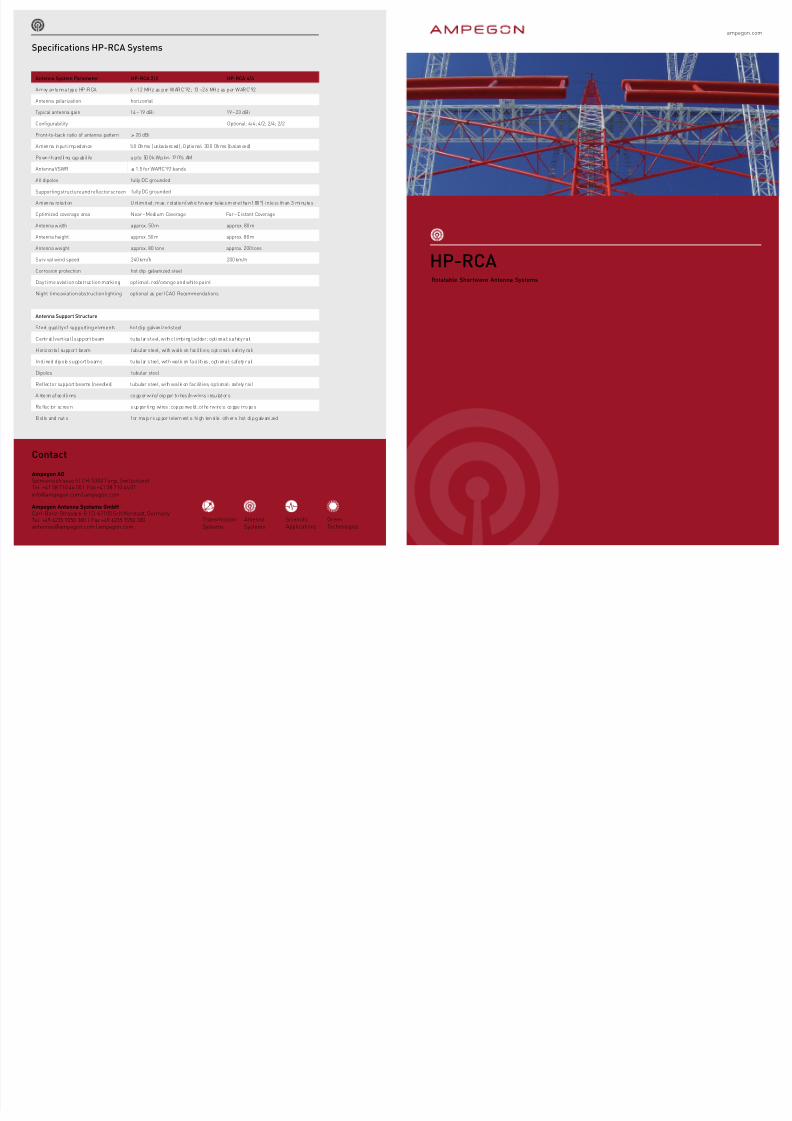
Ampegon | HP-RCA HP-RCA | Ampegon
Rotatable Shortwave Antenna Systems
ampegon.com
Ampegon AG
Spinnereistrasse 5 | CH-5300 Turgi, SwitzerlandTel. +41 58 710 44 00 | Fax +41 58 710 44 [email protected] | ampegon.com
Ampegon Antenna Systems GmbH
Carl-Benz-Strasse 6-8 | D-67105 Schierstadt, GermanyTel. +49 6235 9250 300 | Fax +49 6235 9250 [email protected] | ampegon.com
Contact
AntennaSystems
TransmissionSystems
ScientifcApplications
GreenTechnologies
HP-RCA
Antenna System Parameter HP-RCA 2/2 HP-RCA 4/4
Array antenna type HP-RCA 6 – 12 MHz as per WARC’92; 13 – 26 MHz as per WARC’92
Antenna polarization horizontal
Typical antenna gain 14 – 19 dBi 19 – 23 dBi
Confgurability Optional: 4/4; 4/2; 2/4; 2/2
Front-to-back ratio o antenna pattern > 20 dBi
Antenna input impedance 50 Ohms (unbalanced); Opt ional: 300 Ohms (balanced)
Po we r h and li ng cap ab il ity u p to 50 0 k W p lus 12 0 % AM
Antenna VSWR ≤ 1.5 or WARC‘92 bands
All dipoles ully DC grounded
Supporting structure and refector screen ully DC grounded
A nt en na ro ta tion Unl im it ed ; m ax . r ot at io n (wh ic h n ev er ta ke s m or e t ha n 180°) in le ss th an 3 minu te s
Optimized coverage area Near – Medium Coverage Far – Distant Coverage
Antenna width approx. 50 m approx. 80 m
Antenna height approx. 50 m approx. 80 m
Antenna weight approx. 80 tons approx. 200 tons
Survival wind speed 240 km/h 200 km/h
Corrosion protection hot dip galvanized steel
Day time aviation obstruction marking optional: red/orange and white paint
Night time aviation obstruction lighting optional as per ICAO Recommendations
Antenna Support Structure
Steel quality o supporting elements hot dip galvanized steel
Central (vertical) support beam tubular steel, with climbing ladder; optional: saety rail
Horizonta l support beam tubular steel , with walk on ac il it ies; opt ional: saety ra il
Inclined dipole support beams tubular steel, with walk on acilities; optional: saety rail
Dipoles tubular steel
Reector support beams (needles) tubular steel, with walk on acilities; optional: saety rail
A nte nn a ee d li nes co pp er w ire/ cop per tu bes /lo w loss i nsu lat or s
Re ec tor sc ree n s up por ti ng wi res : cop pe rwe ld ; ot he r w ire s: co ppe r ro pe s
B ol ts and nut s or ma jo r s up por t elem ent s: hi gh ten si le. oth er s: hot di p g alv ani zed
Specifcations HP-RCA Systems
7/27/2019 ALLISS Antenna Transmission System for Shortwave Broacast
http://slidepdf.com/reader/full/alliss-antenna-transmission-system-for-shortwave-broacast 2/2
Ampegon | HP-RCA HP-RCA | Ampegon
One o the master pieces in the history o antennadesign is the Ampegon rotatable shortwave antenna
system. Introduced in the 1980’s, the high peror-mance rotatable curtain array revolutionized theindustry and is still the most versatile, powerul andefcient system o its kind. This unique antenna sys-tem provides broadcasters with the shortest leadtime to start o exible worldwide national and inter-national coverage.
Based on a rigid dipole array and a tubular shat,the HP-RCA system is a back-to-back arrangemento a low band and a high band curtain antennaequipped with a reector screen. The system coversall shortwave broadcast bands rom 6 – 26 MHz androtates at the touch o a fnger-tip. Even though therotation is unlimited, under operational conditions theantenna does not need to rotate more than a maximumo 180° in one direction. This can be accomplished inless than 3 minutes.
The New HP-RCA 4/4With an overall weight o approximately 200 tons, thelegendary HP-RCA 4/4 needs a ground surace witha radius o less than 40 m to operate to any azimuth.
Efciency:Responding to the growing demand on increasedefciency and quicker payback, Ampegon has nowre-designed the classical HP-RCA 4/4 antenna,optimizing the system or ar distant coverage.Combining the advantages o the Ampegon rigidrotatable antenna design with those o the balancedRF eed line, the newest model HP-RCA 4/4 antennaeatures increased bandwidth, greater reliability,enhanced ease o assembly, improved efciency andsignifcant economic advantages. By optimizing theconfgurability or ar distant coverage, the complexswitching and tuning system in the tubular shatwas replaced with an evolutionary balanced eed
system. This not only reduces considerably thecost o the antenna, but also eliminates the needo additional balun and transormation lines. Thecoaxial line passing through the pivot bearingshas been upgraded by a twisting balanced eeder.In combination with a switch, this eeder allowsunlimited rotation o the antenna in any direction.
Confgurability:As a high end option the confgurable HP-RCA 4/4oers ultimate exibility not only in azimuthal di rectionbut also in shaping the radiation characteristic tomatch the desired coverage area. Patterns accordingto AHR 2/2, AHR 2/4 and AHR 4/4 array confgurationscan be chosen or the complete requency range othis antenna system.
HP-RCA 2/2In 2006, Ampegon introduced the HP-RCA 2/2
shortwave antenna system designed or near andmedium range coverage in analog AM or digital DRMmodes. The HP-RCA 2/2 helps broadcasters withlimited space and budget to make important powersavings while increasing considerably their coverageexibility. The Ampegon HP-RCA 2/2 is a highlyinteresting alternative system solution or broadbandfxed curtain antenna confgurations.
The HP-RCA 2/2 services similar coverage areas asthe classical LPD (log periodic dipole antenna) withup to 45 % higher efciency o the radiated power intoa defned target area. The ootprint o this poweruland highly exible system is surprisingly small. Withdimensions o 51 m x 51 m (W x H), the oundationsurace needs less than 12 m x 12 m. The neededground surace or the unlimited operation o theantenna has a radius o approximately 25 m.
Leading antenna technology designed to meet high demandson lexibility, reliability and cost-eicient operation
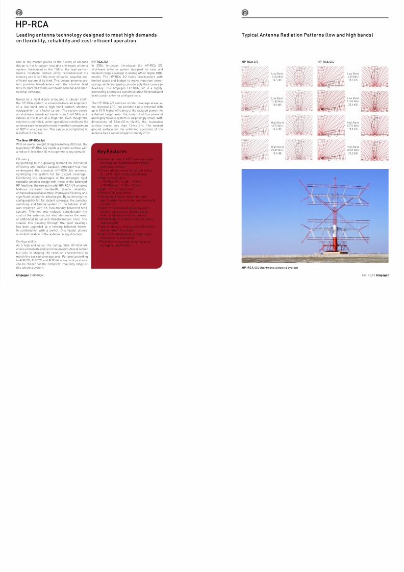
Typical Antenna Radiation Patterns (low and high bands)
HP-RCA
HP-RCA 4/4 shortwave antenna system
Key Features
• Rotates to cover a 360° coverage angleor complete exibility with a singleantenna structure
• Covers all shortwave broadcast bands(6 – 26 MHz) with only one antenna
• High antenna gain– HP-RCA 2/2: 14 dBi – 19 dBi– HP-RCA 4/4: 19 dBi – 23 dBi
• High ront-to-back ratio• Perect DC grounding• Sturdy rigid dipole design or sae
operation under extreme environmentalconditions
• System maintainability (no guy wire
system, easy access to main parts,minimized number o insulators)
• Small ootprint enables reduced spacerequirements
• Special design allows quick installationand minimum oundation
• Full DRM compatibility to meet uturedevelopments and needs
• Flexibility in coverage range by arrayconfguration RCA 4/4
HP-RCA 2/2 HP-RCA 4/4
Low Band6.05 MHz14.5 dBi
Low Band11.85 MHz18.5 dBi
High Band13,72 MHz14.6 dBi
High Band25,89 MHz18.5 dBi
Low Band6.05 MHz18,7 dBi
Low Band11.85 MHz
23,4 dBi
High Band13,72 MHz
18,8 dBi
High Band25,89 MHz
23,2 dBi