Embed Size (px)
Citation preview
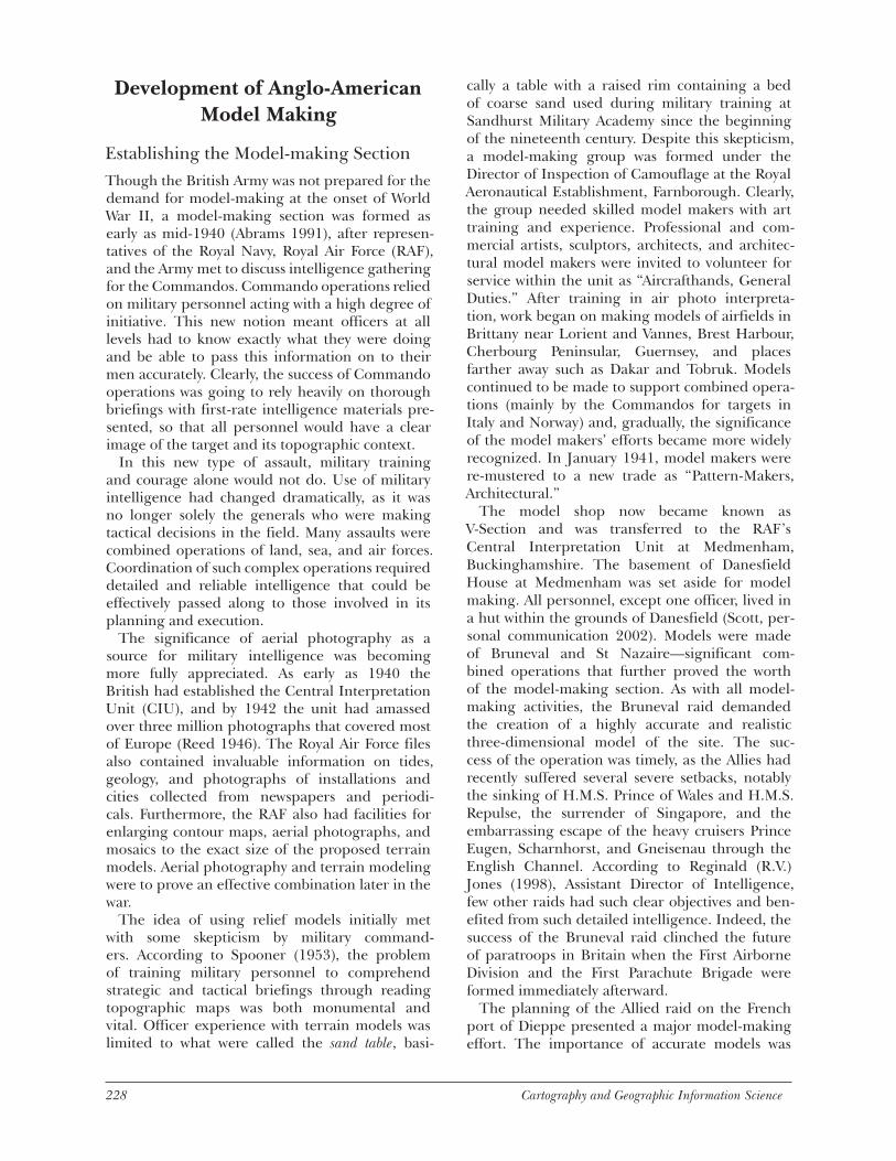
Allied Military Model Making during World War II
Alastair W. PearsonABSTRACT: It is generally accepted that the three-dimensional nature of the digital terrain model enhances our visualization of surfaces. Modern techniques enable a detailed landscape to be constructed as a facsimile of reality that provides an opportunity to move through or fly over the landscape. Given these benefits, it is little surprise that simulations using digital terrain models are employed as essential visual aids for briefing and training military personnel prior to land, air, and sea operations. Though these capabilities are significant, they are not necessarily, in the basic sense, new. This paper traces the development and examines the role of terrain models made by the Allies during World War II, a period prior to the development of computer-based modeling. Though made from basic materials, these sophisticated terrain models were hand crafted by enlisted sculptors, architects, stage designers, and artists, who carefully modeled a sculpture of the landscape to be an invaluable aid during key military operations of World War II.
KEYWORDS: Military mapping, terrain modeling, World War II
Introduction
Use of terrain models to support military operations has a long history and is by no means purely an artifact of the twen-
tieth century. According to Isabell Warmoes (1999), the production of scale models of fortified towns is a European tradition dating from the early six-teenth century. The Musée des plans-reliefs in Paris holds a collection of one hundred models of forti-fied towns situated along former French frontiers or subject to French rule that represent “portraits in relief ” of towns and their surrounding coun-tryside within range of artillery fire and enemy approach works, such as trenches, in case of siege. The levels of craftsmanship and attention to detail have seldom been exceeded.
During the twentieth century the three-dimen-sional terrain model played a significant role in many theatres of both world wars. According to Archibald Clough (1952), the static nature of World War I (1914-1918) demanded relief models of enemy defense positions for planning offensive assault operations. Campaign maps at a scale of 1:20,000 were made of the Western Front by a new model-making subdivision of the Ordnance Survey for General Headquarters in France.
Alastair Pearson is a principal lecturer at the University of Portsmouth, Department of Geography, Buckingham Building, Lion Terrace, Portsmouth, Hampshire, United Kingdom,PO13HE. E-mail: [email protected]>.
Cartography and Geographic Information Science, Vol. 29, No. 3, 2002, pp. 227-241
Layers of cardboard were cut to the shape of the contour, then pasted together and covered by a map sheet of the area printed on special paper, with the latest positions of the trenches marked. According to Peter Chasseaud (1999), models were sent to France between December 1916 and April 1917 at a rate of 36 per week. Indeed, by the end of the war, the Ordnance Survey had produced approximately one thousand of these models (War Office 1920).
A model of Zeebrugge, Belgium, at a scale of 1:2,500, made in 1918 by the Royal Navy, marked both a change in the nature of warfare and, as a consequence, a change in the requirements for ter-rain models. The famous Zeebrugge Raid of April 23, 1918, a daring attempt to destroy a U-boat base (Keegan 1998), required careful planning and briefing. Use of the terrain model during the preparation and planning stages of the Zeebrugge raid pointed to the future role of models during World War II for combined operations.
Between the wars, however, the utility of models to aid in terrain visualization was not entirely for-gotten and was alive immediately prior to World War II. In the second edition of A Key to Maps (1939), Harold Winterbotham added an entire chapter on model making to his earlier edition of 1937. Winterbotham, a brigadier and ex-Director General of the Ordnance Survey, had extensive combat experience in the Boer War and World War I, and had made models himself. Similarly, Frank Debenham’s Exercises in Cartography, published in 1937, devotes a chapter to the subject.
228 Cartography and Geographic Information Science Vol. 29, No. 3 229
Development of Anglo-American Model Making
Establishing the Model-making SectionThough the British Army was not prepared for the demand for model-making at the onset of World War II, a model-making section was formed as early as mid-1940 (Abrams 1991), after represen-tatives of the Royal Navy, Royal Air Force (RAF), and the Army met to discuss intelligence gathering for the Commandos. Commando operations relied on military personnel acting with a high degree of initiative. This new notion meant officers at all levels had to know exactly what they were doing and be able to pass this information on to their men accurately. Clearly, the success of Commando operations was going to rely heavily on thorough briefings with first-rate intelligence materials pre-sented, so that all personnel would have a clear image of the target and its topographic context.
In this new type of assault, military training and courage alone would not do. Use of military intelligence had changed dramatically, as it was no longer solely the generals who were making tactical decisions in the field. Many assaults were combined operations of land, sea, and air forces. Coordination of such complex operations required detailed and reliable intelligence that could be effectively passed along to those involved in its planning and execution.
The significance of aerial photography as a source for military intelligence was becoming more fully appreciated. As early as 1940 the British had established the Central Interpretation Unit (CIU), and by 1942 the unit had amassed over three million photographs that covered most of Europe (Reed 1946). The Royal Air Force files also contained invaluable information on tides, geology, and photographs of installations and cities collected from newspapers and periodi-cals. Furthermore, the RAF also had facilities for enlarging contour maps, aerial photographs, and mosaics to the exact size of the proposed terrain models. Aerial photography and terrain modeling were to prove an effective combination later in the war.
The idea of using relief models initially met with some skepticism by military command-ers. According to Spooner (1953), the problem of training military personnel to comprehend strategic and tactical briefings through reading topographic maps was both monumental and vital. Officer experience with terrain models was limited to what were called the sand table, basi-
cally a table with a raised rim containing a bed of coarse sand used during military training at Sandhurst Military Academy since the beginning of the nineteenth century. Despite this skepticism, a model-making group was formed under the Director of Inspection of Camouflage at the Royal Aeronautical Establishment, Farnborough. Clearly, the group needed skilled model makers with art training and experience. Professional and com-mercial artists, sculptors, architects, and architec-tural model makers were invited to volunteer for service within the unit as “Aircrafthands, General Duties.” After training in air photo interpreta-tion, work began on making models of airfields in Brittany near Lorient and Vannes, Brest Harbour, Cherbourg Peninsular, Guernsey, and places farther away such as Dakar and Tobruk. Models continued to be made to support combined opera-tions (mainly by the Commandos for targets in Italy and Norway) and, gradually, the significance of the model makers’ efforts became more widely recognized. In January 1941, model makers were re-mustered to a new trade as “Pattern-Makers, Architectural.”
The model shop now became known as V-Section and was transferred to the RAF’s Central Interpretation Unit at Medmenham, Buckinghamshire. The basement of Danesfield House at Medmenham was set aside for model making. All personnel, except one officer, lived in a hut within the grounds of Danesfield (Scott, per-sonal communication 2002). Models were made of Bruneval and St Nazaire—significant com-bined operations that further proved the worth of the model-making section. As with all model-making activities, the Bruneval raid demanded the creation of a highly accurate and realistic three-dimensional model of the site. The suc-cess of the operation was timely, as the Allies had recently suffered several severe setbacks, notably the sinking of H.M.S. Prince of Wales and H.M.S. Repulse, the surrender of Singapore, and the embarrassing escape of the heavy cruisers Prince Eugen, Scharnhorst, and Gneisenau through the English Channel. According to Reginald (R.V.) Jones (1998), Assistant Director of Intelligence, few other raids had such clear objectives and ben-efited from such detailed intelligence. Indeed, the success of the Bruneval raid clinched the future of paratroops in Britain when the First Airborne Division and the First Parachute Brigade were formed immediately afterward.
The planning of the Allied raid on the French port of Dieppe presented a major model-making effort. The importance of accurate models was
228 Cartography and Geographic Information Science Vol. 29, No. 3 229
brought home to the section after the raid. The model makers were told that the sea wall, shown on the model as being high enough to provide cover for the tanks on the beach, did not provide cover, thereby leaving tanks and other armor exposed to German artillery fire (Abrams 1991). But few tanks made it that far, and the sea wall was the only known error in the entire model, which saved many lives.
The work of the model-making section began to gain recognition by all three services. V-Section gained a reputation for integrity and worthwhile contributions to intelligence gathering and use. Consequently the workload in the model-making section increased, and more personnel were required.
Expansion of V-SectionRepresentatives of the Combined Chiefs of Staff decided as early as February 1942 that terrain models should be employed in the planning and briefing of major operations. When the U.S. Eighth Army Air Force came to Britain, the Air Ministry looked to the Americans to provide additional model-making capacity. An Engineer Model-Making Detachment, which arrived in July 1942 with one officer and twenty men, increased by the end of the year to three officers and 85 men. Shortly after they arrived, the Americans were moved to Henley-on-Thames, just beside the river a few miles away, to what had been an exclusive private club called Phyllis Court (Abrams 1991). Royal Air Force personnel remained at Danesfield and were transported to Phyllis Court by truck or made their own way there by bicycle. Phyllis Court, a regency country house with fine views of the River Thames through its large French windows, was a pleasant place to work. Spacious and well lit, it was conducive to model making (Scott, personal communication 2002).
After a short training course at Nuneham Harcourt, south of Oxford, the Americans joined up with the RAF model-making team to form a
“powerful allied group which, during the course of the war, turned out a remarkably fine series of models in wide variety” (Clough 1952, p. 556). Oddly, the Americans were hitherto unfamiliar with the interpretation of air photography, par-ticularly the use of photogrammetry for intelli-gence gathering (Reed 1946). A great many of the American generals required much convincing and training about the uses of air photos for gathering intelligence. In Britain, by contrast, aerial photo-graph interpretation had become a basic source of intelligence, and the use of air photography rep-
resented a major British contribution to the Allied intelligence effort.
V-Section moved from Henley back to Danesfield House, Medmenham, Buckinghamshire, in the summer of 1943, apparently due to the increased demand for models. Invasion plans for the Sicilian and Normandy coasts dominated the work of the Model-Making Detachment. A model of the island of Pantelleria, near Sicily, was made in the United States and sent over in October 1942. Models were also prepared for air attacks on the dams at Eder, Sorpe, Möhne, and Bisorte, the ball-bearing works at Schweinfurt, the viaducts at Bielefeld and Neuenbecke, oil refineries at Ploesti, the ship lift at Magdeburg, and many others, plus various targets for South East Asia Command. Later on, the unit supplied models of the experimental V-weapon sites at Peenemünde and launching sites at Bois Carré, Watten, Siracourt, and Wizernes.
American model-making detachments worked in North Africa and Italy, under the control of the Director of Survey at Allied Forces Headquarters. Although the effort focused on the preparation of models for the assault on the south coast of France, a model-making detachment served in Italy with the U.S. Fifth Army, and a model-making section was attached to the Middle East Interpretation Unit in Cairo. In May 1943, another British detachment accompanied the Mediterranean Allied Photo Reconnaissance Wing to La Marsa, Tunisia, where models of the Italian beachheads were made, and then proceeded to San Severo, Italy, in December of the same year. Models were made of areas of eastern Italy, including those used for the crossing of the River Sangro by the British Eighth Army under Montgomery (Scott, personal communication 2002).
The Allied team at Medmenham broke up in August 1944 when the Americans decided to send their personnel overseas to be closer to the actual operations. The Model-Making Detachment moved to Paris, where it was set up as an inde-pendent unit under the control of the Engineer Intelligence Division. Models were produced for assisting in the assault on the Siegfried Line, the crossing of the Rhine, and the thrust into Germany. Models of the forts at Metz, which held out for some time after the town had fallen to the Allies, were apparently very useful in the forts’ final capture.
Model Construction TechniquesThere were two main methods of model construc-tion: the photo-skinned method and the egg-crate
230 Cartography and Geographic Information Science Vol. 29, No. 3 231
method. Both methods are described in detail by Harrison Reed (1946) and by the Air Ministry in its Handbook on Models and Model-making, first pub-lished in May 1943.
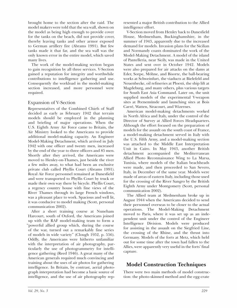
The Photo-skinned MethodBritish and Americans worked closely to meet very tight deadlines. As a rule, two British “Pattern Makers, Architectural” worked side by side with two U.S. Army “Model Makers” on the same shift and on the same part of the construction. The basement at Medmenham must have echoed to the sound of fret saws and hammers as the con-tours that had been traced from enlarged maps were cut out of hardboard and then mounted and nailed into position. After the contours were smoothed by electric chisel, the landform was given an unbroken surface by the application with spatulas of Watertex, a mixture of plaster of Paris, glue size, and wood pulp. Frequent and careful ref-erence to the original maps was an essential part of the process. Re-scaled photographs were then dampened so that they could be stretched and placed carefully over the model. Then the model was painted to match the colors of the landscape, and miniature buildings, trees, and fences were added. Color tones were transparent so that the field patterns and texture of the terrain surface as revealed by the photo-skin could show through. Hedging, an important feature in the European landscape, was added using a green paste mixture forced through a nozzle by controlled air pressure. For large-scale models, buildings were crafted in linoleum, which was cut to shape with razor blades. When the model makers were finished, planners could study the model and prepare for their assault or bombing raid.
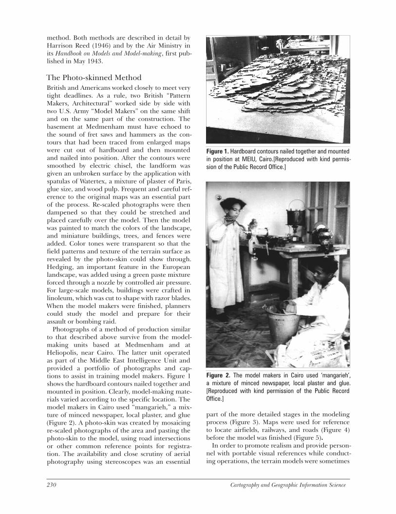
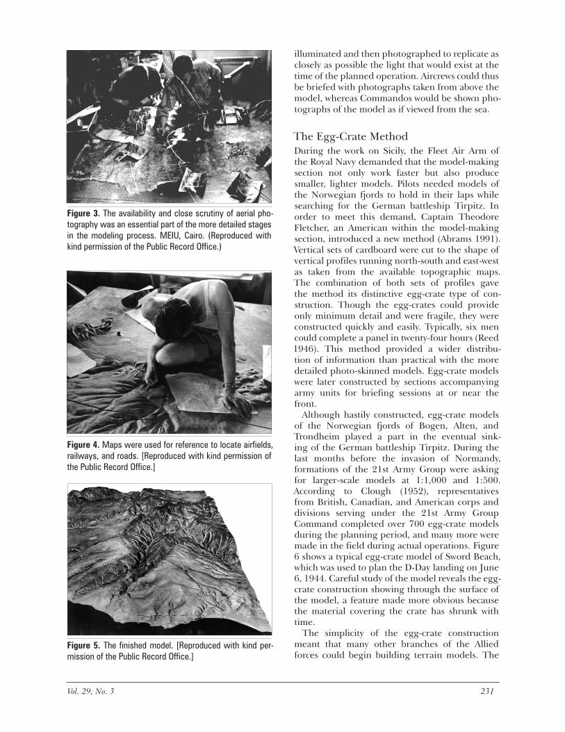
Photographs of a method of production similar to that described above survive from the model-making units based at Medmenham and at Heliopolis, near Cairo. The latter unit operated as part of the Middle East Intelligence Unit and provided a portfolio of photographs and cap-tions to assist in training model makers. Figure 1 shows the hardboard contours nailed together and mounted in position. Clearly, model-making mate-rials varied according to the specific location. The model makers in Cairo used “mangarieh,” a mix-ture of minced newspaper, local plaster, and glue (Figure 2). A photo-skin was created by mosaicing re-scaled photographs of the area and pasting the photo-skin to the model, using road intersections or other common reference points for registra-tion. The availability and close scrutiny of aerial photography using stereoscopes was an essential
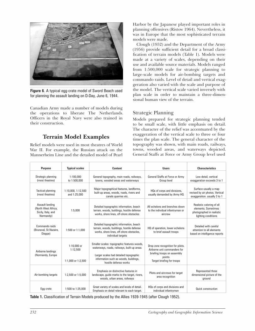
part of the more detailed stages in the modeling process (Figure 3). Maps were used for reference to locate airfields, railways, and roads (Figure 4) before the model was finished (Figure 5).
In order to promote realism and provide person-nel with portable visual references while conduct-ing operations, the terrain models were sometimes
Figure 1. Hardboard contours nailed together and mounted in position at MEIU, Cairo.[Reproduced with kind permis-sion of the Public Record Office.]
Figure 2. The model makers in Cairo used ‘mangarieh’, a mixture of minced newspaper, local plaster and glue. [Reproduced with kind permission of the Public Record Office.]
230 Cartography and Geographic Information Science Vol. 29, No. 3 231
illuminated and then photographed to replicate as closely as possible the light that would exist at the time of the planned operation. Aircrews could thus be briefed with photographs taken from above the model, whereas Commandos would be shown pho-tographs of the model as if viewed from the sea.
The Egg-Crate MethodDuring the work on Sicily, the Fleet Air Arm of the Royal Navy demanded that the model-making section not only work faster but also produce smaller, lighter models. Pilots needed models of the Norwegian fjords to hold in their laps while searching for the German battleship Tirpitz. In order to meet this demand, Captain Theodore Fletcher, an American within the model-making section, introduced a new method (Abrams 1991). Vertical sets of cardboard were cut to the shape of vertical profiles running north-south and east-west as taken from the available topographic maps. The combination of both sets of profiles gave the method its distinctive egg-crate type of con-struction. Though the egg-crates could provide only minimum detail and were fragile, they were constructed quickly and easily. Typically, six men could complete a panel in twenty-four hours (Reed 1946). This method provided a wider distribu-tion of information than practical with the more detailed photo-skinned models. Egg-crate models were later constructed by sections accompanying army units for briefing sessions at or near the front.
Although hastily constructed, egg-crate models of the Norwegian fjords of Bogen, Alten, and Trondheim played a part in the eventual sink-ing of the German battleship Tirpitz. During the last months before the invasion of Normandy, formations of the 21st Army Group were asking for larger-scale models at 1:1,000 and 1:500. According to Clough (1952), representatives from British, Canadian, and American corps and divisions serving under the 21st Army Group Command completed over 700 egg-crate models during the planning period, and many more were made in the field during actual operations. Figure 6 shows a typical egg-crate model of Sword Beach, which was used to plan the D-Day landing on June 6, 1944. Careful study of the model reveals the egg-crate construction showing through the surface of the model, a feature made more obvious because the material covering the crate has shrunk with time.
The simplicity of the egg-crate construction meant that many other branches of the Allied forces could begin building terrain models. The
Figure 3. The availability and close scrutiny of aerial pho-tography was an essential part of the more detailed stages in the modeling process. MEIU, Cairo. (Reproduced with kind permission of the Public Record Office.)
Figure 4. Maps were used for reference to locate airfields, railways, and roads. [Reproduced with kind permission of the Public Record Office.]
Figure 5. The finished model. [Reproduced with kind per-mission of the Public Record Office.]
232 Cartography and Geographic Information Science Vol. 29, No. 3 233
Canadian Army made a number of models during the operations to liberate The Netherlands. Officers in the Royal Navy were also trained in their construction.
Terrain Model ExamplesRelief models were used in most theatres of World War II. For example, the Russian attack on the Mannerheim Line and the detailed model of Pearl
Harbor by the Japanese played important roles in planning offensives (Ristow 1964). Nevertheless, it was in Europe that the most sophisticated terrain models were made.
Clough (1952) and the Department of the Army (1956) provide sufficient detail for a broad classi-fication of terrain models (Table 1). Models were made at a variety of scales, depending on their use and available source materials. Models ranged from 1:500,000 scale for strategic planning to large-scale models for air-bombing targets and commando raids. Level of detail and vertical exag-geration also varied with the scale and purpose of the model. The vertical scale varied inversely with plan scale in order to maintain a three-dimen-sional human view of the terrain.
Strategic PlanningModels prepared for strategic planning tended to be small scale, with little emphasis on detail. The character of the relief was accentuated by the exaggeration of the vertical scale to three or four times the plan scale. The general character of the topography was shown, with main roads, railways, towns, wooded areas, and waterways depicted. General Staffs at Force or Army Group level used
Figure 6. A typical egg-crate model of Sword Beach used for planning the assault landing on D-Day, June 6, 1944.
Purpose Typical scales Content Users Characteristics
Strategic planning(most theatres)
1:100,000 to 1:500,000
General topography, main roads, railways, towns, wooded areas and waterways
General Staffs at Force or Army Group level
Low detail, vertical exaggeration exceeds 3 to 1
Tactical planning(most theatres)
1:10,000, 1:12,500 and 1:25,000
Major topographical features, landforms, built-up areas, woods, roads, rivers and
canals quarries etc.
HQs of corps and divisions, usually demanded by Army HQ
Surface usually a map revised by air photos. Vertical exaggeration. usually 3 to 1
Assault landing(North West Africa,
Sicily, Italy, and Normandy)
1:5,000Detailed topographic information, beach terrain, woods, buildings, hostile defense works, shore lines, off-shore obstacles
All echelons and branches down to the individual infantryman or
aircrew
Realistic coloring of all elements. Sometimes
photographed in realistic lighting conditions
Commando raids(Bruneval, St.Nazaire,
Dieppe)1:500 or 1:1,000
Detailed topographic information, beach terrain, woods, buildings, hostile defense works, shore lines, off-shore obstacles,
individual targets
HQ of operation, lower echelons to brief assault troops
Detailed with careful attention to all elements
based on intelligence reports
Airborne landings(Normandy, Europe
1:10,000 or 1:12,500
1:1,000 or 1:2,500
Smaller scales: topographic features woods, waterways, roads, railways, built-up areas
Larger scales had detailed topographic information such as woods, buildings,
hostile defense works
Drop zone recognition for pilots. Airborne unit commanders for briefing troops on assembly
points Target briefing for troops
Air-bombing targets 1:2,500 or 1:5,000Emphasis on distinctive features in
landscape, guide marks to the target, rivers, woods, urban areas, railways
Pilots and aircrews for target area recognition
Represented three dimensional picture of the
ground
Egg-crate 1:500 to 1:25,000Great variety of scales and levels of detail. Emphasis on detail relevant to each target.
HQs of corps and divisions and individual infantrymen
Quick construction
Table 1. Classification of Terrain Models produced by the Allies 1939-1945 (after Clough 1952).

232 Cartography and Geographic Information Science Vol. 29, No. 3 233
these models for general planning. Figure 7 shows an example of this type of model. The United States Staff (Research and Analysis Branch, Office of Strategic Services) prepared this relief map at Supreme Headquarters of Allied Expeditionary Forces. This particular model was used in the Cabinet War Room in Whitehall and accompanied Winston Churchill at all the meetings and conferences with President Roosevelt and Soviet political leader Stalin.
Air Bombing TargetsModels for aerial bombing were typically con-structed at scales between 1:2,500 and 1:5,000—large enough to accommodate reasonably detailed elevations of buildings and give pilots and navi-gators a representative three-dimensional picture of the target and surrounding terrain. Special emphasis was placed on distinguishing features and points of recognition that served as guiding marks for navigation to the target. In precision bombing, accuracy of representation was essential. Depiction of side elevations of buildings was cru-
cial in enabling pilots to recognize a specific navi-gation mark or target. Missing the target would mean failure of the mission and unnecessary loss of civilian lives. Several models that survived the war were used to support such operations, the most famous of which was the Dambuster Raid of May 1943.
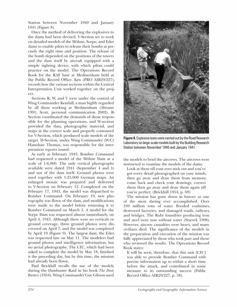
The Dambuster RaidIn this famous episode of World War II the British engineer Barnes Wallis devised a scheme to destroy several large dams on the upper Rhine that, if breached, would disrupt factory produc-tion in the Rhine Valley. It was hoped that the raid would also provide a significant morale boost to the Allies. The raid was very dangerous because a five-ton bomb had to be dropped at low altitude so that it could skip across the water to an exact spot next to the dam, where it would sink and explode deep under the surface. Plans for such a raid were started quite early in the war. Explosive tests were carried out by the Road Research Laboratory on large-scale models built by the Building Research
Figure 7. Relief map of northern Italy prepared by the United States staff [Research and Analysis Branch, Office of Strategic Services at Supreme Headquarters of Allied Expeditionary Forces (SHAEF)].
234 Cartography and Geographic Information Science Vol. 29, No. 3 235
Station between November 1940 and January 1941 (Figure 8).
Once the method of delivering the explosives to the dams had been devised, V-Section set to work on detailed models of the Möhne, Sorpe, and Eder dams to enable pilots to release their bombs at pre-cisely the right time and position. The release of the bomb depended on the positions of the towers and the dam itself by aircraft equipped with a simple sighting device, with which pilots could practice on the model. The Operations Record Book for the RAF base at Medmenham held at the Public Record Office, Kew (PRO AIR29/227), records how the various sections within the Central Interpretation Unit worked together on the proj-ect.
Sections R, W, and V were under the control of Wing Commander Kendall, a man highly regarded by all those working at Medmenham (Abrams 1991; Scott, personal communication 2002). R-Section coordinated the demands of those respon-sible for the planning operations, and W-section provided the data, photographic material, and maps at the correct scale and properly contoured for V-Section, which produced scale models of the target. D-Section, under Wing Commander (W/C) Hamshaw Thomas, was responsible for the inter-pretation reports issued.
As early as February 1943, Bomber Command had requested a model of the Möhne Dam at a scale of 1:6,000. The only vertical photographs available were dated 1941 (September 4 and 5) and not of the dam itself. Ground photos were used together with 1:25,000 German maps. An enlarged mosaic was prepared and delivered to V-Section on February 12. Completed on the February 17, 1943, the model was dispatched to Bomber Command. On February 19, new pho-tography was flown of the dam, and modifications were made to the model before returning it to Bomber Command on March 3. A model for the Sorpe Dam was requested almost immediately, on April 4, 1943. Although there were no verticals or ground coverage, three ground photos were dis-covered on April 7, and the model was completed by April 19 (Figure 9). The largest dam, the Eder, was requested late on May 11. The modelers had ground photos and intelligence information, but no aerial photography. The CIU, which had been asked to complete the model by May 18, finished it the preceding day, but by this time, the mission had already been flown.
Paul Brickhill recalls the use of the models during the Dambuster Raid in his book The Dam Busters (1954). Wing Commander Guy Gibson used
the models to brief the aircrews. The aircrews were instructed to examine the models of the dams:
Look at these till your eyes stick out and you’ve got every detail photographed on your minds, then go away and draw them from memory, come back and check your drawings, correct them then go away and draw them again till you’re perfect. (Brickhill 1954, p. 69) The mission has gone down in history as one
of the most daring ever accomplished. Over 330 million tons of water flooded coalmines, destroyed factories, and damaged roads, railways, and bridges. The Ruhr foundries producing iron and steel were now without water (Staerck 1998). However, aircrew casualties were heavy, and many civilians died. The significance of the models in the preparation and execution of the mission was fully appreciated by those who took part and those who reviewed the results. The Operations Record Book states:
It will be seen, therefore, that this unit [CIU] was able to provide Bomber Command with precise information up to within a short time before the attack, and contributed in some measure to its outstanding success (Public Record Office AIR29/227, p. 38).
Figure 8. Explosive tests were carried out by the Road Research Laboratory on large-scale models built by the Building Research Station between November 1940 and January 1941.

234 Cartography and Geographic Information Science Vol. 29, No. 3 235
Precision Bombing RaidsAs World War II progressed, improvements in aircraft, munitions, and intelligence increased the capability of Allied air power to carry out precision bombing of small targets in towns and cities. However, precision bombing would have been impossible if aircrews could not recognize
the target or find their way to the target quickly. Thorough preparation was paramount because these raids were hazardous both to aircrews and noncombatants, and models were of utmost importance.
Several models used to brief crews prior to these sorties have survived. These include those prepared for the RAF’s April 1944 precision bombing raid on The Hague, in The Netherlands. The mission required high levels of precision. Its target, a ninety-foot building, housed the Central Population Registry, which included lists of Dutchmen marked for deportation. Briefing models were prepared at two scales: 1:1,190 and 1:6,250. The smaller-scale model was used to brief aircrews on how to approach and recognize the area of the target, and the larger-scale model was used to identify the target itself (Figure 10). These models clearly demonstrate the use of caricature in the detail of the target. By contrast, a general impression of detail and architectural style was sufficient for aircrews flying at high speed and low altitude. It was of vital importance that aircrews recognize the route, as the route was planned to prevent the Germans from guessing the target. The time was chosen to reduce the risk to civilians, and the buildings on both sides of the target had to be left untouched. Six Mosquito twin-engine fighter-bombers with delayed-action high explo-sives and incendiary bombs attacked at housetop level and completely destroyed the building. Accidental damage was also sustained by a nearby German Army barracks. The mission was a success, even though recognition of the route was made difficult by the flooding of surrounding farmland by the Germans.
Assault LandingModels prepared for assault landing were used for operation planning by all echelons and branches of the armed forces, and included information valuable to all users. The Navy required detailed depiction of shorelines, beaches, and offshore obstacles. The infantry required detailed repre-sentation of beach terrain, woods, buildings, and enemy defenses. Obstacles and salient features for controlling artillery fire were also needed. Such detail was also useful to the aircrews in identifying targets and drop zones.
Operation “Husky”: The Invasion of SicilyA model of Sicily, ordered by No.1 Planning Staff Middle East at a scale of 1:25,000, was to cover the area south from Mt. Etna to Pachino and west beyond Gela, the region of the proposed assault
Figure 9. Model of the Sorpe Dam, Germany.
Figure 10. The larger-scale model for identifying the target. Close observation of the model reveals a caricature of the building facade. Aircrews were unlikely to require more accuracy, given the high speed and low altitude of their flight.
236 Cartography and Geographic Information Science Vol. 29, No. 3 237
landings on Sicily. The models were constructed by the model-making section of the Middle East Interpretation Unit based at Cairo, using 1:25,000 and 1:50,000 Italian topographic maps and 1:250,000 air maps together with revisions provided by air photo interpretation. The model was made in ten sections, each measuring 14 feet by 16 feet. The relief maps were completed in two months and annotated with defenses and relevant mili-tary information. The western sections were then crated and sent to Algiers for use by the American Task Force. After operational planning was com-pleted, the remaining sections were flown to the First Airborne Division for briefing crews.
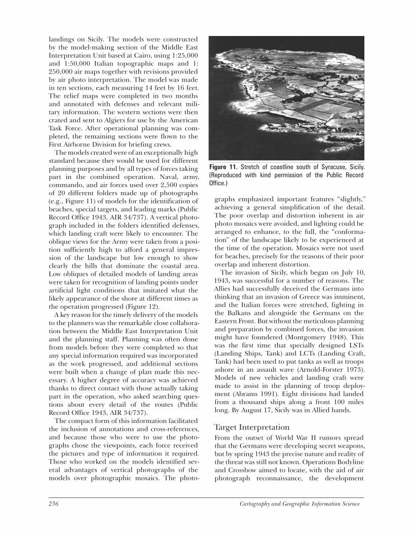
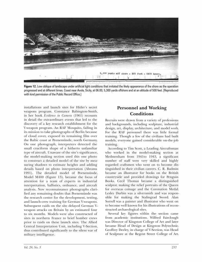
The models created were of an exceptionally high standard because they would be used for different planning purposes and by all types of forces taking part in the combined operation. Naval, army, commando, and air forces used over 2,500 copies of 20 different folders made up of photographs (e.g., Figure 11) of models for the identification of beaches, special targets, and leading marks (Public Record Office 1943, AIR 34/737). A vertical photo-graph included in the folders identified defenses, which landing craft were likely to encounter. The oblique views for the Army were taken from a posi-tion sufficiently high to afford a general impres-sion of the landscape but low enough to show clearly the hills that dominate the coastal area. Low obliques of detailed models of landing areas were taken for recognition of landing points under artificial light conditions that imitated what the likely appearance of the shore at different times as the operation progressed (Figure 12).
A key reason for the timely delivery of the models to the planners was the remarkable close collabora-tion between the Middle East Interpretation Unit and the planning staff. Planning was often done from models before they were completed so that any special information required was incorporated as the work progressed, and additional sections were built when a change of plan made this nec-essary. A higher degree of accuracy was achieved thanks to direct contact with those actually taking part in the operation, who asked searching ques-tions about every detail of the routes (Public Record Office 1943, AIR 34/737).
The compact form of this information facilitated the inclusion of annotations and cross-references, and because those who were to use the photo-graphs chose the viewpoints, each force received the pictures and type of information it required. Those who worked on the models identified sev-eral advantages of vertical photographs of the models over photographic mosaics. The photo-
graphs emphasized important features “slightly,” achieving a general simplification of the detail. The poor overlap and distortion inherent in air photo mosaics were avoided, and lighting could be arranged to enhance, to the full, the “conforma-tion” of the landscape likely to be experienced at the time of the operation. Mosaics were not used for beaches, precisely for the reasons of their poor overlap and inherent distortion.
The invasion of Sicily, which began on July 10, 1943, was successful for a number of reasons. The Allies had successfully deceived the Germans into thinking that an invasion of Greece was imminent, and the Italian forces were stretched, fighting in the Balkans and alongside the Germans on the Eastern Front. But without the meticulous planning and preparation by combined forces, the invasion might have foundered (Montgomery 1948). This was the first time that specially designed LSTs (Landing Ships, Tank) and LCTs (Landing Craft, Tank) had been used to put tanks as well as troops ashore in an assault wave (Arnold-Forster 1973). Models of new vehicles and landing craft were made to assist in the planning of troop deploy-ment (Abrams 1991). Eight divisions had landed from a thousand ships along a front 100 miles long. By August 17, Sicily was in Allied hands.
Target InterpretationFrom the outset of World War II rumors spread that the Germans were developing secret weapons, but by spring 1943 the precise nature and reality of the threat was still not known. Operations Bodyline and Crossbow aimed to locate, with the aid of air photograph reconnaissance, the development
Figure 11. Stretch of coastline south of Syracuse, Sicily. (Reproduced with kind permission of the Public Record Office.)
236 Cartography and Geographic Information Science Vol. 29, No. 3 237
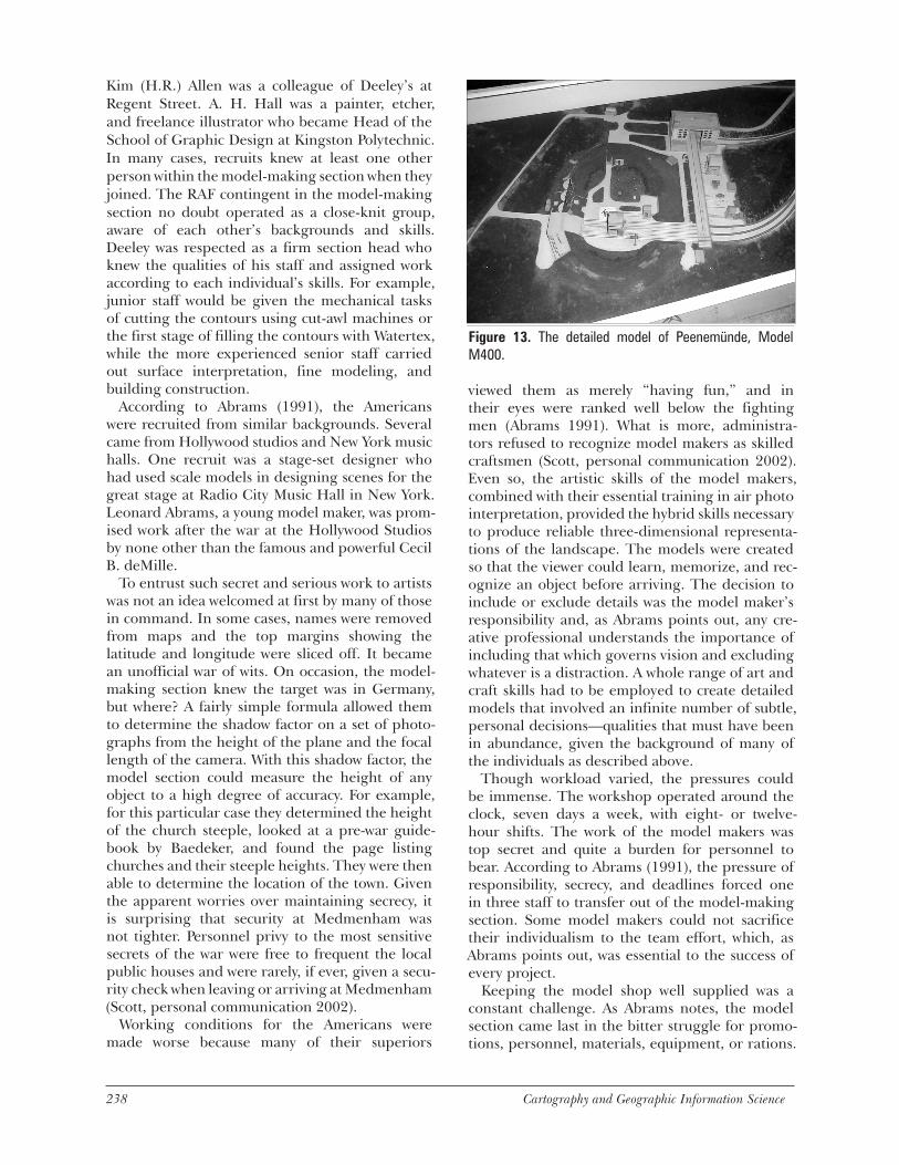
installations and launch sites for Hitler’s secret weapons program. Constance Babington-Smith, in her book Evidence in Camera (1961) recounts in detail the extraordinary events that led to the discovery of a key research establishment for the V-weapon program. An RAF Mosquito, failing in its mission to take photographs of Berlin because of cloud cover, exposed its remaining film over the Baltic coast at Peenemünde, north Germany. On one photograph, interpreters detected the small cruciform shape of a hitherto unfamiliar type of aircraft. Unaware of the site’s significance, the model-making section used this one photo to construct a detailed model of the site by mea-suring shadows to estimate heights and adding details based on photo interpretation (Abrams 1991). The detailed model of Peenemünde, Model M400 (Figure 13), became the focus of attention for a team of experts in industrial interpretation, ballistics, ordnance, and aircraft analysis. New reconnaissance photographs clari-fied any remaining doubts that Peenemünde was the research center for the development, testing, and launch-crew training for German V-weapons. Subsequent raids on the site delayed German V-weapon attacks on Britain by an estimated four to six months. Models were also constructed of sites in northern France to brief bomber crews prior to raids on these launch sites. The Allied Central Interpretation Unit, including V-Section, thus contributed significantly to the silent war of military intelligence.
Personnel and Working Conditions
Recruits were drawn from a variety of professions and backgrounds, including sculpture, industrial design, art, display, architecture, and model work. For the RAF personnel there was little formal training. Though a few of the civilians had built models, everyone gained considerable on-the-job training.
According to Tim Scott, a Leading Aircraftsman who worked in the model-making section at Medmenham from 1941to 1943, a significant number of staff were very skilled and highly regarded craftsmen who went on to become dis-tinguished in their civilian careers. C. R. Badmin became an illustrator for books on the British countryside and provided drawings for Penguin Books. Cecil Thomas became a distinguished sculptor, making the relief portraits of the Queen for overseas coinage and the Coronation Medal. Lesley Durbin was a silversmith and was respon-sible for making the Stalingrad Sword. Alan Sorrell was a painter and illustrator who went on to become well known for his illustrations of recon-structed archaeological sites.
Several key figures within the section came from academic institutions. Wilfred Fairclough was Director of Kingston College of Art and later became Head of Design at Kingston Polytechnic. Geoffrey Deeley, in charge of V-Section, was Head of Sculpture at the Regent Street College of Art.
Figure 12. Low oblique of landscape under artificial light conditions that imitated the likely appearance of the shore as the operation progressed and at different times. Coast near Avola, Sicily, at 06.00, 5,300 yards offshore and at an altitude of 500 feet. [Reproduced with kind permission of the Public Record Office.]
238 Cartography and Geographic Information Science Vol. 29, No. 3 239
Kim (H.R.) Allen was a colleague of Deeley’s at Regent Street. A. H. Hall was a painter, etcher, and freelance illustrator who became Head of the School of Graphic Design at Kingston Polytechnic. In many cases, recruits knew at least one other person within the model-making section when they joined. The RAF contingent in the model-making section no doubt operated as a close-knit group, aware of each other’s backgrounds and skills. Deeley was respected as a firm section head who knew the qualities of his staff and assigned work according to each individual’s skills. For example, junior staff would be given the mechanical tasks of cutting the contours using cut-awl machines or the first stage of filling the contours with Watertex, while the more experienced senior staff carried out surface interpretation, fine modeling, and building construction.
According to Abrams (1991), the Americans were recruited from similar backgrounds. Several came from Hollywood studios and New York music halls. One recruit was a stage-set designer who had used scale models in designing scenes for the great stage at Radio City Music Hall in New York. Leonard Abrams, a young model maker, was prom-ised work after the war at the Hollywood Studios by none other than the famous and powerful Cecil B. deMille.
To entrust such secret and serious work to artists was not an idea welcomed at first by many of those in command. In some cases, names were removed from maps and the top margins showing the latitude and longitude were sliced off. It became an unofficial war of wits. On occasion, the model-making section knew the target was in Germany, but where? A fairly simple formula allowed them to determine the shadow factor on a set of photo-graphs from the height of the plane and the focal length of the camera. With this shadow factor, the model section could measure the height of any object to a high degree of accuracy. For example, for this particular case they determined the height of the church steeple, looked at a pre-war guide-book by Baedeker, and found the page listing churches and their steeple heights. They were then able to determine the location of the town. Given the apparent worries over maintaining secrecy, it is surprising that security at Medmenham was not tighter. Personnel privy to the most sensitive secrets of the war were free to frequent the local public houses and were rarely, if ever, given a secu-rity check when leaving or arriving at Medmenham (Scott, personal communication 2002).
Working conditions for the Americans were made worse because many of their superiors
viewed them as merely “having fun,” and in their eyes were ranked well below the fighting men (Abrams 1991). What is more, administra-tors refused to recognize model makers as skilled craftsmen (Scott, personal communication 2002). Even so, the artistic skills of the model makers, combined with their essential training in air photo interpretation, provided the hybrid skills necessary to produce reliable three-dimensional representa-tions of the landscape. The models were created so that the viewer could learn, memorize, and rec-ognize an object before arriving. The decision to include or exclude details was the model maker’s responsibility and, as Abrams points out, any cre-ative professional understands the importance of including that which governs vision and excluding whatever is a distraction. A whole range of art and craft skills had to be employed to create detailed models that involved an infinite number of subtle, personal decisions—qualities that must have been in abundance, given the background of many of the individuals as described above.
Though workload varied, the pressures could be immense. The workshop operated around the clock, seven days a week, with eight- or twelve-hour shifts. The work of the model makers was top secret and quite a burden for personnel to bear. According to Abrams (1991), the pressure of responsibility, secrecy, and deadlines forced one in three staff to transfer out of the model-making section. Some model makers could not sacrifice their individualism to the team effort, which, as Abrams points out, was essential to the success of every project.
Keeping the model shop well supplied was a constant challenge. As Abrams notes, the model section came last in the bitter struggle for promo-tions, personnel, materials, equipment, or rations.
Figure 13. The detailed model of Peenemünde, Model M400.
238 Cartography and Geographic Information Science Vol. 29, No. 3 239
During the formative stages of the model-making section, model makers needed sculptor’s spatulas, artist’s brushes, and texturing materials. Because none of these items were listed in the RAF Supply Catalogue, personnel had to scrounge materials and equipment from their own studios or buy them out of their meager wages of one shilling per day. (Wages could be more, depending on rank and gender; women could expect two-thirds of a man’s pay.) The entire workforce was male to begin with, but as demand for models increased, recruit-ers began searching with some success for women volunteers.
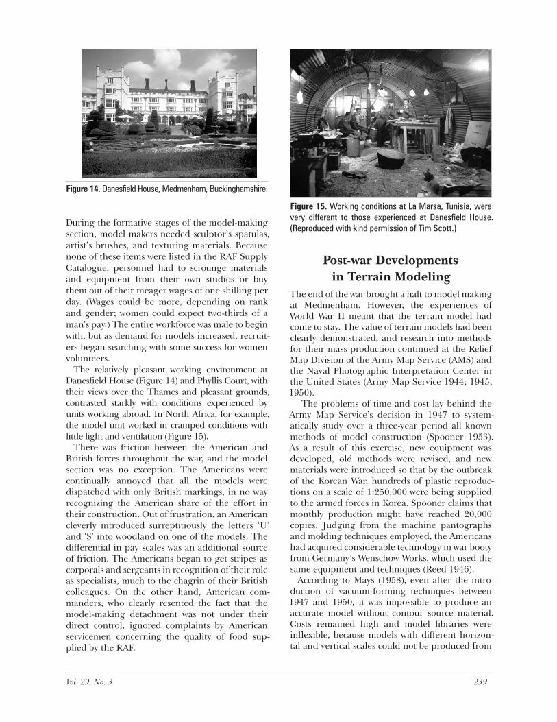
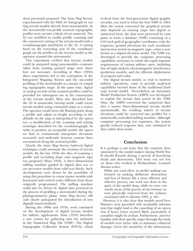
The relatively pleasant working environment at Danesfield House (Figure 14) and Phyllis Court, with their views over the Thames and pleasant grounds, contrasted starkly with conditions experienced by units working abroad. In North Africa, for example, the model unit worked in cramped conditions with little light and ventilation (Figure 15).
There was friction between the American and British forces throughout the war, and the model section was no exception. The Americans were continually annoyed that all the models were dispatched with only British markings, in no way recognizing the American share of the effort in their construction. Out of frustration, an American cleverly introduced surreptitiously the letters ‘U’ and ‘S’ into woodland on one of the models. The differential in pay scales was an additional source of friction. The Americans began to get stripes as corporals and sergeants in recognition of their role as specialists, much to the chagrin of their British colleagues. On the other hand, American com-manders, who clearly resented the fact that the model-making detachment was not under their direct control, ignored complaints by American servicemen concerning the quality of food sup-plied by the RAF.
Figure 15. Working conditions at La Marsa, Tunisia, were very different to those experienced at Danesfield House. (Reproduced with kind permission of Tim Scott.)
Post-war Developments in Terrain Modeling
The end of the war brought a halt to model making at Medmenham. However, the experiences of World War II meant that the terrain model had come to stay. The value of terrain models had been clearly demonstrated, and research into methods for their mass production continued at the Relief Map Division of the Army Map Service (AMS) and the Naval Photographic Interpretation Center in the United States (Army Map Service 1944; 1945; 1950).
The problems of time and cost lay behind the Army Map Service’s decision in 1947 to system-atically study over a three-year period all known methods of model construction (Spooner 1953). As a result of this exercise, new equipment was developed, old methods were revised, and new materials were introduced so that by the outbreak of the Korean War, hundreds of plastic reproduc-tions on a scale of 1:250,000 were being supplied to the armed forces in Korea. Spooner claims that monthly production might have reached 20,000 copies. Judging from the machine pantographs and molding techniques employed, the Americans had acquired considerable technology in war booty from Germany’s Wenschow Works, which used the same equipment and techniques (Reed 1946).
According to Mays (1958), even after the intro-duction of vacuum-forming techniques between 1947 and 1950, it was impossible to produce an accurate model without contour source material. Costs remained high and model libraries were inflexible, because models with different horizon-tal and vertical scales could not be produced from
Figure 14. Danesfield House, Medmenham, Buckinghamshire.
240 Cartography and Geographic Information Science Vol. 29, No. 3 241
those previously prepared. The Army Map Service experimented with the Wild A5 Autograph by cut-ting terrain models directly from stereomodels. As the stereomodel was profile scanned, topographic profiles were cut into a block of wax material. The A5 was modified to enable profile scanning and the concurrent cutting of the terrain model with a coordinatograph attachment to the A5. A cutting head on the traversing arm of the coordinato-graph cut the profiles on the terrain model as the operator scanned the stereomodel.
This experiment verified that terrain models could be prepared using stereomodels—contours taken from existing printed maps were there-fore not necessary. According to Mays (1958), these experiments led to the conception of the Integrated Mapping System and the successful profiling of the stereomodel as a means of compil-ing topographic maps. At the same time, digital or analog records of the scanned profiles could be provided for subsequent use in the construction of the terrain model. Mays also described how the A5 in monocular viewing mode could create terrain models using contoured maps as a source. The operator would move the floating point along a profile and adjust its height according to the altitude on the map as interpolated by the opera-tor—a modification of the scanning and cutting technique described for the coordinatograph. In order to produce an acceptable model, the opera-tor had to continuously interpolate elevations accurately and uniformly between contour lines encountered along the scanned profile.
Clearly, the Army Map Service believed digital techniques could automate the creation of terrain models. By the late 1950s the idea of scanning a profile and recording slope onto magnetic tape was proposed (Mays 1958). A three-dimensional milling machine guided by digital data was to cut successive models from solid wax blocks. Such developments were driven by the possibility of using this procedure to create master models with horizontal and vertical scales different from those originally programmed. The milling machine could also be driven by digital data procured in the process of profiling a stereomodel during the photogrammetric phase. Army Map Service offi-cials clearly anticipated the introduction of new, digitally based methods.
During the 1960s and 1970s, work continued on the development of digital terrain models for military applications. Stine (1970) describes a new system for gathering data for inclusion in the Numerical Map File (NMF). The Digital Topographic Collection System (DTCS), which
evolved from the first-generation digital graphic recorder, was used to form the first NMF in 1964. After the system converted the graphical terrain data depicted on existing maps into digital or numerical form, the data were processed by com-puter to form a database (NMF) consisting of a 0.01-inch grid of geographic coordinates, with the respective ground elevations for each coordinate intersection stored on magnetic tape—what is now known as a digital elevation model. The NMF was developed to provide the computer processing capabilities necessary to satisfy the rapid response requirements of various military users, including line-of-sight analysis, electromagnetic interference, prediction models, and the efficient deployment of weapons and radar.
The digital terrain model, so vital to modern military operations, came to provide analytical capabilities beyond those of the traditional hard-copy terrain model. Nevertheless, an Automatic Model Production System (AMPS) was developed to exploit the terrain data stored in the NMF. Once the AMPS converted the numerical data into a master three-dimensional terrain model automatically, the resulting matrix of terrain elevations could be converted into profiles for a numerically controlled milling machine. Although computer processing was expensive, the system greatly reduced response time, now estimated in days rather than weeks.
ConclusionIt is perhaps a sad irony that the creativity dem-onstrated by the model makers during World War II should flourish during a period of horrifying death and destruction. This irony was not lost on those who worked at Medmenham. Leonard Abrams writes:
While our total effort in model making was focused on making deliberate destruction and loss of human life a more efficient and effective process, our work was done in the quiet of the model shop; while we were con-stantly aware of the gravity of our mission, we were physically removed from the violence associated with it (Abrams 1991, p. 46).
However, it is also clear that models saved lives. Planners were provided with invaluable informa-tion that might lead to the canceling of an opera-tion if heavy losses seemed likely, particularly if casualties might be civilian. Furthermore, aircrews familiar with their specific target through the study of models were better able to minimize collateral damage. Given the sensitivity of the information,
240 Cartography and Geographic Information Science Vol. 29, No. 3 241
it is not surprising that the model-making section at Medmenham was one of the Allies’ most secret departments. The work of the model makers contributed vitally to the planning of important operations throughout the war. The section was privy to information, sometimes supplied years in advance of an operation.
The availability of aerial photography for photo interpretation was a major factor in providing suf-ficient intelligence for the armed forces. Even so, air photos were notoriously difficult to interpret by untrained eyes, which made the terrain model an effective visual aid to solving the problems inher-ent in air-photo terrain interpretation. Models permitted all-directional comprehension of the terrain and eliminated false impressions of relief due to the variation of incidence of light on air photos. Furthermore, the three-dimensional representation of urban landscapes allowed side elevations of prominent buildings to be depicted, an important facet of terrain models. World War II demonstrated that the individual effectiveness of terrain models and aerial photography could be enhanced significantly in combination. The war also established terrain modeling as a significant element in post-war military research and devel-opment.
ACKNOWLEDGEMENTSThe author would like to thank the Imperial War Museum for allowing me access to the terrain models at the RAF base in Duxford; the Ordnance Survey for providing extensive use of its library and archives, as well as numerous cups of coffee and generous use of the photocopier; Tim Scott, who kindly agreed to talk to me about his memo-ries of the Model-Making Section at Medmenham and his experiences in North Africa and Italy; the Public Record Office, Kew, for reproducing the photography of the terrain models of Sicily; Michael Mockford, Hon. Sec. of the Medmenham Club; and the Royal Military Academy Sandhurst, Surrey. My dear wife Karen supported me through-out this work.
REFERENCESAbrams, L.N. 1991. Our secret little war. International
Geographic Information Foundation, Bethesda, Maryland.
Air Ministry. 1943. Handbook on models and model-making (topographical). Air Ministry, London, U.K.
Army Map Service. 1944. The construction of topo-graphical models and relief maps. Bulletin, June 8.
Army Map Service. 1945. Notes on quality production of topographic models. Bulletin, February 14.
Army Map Service. 1950. Refinements in production of molded relief maps and aerial photographs. Bulletin, April 29.
Arnold-Forster, M. 1973. The world at war. Glasgow, U.K.: Collins.
Babington-Smith, C. 1961. Evidence in camera. London, U.K.: Penguin in association with Chatto and Windus.
Brickhill, P. 1954. The dam busters. London, U.K.: Pan Books.
Chasseaud, P. 1999. Artillery’s astrologers. A history of British survey and mapping on the Western Front 1914-1918. Lewes, U.K.: Mapbooks.
Clough, A. B. 1952. The Second World War 1939-1945. Army, maps and survey. War Office, London, U.K.
Debenham, F. 1937. Exercises in cartography. London, U.K.: Blackie & Son.
Department of the Army. 1956. Terrain models and relief map making. Department of the Army Technical Manual, TM-5-249. Department of the Army, Washington, D.C.
Jones, R.V. 1998. Most secret war. Ware, Hertfordshire: Wordsworth. (First published in Great Britain in 1978 by Hamish Hamilton, London.)
Keegan, J. 1998. The First World War. London, U.K.: Hutchinson.
Mays, R.R. 1958. Profiling—Its application to terrain model construction. Washington Corps of Engineers, Conference of the ICA.
Montgomery, V. 1948. El Alamein to the River Sangro. London, U.K.: Hutchinson.
Public Record Office, AIR 29/227. 1943. Operations record book central interpretation unit, Medmenham, 1941-43. Summary of events, May 17th 1943. pp. 37-38.
Public Record Office, AIR 34/737. 1943. A record of models made by the Middle East Interpretation Unit for the invasion of South East Sicily, March-June 1943.
Reed, H.P. 1946. The development of the terrain model in the war. Geographical Review 36: 632-52.
Ristow, W.W. 1964. Three dimensional maps: An annotated list of references relating to the construction and use of terrain models, 2nd ed. Library of Congress, Washington, D.C.
Scott, T. 2002. Interview by author, February 19.Spooner, C. S. 1953. Modernization of terrain model
production. Geographical Review 43: 60-68.Staerck, C. (ed.). 1998. Allied photo reconnaissance of World
War II. London, U.K.: Parkgate Books. Stine, G. E. 1970. United States national report on automa-
tion in cartography 1970. Prepared for the American Congress on Surveying and Mapping, Cartography Division, Committee on Automation in Cartography.
Warmoes, I. 1999. Musée des plans-reliefs: Historic models of fortified towns. Paris, France: Caisse Nationale des Monuments Historiques et des Sites / Éditions du Patrimoine.
War Office. 1920. Report on survey on the Western Front 1914-1918. London, U.K.: His Majesty’s Stationery Office.
Winterbotham, H. S. L. 1939. A key to maps, 2nd ed. London, U.K.: Blackie & Son.
242 Cartography and Geographic Information Science
Exploratory Essays: History of Cartography in the Twentieth Century
Advisory Board
Christopher BoardLondon School of Economics
Ulrich FreitagUniversity of Berlin-West
Ingrid KretschmerInstitut für Geographie der Universität Wien
Joel L. MorrisonOhio State University
Ferjan OrmelingUtrecht University
D.R. Fraser TaylorCarleton University
Waldo ToblerUniversity of California at Santa Barbara