Embed Size (px)
Citation preview

Version 1.3. ©February 2016. All Rights Reserved. Confidential & Proprietary. www.solid.com
ALLIANCE Release 6 DAS Management System DMS-1200 Operations Manual
DMS-1200 Release 6 Operations Manual
Version 1.3. ©February 2016. All Rights Reserved. Confidential & Proprietary. www.solid.com
Preface The ALLIANCE DAS REL 6.0 user documentation set consists of these primary volumes:
• ALLIANCE DAS Release 6 Hardware Installation Manual: instructions for installing and setting up the DAS equipment
• ALLIANCE DAS Release 6 Operations Manual: technical details and specifications • DMS-1200 Release 6 Operations Manual (this document): instructions for installing the DMS-
1200 REL6 server and using the web-based interface to commission and manage the DAS • ALLIANCE DAS Release 6 Commissioning Guide: complete instructions for commissioning the
DAS using either the DMS-1200 or the DAS GUI management software
Technicians using these manuals should have completed the SOLiD Certification Program.
SOLiD also recommends technicians be familiar with the concepts of fiber optic cabling, networking and wireless communication technologies, and SNMP. We further recommend training programs offered through CIBET (Certified in Building Engineering Technologist) and BICSI (Building Industry Consulting Service International).
Copyright This manual is written and produced by SOLiD and printed in the USA. All rights are reserved ©2015 SOLiD. Confidential and proprietary. Information contained in this document is company private to SOLiD and should not be modified, used, copied, reproduced or disclosed in whole or in part without the written consent of SOLiD.
Trademark Information No right, license, or interest to SOLiD trademarks is granted here. By using this document, you agree not to assert any right, license, or interest with respect to such trademark. Other product names mentioned in this manual are used for identification purposes only and may be trademarks or registered trademarks of their respective companies.
Disclaimer of Liability The contents of this document, including graphics and screenshots, are current as of the date of publication. SOLiD reserves the right to change the contents without prior notice. In no event shall SOLiD be liable for any damages resulting from loss of data, loss of use or loss of profits. SOLiD further disclaims any and all liability for indirect, incidental, special, consequential or other similar damages. This disclaimer of liability applies to all products, publications and services during and after the warranty period.

DMS-1200 Release 6 Operations Manual
Version 1.3. ©February 2016. All Rights Reserved. Confidential & Proprietary. www.solid.com
Getting Support and Providing Feedback To authorize technical support or to establish a return authorization for defective units, make sure you have the SOLiD serial numbers available. Serial numbers are located on the back of the unit, as well as on the box in which it was delivered. Contact SOLiD for additional support information: [email protected] or 1-888-409-9997, Option #2
SOLiD welcomes feedback on this manual. Send comments to [email protected] with the term “Tech Pubs” in the subject line.
Revision Log
Revision Issue Date Section Changes
V1.0 June 18 2014 All Initial Version for ALLIANCE Release 6
V1.1 January 15, 2015 Section 1 Updates on Gigabit Ethernet Switch
V1.2 May 2015 All Updates for 20W THOR Remote Unit (HROU)
V1.3 February 2016 All Updates for 2.5TDD. Changes to power distribution feature.

DMS-1200 Release 6 Operations Manual
Version 1.3. ©February 2016. All Rights Reserved. Confidential & Proprietary. www.solid.com
Contents 1 DMS-1200 Release 6 Overview ................................................................................ 6
1.1 DMS-1200 Specifications ............................................................................................................. 8 1.1.1 Standards, Certifications and EMC Approvals ................................................................ 9 1.1.2 Safety Precautions ........................................................................................................... 9 1.1.3 PC Requirements ............................................................................................................ 9
1.2 DMS-1200 Front / Rear Panel .................................................................................................... 10 1.3 Quick Start .................................................................................................................................. 11
2 Hardware Installation ............................................................................................... 12 2.1 Required Materials ...................................................................................................................... 13 2.2 Installing the DMS Hardware ...................................................................................................... 13 2.3 Connecting the DMS-1200 to the DAS ....................................................................................... 14 2.4 Connecting Multiple BIUs to the DMS-1200 ............................................................................... 15 2.5 Connecting to the DMS-1200 ..................................................................................................... 15
3 Login and BIU Assignment ...................................................................................... 16 3.1 Logging in ................................................................................................................................... 17 3.2 Assigning BIUs ............................................................................................................................ 18
3.2.1 Viewing Remote Access Settings .................................................................................. 19 3.3 Using the Main Screen ............................................................................................................... 20
3.3.1 System Status ................................................................................................................ 20 3.3.2 System Topology View .................................................................................................. 21 3.3.3 Emergency Shut-off Function ........................................................................................ 23 3.3.4 Navigation Bar Menus ................................................................................................... 25
4 DMS-1200 Setup ..................................................................................................... 26 4.1 Editing Site Info ........................................................................................................................... 27 4.2 Setting the DMS IP Addresses ................................................................................................... 28 4.3 Setting System Time ................................................................................................................... 29 4.4 Managing the Event Log ............................................................................................................. 30 4.5 Managing the Trend Log ............................................................................................................. 31 4.6 Scheduling the System Backup .................................................................................................. 32 4.7 Upgrading DMS Software ........................................................................................................... 33 4.8 Rebooting the DMS Server ......................................................................................................... 34 4.9 Assigning / Removing BIUs ........................................................................................................ 34 4.10 Managing NOC and SNMP Settings ........................................................................................... 36
4.10.1 Set the SNMP Heartbeat ............................................................................................... 36 4.10.2 Set the SNMP v2 Community and Trap Manager ......................................................... 37 4.10.3 Set the SNMP v3 User and Trap Session ..................................................................... 38
4.11 Setting up Email Notification ....................................................................................................... 40 4.12 Managing Email Server Settings ................................................................................................ 41
5 User Account Setup ................................................................................................. 42 5.1 Adding / Deleting User Accounts ................................................................................................ 43 5.2 Viewing Active Users .................................................................................................................. 44
6 System Alarm Setup ................................................................................................ 45 6.1 Monitoring Alarms and Viewing Troubleshooting Tips ............................................................... 46 6.2 Customizing Alarms .................................................................................................................... 48
7 DAS Device Control ................................................................................................. 50 7.1 Using the Device Control Screens .............................................................................................. 51

DMS-1200 Release 6 Operations Manual
Version 1.3. ©February 2016. All Rights Reserved. Confidential & Proprietary. www.solid.com
7.2 Setting BIU Parameters .............................................................................................................. 52 7.2.1 BIU Setup ....................................................................................................................... 52 7.2.2 MDBU, VHF / UHF Setup .............................................................................................. 53 7.2.3 External Alarm Setup (Optional) .................................................................................... 55
7.3 Setting ODU Parameters ............................................................................................................ 57 7.3.1 ODU / DOU Setup ......................................................................................................... 57
7.4 Setting OEU Parameters ............................................................................................................ 58 7.4.1 OEU / DOU Setup .......................................................................................................... 58
7.5 Setting Remote Optic Unit (ROU) Parameters ........................................................................... 61 7.5.1 LROU Setup ................................................................................................................... 62 7.5.2 LRDU Setup ................................................................................................................... 64 7.5.3 MROU Setup .................................................................................................................. 66 7.5.4 MRDU Setup .................................................................................................................. 68 7.5.5 HROU (TiTAN) Setup .................................................................................................... 70 7.5.6 HRDU (TiTAN) Setup .................................................................................................... 73 7.5.7 NHROU (THOR) Setup .................................................................................................. 76 7.5.8 Green Mode Setup (THOR NHROU Only) .................................................................... 78 7.5.9 NHRDU (THOR) Setup .................................................................................................. 79 7.5.10 PIMD Level Measurement (THOR NHROU Only) ......................................................... 81 7.5.11 External Alarm Setup (THOR NHROU Only) ................................................................ 82
7.6 Upgrading Firmware for DAS Components ................................................................................ 83 7.7 Backing up and Restoring Device Settings ................................................................................ 84
7.7.1 Back up DAS settings .................................................................................................... 84 7.7.2 Restore Settings ............................................................................................................ 85 7.7.3 Download a Report of DAS settings .............................................................................. 85
8 System Commissioning with EasySet ..................................................................... 86 8.1 Commissioning the DAS ............................................................................................................. 87 8.2 Running Auto Setup without System Commissioning ................................................................ 90 8.3 Calculating Power Distribution .................................................................................................... 91 8.4 Restoring Factory Defaults ......................................................................................................... 92
9 Trend Data, Event Logs and System Inventory ....................................................... 93 9.1 Viewing Trend Information .......................................................................................................... 93 9.2 Monitoring System Event Logs ................................................................................................... 95 9.3 Viewing the System Inventory .................................................................................................... 97
10 SNMP Trap IDs and Alarm Descriptions ................................................................. 98
11 Glossary ................................................................................................................ 101

DMS-1200 Release 6 Operations Manual
Section 1 – DMS-1200 Release 6 Overview 6
1 DMS-1200 Release 6 Overview The DMS-1200 REL6 is a DAS management system that provides an alarming, diagnostic, and control interface for one or more SOLiD ALLIANCE DAS platforms.
The DMS-1200 provides these management functions for the DAS network:
• Centralized management for devices and auto discovery of the DAS network topology • Web-based management over HTTP/HTTPS • Simplified commissioning using EasySet and auto Power Distribution • Configurable SNMP v2/v3 traps sent to the NOC • Support for private enterprise management information base (MIB) files provided for
SNMP traps • Configurable IP settings for DMS and designated NOC(s) • Auto assign BIU’s IP addresses • Alarm masking to hide unused alarms from being reported • Alarm Control with hysteresis and alert level, color, remedy • Active alarms collection and real-time alarm monitoring • Alarm notification through email • DMS-1200 system upgrades via the web or USB flash • Firmware upgrade for all devices from DMS • Custom filtering and data export for inventory reports, alarm logs, event logs, trend logs • Historical trend and graph for devices • Management of up to 20 BIU units (connecting multiple BIUs requires a Gigabit Ethernet
switch) • Automatic and manual backup and for restoring device parameters • Emergency shut down of all remote units
In This Section DMS-1200 Specifications
DMS-1200 Front / Rear Panel
Quick Start

DMS-1200 Release 6 Operations Manual
Section 1 – DMS-1200 Release 6 Overview 7
The DMS-1200 communicates with the DAS through the system’s BTS Interface Units (BIUs) over a standard TCP/IP connection or secure HTTP / HTTPS protocol. Alarms and device status are transmitted to the NOC via SNMPv2/v3.
As the next figure shows, you can access the DMS-1200 functions either:
• Onsite by connecting a laptop directly to the Console port on the DMS-1200; or • Remotely from an external NOC through the public Internet by connecting the DMS-1200
to your data network.
The DMS-1200 server is based on the Ubuntu 12.04 LTS operating system. You can view the user interface in any standard web browser from a desktop or laptop computer. A Gigabit Ethernet switch is used when connecting multiple BIUs.
Figure 1.1 − DAS Management with DMS-1200
TIP: For connecting multiple BIUs to a DMS-1200, SOLiD recommends using a Gigabit Ethernet switch from manufacturers like NETGEAR (model NETGEAR JGS524 24-port GB Ethernet Switch) or equivalent.

DMS-1200 Release 6 Operations Manual
Section 1 – DMS-1200 Release 6 Overview 8
1.1 DMS-1200 Specifications The DMS-1200 server is typically mounted in the head end rack above the ODUs and in close proximity to the BIUs. The server has an internal power supply and requires standard 120-240V AC power. A power cable ships with the unit.
The DMS-1200 server requires 1U in a standard 19-inch equipment rack but should have 1U above and below for air circulation.
Figure 1.2 − DMS-1200 Front and Rear Views
Parameter Specification
Available Interface Ports One LAN Ethernet port for WAN, BIU connection, local console port. One LAN Ethernet port reserved for future use. Two USB-A Ports (USB rating: 5v, 0.5amp)
External Alarm Connector Programmable dry contacts
Serial Interface 1 RS232
Buttons / LED Indicators System RESET button. Power ON/OFF button LEDs show status for: power, system activity, network activity, system temperature warning
Power Specifications
AC Voltage: 100-240V, 60-50Hz Amperage: 2 amperes maximum Power consumption: 260 Watts at full load 6ft. cord with NEMA 5-15 plug (included)
Dimensions (W x H x D mm)
Rack-mountable (19-inch, 1U) 16.8"W (fits 19” rack) x 1.75"H (IU) x 14"D 426 mm x 43 mm (1U) x 356 mm
Weight 14 lbs. (6.4 kg)
Operating Environment Operating Temp: 50° to 95° F (10 to 35˚C) Humidity Range: 8 ~ 90% non-condensing
Table 1.1 – DMS-1200 Physical Specifications

DMS-1200 Release 6 Operations Manual
Section 1 – DMS-1200 Release 6 Overview 9
1.1.1 Standards, Certifications and EMC Approvals
The DMS-1200 server complies with these international standards:
• USA, UL Listed & FCC • Canada - CUL Mark • Germany - TUV Certified • Europe / CE Mark • EN 60950 / IEC 60950‐Compliant • CCC Certified • SNMPv2/v3
1.1.2 Safety Precautions
Only SOLiD certified personnel should handle the DMS-1200 and ALLIANCE DAS equipment. Any person involved in installing or servicing the DAS equipment should understand and follow these safety guidelines.
• Obey all general and regional safety regulations relating to work on high voltage installations, as well as regulations covering correct use of tools and personal protective equipment.
• Use this unit only for the purpose specified by the manufacturer. Do not modify or fit any spare parts that are not sold or recommended by the manufacturer. This could cause fires, electric shock or other injuries.
• To prevent electrical shock, switch the main power supply off prior to working with the DMS-1200. For pluggable equipment, make sure to install the socket outlet near the equipment so that it is easily accessible.
• Do not use any solvents, chemicals, or cleaning solutions containing alcohol, ammonia, or abrasives on the DMS-1200 equipment.
FOR EMERGENCY SHUTOFF INSTRUCTIONS SEE PAGE 23.
1.1.3 PC Requirements
To view the DMS-1200 user interface, you can use any standard laptop or desktop computer with these minimum specifications.
Type Specification
Hardware At least one Ethernet Port. DHCP enabled in network settings.
Software Standard web browser (i.e. Internet Explorer 9 or 10, Chrome, Firefox)
Screen Resolution 1024 x 768 or higher
Table 1.2 – PC Requirements
DMS-1200 Release 6 Operations Manual
Section 1 – DMS-1200 Release 6 Overview 10
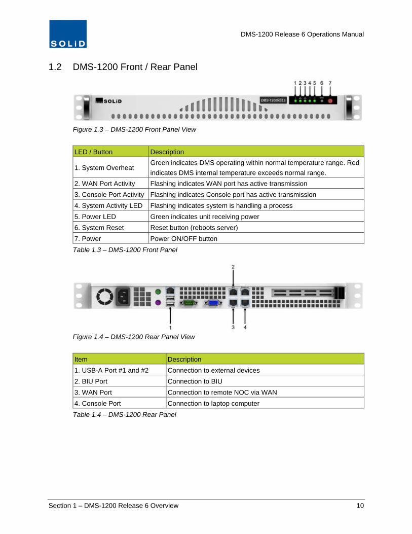
1.2 DMS-1200 Front / Rear Panel
Figure 1.3 – DMS-1200 Front Panel View
LED / Button Description
1. System Overheat Green indicates DMS operating within normal temperature range. Red indicates DMS internal temperature exceeds normal range.
2. WAN Port Activity Flashing indicates WAN port has active transmission 3. Console Port Activity Flashing indicates Console port has active transmission 4. System Activity LED Flashing indicates system is handling a process 5. Power LED Green indicates unit receiving power 6. System Reset Reset button (reboots server) 7. Power Power ON/OFF button Table 1.3 – DMS-1200 Front Panel
Figure 1.4 – DMS-1200 Rear Panel View
Item Description 1. USB-A Port #1 and #2 Connection to external devices 2. BIU Port Connection to BIU 3. WAN Port Connection to remote NOC via WAN 4. Console Port Connection to laptop computer Table 1.4 – DMS-1200 Rear Panel
DMS-1200 Release 6 Operations Manual
Section 1 – DMS-1200 Release 6 Overview 11
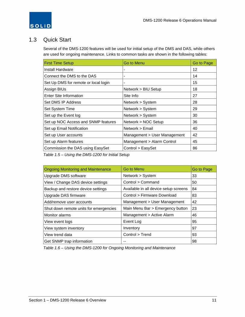
1.3 Quick Start Several of the DMS-1200 features will be used for initial setup of the DMS and DAS, while others are used for ongoing maintenance. Links to common tasks are shown in the following tables:
First Time Setup Go to Menu Go to Page Install Hardware - 12 Connect the DMS to the DAS - 14 Set Up DMS for remote or local login - 15 Assign BIUs Network > BIU Setup 18 Enter Site Information Site Info 27 Set DMS IP Address Network > System 28 Set System Time Network > System 29 Set up the Event log Network > System 30 Set up NOC Access and SNMP features Network > NOC Setup 36 Set up Email Notification Network > Email 40 Set up User accounts Management > User Management 42 Set up Alarm features Management > Alarm Control 45 Commission the DAS using EasySet Control > EasySet 86 Table 1.5 – Using the DMS-1200 for Initial Setup
Ongoing Monitoring and Maintenance Go to Menu Go to Page Upgrade DMS software Network > System 33 View / Change DAS device settings Control > Command 50 Backup and restore device settings Available in all device setup screens 84 Upgrade DAS firmware Control > Firmware Download 83 Add/remove user accounts Management > User Management 42 Shut down remote units for emergencies Main Menu Bar > Emergency button 23 Monitor alarms Management > Active Alarm 46 View event logs Event Log 95 View system inventory Inventory 97 View trend data Control > Trend 93 Get SNMP trap information -- 98 Table 1.6 – Using the DMS-1200 for Ongoing Monitoring and Maintenance

DMS-1200 Release 6 Operations Manual
Section 2 – Hardware Installation 12
2 Hardware Installation If the DMS server has already been installed as part of the DAS installation, skip to the next section for Log In and BIU Assignment instructions.
The DAS management system server (DMS-1200) is typically mounted in the head end rack above the ODUs and in close proximity to the BIUs. The server has an internal power supply and requires standard 120-240V AC power. A power cable ships with the unit.
The DMS-1200 server requires 1U in a standard 19-inch equipment rack but should have 1U above and below for air circulation.
SOLiD technicians configure and label the ALLIANCE DAS equipment prior to shipment. When unpacking the equipment, note all labeling and inspect the hardware. Contact SOLiD Support if the product is damaged.
In This Section Required Materials
Installing the DMS Hardware
Connecting the DMS-1200 to the DAS
Connecting Multiple BIUs to the DMS-1200
Connecting to the DMS-1200

DMS-1200 Release 6 Operations Manual
Section 2 – Hardware Installation 13
2.1 Required Materials Before you begin, make sure you have the following items. Those items marked with an “O” ship with the unit. Items marked with an “X” are not included. Tools are not included.
Installation Step Accessory Status DMS-1200 rack mounting M6 Screws (Qty 4) X Rack mount brackets O WAN port connection (for making remote connection)
Straight type CAT5 Ethernet cable (Qty 1) X
BIU port connection Straight type 2m CAT5 Ethernet cable (Qty 1) O Connection to power supply AC 110-220V Power Cable (Qty 1) O Table 2.1 – Tools and Accessories for Installing DMS Equipment
2.2 Installing the DMS Hardware
1. Using the rack mount brackets, install the DMS-1200 in the rack, making sure to leave 1U of space above and below the DMS and other DAS components. This gap provides air circulation to help dissipate heat from the equipment.
2. Insert M6 screws in the mounting holes and tighten the screws to secure the unit.
3. Connect the server to a power source (typically a wall socket) using the supplied power cable; then power on the server.

DMS-1200 Release 6 Operations Manual
Section 2 – Hardware Installation 14
2.3 Connecting the DMS-1200 to the DAS 1. Plug one end of the CAT5e Ethernet cable into the BIU port at the back of the DMS.
2. Connect the other end into the Ethernet Port located on the front of the Main Central Processor Unit (MCPU) at the front of the BIU.
The DMS will automatically assign an IP address to the BIU.
Figure 2.1 – DMS-1200 to BIU Connection

DMS-1200 Release 6 Operations Manual
Section 2 – Hardware Installation 15
2.4 Connecting Multiple BIUs to the DMS-1200 For configurations with multiple BIUs, use a Gigabit Ethernet switch. The Gigabit Ethernet switch should be used exclusively for this purpose and no other devices besides the DMS and BIUs should be connected to it.
1. Plug a CAT5e Ethernet cable into the Ethernet Port located on the Main Central Processor Unit (MCPU) at the front of each BIU. Plug the other end into the switch.
2. Connect the switch to the BIU port at the back of the DMS.
The DMS will automatically assign an IP address to each BIU.
TIP: SOLiD recommends using a Gigabit Ethernet switch from manufacturers like NETGEAR – model NETGEAR JGS524 24-port GB Ethernet Switch – or equivalent.
2.5 Connecting to the DMS-1200
You can set up the DMS-1200 for either local (onsite) or remote login.
1. Local setup: To connect your laptop directly to the DMS-1200 while onsite, connect one end of an Ethernet cable into the Ethernet port on your laptop. Connect the other end to the Console port on the back of the DMS.
TIP: If working onsite, turn off the PC’s WiFi feature. The PC should not be connected to the public Internet while it’s also connected to the Console port on the DMS. Make sure your PC has an available Ethernet port and Automatic DHCP is enabled in your PC’s network settings.
2. Remote setup: To setup the DMS-1200 for remote login from an external NOC, connect one
end of an Ethernet cable into the WAN port on the back of the DMS-1200. Connect the other end to your data network.
Figure 2.2 – WAN Port Connection for Remote Login

DMS-1200 Release 6 Operations Manual
Section 3 – Login and BIU Assignment 16
3 Login and BIU Assignment You can log in to the DMS-1200 either while onsite or from an offsite location like a Network Operations Center (NOC).
Before you can use the DMS-1200 to manage the DAS, you will need to register or “assign” each BIU in the system. This is a one-time setup process and is not required each time you log in to the BIU. This section provides instructions on how to assign BIUs and how to use the DMS-1200 menus and navigation features.
In This Section Logging in
Assigning BIUs
Viewing Remote Access Settings
Using the Main Screen
System Status
System Topology View
Navigation Bar Menus

DMS-1200 Release 6 Operations Manual
Section 3 – Login and BIU Assignment 17
3.1 Logging in 1. Log in to the DMS using one of two methods:
a. If you are working onsite and your laptop is connected to the DMS Console port: open your web browser and enter http://solid.local or the default IP address: 192.168.58.1
TIP: To set up a secure session (SSL), use https:// before the URL or IP address.
b. If logging in remotely: open your web browser and enter the DMS-1200’s Outside IP Address.
(See the section Setting the DMS IP Address on page 28.)
2. At the Login Window, enter the User ID and Password. The default Administrator account uses the ID/password admin/admin. Click Login or press the Enter key.
The default Admin account is already set up. You can add, edit and delete accounts, except for the Admin account. SOLiD recommends changing the Admin password from the default (see the Adding / Deleting User Accounts section on page 43).

DMS-1200 Release 6 Operations Manual
Section 3 – Login and BIU Assignment 18
3.2 Assigning BIUs When you connect the DMS to the DAS, the DMS should automatically recognize the system’s BIUs and load BIU information to the Unassigned BIU list. From there, you will need to add the system’s BIUs to the Assigned BIU list before you can manage them using the DMS.
If a connected BIU is not automatically recognized by the DMS, you can manually add it to the Assigned BIU list.
1. On the Network menu, click BIU Setup.
2. Click the Setup tab. Assign BIUs according to these guidelines:
a. If the BIU appears on the Unassigned BIU list, check Use and then click Apply to move it to the Assigned list.
TIP: The DHCP IP displayed is the IP automatically assigned to an unassigned BIU. When you click Apply, a Static IP is assigned so that all BIUs will be arranged in numerical order.

DMS-1200 Release 6 Operations Manual
Section 3 – Login and BIU Assignment 19
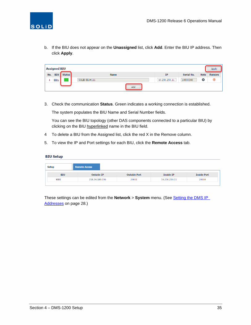
b. If the BIU does not appear on the list, click Add. Enter the BIU IP address, then click Apply.
3. Check the communication Status. Green indicates a working connection is established.
The system populates the BIU Name and Serial Number fields.
3.2.1 Viewing Remote Access Settings
For Assigned BIUs, you can view the current Outside and Inside IP settings from the Remote Access tab. To change the IP settings, go to the Network > System menu.
(See Setting the DMS IP Addresses on page 28.)

DMS-1200 Release 6 Operations Manual
Section 3 – Login and BIU Assignment 20
3.3 Using the Main Screen The Main screen shows the current status of the DMS and provides access to the Navigation Bar menus and submenus.
3.3.1 System Status
You can view the current DAS status, topology, alarm conditions and DMS connection status from the options at the top of the Navigation Bar.
You can also shut down remote units in the system in case of emergencies. (This feature is only available to Administrators.)
Option Action / Status
Topology Click on the icon to show system hierarchy in graphical form.
Active Alarm Click to display a summary of current active alarms.
Emergency Click to shut off remote units in case of Emergency.
Name, login, time Displays the name of the current user and login time.
Logout Click to quit the program.
Date/Time Displays current date and time.
DMS Status
Green = normal operation with no fault conditions. Yellow = a user is currently logged into the ALLIANCE DAS using the MC-DAS management software (GUI). Red = the DMS is not connected to the ALLIANCE DAS.
Table 3.1 – Status Options
You can also see a list of current system events by clicking on the Event bar at the bottom of the screen.
DMS-1200 Release 6 Operations Manual
Section 3 – Login and BIU Assignment 21
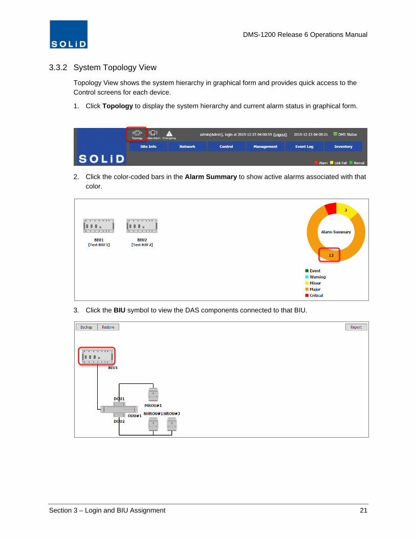
3.3.2 System Topology View
Topology View shows the system hierarchy in graphical form and provides quick access to the Control screens for each device.
1. Click Topology to display the system hierarchy and current alarm status in graphical form.
2. Click the color-coded bars in the Alarm Summary to show active alarms associated with that color.
3. Click the BIU symbol to view the DAS components connected to that BIU.

DMS-1200 Release 6 Operations Manual
Section 3 – Login and BIU Assignment 22
4. Use the other features on the Topology screen according to these guidelines:
The Backup feature creates an internal backup file of all operating settings for the BIU and the DAS components connected to that BIU.
(For more information on the Backup and Restore features, see the section Backing up and Restoring Device Settings on page 84. You can also schedule automatic backups. See Scheduling the System Backup on page 32.)
Use the Restore feature to reapply the settings from the backup files.
Use the Report feature to download a spreadsheet showing current operational settings.
5. From the Topology screen, click on any device to view its Control screen where you can
monitor or change settings for that device.
(See the DAS Device Control section starting on page 42 for instructions for using the Control screens to configure DAS devices.)
Figure 3.1 – Device Control Screen for MROU

DMS-1200 Release 6 Operations Manual
Section 3 – Login and BIU Assignment 23
3.3.3 Emergency Shut-off Function
The Administrator can turn off all amplifiers in the remote units by clicking the Emergency button in the DMS-1200 main screen. For systems with multiple BIUs, the Administrator can turn off remotes on a per BIU basis.
NOTE: This feature is only available to Administrators.
To turn off remotes
1. Click on the Emergency icon at the top of the screen.
2. Click on an individual BIU to shut off remotes just connected to that BIU or select SHUTOFF ALL to turn off amplifiers in all remotes in the DAS.
Figure 3.2 – Emergency Shut-off Function
3. For security, the system will prompt for the Adminstrator password. Enter the password and click OK.
The progress bar shows status.
DMS-1200 Release 6 Operations Manual
Section 3 – Login and BIU Assignment 24
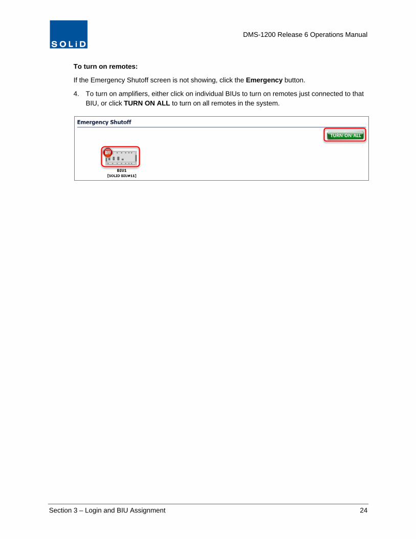
To turn on remotes:
If the Emergency Shutoff screen is not showing, click the Emergency button.
4. To turn on amplifiers, either click on individual BIUs to turn on remotes just connected to that BIU, or click TURN ON ALL to turn on all remotes in the system.

DMS-1200 Release 6 Operations Manual
Section 3 – Login and BIU Assignment 25
3.3.4 Navigation Bar Menus
The menus on the Navigation Bar are used to set up and manage the DMS and DAS components.
Navigation Bar Sub Menu Action / Status
Site Info -- Manage DAS site information (location, installation contractor, technical support contact).
Network
System
Manage network IP addresses, NOC locations. Edit DMS time zone and support information. Clear Event logs. Schedule backups. Upgrade DMS software. Reboot DMS.
BIU Setup Setup system BIUs and Remote Access. NOC Setup Manage SNMP agent settings.
Email Add, delete or edit contact information for administrators / technicians to receive Alert notifications via email.
Control
Command Set operating parameters for all DAS components.
EasySet Auto setup. System commissioning DAS components. Power distribution for MDBU band.
Firmware Download Manage firmware updates for DAS components.
Trend View operating data (e.g. power levels, temp) for DAS components in graphical format.
Management Active Alarm
View current log of alarm events and troubleshooting tips.
Alarm Control Define alarms for all DAS components. User Management Add, delete or edit DMS user accounts.
Event Log -- View/print/download event logs which track status changes of ALLIANCE DAS devices.
Inventory -- View/print/download inventory of all DAS components.
Table 3.2 – Navigation Bar Menu and Sub Menus

DMS-1200 Release 6 Operations Manual
Section 4 – DMS-1200 Setup 26
4 DMS-1200 Setup This section provides instructions on using the Site Info and Network menus to set up the DMS-1200 and network interfaces.
In This Section Editing Site Info
Setting the DMS IP Addresses
Setting System Time
Managing the Event Log
Managing the Trend Log
Scheduling the System Backup
Upgrading DMS Software
Rebooting the DMS Server
Assigning / Removing BIUs
Managing NOC and SNMP Settings
Setting up Email Notification
Managing Email Server Settings

DMS-1200 Release 6 Operations Manual
Section 4 – DMS-1200 Setup 27
4.1 Editing Site Info 1. On the Navigation Bar, click Site Info.
2. Edit Site Info details according to the following guidelines:
Option Action
Site Name / Site Address Specify the location of the DAS site.
DMS Version DMS software version is auto-populated by the system.
Latitude / Longitude Enter the geographic coordinates of the site.
Picture Upload a picture of the site in JPEG format.
Installation Contractor Provide contact information for the installation contractor.
Contacts / Information Provide contact details for support and technical personnel. Add any additional information relevant to the DAS site.
Table 4.1 – Site Info Settings
3. Click Apply when you are done. Changes are applied immediately.
Picture

DMS-1200 Release 6 Operations Manual
Section 4 – DMS-1200 Setup 28
4.2 Setting the DMS IP Addresses Configure IP Address information for both Outside (remote) and Inside (onsite) access from the Network > System menu.
1. On the Network menu, click System.
2. Edit the Network settings according to the following guidelines:
Option Action
Outside IP Address Enter the external IP address for the DMS-1200. This is the IP address for the WAN port at the back of DMS-1200.
Outside Subnet Mask Enter the Outside Subnet Mask address.
Outside Gateway Enter the Outside Gateway address.
Inside IP Address Enter the internal IP address of the DMS-1200 server. This is the IP address for the BIU port at the back of DMS-1200.
Inside Subnet Mask Enter the Inside Subnet Mask.
Table 4.2 – Network Settings
3. Click Apply to save the settings. Changes are applied immediately.

DMS-1200 Release 6 Operations Manual
Section 4 – DMS-1200 Setup 29
4.3 Setting System Time You can manually set the system time or use a Network Time Protocol (NTP) service.
1. On the Network menu, click System.
2. Edit the Time settings according to the following guidelines:
Option Action / Status
Time Zone Enter the local time zone for the DMS.
NTP Enable Turn On if you are using a Network Time Protocol (NTP) service to acquire the date/time. Otherwise, turn Off to set time manually.
NTP Server If you are using an NTP service, enter the IP address or DNS name of the NTP server. Leave this blank if you are using the NIST Internet Time Server at nist1.symmetricom.com, which is the system default.
Set Date and Time If you are not using a Network Time Protocol (NTP) service to acquire the date/time (NTP Enable is set to Off), then enter the current date and local time here. Click Set when you are done.
Table 4.3 – Time Settings
3. Click Apply to save the settings. Changes are applied immediately.
DMS-1200 Release 6 Operations Manual
Section 4 – DMS-1200 Setup 30
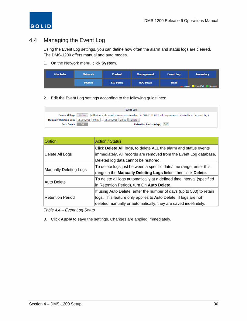
4.4 Managing the Event Log Using the Event Log settings, you can define how often the alarm and status logs are cleared. The DMS-1200 offers manual and auto modes.
1. On the Network menu, click System.
2. Edit the Event Log settings according to the following guidelines:
Option Action / Status
Delete All Logs Click Delete All logs, to delete ALL the alarm and status events immediately. All records are removed from the Event Log database. Deleted log data cannot be restored.
Manually Deleting Logs To delete logs just between a specific date/time range, enter this range in the Manually Deleting Logs fields, then click Delete.
Auto Delete To delete all logs automatically at a defined time interval (specified in Retention Period), turn On Auto Delete.
Retention Period If using Auto Delete, enter the number of days (up to 500) to retain logs. This feature only applies to Auto Delete. If logs are not deleted manually or automatically, they are saved indefinitely.
Table 4.4 – Event Log Setup
3. Click Apply to save the settings. Changes are applied immediately.

DMS-1200 Release 6 Operations Manual
Section 4 – DMS-1200 Setup 31
4.5 Managing the Trend Log Use the Trend Log settings to manually delete all trend log data or setup an auto deletion routine.
1. On the Network menu, click System.
2. Edit the Trend Log settings according to the following guidelines:
Option Action / Status
Delete All Logs Click Delete All logs, to delete ALL trend data. All records are removed from the Trend Log database. Deleted log data cannot be restored.
Auto Delete To delete all logs automatically at a defined time interval (specified in Retention Period), turn On Auto Delete.
Retention Period Enter the number of days to retain logs. Maximum value for this field is 500 days.
Table 4.5 – Trend Log Setup
3. Click Apply to save the settings. Values are saved immediately.

DMS-1200 Release 6 Operations Manual
Section 4 – DMS-1200 Setup 32
4.6 Scheduling the System Backup Use the Scheduling Backup settings to turn on/off auto backup and set schedule and retention times.
1. On the Network menu, click System.
2. Edit the Scheduling Backup settings according to the following guidelines:
Option Action / Status
Enable To activate/deactivate an automatic backup routine, click Enable on/off.
Schedule Choose the frequency and time of day for the auto backup.
Retention Limit Set the maximum number of backups to retain per BIU.
Table 4.6 –Scheduling Backups
3. Click Apply to save the settings. Values are saved immediately.

DMS-1200 Release 6 Operations Manual
Section 4 – DMS-1200 Setup 33
4.7 Upgrading DMS Software Periodic software upgrades are available for the DMS-1200 server. Contact SOLiD Support for details. (You can also upgrade firmware for the DAS components using the DMS-1200. See the section Upgrading Firmware for DAS Components starting on page 83.)
1. Obtain the latest DMS software from SOLiD Support. Load software on the management PC.
2. On the Network menu, click System.
3. Click Choose File. From your PC’s file directory, select the DMS software file.
4. Click Upgrade. The DMS will go offline while new software is applied.
5. After upgrading the DMS software, reboot the DMS using the instructions below.
6. In the Site Info screen, check the DMS Version number to make sure it matches the software you have just loaded.

DMS-1200 Release 6 Operations Manual
Section 4 – DMS-1200 Setup 34
4.8 Rebooting the DMS Server
After upgrading the DMS software or if any of the DMS functions become unresponsive, reboot the DMS from the System menu.
1. On the Network menu, click System.
2. Click Reboot. It may take up to one minute for the system to come back online.
TIP: You can also press the Reset button on the front panel of the DMS server to reboot the system.
4.9 Assigning / Removing BIUs When you connect the DMS-1200 to the DAS, the DMS should automatically recognize the system’s BIUs and load BIU information to the Unassigned BIU list. You will need to move unassigned BIUs to the Assigned BIU list before you can manage the BIU using the DMS-1200.
If a connected BIU is not automatically recognized by the DMS, you can also manually add it to the Assigned BIU list.
1. On the Network menu, click BIU Setup.
2. Click the Setup tab. Assign the BIU according to these guidelines:
a. If the BIU appears on the Unassigned BIU list, check Use and then click Apply to move it to the Assigned list.
NOTE: The DHCP IP displayed is the IP automatically assigned to an unassigned BIU. When you click Apply, a Static IP is assigned so that all BIUs will be arranged in numerical order.
DMS-1200 Release 6 Operations Manual
Section 4 – DMS-1200 Setup 35
b. If the BIU does not appear on the Unassigned list, click Add. Enter the BIU IP address. Then click Apply.
3. Check the communication Status. Green indicates a working connection is established.
The system populates the BIU Name and Serial Number fields.
You can see the BIU topology (other DAS components connected to a particular BIU) by clicking on the BIU hyperlinked name in the BIU field.
4 To delete a BIU from the Assigned list, click the red X in the Remove column.
5. To view the IP and Port settings for each BIU, click the Remote Access tab.
These settings can be edited from the Network > System menu. (See Setting the DMS IP Addresses on page 28.)
DMS-1200 Release 6 Operations Manual
Section 4 – DMS-1200 Setup 36
4.10 Managing NOC and SNMP Settings The NOC Setup menu allows you to manage the SNMP interface between the DMS-1200 and the Network Operation Center (NOC).
4.10.1 Set the SNMP Heartbeat
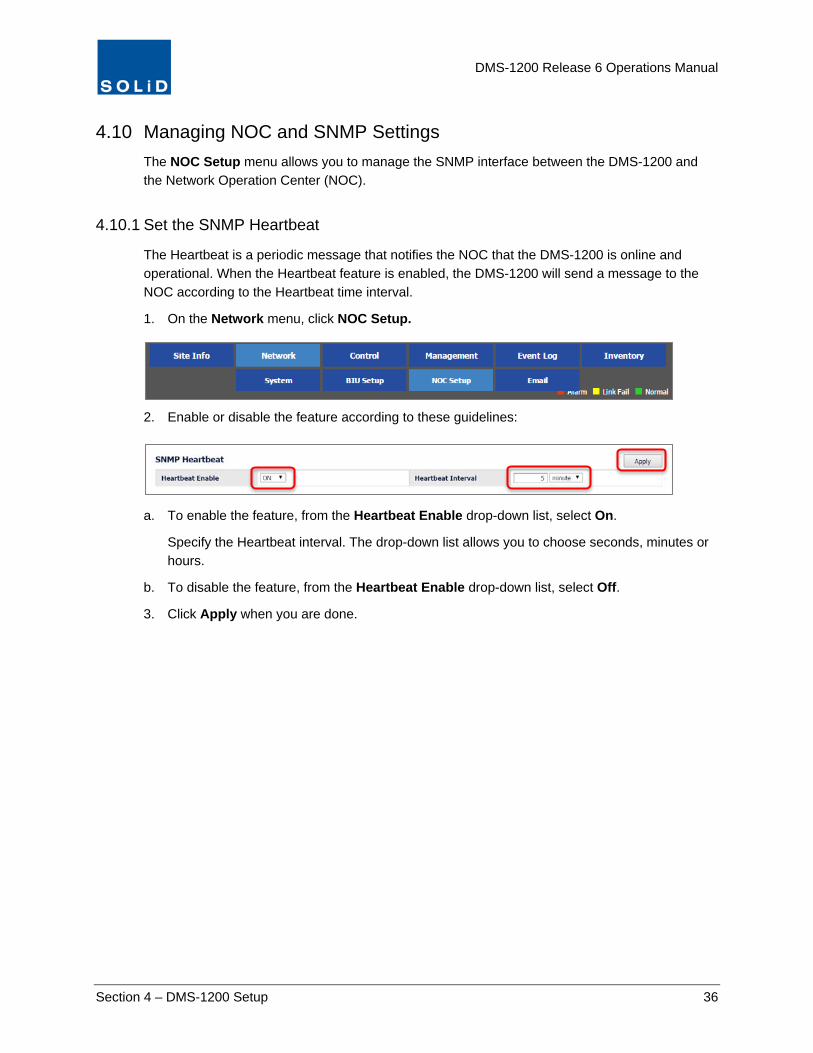
The Heartbeat is a periodic message that notifies the NOC that the DMS-1200 is online and operational. When the Heartbeat feature is enabled, the DMS-1200 will send a message to the NOC according to the Heartbeat time interval.
1. On the Network menu, click NOC Setup.
2. Enable or disable the feature according to these guidelines:
a. To enable the feature, from the Heartbeat Enable drop-down list, select On.
Specify the Heartbeat interval. The drop-down list allows you to choose seconds, minutes or hours.
b. To disable the feature, from the Heartbeat Enable drop-down list, select Off.
3. Click Apply when you are done.
DMS-1200 Release 6 Operations Manual
Section 4 – DMS-1200 Setup 37
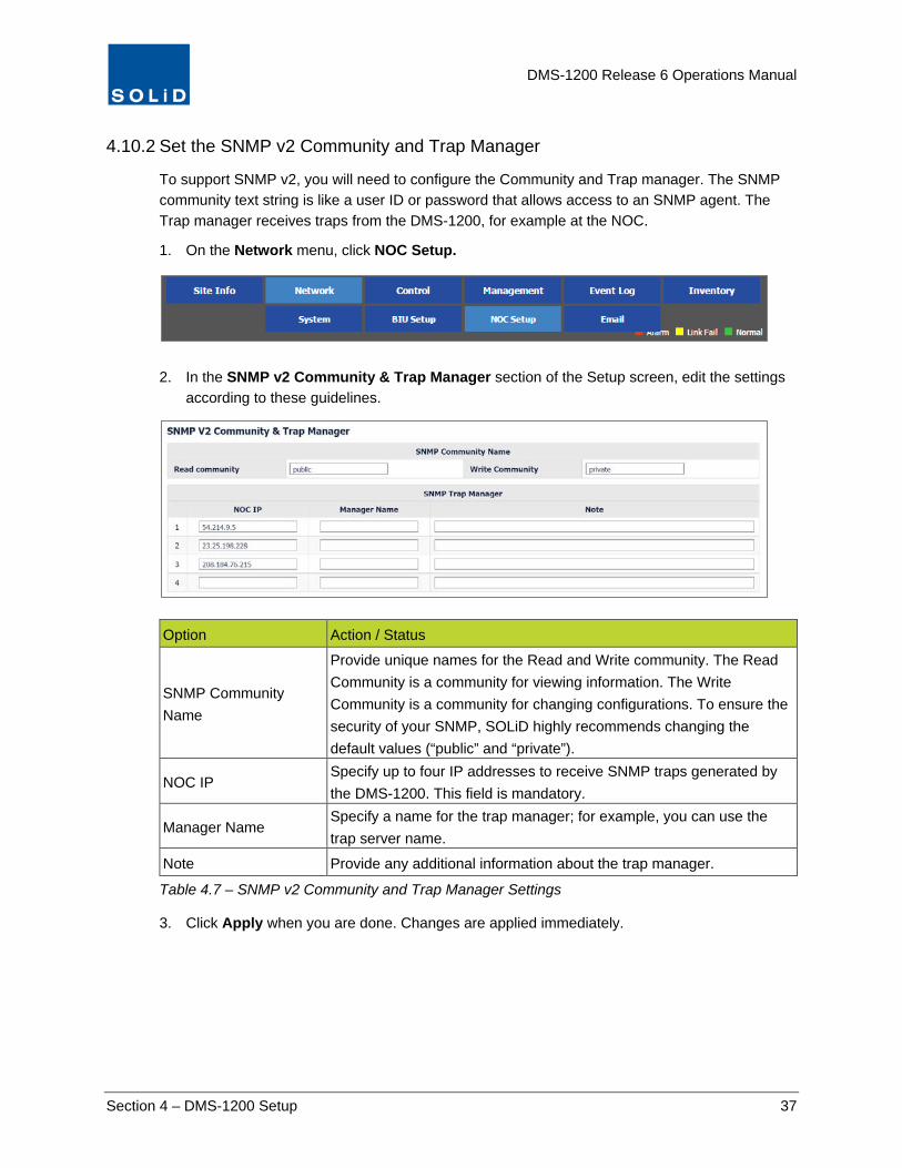
4.10.2 Set the SNMP v2 Community and Trap Manager
To support SNMP v2, you will need to configure the Community and Trap manager. The SNMP community text string is like a user ID or password that allows access to an SNMP agent. The Trap manager receives traps from the DMS-1200, for example at the NOC.
1. On the Network menu, click NOC Setup.
2. In the SNMP v2 Community & Trap Manager section of the Setup screen, edit the settings
according to these guidelines.
Option Action / Status
SNMP Community Name
Provide unique names for the Read and Write community. The Read Community is a community for viewing information. The Write Community is a community for changing configurations. To ensure the security of your SNMP, SOLiD highly recommends changing the default values (“public” and “private”).
NOC IP Specify up to four IP addresses to receive SNMP traps generated by the DMS-1200. This field is mandatory.
Manager Name Specify a name for the trap manager; for example, you can use the trap server name.
Note Provide any additional information about the trap manager.
Table 4.7 – SNMP v2 Community and Trap Manager Settings
3. Click Apply when you are done. Changes are applied immediately.

DMS-1200 Release 6 Operations Manual
Section 4 – DMS-1200 Setup 38
4.10.3 Set the SNMP v3 User and Trap Session
SNMP v3 provides secure access to devices by authenticating and encrypting packets over the network. To support SNMP v3, first configure user and trap session information.
1. On the Network menu, click NOC Setup.
2. In the SNMP v3 User & Trap Session section of the Setup screen, edit the settings
according to these guidelines.
Option Action / Status
Type Define access authority: Read-only or Read-write. This field is mandatory.
User Enter a User name. This field is mandatory.
Security Enter Security Level: None = no authentication required. No Privacy = authentication. Privacy = Authentication + encryption.
Authentication Protocol If security level is No Privacy or Privacy, select the authentication protocol and enter password. The minimum password length is eight characters.
Privacy Protocol If security level is Privacy, select the privacy protocol and enter password. The minimum password length is eight characters.
Table 4.8 – SNMP v3 User Settings
DMS-1200 Release 6 Operations Manual
Section 4 – DMS-1200 Setup 39
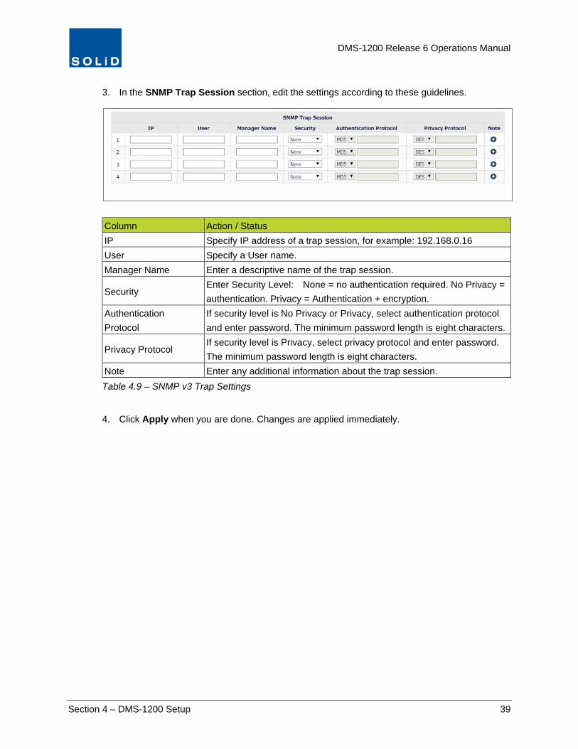
3. In the SNMP Trap Session section, edit the settings according to these guidelines.
Column Action / Status IP Specify IP address of a trap session, for example: 192.168.0.16 User Specify a User name. Manager Name Enter a descriptive name of the trap session.
Security Enter Security Level: None = no authentication required. No Privacy = authentication. Privacy = Authentication + encryption.
Authentication Protocol
If security level is No Privacy or Privacy, select authentication protocol and enter password. The minimum password length is eight characters.
Privacy Protocol If security level is Privacy, select privacy protocol and enter password. The minimum password length is eight characters.
Note Enter any additional information about the trap session. Table 4.9 – SNMP v3 Trap Settings
4. Click Apply when you are done. Changes are applied immediately.

DMS-1200 Release 6 Operations Manual
Section 4 – DMS-1200 Setup 40
4.11 Setting up Email Notification The DMS-1200 can send emails to administrators or technicians to notify them of alarm conditions. You can customize the email notifications to report alarms according to the severity level. For example, some administrators may only want to be notified of “critical” alarms, while others may want to see all alarms reported by the system.
TIP: The list of email contacts is distinct from the list of DMS users. Entry on one list does not automatically populate the other list.
1. On the Network menu, click Email.
2. Click the Contact tab. To add a contact, click Add.
3. Edit the Email Notification settings according to the following guidelines:
Option Action / Status
Name / Email Enter the contact’s name and email address.
Rules Level
From the drop-down list, choose the Alert Level. All Alarm events at that level and above (more severe) will generate an email notification. Check Exact Match to generate notification for just that level. Alarm Levels are defined in the Management > Alarm Control menu.
Note Enter any relevant information about the contact.
Table 4.10 – Email Contact Setup
4. Click Apply when you are done.
5. To delete a contact, click Remove next to the user’s name.

DMS-1200 Release 6 Operations Manual
Section 4 – DMS-1200 Setup 41
4.12 Managing Email Server Settings For the DMS-1200 to send emails, you must first define settings for the email server on your network.
1. On the Network menu, click Email.
2. Click the SMTP Server tab.
3. Complete the information for the SMTP server according to these guidelines:
Column Action / Status SMTP Server Enter IP address or DNS address of the server used for sending email.
Port
Enter the email server TCP port. Common SMTP ports include: Port 25 = non-encrypted server using SMTP authentication. Port 465 = secure SSL/TLS encryption server. SSL/TLS encryption is started automatically before any SMTP level communication. Port 587 = secure (TLS) using STARTTLS authentication. SSL/TLS encryption may be started by STARTTLS command at SMTP level if server supports it.
User Name / Password
Enter a user name and password to receive email notifications.
From Name / Email Enter sender name / email address to be displayed on / notification email. Secure Connection Enter any security protocol used on the email server.
Notification Period Specify period to collect and transmit alarms generated: 2-60 minutes. Table 4.11 – Email Server Setup
4. Click Apply when you are done. Changes are saved immediately.
5. To test the email feature, click Test. Enter a name and email address to receive the test notification, then click Send.

DMS-1200 Release 6 Operations Manual
Section 5 – User Account Setup 42
5 User Account Setup From the Management > User Management menu, you can see who is currently logged in to the DMS and manage who has access to the system.
NOTE: Only Administrators can add or delete user accounts.
Users can be assigned to one of four user types, each with different access permissions:
User Type Definition
Admin Full access. Can view and change all equipment and user settings.
Tech Can view and change all equipment level settings, but view-only permissions for user management.
User
Can view and change most equipment level settings and can download and apply firmware updates: Restrictions include: No access to Management menu options No access to Network > System menu options View-only EasySet settings.
Client View-only permissions
Table 5.1 – User Types
In This Section Adding / Deleting User Accounts
Viewing Active Users
Related Topics Email Notification: The DMS-1200 can send emails to system users (like administrators or technicians) to notify them of alarm conditions. (See the Setting up Email Notification section.)

DMS-1200 Release 6 Operations Manual
Section 5 – User Account Setup 43
5.1 Adding / Deleting User Accounts Only Administrators can add or delete user accounts.
1. On the Management menu, click User Management.
2. Click the User tab to see a list of all registered users of the DMS-1200.
3. To add a user, click Add.
4. In the Add User dialog box, enter the user information. Fields with an asterisk (*) are
required.
Column Action / Status ID / Name Enter the user login ID and name.
Group
Assign the user to a group: Admin: View/Change All Equipment and User Management Settings. Tech: View/Change Equipment Level Settings. View-only User Management. User: View/Change Equipment Level Settings. Exceptions: No access to Management menu options. No access to Network > System menu options. View-only EasySet settings. Firmware download permitted. Client: View only permissions.
Department / Note Enter the department and any additional information about the user.
Password Enter a password. Passwords must be at least four characters. Numbers and special characters are permitted.
Office / Cell Enter contact telephone numbers.
Table 5.2 – DMS User Setup
DMS-1200 Release 6 Operations Manual
Section 5 – User Account Setup 44
5. Click Apply when you are done adding user information.
6. To edit information for a user, like changing the password, click the Edit icon.
7. To delete a user, click Remove next to the user name. This action cannot be undone.
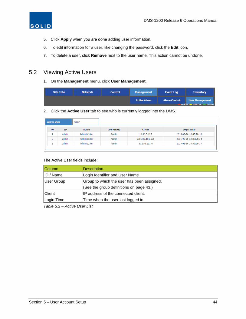
5.2 Viewing Active Users 1. On the Management menu, click User Management.
2. Click the Active User tab to see who is currently logged into the DMS.
The Active User fields include:
Column Description ID / Name Login Identifier and User Name User Group Group to which the user has been assigned.
(See the group definitions on page 43.) Client IP address of the connected client. Login Time Time when the user last logged in. Table 5.3 – Active User List

DMS-1200 Release 6 Operations Manual
Section 6 – System Alarm Setup 45
6 System Alarm Setup Error conditions that produce Alarms for system components – like the BIU, MDBU, DOU, etc. – are pre-defined at the SOLiD factory. The Alarm menus allow you to view active alarms for these components, customize how they are reported, and see troubleshooting tips for resolving them.
In This Section Monitoring Alarms and Viewing Troubleshooting Tips
Customizing Alarms
Related Topics The DMS provides several methods for monitoring alarms, including:
Active Alarm Summary: View a summary of active alarms by clicking Topology or Active Alarm in the Status Bar (see page 20).
Alarm Event Log: View all Alarms – active and resolved – from the Event Log (see page 95).
Email Notification: Receive email notification of alarm events (see the Setting up Email Notification page 40).
Suggestions on Alarm Levels and Hysteresis: See the SNMP Trap section for tips on alarm levels and hysteresis.

DMS-1200 Release 6 Operations Manual
Section 6 – System Alarm Setup 46
6.1 Monitoring Alarms and Viewing Troubleshooting Tips 1. On the Management menu, click Active Alarm.
2. Click Refresh. Using the drop-down lists at the top of the Active Alarm screen, filter the alarm
list using any of the following criteria:
Field Description BIU Shows all alarms associated with that BIU. Device Shows all alarms associated with the device.
Level Filters by Alarms at that level and above (more severe). Exact Match filters alarms by just that level.
Keyword Filters by specified search text. Note that you can also search by any keyword in the Name and Alarm column.
Table 6.1 – Active Alarm Filter Criteria

DMS-1200 Release 6 Operations Manual
Section 6 – System Alarm Setup 47
You can also filter by any Keyword in the Name and Alarm fields: place your cursor over the text in the field. Then click on the text to see the Input Keyword dialog box. Enter a search keyword then click OK to filter by that keyword.
3. To see a list of troubleshooting tips, click the Remedy icon next to the Alarm.

DMS-1200 Release 6 Operations Manual
Section 6 – System Alarm Setup 48
6.2 Customizing Alarms You can assign severity levels to each alarm, customize alarm levels and notifications, and see troubleshooting tips on how to resolve alarm conditions.
1. On the Management menu, click Alarm Control.
2. To customize Alarms for each device, click on the Alarm Control tab.
3. Click on the device – BIU, DOU, OEU, etc. – to see a list of alarms associated with that device. You can customize the Alarms according to these guidelines:
Field Description Level To assign the same severity level (Event, Warning, Minor, Major, Critical) to all
alarms, select the level using the Level drop-down list. To assign a unique severity level to each alarm, leave the triple dash (---) in the Level drop-down list, then assign a severity level to each alarm.
Mask For a masked alarm, the DMS-1200 will not generate an SNMP trap, but it will continue to report the status of this device in its Alarm lists and Event log.
Hysteresis Time interval before Alarm is reported or the status of a device changes. From the first drop down list, choose a time interval. From the second list, choose seconds or minutes. To assign the same interval to all alarms, enter this interval using the drop-down list at the top of the column. Maximum Hysteresis=30 mins.
Description The default description is the Alarm name. You can edit this text as desired. Remedy Click on the Remedy icon to see suggested fixes for the alarm condition. You
can edit this text as desired. Table 6.2 – Active Alarm Screen
4. Click Apply, when you are finished.
DMS-1200 Release 6 Operations Manual
Section 6 – System Alarm Setup 49
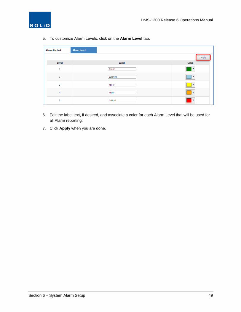
5. To customize Alarm Levels, click on the Alarm Level tab.
6. Edit the label text, if desired, and associate a color for each Alarm Level that will be used for
all Alarm reporting.
7. Click Apply when you are done.

DMS-1200 Release 6 Operations Manual
Section 7 – DAS Device Control 50
7 DAS Device Control The DMS-1200 supports several functions for monitoring and controlling the DAS devices:
• Initial System Commissioning – The initial system commissioning process comes after hardware installation and prepares the DAS to handle live network traffic. Two methods are available: setting parameters individually using the device control screens or using the automated EasySet process. (See the next section System Commissioning with EasySet.)
• Ongoing Device Control and Monitoring – Use the Control screens, explained in this section, at any time to configure existing devices or for new devices added to an operating DAS.
• Firmware Upgrade – Upgrade device firmware as it becomes available. • Trend Data – View and download trend data on device performance. • Inventory Reports – View and download reports on currently installed DAS devices. • Backup and Restore – Save the current DAS configuration for all devices to a backup
file and restore settings as needed.
In This Section Using the Device Control Screens
Setting BIU Parameters
Setting ODU Parameters
Setting OEU Parameters
Setting Remote Optic Unit (ROU) Parameters
LROU Setup
MROU Setup
HROU (TiTAN) Setup
NHROU (THOR) Setup
Green Mode Setup
PIMD Level Measurement (HROU Only)
External Alarm Setup (HROU Only)
Upgrading Firmware for DAS Components
Backing up and Restoring Device Settings

DMS-1200 Release 6 Operations Manual
Section 7 – DAS Device Control 51
7.1 Using the Device Control Screens 1. From the Control menu, click Command.
2. Select the target device from the Tree Menu
or the Menu Bar drop-down lists to load its control screen.
The status for each device is shown in one of three states:
Green = Device is operating normally.
Yellow = Device is not communicating.
Red = Alarm condition has occurred on the device.
DMS-1200 Release 6 Operations Manual
Section 7 – DAS Device Control 52
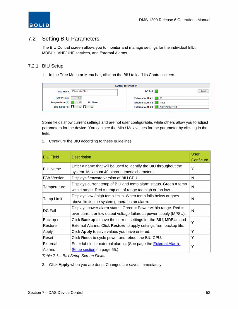
7.2 Setting BIU Parameters The BIU Control screen allows you to monitor and manage settings for the individual BIU, MDBUs, VHF/UHF services, and External Alarms.
7.2.1 BIU Setup
1. In the Tree Menu or Menu bar, click on the BIU to load its Control screen.
Some fields show current settings and are not user configurable, while others allow you to adjust parameters for the device. You can see the Min / Max values for the parameter by clicking in the field.
2. Configure the BIU according to these guidelines:
BIU Field Description User Configure
BIU Name Enter a name that will be used to identify the BIU throughout the system. Maximum 40 alpha-numeric characters.
Y
F/W Version Displays firmware version of BIU CPU. N
Temperature Displays current temp of BIU and temp alarm status. Green = temp within range. Red = temp out of range too high or too low.
N
Temp Limit Displays low / high temp limits. When temp falls below or goes above limits, the system generates an alarm.
N
DC Fail Displays power alarm status. Green = Power within range. Red = over-current or low output voltage failure at power supply (MPSU).
N
Backup / Restore
Click Backup to save the current settings for the BIU, MDBUs and External Alarms. Click Restore to apply settings from backup file.
Y
Apply Click Apply to save values you have entered. Y Reset Click Reset to cycle power and reboot the BIU CPU. Y External Alarms
Enter labels for external alarms. (See page the External Alarm Setup section on page 55.)
Y
Table 7.1 – BIU Setup Screen Fields
3. Click Apply when you are done. Changes are saved immediately.

DMS-1200 Release 6 Operations Manual
Section 7 – DAS Device Control 53
7.2.2 MDBU, VHF / UHF Setup
1. In the Tree Menu or Menu bar, click an MDBU or the VHF+UHF tab to load its Control screen.
Some fields show current settings and are not user configurable, while others allow you to configure parameters for the device.
You can see the Min / Max values for the parameter by clicking in the field.
TIP: SOLiD’s recommended device settings can be found in the document: ALLIANCE DAS Tech Note - Commissioning with DMS-1200 available from SOLiD support.
2. Configure TX and RX settings for the MDBU according to the guidelines in the following
tables:
MDBU Field Description User Configure
F/W Version Displays firmware version of MDBU. N
Temperature Displays current temperature of MDBU. N
Power Distribution
Shows status of Power Distribution feature. (Power Distribution is turned on/off from the Control > EasySet menu.)
N
Reset Click Reset to cycle power and reboot MDBU. Y
Name Enter Band/Carrier for that MDBU port. Max 40 characters. Y
On/Off Click to turn MDBU port On/Off. Active ports should be turned on; inactive off.
Y
2.5 TDD Only
Band Select From drop-down list, select the band to be use: Low Band, Middle Band, or Upper Band. The same band is automatically assigned for the 2.5 RDD amplifiers (RDUs) in the remotes.
Table continues on next page

DMS-1200 Release 6 Operations Manual
Section 7 – DAS Device Control 54
MDBU Field Description User Configure
Tx PLL Lock Tx Phase Locked Loop status. Green = Normal (locked). Red = PLL unlocked. (Not applicable to VHF/UHF setup.)
N
Tx In Power Shows Tx input power on that port (±2dB) and status: Green = within high/low limits. Red = input power below / above limits. (Displays --- when no input signal is detected.)
Y
Power Limit Enter values for low / high power alarm limits.
Tx In ATT Set attenuation level to be applied to input power. Max = 30 dB. Y
Tx In AGC / ALC
Click toggle to turn Auto Gain Control and Auto Level Control On/Off. Input AGC: The system optimizes BIU gain against each BIU input level. Automatically turns off once complete. Input ALC: Input ALC function can be used to limit input power if it exceeds a predetermined level.
Y
Table 7.2 – MDBU Setup Screen Fields – TX Values
MDBU Field Action / Description User Configure
Rx PLL Lock Rx PLL (Phase Locked Loop) status. Green = Normal (locked). Red = PLL unlocked. (Not applicable to VHF/UHF setup.)
N
RX Out Power Shows RX power: Green = Normal. Red = power exceeds limit. Shows Rx out power on that port. Accuracy is ±2dB. (Displays --- when no output signal is detected.)
Y
Power Limit Set the high power limit. Rx Out ATT Set attenuation level applied to Rx gain from the MDBU. Y Rx Out ALC Click the toggle to turn Auto Level Control On/Off.
If on, system limits RX output power to indicated level. Y
Table 7.3 – MDBU Setup Screen Fields – RX Values
3. Click Apply when you are done. Changes are saved immediately.

DMS-1200 Release 6 Operations Manual
Section 7 – DAS Device Control 55
7.2.3 External Alarm Setup (Optional)
Three dry contacts are located at the BIU back panel that can be used to support external alarms for reporting conditions like a module failure, high temperature condition or power failure. These alarms can be connected to the auxiliary input of the Base station or any other dry-contact application.
The alarm level can be configured using the Management > Alarm Control menu.
ALM #1 and ALM#2 are output alarms only. ALM #3 can be configured for output or input. When all ALMs are configured for output, an event indicates active output on the alarm. When an alarm condition exists, the output relay terminal will operate as shown in the table.
External ALM# Conditions (Switch path) 1/ 2/ 3 N.C Normally closed
COM - N.O Normally open
Table 7.4 – External Alarm Relay Setup Screen Fields
External ALM #3 can be used for output or input. An event indicates active output on the External alarm or active input for the BIU Contact Alarm. To use the ALM #3 for input mode, make sure the dipswitch position 1 and 2 on the MCPU are both set ON.
Figure 7.1 – MCPU Dipswitch
c. When input mode is selected, use the N.O and COM terminals as shown below.
ALM In# Condition 3 N.O Input terminal (+)
COM Ground (-) Table 7.5 – External ALM #3 Input Mode Setup

DMS-1200 Release 6 Operations Manual
Section 7 – DAS Device Control 56
To Activate Alarms for Dry Contacts
1. From the MDBU Control screen, click the External Alarm tab.
2. Check the External ALM Enable box if you want to activate contacts #1, #2, and/or #3.
3. For each enabled contact, check the Enable box for each condition you would like reported.
Note: If you use ALM#3 in input mode, the setup screen will change to reflect that.

DMS-1200 Release 6 Operations Manual
Section 7 – DAS Device Control 57
7.3 Setting ODU Parameters The ODU Control screen allows you to monitor and manage settings for the ODU and the Donor Optic Units (DOUs) in the ODU.
7.3.1 ODU / DOU Setup
1. In the Tree Menu or Menu bar, click the ODU you want to configure to load its control screen.
Active ports are lit in blue; inactive are greyed. Some fields show current settings and are not user configurable. Other fields allow you to configure parameters for the device. You can see the Min / Max values for the parameter by clicking in the field.
2. Configure each active port on the DOUs according to these guidelines:
DOU Fields Action / Description User Configure
F/W Version
Firmware version of DOU. N
LD Power Displays laser diode power levels being transmitted to ROU or OEU. Green = normal. Red = Power is below reference power current.
N
Reset Click Reset to cycle power and reboot the DOU optic module. Y Optic Port PD Power Displays photo diode power being received from ROU or OEU. Green
= normal. Red = Received power falls below reference power level. N
Rx ATT Displays attenuation level applied to receive (RX) side of the DOU. N Rx Optic Comp
Click the toggle to turn On/Off the Auto optical loss compensation function. The auto function applies same level of attenuation as the TX Optic ATT of the ROU or OEU.
Y
Result Shows result after compensating for optical loss: Success: optical compensation has been successful. Over Optic Loss: optical loss generated exceeds limits: 6dBo or more for 4-port DOU (OM4); 11dBo or more for 1-port DOU (OM1). Fail: Communication between the DOU and ROU has failed.
N
Table 7.6 – ODU / DOU Setup Screen
3. Click Apply when you are done. Changes are saved immediately.

DMS-1200 Release 6 Operations Manual
Section 7 – DAS Device Control 58
7.4 Setting OEU Parameters The Optical Expansion Unit (OEU) has two types of optical modules: E-Optic module for connecting the OEU to the ODU, and up to two DOUs for connecting to ROUs. The DOUs used in the OEU are the same units used in the ODU and have the same configuration options.
The OEU Control screen allows you to monitor and manage settings for the OEU, the E-Optic and DOUs.
7.4.1 OEU / DOU Setup
1. In the Tree Menu or Menu bar, click on the OEU you want to configure to load its Control screen.
Some fields show current settings and are not user configurable. Other fields allow you to configure parameters for the device. You can see the Min / Max values for the parameter by clicking in the field.
2. Configure the OEU according to these guidelines:
OEU Field Action / Description User
Configure OEU Name Enter a name that will be used to identify the OEU throughout the
system. Maximum 40 alpha-numeric characters. Y
F/W Version Displays firmware version of the CPU in the OEU. N Temperature Displays current temp of OEU. Also shows temp alarm status.
Green = temp within limits. Red = temp above/below limits. N
Temp Low / High
Shows Low / High temp alarm settings. N
DC Alarm Shows status of DC Power. Green = normal. Red = over-current or low output voltage failure at power supply. Click Reset to restart the power supply unit.
Y (Reset)
Link Fail Status of BIU communication. Green = normal. Red = link failure. N Backup / Restore
Backup saves the current settings for the OEU, E-Optic module, and DOUs. Restore re-applies settings from backup file.
Y
Table 7.7 – OEU System Information Setup Screen Fields

DMS-1200 Release 6 Operations Manual
Section 7 – DAS Device Control 59
E-Optic Field Action / Description User
Configure LD Power Displays current laser diode power of E-Optic module. Green =
normal. Red = power is below reference power current. N
PD Power Displays current photo diode power received from ROU or OEU. Green = normal. Red = power falls below reference power level.
N
Tx Optic Comp
Click the toggle to turn On/Off the Auto optical loss compensation function. Turn on for all active optical ports.
Y
Tx Optic ATT Indicates attenuation for the (RX) receive side of the DOU. Basic ATT value is 10dB for OM4 modules or 24dB for OM1 modules.
N
Optic Result Shows result after compensating for optical loss: Success: optical compensation has been successful. Over Optic Loss: optical loss generated exceeds limits: 6dBo or more for 4-port DOU (OM4); 11dBo or more for 1-port DOU (OM1). Fail: Communication between the DOU and ROU has failed.
N
Run Time Date / Time when optical compensation was last performed. N Run Mode Optical compensation mode:
Auto: Optical compensation was executed by the CPU automatically. Manual: Optical compensation was executed manually by the user.
N
Optic Loss Displays optical loss. Green = optical loss is within tolerance. Red = optical loss exceeds limits: 9dB for OM1; 4dB for OM4.
N
Table 7.8 – E-Optic Optical Information Setup Screen Fields

DMS-1200 Release 6 Operations Manual
Section 7 – DAS Device Control 60
The OEU Control screen also includes the configuration fields for the DOUs installed in the OEU. Each DOU has four ports. Active ports are lit in blue; inactive are greyed.
3. Configure each active port on the DOUs according to these guidelines:
DOU Field Description User Configure
F/W Version
Firmware version of DOU. N
LD Power Shows laser diode power being transmitted to ROU. Green = normal. Red = power is below reference power current.
N
Reset Click Reset to cycle power to reboot the DOU optic module. Y PD Power Displays photo diode power being received from ROU. Green =
normal. Red = received power falls below reference power level. N
Rx ATT Shows attenuation level being applied to (RX) side of the DOU. N Rx Optic Comp
Click the toggle to turn On/Off the Auto optical loss compensation function. This function applies the same amount of attenuation as the TX Optic ATT of the ROU or OEU.
Y
Result Shows result after compensating for optical loss: Success: optical compensation has been successful. Over Optic Loss: optical loss generated exceeds limits: 6dBo or more for 4-port DOU (OM4); 11dBo or more for 1-port DOU (OM1). Fail: Communication between the DOU and ROU has failed.
N
Table 7.9 – OEU / DOU Setup Screen Fields
4. Click Apply when you are done. Changes are saved immediately.

DMS-1200 Release 6 Operations Manual
Section 7 – DAS Device Control 61
7.5 Setting Remote Optic Unit (ROU) Parameters The ALLIANCE REL6 system supports three types of remote optic units (ROUs): a low-power 1W unit (LROU), mid-power 5W unit (MROU), and a high-power 20W unit (HROU or NHROU). In addition, SOLiD currently supports two 20W remotes: the legacy TiTAN remote (shown as HROU in the DMS-1200 setup screens) and the THOR remote (NHROU) that was introduced with ALLIANCE REL6.
Each remote also supports a unique set of remote drive amplifier units (RDUs). Setup for each type of remote and drive unit varies slightly, and so instructions are divided into separate sections in this document.
TIP: SOLiD’s recommended settings for all remote units and drive units can be found in the document: ALLIANCE DAS Tech Note - Commissioning with DMS-1200 available from SOLiD support.
In This Section LROU Setup
LRDU Setup
MROU Setup
MRDU Setup
HROU (TiTAN) Setup
HRDU (TiTAN) Setup
NHROU (THOR) Setup
NHRDU (THOR) Setup
Green Mode Setup (THOR NHROU Only)
PIMD Level Measurement (THOR NHROU Only)
External Alarm Setup (NHROU THOR Only)

DMS-1200 Release 6 Operations Manual
Section 7 – DAS Device Control 62
7.5.1 LROU Setup
This section describes how to set up the low-power (1W) remote optic unit (LROU).
1. In the Tree Menu or Menu bar, click on the LROU to configure.
In the LROU setup screens, some fields show current settings and are not user configurable. Other fields allow you to configure parameters for the device. You can see the Min / Max values for the parameter by clicking in the field.
2. Configure the System Information according to the guidelines in following table:
ROU Field Action / Description User Configure
ROU Name Enter a name to be used to Identify the LROU throughout the system. Maximum 40 alpha-numeric characters. Y
F/W Version Shows firmware version of the LROU CPU. N Temperature Current temp of LROU. Also shows temperature alarm status.
Green = temp within limits. Red = temp above/below limits. N
Temp Limit Shows low / high temp alarm settings. N Link Fail / Reset
Shows status of BIU communication. Green = normal. Red = link failure. Click Reset to in case of link failure.
Y
Door Open Shows Door status: Green = normal. Red = Door open or door switch has failed.
N
DC Fail Shows DC Power status: Green = normal. Red = power supply unit is experiencing over-current or low voltage conditions.
N
Backup / Restore
Click Backup to save the current settings for the LROU/LRDUs. Click Restore to apply settings from backup file.
Y
Table 7.10 – LROU Control Screen Fields – System Information

DMS-1200 Release 6 Operations Manual
Section 7 – DAS Device Control 63
3. Configure the Optic Information according to the guidelines in following table:
ROU Field Action / Description User Configure
LD Power Shows laser diode power of R-Optic module. Green = normal. Red = Power is below reference power.
N
PD Power Shows photo diode power being received from ODU or OEU. Green = normal. Red = Receive power is below reference level.
N
Tx Optic Comp Click the toggle to turn On/Off the Auto optic compensation function for the transmit signal. Click Reset to reset the link between the ODU and LROU and recalculate optic compensation.
Y
Tx ATT Shows attenuation level for compensating optical loss. N Tx Optic Result
Shows result after running Auto optic compensation: Success: The optical compensation has been successful. Over Optic Loss: optical loss exceeds limits: 6dBo or more for 4-port optic module; 11dBo or more for 1-port optic module. Communication Fail: Communication with BIU has failed.
N
Run Time Displays date/time and mode of most recent optic compensation routine.
N
Run Mode Shows optical compensation mode: Auto: Optical compensation was executed by the CPU automatically. Manual: Optical compensation was executed manually by the user.
N
Optic Loss Displays optical loss. Green = loss is within tolerance. Red = loss exceeds limits: 9dB for 1-port optic module; 4dB for 4-port optic module.
N
Table 7.11 – LROU Control Screen Fields – Optic Information
4. Click Apply when you are done. Changes are saved immediately.

DMS-1200 Release 6 Operations Manual
Section 7 – DAS Device Control 64
7.5.2 LRDU Setup
This section describes how to set up the low-power remote drive units (LRDUs) located in the LROU or the Add-On Unit (AOR).
1 In the Tree Menu or Menu bar, click on the LROU or AOR that contains the RDUs you want to configure. Click the tab for the RDU.
In the LRDU setup screens, some fields show current settings and are not user configurable. Other fields allow you to configure parameters for the device.
2. Configure the TX settings for the LRDU according to these guidelines:
RDU Field Action / Description User Configure
On/Off Click toggle to turn RDU port On/Off. Active ports should be turned on; inactive ports turned off. Y
TX Values
Tx PLL Lock Shows Tx Phase Locked Loop status. Green = normal. Red = PLL unlocked. N
Tx Out Power Shows Tx output power and alarm status. (Displays --- when no signal is detected.) Green = normal. Red = output power below / above limits.
N
Power Limit Set high and low power limits used in Alarm function. Y Tx Out ATT Set attenuation level for Tx output from RDU. Max = 30dB. Y
Tx Out SD This feature is turned On by default. The system will shut down when power output reaches the value in this field. Y
Tx Out ALC Turn On/Off Auto Limit Control. When On, system will apply attenuation when this value is met or exceeded. Y
Tx AGS Turn On/Off Auto Gain Setting. When On, the system sets the output power to the predetermined power level automatically. Y
Tx Out AGS Result
Status of Auto Gain Setting: Success: The AGS function is activated. Not Operate OPTIC Comp: Optic Comp cannot be activated. Lack of ATT: There is no attenuation available.
N
Table 7.12 – LRDU Control Screen Fields – TX Value

DMS-1200 Release 6 Operations Manual
Section 7 – DAS Device Control 65
3. Configure the RX settings according to the following guidelines:
Field Action / Description User Configure
RX Values Rx PLL Lock Rx Phase Locked Loop status. Green = normal. Red = PLL
unlocked. N
Rx In Power Shows Rx input power on that port (±2dB). Displays --- when there is no input detected.
N
Rx In ATT Shows attenuation level applied to Rx input power. N Rx In ALC Turn On/Off Auto Limit Control for input power. Y Tx AMP Turn On/Off high power amplifier. Click Reset to cycle amp power. Y AMP Fail Shows amplifier status. Green = normal. Red = Power amplifier
loop has failed or unexpected low power detected. N
VSWR Shows VSWR (Voltage Standing Wave Ratio) status and level. Green = normal. Red = VSWR level has exceeded the pre-determined threshold.
N
Over Power Shows status of Over Power alarm. Green = normal. Red = Output power level of the power amplifier has exceeded threshold.
N
2.5 TDD Only TDD Sync Shows status of SDM (Sync Detection Module). Green = normal.
Red = module is not communicating properly. N
Band Select Shows which TDD band was selected in the MDBU setup (see page 53): Lower Band, Middle Band, or Upper Band.
N
For normal operation, from the drop down list, select Auto. For CW or lab testing, use the drop down list to switch between Low Band, Middle Band or Upper Band.
Y
UHF Only Band Select From the Band Select list, select the desired UHF band. Y Table 7.13 – LRDU Control Screen Fields – RX Value
4. Click Apply when you are done. Changes are saved immediately.

DMS-1200 Release 6 Operations Manual
Section 7 – DAS Device Control 66
7.5.3 MROU Setup
This section describes how to set up the mid-power remote unit (MROU).
1. In the Tree Menu or Menu bar, click on the MROU to configure.
In the MROU setup screens, some fields show current settings and are not user configurable. Other fields allow you to configure parameters for the device. You can see the Min / Max values for the parameter by clicking in the field.
2. Configure the System Information according to the guidelines in following table:
ROU Field Action / Description User Configure
ROU Name Enter a name to be used to Identify ROU throughout the system. Maximum 40 alpha-numeric characters. Y
F/W Version Shows Firmware version of the ROU CPU. N Temperature Shows current temperature of ROU and temperature alarm status.
Green = temp within limits. Red = temp above/below limits. N
Temp Limit Shows Low / High temp alarm settings. N Link Fail / Reset
Shows status of BIU communication. Green = normal operation; Red = link failure. Click Reset to in case of link failure.
Y
Fan Fail Displays Fan status. Green = normal operation; Red = fan failure. (If fan is not installed, this indicator is greyed.)
N
Door Open Shows Door status: Green = normal. Red = Door open or door switch has failed.
N
DC Fail Shows DC Power status: Green = normal. Red = power supply unit is experiencing over-current or low voltage conditions.
N
Backup / Restore
Click Backup to save the current settings for the ROU/RDUs. Click Restore to apply settings from backup file.
Y
Table 7.14 – MROU Control Screen Fields – System Information

DMS-1200 Release 6 Operations Manual
Section 7 – DAS Device Control 67
3. Configure the Optic Information according to the guidelines in following table:
ROU Field Action / Description User Configure
LD Power Shows laser diode power of R-Optic module. Green = normal operation. Red = Power is below reference power.
N
PD Power Shows photo diode power being received from ODU or OEU. Green = normal operation. Red = Receive power is below reference level.
N
Tx Optic Comp
Turn On/Off Auto optic compensation function On/Off for transmit signal. Click Reset to reset the link between the ODU and Remote and recalculate optic compensation.
Y
Tx ATT Shows attenuation level for compensating optical loss. N Tx Optic Result
Shows result after running Auto optic compensation: Success: The optical compensation has been successful. Over Optic Loss: optical loss exceeds limits: 6dBo or more for 4-port optic module; 11dBo or more for 1-port optic module. Communication Fail: Communication with BIU has failed.
N
Run Time Displays date/time and mode of most recent optic compensation routine.
N
Run Mode Shows optical compensation mode: Auto: Optical compensation was executed by the CPU automatically. Manual: Optical compensation was executed manually by the user.
N
Optic Loss Displays optical loss. Green = optical loss is within tolerance. Red = optical loss exceeds limits: 9dB for 1-port optic module; 4dB for 4-port optic module.
N
Table 7.15 – MROU Control Screen Fields – Optic Information
4. Click Apply when you are done. Changes are saved immediately.

DMS-1200 Release 6 Operations Manual
Section 7 – DAS Device Control 68
7.5.4 MRDU Setup
This section describes how to set up the mid-power remote drive units (MRDUs) installed in the MROU or the Add-On Unit (AOR).
1. In the Tree Menu or Menu bar, click on the MROU or AOR that contains the RDUs you want to configure. Click the tab for the RDU.
2. Configure the TX settings for the RDU according to the following guidelines:
RDU Field Action / Description User Configure
On/Off Click toggle to turn RDU port On/Off. Active ports should be turned on; inactive ports turned off. Y
TX Values
Tx PLL Lock Shows Tx Phase Locked Loop status. Green = normal. Red = PLL unlocked. N
Tx Out Power Shows Tx output power and alarm status. (Displays --- when no signal is detected.) Green = normal. Red = output power below / above limits.
N
Power Limit Set high and low power limits used in Alarm function. Y Tx Out ATT Set attenuation level for Tx output from RDU. Max = 30dB. Y
Tx Out SD This feature is turned On by default. The system will shut down when power output reaches the value in this field. Y
Tx Out ALC Turn On/Off Auto Limit Control. When On, system will apply attenuation when this value is met or exceeded. Y
Tx AGS Turn On/Off Auto Gain Setting. When On, the system sets the output power to the predetermined power level automatically. Y
Tx Out AGS Result
Status of Auto Gain Setting: Success: The AGS function is activated. Not Operate OPTIC Comp: Optic Comp cannot be activated. Lack of ATT: There is no attenuation available.
N
Table 7.16 – MRDU Control Screen Fields – TX Value

DMS-1200 Release 6 Operations Manual
Section 7 – DAS Device Control 69
3. Configure the RX settings according to these guidelines:
Field Action / Description User Configure
RX Values Rx PLL Lock Rx Phase Locked Loop status. Green = normal. Red = PLL
unlocked. N
Rx In Power Shows Rx input power on that port (±2dB). Displays --- when no input detected.
N
Rx In ATT Shows attenuation level applied to Rx input power. N Rx In ALC Turn On/Off Auto Limit Control for input power. Y Tx AMP Turn On/Off high power amplifier. Click Reset to cycle amp power. Y AMP Fail Shows amplifier status. Green = normal. Red = Power amplifier
loop has failed or unexpected low power detected. N
VSWR Shows VSWR (Voltage Standing Wave Ratio) status and level. Green = normal. Red = VSWR level has exceeded the pre-determined threshold.
N
Over Power Shows status of Over Power alarm. Green = normal. Red = Output power level of the power amplifier has exceeded threshold.
N
2.5 TDD Only TDD Sync Shows status of SDM (Sync Detection Module). Green = normal.
Red = module is not communicating properly. N
Band Select Shows which TDD band was selected in the MDBU setup (see page 53): Lower Band, Middle Band or Upper Band.
N
For normal operation, from the drop down list, select Auto. For CW or lab testing, you can use the drop down list to switch between Low Band, Middle Band or Upper Band.
Y
UHF Only Band Select From the Band Select list, select the desired UHF band. Y Table 7.17 – MRDU Control Screen Fields – RX Value
4. Click Apply when you are done. Changes are saved immediately.

DMS-1200 Release 6 Operations Manual
Section 7 – DAS Device Control 70
7.5.5 HROU (TiTAN) Setup
This section describes how to configure the legacy TiTAN 20W (HROU) remote unit.
1. In the Tree Menu or Menu bar, click on the HROU to configure.
Some fields show current settings and are not user configurable. Other fields allow you to configure parameters for the device. You can see the Min / Max values for the parameter by clicking in the field.
TIP: SOLiD’s recommended device settings can be found in the document: ALLIANCE DAS Tech Note - Commissioning with DMS-1200 available from SOLiD support.
2. Configure the System Information according to the following guidelines:

DMS-1200 Release 6 Operations Manual
Section 7 – DAS Device Control 71
HROU Field Action / Description User
Configure ROU Name Enter a name to be used to Identify ROU throughout the system.
Maximum 40 alpha-numeric characters. Y
F/W Version Firmware version of the ROU CPU. N Temperature Current temperature of ROU. Also shows temperature alarm
status. Green = temp within limits. Red = temp above/below limits. N
Low / High Low / High temp alarm settings. N Link Fail / Reset
Shows status of BIU communication. Green = normal operation; Red = link failure. Click Reset in case of link failure.
Y
Door Open Door status: Green = normal. Red = Door open or door switch has failed.
N
DC Fail DC Power status: Green = normal. Red = power supply unit is experiencing over-current or low voltage conditions.
N
Battery Low Shows status of Battery Low Alarm. Green = normal. Red = battery output voltage has fallen below the threshold level.
N
AC Fail Shows status of AC power input. Green = normal operation. Red = input AC power source has fallen below the lower limit.
N
Backup / Restore
Click Backup to save the current settings for the ROU/RDUs. Click Restore to apply settings from backup file.
Y
Table 7.18 – TiTAN 20W Control Screen Fields – System Information

DMS-1200 Release 6 Operations Manual
Section 7 – DAS Device Control 72
3. Configure the Optic Information according to these guidelines:
HROU Field Action / Description User
Configure LD Power Shows laser diode power of R-Optic module. Green = normal.
Red = Power is below reference power. N
PD Power Shows photo diode power being received from ODU or OEU. Green = normal. Red = Receive power is below reference level.
N
Tx Optic Comp
Click the toggle to turn On/Off the Auto optic compensation function for transmit signal.
Y
Tx ATT Shows attenuation level for compensating optical loss. N Tx Optic Result
Shows result after running Auto optic compensation: Success: The optical compensation has been successful. Over Optic Loss: optical loss exceeds limits: 6dBo or more for 4-port optic module; 11dBo or more for 1-port optic module. Communication Fail: Communication with BIU has failed.
N
Run Time Date / Time when optical compensation was last performed. N Run Mode Shows optical compensation mode:
Auto: Optical compensation was executed by the CPU automatically. Manual: Optical compensation was executed manually by the user.
N
Optic Loss Displays optical loss. Green = optical loss is within tolerance. Red = optical loss exceeds limits: 9dB for 1-port optic module; 4dB for 4-port optic module.
N
Table 7.19 – TiTAN 20W Control Screen Fields – Optic Information (All ROU Types)
4. Click Apply when you are done. Changes are saved immediately.

DMS-1200 Release 6 Operations Manual
Section 7 – DAS Device Control 73
7.5.6 HRDU (TiTAN) Setup
This section describes how to set up the high-power remote drive units for the TiTAN main units (HMRU) and add-on units (HARU).
1. In the Tree Menu or Menu bar, click on the HMRU or HARU that contains the drive units you want to configure.
2. Configure the TX Values for the drive unit according to these guidelines:
Field Action / Description User
Configure On/Off Click toggle to turn RDU port On/Off. Active ports should be turned
on; inactive ports turned off. Y
TX Values Tx PLL Lock Tx Phase Locked Loop status. Green=normal. Red=PLL unlocked. N Tx Out Power Shows Tx output power on that port. (Displays --- when no input
signal detected.) Green = normal. Red = output power below / above limits.
N
Tx High / Low Set high and low power limits used in Alarm function. Y Tx Out ATT Set attenuation level for Tx output from RDU up to 30dB. Y Tx Out SD This feature is turned On by default. The system shuts down when
power output reaches the value in this field. Y
Tx Out ALC Click toggle to turn On/Off Auto Limit Control feature. When On, the system applies attenuation when this value is met or exceeded.
Y
Tx AGS Click toggle to turn On/Off Auto Gain Setting. When On, the system automatically sets output power to the predetermined power level.
Y
Tx Out AGS Result
Status of Auto Gain Setting: Success: The AGS function is activated. Not Operate OPTIC Comp: Optic Comp cannot be activated. Lack of ATT: There is no attenuation available.
N
Table 7.20 – TiTAN Remote Drive Unit Control Screen Fields – TX Values

DMS-1200 Release 6 Operations Manual
Section 7 – DAS Device Control 74
3. Configure the RX Values for the drive unit according to these guidelines:
Field Action / Description User
Configure RX Values
Rx PLL Lock Rx Phase Locked Loop status. Green = Normal. Red = PLL unlocked.
N
Rx In Power Shows Rx input power on that port. Accuracy is ±2dB. Displays --- when there is no input detected.
N
Rx In ATT Shows attenuation level applied to Rx input power. N Rx In ALC Click the toggle to turn On/Off the Auto Limit Control for input
power. Y
Reset Click Reset to cycle power to reboot the RDU. Y Tx AMP Click the toggle to turn On/Off the high power amplifier. Y AMP Fail Shows status of amplifier. Green = normal. Red = Power amplifier
loop has failed or unexpected low power has been detected. N
VSWR Shows status of VSWR (Voltage Standing Wave Ratio). Green = normal. Red = VSWR level has exceeded the pre-determined threshold.
N
Over Power Shows status of Over Power alarm. Green = normal. Red = Output power level of the power amplifier has exceeded threshold level.
N
Table 7.21 – TiTAN Remote Drive Unit Control Screen Fields – RX Values

DMS-1200 Release 6 Operations Manual
Section 7 – DAS Device Control 75
4. Configure settings for the fan units according to these guidelines.
Field Action / Description User Configure
FAN (Insert) Shows status of fan. Green = normal operation. Red = fan is not functioning.
N
FAN Enable Click the toggle to turn fan unit On/Off. Y FAN Auto Click toggle to turn Auto fan feature On/Off. When On, fan turns on
when unit exceeds predetermined temperature limit. Y
Table 7.22 – Fan Setup Fields (TiTAN HMRU and HARU Only)
5. Click Apply when you are done. Changes are saved immediately.

DMS-1200 Release 6 Operations Manual
Section 7 – DAS Device Control 76
7.5.7 NHROU (THOR) Setup
This section describes how to set up the THOR high-power remote optic unit (NHROU).
1. In the Tree Menu or Menu bar, click on the NHROU to configure.
In the setup screens, some fields show current settings and are not user configurable. Other fields allow you to configure parameters for the device. You can see the Min / Max values for the parameter by clicking in the field.
2. Configure the System Information according to these guidelines:
ROU Field Action / Description User Configure
ROU Name Enter a name to be used to Identify the NHROU throughout the system. Maximum 40 alpha-numeric characters. Y
F/W Version Shows Firmware version of the NHROU CPU. N Temperature Shows Current temperature and Alarm status of NHROU.
Green = temp within limits. Red = temp above/below limits. N
Temp Limit Shows Low / High temp alarm settings. N Link Fail / Reset
Shows status of BIU communication. Green = normal operation; Red = link failure. Click Reset to in case of link failure.
Y
Fan Fail Shows status of fan. Green = normal operation; Red = fan failure. N Door Open Shows Door status: Green = normal. Red = Door open or door
switch has failed. N
DC Fail Shows DC Power status: Green = normal. Red = power supply unit is experiencing over-current or low voltage conditions.
N
Power Consumption
Shows current power consumption (W) of NHROU. N
Backup / Restore
Click Backup to save the current settings for the ROU/RDUs. Click Restore to apply settings from backup file.
Y
Table 7.23 – HROU Control Screen Fields – System Information
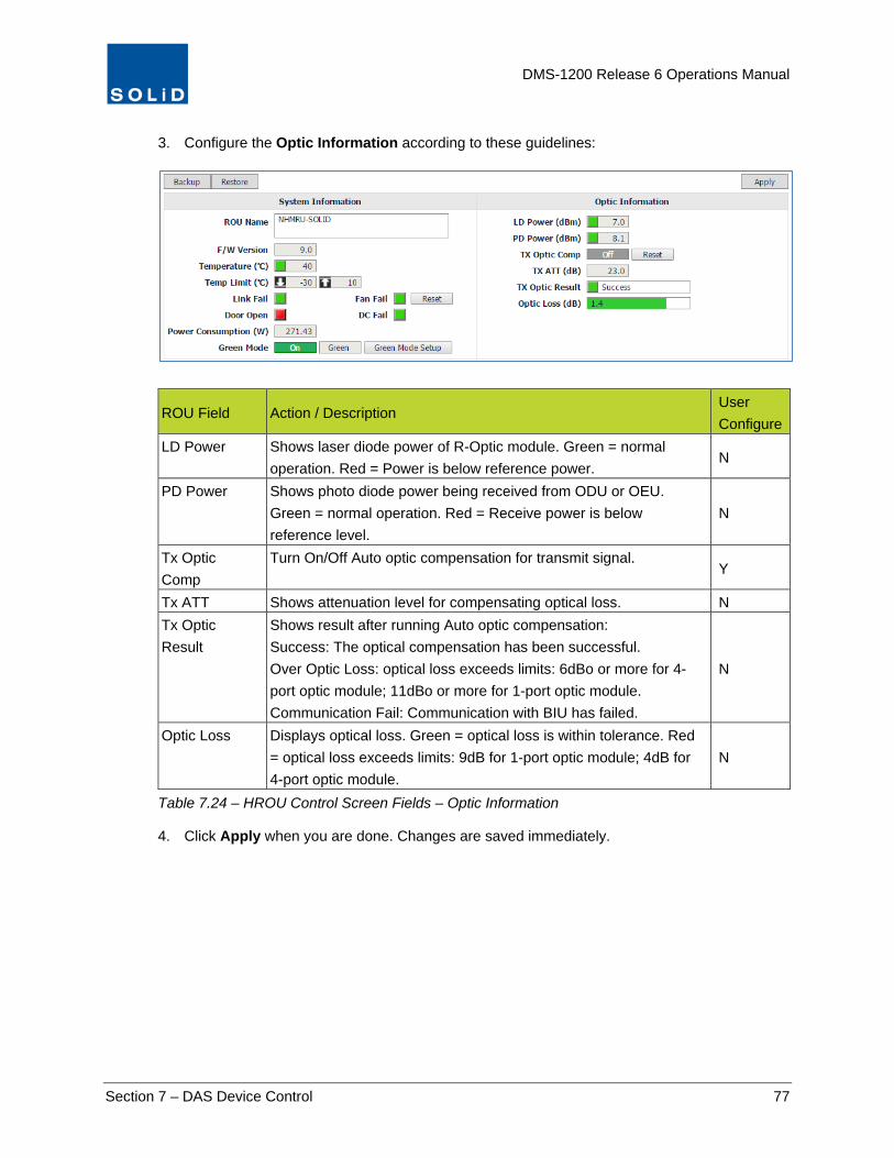
DMS-1200 Release 6 Operations Manual
Section 7 – DAS Device Control 77
3. Configure the Optic Information according to these guidelines:
ROU Field Action / Description User Configure
LD Power Shows laser diode power of R-Optic module. Green = normal operation. Red = Power is below reference power.
N
PD Power Shows photo diode power being received from ODU or OEU. Green = normal operation. Red = Receive power is below reference level.
N
Tx Optic Comp
Turn On/Off Auto optic compensation for transmit signal. Y
Tx ATT Shows attenuation level for compensating optical loss. N Tx Optic Result
Shows result after running Auto optic compensation: Success: The optical compensation has been successful. Over Optic Loss: optical loss exceeds limits: 6dBo or more for 4-port optic module; 11dBo or more for 1-port optic module. Communication Fail: Communication with BIU has failed.
N
Optic Loss Displays optical loss. Green = optical loss is within tolerance. Red = optical loss exceeds limits: 9dB for 1-port optic module; 4dB for 4-port optic module.
N
Table 7.24 – HROU Control Screen Fields – Optic Information
4. Click Apply when you are done. Changes are saved immediately.

DMS-1200 Release 6 Operations Manual
Section 7 – DAS Device Control 78
7.5.8 Green Mode Setup (THOR NHROU Only)
The 20W (THOR) NHROU offers a “Green Mode” setting, which can reduce the remote’s power consumption. Green Mode can be activated by either time of day, TX power levels or both conditions. When Green Mode is on, the power supply unit provides +24V DC to the HRDU; when off, the power unit supplies +29V DC.
5. Configure Green Mode for the 20W THOR NHROU according to these guidelines:
Green Mode Fields Action / Description User
Configure Green Mode Turn Green Mode On / Off. Y Green Mode Setup Click to configure Green Mode. Y
Green Mode Setup
Action / Description User Configure
Green Mode Type
From the pull down menu choose: Time: Green Mode turns on/off at specified time of day. TX Power: Green Mode turns on/off when TX power level falls below / exceeds specified values. Time & TX Power: Green mode activates when both conditions of time and TX power level are met at the same time. Green mode deactivates when either condition is not met.
Y
On Level Set “On” power level. When TX output power level of NHRDU falls below this value, Green Mode is activated. (Default=32dBm)
Y
Off Level Set “Off” power level. When TX output power level of HRDU exceeds this value, Green Mode is disabled. (Default=35dBm)
Y
Start / End Time
Set Start and End times for Green Mode (expressed in 24hr time). Y
Table 7.25 – NHROU Control Screen Fields – Green Mode Setup (NHROU Only)
6. Click Apply when you are done. Changes are saved immediately.

DMS-1200 Release 6 Operations Manual
Section 7 – DAS Device Control 79
7.5.9 NHRDU (THOR) Setup
This section describes how to set up the high-power remote drive units (HRDUs). From the HRDU configuration screens, you can change settings for remote drive units in the HROU and for the external alarm feature.
1. In the Tree Menu or Menu bar, click on the NHROU that contains the NHRDUs you want to configure, then click the tab for the specific NHRDU.
2. Configure the TX settings for the drive unit according to the following guidelines:
TX Values Action / Description User Configure
Tx PLL Lock Tx Phase Locked Loop status. Green = normal. Red = PLL unlocked. N
Tx Out Power Shows Tx output power and Alarm status on that port. Green = normal. Red = output power below / above limits. (Displays --- when no input signal is detected.)
N
Power Limit Set high and low power limits used in Alarm function. Y Tx Out ATT Set attenuation level for Tx output from NHRDU up to 30dB. Y
Tx Out SD This feature is turned On by default. The system shuts down when power output reaches the value in this field. Y
Tx Out ALC Turn On/Off Auto Limit Control. When On, system will apply attenuation when this value is met or exceeded. Y
Tx AGS Turn On/Off Auto Gain Setting. When On, the system sets the output power to the predetermined power level automatically. Y
Tx Out AGS Result
Status of Auto Gain Setting: Success: The AGS function is activated. Not Operate OPTIC Comp: Optic Comp cannot be activated. Lack of ATT: There is no attenuation available.
N
Table 7.26 – NHRDU Control Screen Fields – TX Values

DMS-1200 Release 6 Operations Manual
Section 7 – DAS Device Control 80
3. Configure the RX settings according to these guidelines:
Field Action / Description User Configure
RX Values Rx PLL Lock Rx Phase Locked Loop status. Green = normal. Red = PLL
unlocked. N
Rx In Power Shows Rx input power on that port (±2dB). Displays --- when there is no input detected.
N
Rx In ATT Shows attenuation level applied to Rx input power. N Rx In ALC Turn On/Off Auto Limit Control for input power. Y Tx AMP Turn On/Off high power amplifier. Click Reset to cycle amp power. Y AMP Fail Shows amplifier status. Green = normal. Red = Power amplifier
loop has failed or unexpected low power detected. N
VSWR Shows VSWR (Voltage Standing Wave Ratio) status and level. Green = normal. Red = VSWR level has exceeded the pre-determined threshold.
N
Over Power Shows status of Over Power alarm. Green = normal. Red = Output power level of the power amplifier has exceeded threshold.
N
High Temp Alarm is activated when the temperature of amplifier exceeds 90C N 2.5 TDD Only TDD Sync Shows status of SDM (Sync Detection Module). Green = normal.
Red = module is not communicating properly. N
Band Select Shows which TDD band was selected in the MDBU setup (see page 53): Lower Band, Middle Band or Upper Band.
N
For normal operation, from the drop down list, select Auto. For CW or lab testing, you can use the drop down list to switch between Low Band, Middle Band or Upper Band.
Y
Table 7.27 – NHRDU Control Screen Fields – RX Values
4. Click Apply when you are done. Changes are saved immediately.

DMS-1200 Release 6 Operations Manual
Section 7 – DAS Device Control 81
7.5.10 PIMD Level Measurement (THOR NHROU Only)
The 20W NHROU can measure passive intermodulation (PIMD), a form of intermodulation distortion that can occur in passive components like antenna ports, coaxial connectors and cables. Excessive PIMD can reduce the receive sensitivity of the DAS affecting the system’s reliability, capacity and data rate.
PIMD levels can be tested for each NHRDU in the NHROU. The lowest detectable PIMD level value is -160dBc.
TIP: During PIMD measurement, the system must cut the TX path to generate a CW signal. The process can take up to a minute, during which time the DAS may experience call drops.
1. Click on any of the NHRDU tabs to view the PIMD section of the configuration screen.
2. To check PIMD levels for the NHRDU (#1-#4), click the On/Off toggle until it shows On.
The system will perform the measurement, show the status in the PIMD result field, and show the results in the PIMD Level field as described in the following table.
Field Description User Configure
PIMD Measure On / Off status of PIMD measurement process. Y PIMD Result Idle: PIMD measurement is idle.
Success: The function has properly completed. Lack of ATT: There is no attenuation available. Control Fail: PIMD measurement not available at this time. Retry.
N
PIMD Level Displays measured PIMD level N Table 7.28 – PIMD Measurement

DMS-1200 Release 6 Operations Manual
Section 7 – DAS Device Control 82
7.5.11 External Alarm Setup (THOR NHROU Only)
The NHROU supports an External dry contact alarm feature for both output and input alarms. Output alarms can be sent to any dry contact application.
External ALM #1 supports output alarms. An event indicates active output on the alarm.
When an alarm condition exists, the output relay terminal will operate as shown below.
External ALM Location Conditions ALM In Location Conditions 1 N.O Normally open 4 Input terminal 2 COM - 5 Ground 3 N.C Normally closed Table 7.29 – External Alarm Relay Setup Screen Fields
To Activate Alarms for Dry Contacts
1. From the NHRDU setup screen, click on the External Alarm tab.
2. Check the External ALM and/or In ALM Enable box to activate.
3. For External ALM only, check the Enable box for each condition you would like reported.
4. For In ALM only, click on Active High or Active Low.
In the Active High state, when the contact detects anything other than a ground (zero voltage), such as a voltage or open circuit, the alarm is activated. In the Active Low state, the alarm is activated when a ground is detected.

DMS-1200 Release 6 Operations Manual
Section 7 – DAS Device Control 83
7.6 Upgrading Firmware for DAS Components SOLiD offers periodic firmware upgrades for DAS components. Contact SOLiD Support to obtain firmware files. Update firmware for all system components from the Control > Firmware Download menu.
1. Obtain the latest firmware files from SOLiD Support. Load the firmware on your PC.
2. On the Control menu, click Firmware Download.
3. Click Choose File. Select the firmware file from your PC’s file directory and click Open from the Windows dialog box to confirm.
4. Click File Upload. Uploaded firmware files are shown in the Device / File Name list.
5. From the Device list, select the target device or select multiple devices.
6. From the drop-down list, select the BIU associated with the target devices.
7. Click Download. Status is shown in the progress bar.
8. Once you have updated firmware for a device (for example, all the MDBUs in the system) you can delete the firmware file from the DMS server. Select it, then click Remove.

DMS-1200 Release 6 Operations Manual
Section 7 – DAS Device Control 84
7.7 Backing up and Restoring Device Settings You can save DAS operational settings in a backup file and restore the settings as needed. You can also download a report in spreadsheet format showing current settings for each DAS device.
Backup and Restore are available from the Control screen for each device.
Backup, Restore and Report functions are also available from the Topology window.
7.7.1 Back up DAS settings
1. To make a backup of current DAS control settings, click Backup from the Device Control screen.
2. In the dialog box, enter additional information in the Remark column that will help identify the
backup.
3. Click OK to save the backup file.
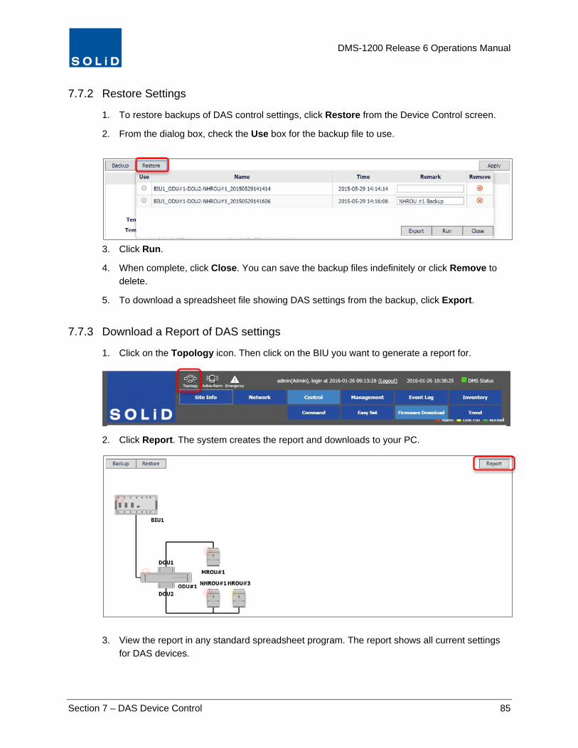
DMS-1200 Release 6 Operations Manual
Section 7 – DAS Device Control 85
7.7.2 Restore Settings
1. To restore backups of DAS control settings, click Restore from the Device Control screen.
2. From the dialog box, check the Use box for the backup file to use.
3. Click Run.
4. When complete, click Close. You can save the backup files indefinitely or click Remove to delete.
5. To download a spreadsheet file showing DAS settings from the backup, click Export.
7.7.3 Download a Report of DAS settings
1. Click on the Topology icon. Then click on the BIU you want to generate a report for.
2. Click Report. The system creates the report and downloads to your PC.
3. View the report in any standard spreadsheet program. The report shows all current settings
for DAS devices.

DMS-1200 Release 6 Operations Manual
Section 8 – System Commissioning with EasySet 86
8 System Commissioning with EasySet EasySet is SOLiD’s quick commissioning solution that supports these functions:
• Auto Setup –set up all automatic functions (i.e., Auto Level Control, Auto Gain Control, Auto Gain Setting) at one time from a single screen.
• System Commissioning – automatically optimize output power levels and optical attenuation according to the settings made in Auto Setup.
• Power Distribution – calculate and set attenuation levels so that the same power levels are allocated to each band.
• Restore Factory Defaults – restore all DAS operating parameters to factory defaults.
All these functions are executed per BIU and affect all components associated with that BIU.
These functions are available to the technician both onsite and through remote connection to the DMS-1200.
In This Section Running Auto Setup
Commissioning the System
Calculating Power Distribution
Restoring Factory Defaults
Related Topics Configure Individual Parameters: Use the DAS device control configuration screens available from the Control > Command menu to set individual parameters for select DAS components

DMS-1200 Release 6 Operations Manual
Section 8 – System Commissioning with EasySet 87
8.1 Commissioning the DAS The Auto Setup function provides a single screen for setting up all automatic functions in the DAS (i.e., Auto Level Control, Auto Gain Control, Auto Gain Setting). The Commissioning function optimizes all system parameters to the user-defined levels set in the Auto Setup process. When executing EasySet with System Commissioning, these system parameters are adjusted together with threshold values and ALC off/on values:
• Execute MDBU TX IN AGC • Execute TX Optic Compensation • AMP “ON” • Execute TX OUT AGS “ON” • PIMD Measurement (NHROU only)
You can also run Auto Setup without executing System Commissioning. See the next section Running Auto Setup without System Commissioning. 1. On the Navigation Bar, click Control > Easy Set
2. From the drop-down list, select a target BIU. This function is executed per BIU and configures all components associated with that BIU.
3. In the check boxes, select the devices to configure.
4. Check the with System Commissioning box.

DMS-1200 Release 6 Operations Manual
Section 8 – System Commissioning with EasySet 88
4. Adjust TX Input and RX Output settings as desired. The following tables offer guidelines for each setting as well as SOLiD recommendations. You can see the Min / Max values for the parameter by clicking in the field.
TIP: SOLiD recommendations offered in the following tables should optimize performance for most deployments, although each site can have unique requirements. Full instructions on performing system commissioning with the DMS1200 can be found in the document: ALLIANCE DAS Tech Note - Commissioning with DMS-1200 available from SOLiD support.
BIU / MDBU Fields
User Configuration SOLiD Recommendation
ALC Turns On/Off Tx Input Auto Level Control. The Input ALC function can be used for neutral host DAS deployments to balance output power of each operator.
Turn off.
TX Input Power High
Sets the high limit for TX input power (±2dB) on that port. (Displays --- when no input signal is detected.) Green = normal. Red = input power above limit and alarm indicated.
Set to 11dBm
TX Input Power Low
Sets the low limit for TX input power (±2dB) on that port. (Displays --- when no input signal is detected.) Green = normal. Red = input power below limit and alarm indicated.
Set to 10~-35dBm
Rx Output ATT
Sets attenuation level applied to Rx gain from the MDBU up to 30dB.
Set to 25dB
Rx Output ALC / Level
On/Off toggle for output Auto Level Control. If on, sets the ALC applied to Rx output from the MDBU.
Turn Off
Rx Output Power High
Sets the high limit for RX output power (±2dB) on that port. (Displays --- when no input signal is detected.) Green = normal. Red = output power above limit and alarm initiated.
Set to 1dBm
Table continues on next page

DMS-1200 Release 6 Operations Manual
Section 8 – System Commissioning with EasySet 89
ROU / RDU Fields
User Configuration SOLiD Recommendation
TX Output ALC / Level
On/Off toggle for Auto Limit Control. When On, system will apply attenuation when this value is met or exceeded.
Turn On. Set to max power output for that band (according to FCC rating).
TX Output AGS Level
On/Off toggle for Auto Gain Setting. When On, the system sets the output power to the predetermined power level automatically.
Set to same value as ALC level.
SD Level The system shuts down when power output reaches the value in this field.
Set to 2dBm above Tx Output ALC level.
Power High High power limit used in Alarm function. Set to 1dBm below the SD level
Power Low Low power limit used in Alarm function. Set to 0dBm Rx Input ALC / Level
On/Off status of Auto Limit Control for input power. Turn On. Set to -50dBm.
Table 8.1 – EasySet Fields
5. When you have finished setting each parameter, click Run to start the Auto Setup /Commissioning process. Check status in the progress bar.
Once complete, the system generates a report with final results.
6. Click Clear to reset or Save to download the report in spreadsheet format.

DMS-1200 Release 6 Operations Manual
Section 8 – System Commissioning with EasySet 90
8.2 Running Auto Setup without System Commissioning When executing EasySet with System Commissioning, all parameters are optimized and the system performs PIMD measurement. This process can take a few minutes, and during this time call drops in the DAS could occur.
If you don’t want to risk service interruption on the DAS, you can use EasySet without also running system commissioning to control levels and values for multiple units at one time.
1. From the drop-down list, select a target BIU.
2. In the check boxes, select the devices to configure. Leave the with System Commissioning box unchecked.
3. Adjust TX Input and RX Output settings as desired.
4. Click Run and OK to confirm.
Status is shown in the progress bar.
Once complete, the system generates a report with final results.
5. Click Clear to reset or Save to download the report in spreadsheet format.

DMS-1200 Release 6 Operations Manual
Section 8 – System Commissioning with EasySet 91
8.3 Calculating Power Distribution The Power Distribution function automatically calculates the attenuation level required to equally distribute TX power levels according to the number of channels and the type of input signal (i.e., 700LTE, 1900, AWS, etc.). For dual BIU configurations, this function will allocate the same amount of power to each band in both the primary and secondary BIU.
TIP: When power distribution function is activated, TX input ALC is turned off.
The following parameters are used for the Power Distribution function:
• Use (On / Off) • TX Power • Number of Carriers (channels) • TX ATT
1. Click Power Distribution.
2. From the drop-down list, select a target BIU.
3. Check the Use box and enter the number of Carriers (channels) associated with each MDBU.
4. In the Percent column etc
5. Click Apply and OK to confirm.
6. Once complete, status is shown in the Result column. Click Refresh to clear the result status
or click Save to download a report in spreadsheet format.

DMS-1200 Release 6 Operations Manual
Section 8 – System Commissioning with EasySet 92
8.4 Restoring Factory Defaults This function resets the parameters for the MDBUs and Remote Units to factory defaults. Factory Set applies to all BIUs and associated remotes in the DAS.
1. Click Factory Set and OK to confirm.
Factory defaults are shown in the next tables.
BIU TX INPUT RX OUTPUT
ALC ON/OFF PWR HIGH PWR-LOW ATT ALC ON/OFF ALC Level
PWR-HIGH
MDBU OFF 11 -25 0 ON 0 1
VHF+UHF OFF 11 -25 0 ON 0 1
Table 8.2 – Factory Defaults (BIU)
Remote Units TX INPUT RX OUTPUT
ROU RDU ALC ON/OFF
ALC LEVEL
AGC LEVEL
SD LEVEL
PWR-HIGH
PWR-LOW
ALC ON/OFF
ALC Level
LROU
1900P ON 26 26 28 27 1 ON -45
AWS-1 ON 26 26 28 27 1 ON -45
All Others ON 23 23 25 24 1 ON -45
MROU 800I+850C ON 40 40 42 41 15 ON -45
All others ON 37 37 39 38 15 ON -45
HROU HRDU ON 43 43 - 45 10 ON -45
Table 8.3 – Factory Defaults (Remote Units)
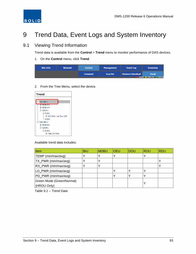
DMS-1200 Release 6 Operations Manual
Section 9 – Trend Data, Event Logs and System Inventory 93
9 Trend Data, Event Logs and System Inventory 9.1 Viewing Trend Information
Trend data is available from the Control > Trend menu to monitor performance of DAS devices.
1. On the Control menu, click Trend.
2. From the Tree Menu, select the device.
Available trend data includes: Item BIU MDBU OEU DOU ROU RDU TEMP (min/max/avg) Y Y Y Y TX_PWR (min/max/avg) Y Y Y RX_PWR (min/max/avg) Y Y Y LD_PWR (min/max/avg) Y Y Y PD_PWR (min/max/avg) Y Y Y Green Mode (Green/Normal) (HROU Only)
Y
Table 9.1 – Trend Data

DMS-1200 Release 6 Operations Manual
Section 9 – Trend Data, Event Logs and System Inventory 94
3. From the Type drop-down list, select the trend you want to see in the graph. These will vary according to the Device.
4. From the Period drop-down list, select the time interval to be used in the graphs X axis – 15 minute or 1 day intervals.
5. Enter the number of Log entries per page.
6. Enter a Date / Time range.
The graph redraws each time you change a search field.
Figure 9.1 – Example Trend Data
7. You can move forward and backward using the scroll feature at the bottom of the graph.
8. Click Save to download a report in spreadsheet format.

DMS-1200 Release 6 Operations Manual
Section 9 – Trend Data, Event Logs and System Inventory 95
9.2 Monitoring System Event Logs The Event Log shows alarm, control, and security events.
1. On the Navigation Bar, click Event Log.
2. Filter the log as desired. Two methods are available.
a. Using the drop-down lists at the top of the window, filter the log according to these guidelines.
Field Description
BIU Filters by BIU, if multiple BIUs are connected to the system.
Device Filters by a specific DAS device (MDBU, ODU, etc.) or all devices.
Level Filters by Alarms at that level and above (more severe). Exact Match filters alarms by just that level. Alarm Levels are defined in the Management > Alarm Control menu.
Type Filters by type of event: Alarm (any Alarm condition), Control (any change to operating parameters for DAS devices), Security (Login and Logout). Leaving all boxes unchecked will return all Alarm types.
Keyword Filters by specified search text. You can also filter by any keyword in the Device, Name, and Message column.
Date / Time Filters by Date / Time range using drop-down calendars.
Table 9.2 − Event Log Filter Criteria

DMS-1200 Release 6 Operations Manual
Section 9 – Trend Data, Event Logs and System Inventory 96
b. To filter by any Keyword in the Name and Message fields, place the cursor over the text in the field. Then click on the text to see the Input keyword dialog box. Click OK to filter.
3. To calculate statistics in bar chart form for the search criteria, click Statistics.
4. To download the Event Log in spreadsheet format, click Save.
5. To reload the log for the BIU selected, click Refresh.

DMS-1200 Release 6 Operations Manual
Section 9 – Trend Data, Event Logs and System Inventory 97
9.3 Viewing the System Inventory The Inventory screen shows all currently connected DAS network components. You can print the inventory and download a file in spreadsheet format.
1. On the Navigation Bar, click Inventory.
2. From the BIU drop down list, select a specific BIU or All to show the inventory for all BIUs
connected to the DMS-1200.
The Inventory fields include:
Field Description
Device Device status: Red = alarm, Yellow = link fail, Green = normal
Band / Name MDBU / RDU band type related to the device (if applicable) and device name. Names are assigned in the Control > Command menu.
TX Power Current TX power (dBm) for the device, if applicable
Firmware Firmware version of the device
Installed Installation date of the device
Serial No. Serial number of the device
Note Click the “+” icon to add any additional information about the device.
Indicates that information has been added. Table 9.3 − Inventory Fields
3. To download a copy in spreadsheet format, click Save.
4. To print a copy of the current inventory report, click Print.
5. To reload the inventory report for the BIU selected, click Refresh.

DMS-1200 Release 6 Operations Manual
Section 10 – SNMP Trap IDs and Alarm Descriptions 98
10 SNMP Trap IDs and Alarm Descriptions The following sections describe the private enterprise management information base (MIB) files provided for SNMP traps and object identifiers (OID). These are used by the DMS-1200 to manage components on the DAS network. Suggested Priority Levels and Hysteresis are shown for each alarm.
TIP: All Trap Names start with “dms1200REL6Alarm” and all the Object IDs start with 1.3.6.1.4.1.35043.1.1.1201. Because of space limitations in this document, the following tables just show the portions of each Trap Name and ID that are unique to the specific alarm.
Object ID (OID): 1.3.6.1.4.1.35043.1.1.1201. Trap Name: dms1200REL6Alarm
OID End
Trap Name End Suggested Priority Level
Suggested Hysteresis (seconds)
Description
4.1 BiuStartup Major (4) 10 System Startup
4.2 BiuHighTemp Major (4) 60 High Temperature Alarm
4.3 BiuLowTemp Minor (3) 60 Low Temperature Alarm
4.4 BiuDcFail Critical (5) 60 Direct Current Failure
4.5 BiuExt1 Warning (2) 60 External Alarm 1
4.6 BiuExt2 Warning (2) 60 External Alarm 2
4.7 BiuExt3 Warning (2) 60 External Alarm 3 (ALM_IN)
4.8 BiuVhfUhfTxHigh Major (4) 60 VHF+UHF TX High Alarm
4.9 BiuVhfUhfTxLow Major (4) 60 VHF+UHF TX Low Alarm
4.10 BiuVhfUhfRxHigh Major (4) 60 VHF+UHF RX High Alarm
4.11 BiuMdbuTxHigh Major (4) 60 MDBU TX High Alarm
4.12 BiuMdbuTxLow Major (4) 60 MDBU TX Low Alarm
4.13 BiuMdbuRxHigh Major (4) 60 MDBU RX High Alarm
4.14 BiuMdbuTxPll Major (4) 60 MDBU TX PLL Alarm
4.15 BiuMdbuRxPll Major (4) 60 MDBU RX PLL Alarm
4.16 BiuLinkFail Major (4) 60 Link Failure
4.17 DouLdFail Critical (5) 60 Laser Diode Failure
4.18 DouPdFail Critical (5) 60 Photo Diode Failure
4.19 BiuMdbuLinkFail Major (4) 60 Link Failure
4.20 OeuHighTemp Major (4) 60 High Temperature Alarm
4.21 OeuLowTemp Minor (3) 60 Low Temperature Alarm
4.22 OeuDcFail Critical (5) 60 Direct Current Failure
4.23 OeuLdFail Critical (5) 60 Laser Diode Failure
4.24 OeuPdFail Critical (5) 60 Photo Diode Failure

DMS-1200 Release 6 Operations Manual
Section 10 – SNMP Trap IDs and Alarm Descriptions 99
Object ID (OID): 1.3.6.1.4.1.35043.1.1.1201. Trap Name: dms1200REL6Alarm
OID End
Trap Name End Suggested Priority Level
Suggested Hysteresis (seconds)
Description
4.25 OeuOpticCompFail Major (4) 60 TX Optic Compensation Fail
4.26 OeuLinkFail Major (4) 60 Link Failure
4.27 LrouHighTemp Major (4) 60 High Temperature Alarm
4.28 LrouLowTemp Minor (3) 60 Low Temperature Alarm
4.29 LrouDcFail Critical (5) 60 Direct Current Failure
4.30 LrouDoorOpen Minor (3) 60 Door Open
4.31 LrouOpticCompFail Major (4) 60 TX Optic Compensation Fail
4.32 LrouLinkFail Major (4) 60 Link Failure
4.33 LrouLdFail Critical (5) 60 Laser Diode Failure
4.34 LrouPdFail Critical (5) 60 Photo Diode Failure
4.35 LrouTxPllUnlock Critical (5) 60 TX PLL Unlock
4.36 LrouRxPllUnlock Critical (5) 60 RX PLL Unlock
4.37 LrouTxHigh Major (4) 60 TX High Alarm
4.38 LrouTxLow Major (4) 60 TX Low Alarm
4.39 LrouTxShutdown Critical (5) 60 TX Shutdown
4.40 MrouHighTemp Major (4) 60 High Temperature Alarm
4.41 MrouLowTemp Minor (3) 60 Low Temperature Alarm
4.42 MrouDcFail Critical (5) 60 Direct Current Failure
4.43 MrouDoorOpen Minor (3) 60 Door Open
4.44 MrouOpticCompFail Major (4) 60 TX Optic Compensation Fail
4.45 MrouLinkFail Major (4) 60 Link Failure
4.46 MrouLdFail Critical (5) 60 Laser Diode Failure
4.47 MrouPdFail Critical (5) 60 Photo Diode Failure
4.48 MrouTxPllUnlock Critical (5) 60 TX PLL Unlock
4.49 MrouRxPllUnlock Critical (5) 60 RX PLL Unlock
4.50 MrouTxHigh Major (4) 60 TX High Alarm
4.51 MrouTxLow Major (4) 60 TX Low Alarm
4.52 MrouTxShutdown Critical (5) 60 TX Shutdown
4.53 MrouAmpFail Major (4) 60 Amplifier Failure
4.54 MrouAmpVswr Major (4) 60 Amplifier VSWR Alarm
4.55 MrouAmpOverPower Major (4) 60 Amplifier Over Power
4.56 HrouHighTemp Major (4) 60 High Temperature Alarm
4.57 HrouLowTemp Minor (3) 60 Low Temperature Alarm
4.58 HrouDcFail Critical (5) 60 Direct Current Failure
4.59 HrouAcFail Critical (5) 60 Alternating Current Failure

DMS-1200 Release 6 Operations Manual
Section 10 – SNMP Trap IDs and Alarm Descriptions 100
Object ID (OID): 1.3.6.1.4.1.35043.1.1.1201. Trap Name: dms1200REL6Alarm
OID End
Trap Name End Suggested Priority Level
Suggested Hysteresis (seconds)
Description
4.60 HrouBatteryLow Critical (5) 60 Battery Low Alarm
4.61 HrouDoorOpen Minor (3) 60 Door Open
4.62 HrouFanFail Major (4) 60 Fan Failure
4.63 HrouOpticCompFail Major (4) 60 TX Optic Compensation Fail
4.64 HrouLinkFail Major (4) 60 Link Failure
4.65 HrouLdFail Critical (5) 60 Laser Diode Failure
4.66 HrouPdFail Critical (5) 60 Photo Diode Failure
4.67 HrouTxPllUnlock Critical (5) 60 TX PLL Unlock
4.68 HrouRxPllUnlock Critical (5) 60 RX PLL Unlock
4.69 HrouTxHigh Major (4) 60 TX High Alarm
4.70 HrouTxLow Major (4) 60 TX Low Alarm
4.71 HrouTxShutdown Critical (5) 60 TX Shutdown
4.72 HrouAmpFail Major (4) 60 Amplifier Failure
4.73 HrouAmpVswr Major (4) 60 Amplifier VSWR Alarm
4.74 HrouAmpOverPower Major (4) 60 Amplifier Over Power
4.75 HrouAmpHighTemp Major (4) 60 High Temperature Alarm
4.76 HrouExtOutAlm Warning (2) 60 ROU External Output
4.77 HrouExtInAlm Warning (2) 60 ROU External Input
4.78 LrouTddSync Critical (5) 60 TDD Synchronization Alarm
4.79 MrouTddSync Critical (5) 60 TDD Synchronization Alarm
4.80 HrouTddSync Critical (5) 60 TDD Synchronization Alarm
4.81 MrouFanFail Major (4) 60 Fan Failure
4.82 LrouAmpFail Major (4) 60 Amplifier Failure
4.83 LrouAmpVswr Major (4) 60 Amplifier VSWR Alarm
4.84 LrouAmpOverPower Major (4) 60 Amplifier Over Power
Table 10.1 – SNMP Traps Object IDs and Trap Names

DMS-1200 Release 6 Operations Manual
Section 11 – Glossary 101
11 Glossary The following terms, acronyms and abbreviations appear in this manual.
AGC Automatic Gain Control. AGC is widely used in communication systems to maintain constant signal strength by varying the amplifier gain.
AGS Automatic Gain Control System
ALC Automatic Level Control
ARU Add on Remote Unit
ATT Attenuation. Reducing signal strength during transmission. Attenuation is the opposite of amplification.
BIU BTS Interface Unit. The unit in the SOLiD DAS topology that receives, combines, and filters all the signal sources, and then sends them to the ODU.
BTS Base Transceiver System
DAS Distributed Antenna System. A network made up of several components that work together to provide wireless service within a building or campus environment.
DMS DAS Management Server. A device for managing, configuring and monitoring a SOLiD DAS system.
DOU Donor Optic Unit.
HARU High Power Add on Remote Unit.
HROU High Power Remote Optic Unit.
LD Laser Diode.
LROU Low Power Remote Optic Unit.
MDBU Main Drive BTS Unit.
MROU Middle Power Remote Optic Unit
MRU Main Remote Unit
NOC Network Operation Center
ODU Optic Distribution Unit. The ODU converts the R F signal to an optical signal and transmits it via fiber to the ROU.
OEU Optic Expansion Unit. The unit in the SOLiD DAS topology that expands a DAS to include multiple buildings and structures using only one strand of fiber.
PD Photo Diode
PLL Phase-Locked Loop
ROU Remote Optic Unit. The unit in the SOLiD DAS topology that amplifies each of the signals individually, and then sends the signals to the antennas via coax.
SD Shutdown

DMS-1200 Release 6 Operations Manual
Section 11 – Glossary 102
SMTP Simple Mail Transfer Protocol
SNMP Simple Network Management Protocol. An IP based protocol for managing devices on an IP network.
SSL Secure Sockets Layer. A protocol for encrypting and transmitting private data via the Internet.
TLS Transport Layer Security
VSWR Voltage Standing Wave Ratio. The ratio between the maximum standing wave amplitude and the minimum standing wave value.