Embed Size (px)
Citation preview

ZXR10 5900/5200 SeriesAll Gigabit-Port Intelligent Routing Switch
User Manual (IPv4 Routing Volume)
Version 2.8.23.A
ZTE CORPORATIONZTE Plaza, Keji Road South,Hi-Tech Industrial Park,Nanshan District, Shenzhen,P. R. China518057Tel: (86) 755 26771900Fax: (86) 755 26770801URL: http://ensupport.zte.com.cnE-mail: [email protected]

LEGAL INFORMATION
Copyright © 2006 ZTE CORPORATION.
The contents of this document are protected by copyright laws and international treaties. Any reproduction or distribution ofthis document or any portion of this document, in any form by any means, without the prior written consent of ZTE CORPO-RATION is prohibited. Additionally, the contents of this document are protected by contractual confidentiality obligations.
All company, brand and product names are trade or service marks, or registered trade or service marks, of ZTE CORPORATIONor of their respective owners.
This document is provided “as is”, and all express, implied, or statutory warranties, representations or conditions are dis-claimed, including without limitation any implied warranty of merchantability, fitness for a particular purpose, title or non-in-fringement. ZTE CORPORATION and its licensors shall not be liable for damages resulting from the use of or reliance on theinformation contained herein.
ZTE CORPORATION or its licensors may have current or pending intellectual property rights or applications covering the subjectmatter of this document. Except as expressly provided in any written license between ZTE CORPORATION and its licensee,the user of this document shall not acquire any license to the subject matter herein.
ZTE CORPORATION reserves the right to upgrade or make technical change to this product without further notice.
Users may visit ZTE technical support website http://ensupport.zte.com.cn to inquire related information.
The ultimate right to interpret this product resides in ZTE CORPORATION.
Revision History
Revision No. Revision Date Revision Reason
R1.2 20091015 Edtion update
Serial Number: sjzl20095128

About This Manual.............................................. i
Static Route Configuration ................................1Static Route Overview..................................................... 1
Configuring Static Route .................................................. 1
Static Route Configuration Example .................................. 2
Static Route Configuration Example............................... 2
Static Route Summary Example.................................... 3
Default Route Configuration Example ............................ 4
Static Route Maintenance and Diagnosis ............................ 5
RIP Configuration..............................................7RIP Overview ................................................................. 7
RIP Basics ................................................................. 7
RIP Routing Metric ...................................................... 7
RIP Timer .................................................................. 8
Route Updates ........................................................... 8
Configuring RIP .............................................................. 9
Enabling RIP .............................................................. 9
Adjusting RIP Timer .................................................... 9
Configuring RIP Neighbor............................................. 9
Configuring RIP Authentication ..................................... 9
Configuring split horizon mechanism ............................10
Configuring Poison Reverse Mechanism.........................10
Redistributing a Route................................................10
Configuring RIP Version ..............................................10
RIP Configuration Example..............................................10
RIP Maintenance and Diagnosis .......................................11
OSPF Configuration .........................................13OSPF Overview .............................................................13
OSPF Basics..............................................................13
OSPF Algorithm.........................................................14
OSPF Network Types ..................................................14
Hello Packet and Timer...............................................15

OSPF Neighbor ..........................................................15
Adjacency and Designated Routers ..............................15
Router Priority and DR Election....................................16
OSPF Area ................................................................16
LSA Type and Flooding ...............................................17
Stub Area and Totally Stub Area ..................................18
Not-So-Stubby Area...................................................18
OSPF Authentication ..................................................19
Configuring OSPF ..........................................................19
Enabling OSPF...........................................................19
Configuring Interface Timer ........................................19
Configuring Interface Cost ..........................................20
Configuring Interface Priority ......................................20
Configuring Neighbor Routers......................................20
Configuring OSPF Area ...............................................20
Configuring Inter-Area Route Aggregation.....................20
Notifying Default Route ..............................................21
Configuring Virtual Link ..............................................21
Redistributing Other Routing Protocols..........................22
Configuring OSPF Authentication..................................22
Enabling Routes to Support Opaque LSA .......................22
Modifying OSPF Management Distance .........................23
OSPF Configuration Example ...........................................23
Basic OSPF Configuration Example ...............................23
Multi-Area OSPF Configuration Example........................24
OSPF Virtual Links Configuration Example .....................25
OSPF Authentication Configuration Example ..................27
OSPF Maintenance and Diagnosis.....................................30
IS-IS Configuration .........................................33IS-IS Overview .............................................................33
IS-IS Overview .........................................................33
IS-IS Area ................................................................34
IS-IS Network Type ...................................................35
DIS and Router Priority ..............................................35
Configuring IS-IS ..........................................................36
Enabling IS-IS ..........................................................36
Configuring IS-IS Global Parameters ............................36
Configuring IS-IS Interface Parameters ........................37
Configuring IS-IS Authentication .................................37
IS-IS Configuration Example ...........................................38

Single Area IS-IS Configuration ...................................38
Multiple Area IS-IS Configuration.................................40
IS-IS Maintenance and Diagnosis.....................................42
BGP Configuration ...........................................45BGP Overview ...............................................................45
Configuring BGP ............................................................46
Enabling BGP ...........................................................46
Configuring BGP Route Advertisement ..........................48
Configuring BGP Aggregate Advertisement ....................48
Configuring Multihop in EBGP ......................................50
Filtering Routes by Router...........................................51
Filtering Routes Using NLRI.........................................51
Filtering Route Based on AS_PATH ...............................52
Setting LOCAL_PREF Attribute .....................................53
Setting MED Attribute ................................................54
Setting Community Attribute.......................................56
Setting BGP Synchronization .......................................56
Setting BGP Router Reflector.......................................58
Setting BGP Confederation..........................................59
Setting BGP Route Dampening ....................................60
BGP Configuration Example.............................................61
BGP Maintenance and Diagnosis ......................................63
Multicast Routing Configuration ......................65Multicast Overview ........................................................65
Multicast Address ......................................................66
IGMP .......................................................................66
Multicast Tree ...........................................................66
PIM-SM ....................................................................67
MSDP.......................................................................68
PIM-SNOOPING.........................................................69
Configuring Public Multicast ............................................69
Configuring IGMP Version ...............................................69
Configuring IGMP Version ...........................................69
Configuring an IGMP Group.........................................70
Configuring IGMP Timer..............................................71
Configuring ssm-mapping ...........................................72
Configuring PIM-SM .......................................................72
Booting PIM-SM.........................................................72
Configuring Static RP Address .....................................72
Configuring Candidate-BSR .........................................73

Configure the Candidate-RP ........................................73
Switching Routers with Directly Connected
Receivers .........................................................73
Configuring the Area Border with the Interface PIM .........74
Setting the RP to Filter the Received Register
Packet..............................................................74
Limiting the BSR Message to Advertise to the
Candidate-RP ....................................................74
Setting DR Priority.....................................................75
Setting the Sending Interval of the Hello Message..........75
Limiting PIM-SM Neighbor...........................................75
Configuring MSDP..........................................................76
Enabling MSDP..........................................................76
Configuring Default MSDP Peer....................................76
Configuring an Originating RP......................................76
Configuring the MSDP Peer as a Mesh Group
Member ...........................................................76
Clearing Statistics Counter for MSDP Peers....................77
Clearing Statistics Counter for MSDP Peers....................77
Clearing Statistics Counter for MSDP Peers....................77
Clearing Statistics Counter for MSDP Peers....................77
Clearing Statistics Counter for MSDP Peers....................78
Configuring PIM-DM.......................................................78
Configuring PIM-SNOOPING ............................................78
Multicast Configuration Example ......................................78
Multicast Maintenance and Diagnosis................................80
Load Balance Configuration.............................87Load Balance Overview ..................................................87
Configuring Load Balance ...............................................88
Load Balance Configuration Example ................................88
Static Routing Load Balance ........................................88
OSPF Load Balance ...................................................90
BGP Load Balance......................................................90
Load Balance Maintenance and Diagnosis..........................91
Figures ............................................................93
Tables .............................................................95
Glossary ..........................................................97

About This Manual
Purpose ZXR10 5900/5200(V2.8.23.A) Series All Gigabit-Port IntelligentRouting Switch User Manual (IPv4 Routing Volume) providesprocedures and guidelines that support the operation on ZXR105900/5200 Series All Gigabit-Port Intelligent Routing Switch,including:
� ZXR10 5924 Gigabit Routing Switch
� ZXR10 5928 Gigabit Routing Switch
� ZXR10 5928–Fi Gigabit Routing Switch
� ZXR10 5952 Gigabit Routing Switch
� ZXR10 5224 Gigabit Convergence Switch
� ZXR10 5228 Gigabit Convergence Switch
� ZXR10 5228–FI Gigabit Convergence Switch
� ZXR10 5252 Gigabit Convergence Switch
� ZXR10 5928–PS Gigabit Convergence Switch
IntendedAudience
This manual is intended for engineers and technicians who per-form operation activities on ZXR10 5900/5200 All Gigabit-Port In-telligent Routing Switches.
Prerequisite Skilland Knowledge
To use the IPv4 Routing volume effectively, users should have ageneral understanding of OSI Model. Familiarity with the followingis helpful,
� Protocols
� Routing concepts and Data Communication Terminologies
What Is in ThisManual
The IPv4 Routing volume contains the following chapters:
TABLE 1 CHAPTER SUMMARY
Chapter Summary
Chapter 1 Static RouteConfiguration
This chapter describes static route and itsconfiguration, including special summarystatic route.
Chapter 2 RIPConfiguration
This chapter describes Routing InformationProtocol (RIP) configuration.
Chapter 3 OSPFConfiguration
This chapter describes Open ShortestPath First (OSPF) protocol and relatedconfiguration.
Chapter 4 IS-ISConfiguration
This chapter describes IS-IS protocol andrelated configuration.
Chapter 5 BGPConfiguration
This chapter describes Border GatewayProtocol (BGP) and related configuration.
Confidential and Proprietary Information of ZTE CORPORATION i

ZXR10 5900/5200 Series User Manual (IPv4 Routing Volume)
Chapter Summary
Chapter 6 MulticastRouting Configuration
This chapter describes Multicast Routingand related configuration.
Chapter 7 Load BalanceConfiguration
This chapter describes Load Balance andrelated configuration.
RelatedDocumentation
The following documentation is related to this manual:
� ZXR10 5900/5200(V2.8.23.A) Series All Gigabit-Port Intelli-gent Routing Switch Hardware Manual
� ZXR10 5900/5200(V2.8.23.A) Series All Gigabit-Port Intelli-gent Routing Switch User Manual (Ethernet Switching Volume)
� ZXR10 5900/5200(V2.8.23.A) Series All Gigabit-Port Intelli-gent Routing Switch User Manual (Basic Configuration Volume)
� ZXR10 5900/5200(V2.8.23.A) Series All Gigabit-Port Intelli-gent Routing Switch User Manual (IPv4 Routing Volume)
� ZXR10 5900/5200(V2.8.23.A) Series All Gigabit-Port Intelli-gent Routing Switch User Manual (IPv6 Routing Volume)
� ZXR10 Router-Ethernet Switch Command Manual - CommandIndex
� ZXR10 Router-Ethernet Switch Command Manual - SystemManagement
� ZXR10 Router-Ethernet Switch Command Manual - FunctionalSystem I
� ZXR10 Router-Ethernet Switch Command Manual - FunctionalSystem Volume II
� ZXR10 Router-Ethernet Switch Command Manual - FunctionalSystem Volume III
� ZXR10 Router/Ethernet Switch Command Manual — FunctionalSystem IV
� ZXR10 Router/Ethernet Switch Command Manual — ProtocolStack I
� ZXR10 Router/Ethernet Switch Command Manual — ProtocolStack II
� ZXR10 Router/Ethernet Switch Command Manual — ProtocolStack III
� ZXR10 Router/Ethernet Switch Information Manual
ii Confidential and Proprietary Information of ZTE CORPORATION

C h a p t e r 1
Static RouteConfiguration
Table of ContentsStatic Route Overview......................................................... 1Configuring Static Route...................................................... 1Static Route Configuration Example ...................................... 2Static Route Maintenance and Diagnosis ................................ 5
Static Route OverviewStatic routes are user-defined routes that cause packets movingbetween a source and a destination to take a specified path. Theyare useful for specifying a gateway of last resort to which, all-un-routable packets will be sent. The static route, unlike a dynamicroute, does not set up the routing table based on routing algo-rithm. When configuring dynamic route, sometimes it is neces-sary to send routing information of the entire Internet to a router,which is hard to bear such great amount of information. In thiscast, it is necessary to use static route.
The static route requires fewer configurations than the dynamicroute. In a routing environment with many routers and paths,however, it is very difficult to configure the static route.
Configuring Static RouteCommand Function
ZXR10(config)#ip route <prefix><net-mask>{<forwarding-router’s-address>|<interface-name>}[global[<distance-metric>][tag <tag>]]
This configures static route.
Confidential and Proprietary Information of ZTE CORPORATION 1

ZXR10 5900/5200 Series User Manual (IPv4 Routing Volume)
Static Route ConfigurationExampleStatic Route Configuration Example
A simple network with three routers connected is shown in Figure1Figure 70.
FIGURE 1 STATIC ROUTE CONFIGURATION
When R1 needs to access network in R3, the static route configu-ration is as follows.ZXR10_R1(config)#ip route 192.168.5.0 255.255.255.0192.168.4.2ZXR10_R1(config)#ip route 192.168.6.0 255.255.255.0192.168.4.2
R2 configuration:ZXR10_R2(config)#ip route 192.168.6.0 255.255.255.0 192.168.5.1ZXR10_R2(config)#ip route 192.168.3.0 255.255.255.0 192.168.4.2
R3 configuration:ZXR10_R3(config)#ip route 192.168.3.0 255.255.255.0 192.168.5.2ZXR10_R3(config)#ip route 192.168.4.0 255.255.255.0 192.168.5.2
It is seen from the above configuration information that static routeis configured in global configuration mode. Only one static routecan be configured once. What next to the command ip route areremote network, subnet mask and next-hop IP address reachingremote network. When R1 wants to transmit message to network192.168.5.0/24, it must deliver the message to R2 with the IP ad-dress of 192.168.4.2; R1 and R2 are connected directly.
When multiple paths to the same destination are available, con-figure the router with multiple static routes with different admin-istrative distance values. Routing table only shows the routinginformation with the minimum distance value. When the router isnotified that there are multiple competitive sources to a network,the route with the minimum administrative distance value has ahigher priority. Parameter <distance-metric> in ip route com-mand can be used to change the administrative distance value ofa static route. Assume that there are two different routes from R1to 192.168.6.0/24 network segment, and the configuration is asfollows:ZXR10_R1(config)#ip route 192.168.6.0 255.255.255.0192.168.4.2ZXR10_R1(config)#ip route 192.168.6.0 255.255.255.0192.168.3.2 25 tag 150
2 Confidential and Proprietary Information of ZTE CORPORATION

Chapter 1 Static Route Configuration
The above two commands configure two different static routes tothe same network. The first command does not configure admin-istrative distance value, so default value 1 is applied. The secondcommand configures the administrative distance value to be 25.
The administrative distance value of the first route is smallerthan that of the second one, so only the information of thefirst route is available in the routing table. That is to say, therouter reaches the destination network 192.168.6.0/24 throughnext-hop 192.168.4.2. The second route will be available inthe routing table only when the first route becomes invalid anddisappears from the routing table.
Static Route Summary Example
Static route is a special static route which summaries two or morespecific route expressions into one expression thus reducing en-tries of the routing table while keeping all of the original connec-tions. Summary static route detail is given in Figure 2.
FIGURE 2 STATIC ROUTE SUMMARY
As shown in Figure 2, R3 has two networks: 10.1.0.0/16 and10.2.0.0/16. To make R1 access these networks, it is necessaryto configure the following two static routes for R1:ZXR10_R1(config)#ip route 10.1.0.0 255.255.0.0192.168.4.2ZXR10_R1(config)#ip route 10.2.0.0 255.255.0.0192.168.4.2
Suppose that R2, R3 has been configured normally, and the aboveconfiguration can be used to complete IP connection. However,static route summary can be used to optimize the routing table ofR1. The following command can be used to replace the above twocommands:ZXR10_R1(config)#ip route 10.0.0.0 255.0.0.0 192.168.4.2
The above command shows that all packets to destination network10.0.0.0/8 pass 192.168.4.2. It means that packets to subnets(subnet 10.1.0.0/16 and subnet 10.2.0.0/16) of the destinationnetwork 10.0.0.0/8 are sent to 192.168.4.2. In this way staticroutes are used to summarize all subnets of the main network10.0.0.0/8.
Confidential and Proprietary Information of ZTE CORPORATION 3

ZXR10 5900/5200 Series User Manual (IPv4 Routing Volume)
Default Route Configuration Example
A router might not be able to determine the routes to all othernetworks. To provide complete routing capability, the commonpractice is to use some routers as smart routers and give the re-maining routers default routes to the smart router. (Smart routershave routing table information for the entire internet work.) Thesedefault routes can be passed along dynamically and can be con-figured into individual routers.
Most dynamic interior routing protocols include a mechanism forcausing a smart router to generate dynamic default informationthat is then passed along to other routers.
If a router cannot route a packet, the packet has to be dropped.However, it is not hoped that the packet is dropped in an "un-known" destination. To support complete connection of the router,it should have a route connected to a network. If the router wantsto keep complete connection and meanwhile does not need torecord each independent route, the default route can be used. Byuse of the default route, an independent route can be designatedto indicate all the other routes.
An example is given in the following to describe the functions anduse of the default route.
FIGURE 3 DEFAULT ROUTE CONFIGURATION
As shown in Figure 3. R2 is connected to router R3 in the Inter-net. R2 does not record the addresses of all the networks on theInternet. It uses a default route to directly send unknown packetsto R3 for proper processing. The configuration of the default routein R2 is as follows:ZXR10_R2(config)#ip route 0.0.0.0 0.0.0.0 211.211.211.2
When the default route is used in routing protocol configuration,the default route varies with the routing protocols.
If the default route is configured for a router where an RIP runs,the RIP will advertise the default route 0.0.0.0/0 to its neighbor,and even route redistribution is not needed in the RIP domain.
For the OSPF protocol, a router where the OSPF protocol runs willnot inject the default route into its neighbor automatically. For theOSPF to send the default route to the OSPF domain command no-tifies default route must be used. If it is necessary to redistributethe default route in the OSPF domain, such an advertisement isnormally implemented by an ASBR (Autonomous System BorderRouter) in the OSPF domain.
4 Confidential and Proprietary Information of ZTE CORPORATION

Chapter 1 Static Route Configuration
The default route configuration is completely the same as the staticroute configuration, and the only difference is that the networkpart and subnet mask part are all 0.0.0.0. This can be seen inrouting table of R2.ZXR10_R2#show ip routeIPv4 Routing Table:Dest Mask Gw Interface Owner pri metric0.0.0.0 0.0.0.0 211.211.211.2 vlan1 static 1 0192.168.4.0 255.255.255.0 192.168.4.2 vlan2 direct0 0192.168.4.2 255.255.255.255 192.168.4.2 vlan2 address0 0
Static Route Maintenanceand Diagnosis
Step Command Function
1 ZXR10#show ip route [<ip-address>[<net-mask>]|<protocol>]
This shows global routingtable of the route and checksif there is any configuredstatic route in the routingtable.
2 ZXR10#show ip forwarding {hostrt <ip-address>|subnetrt <ip-address><net-mask>| summary}
This views hardware routingtable and checks host routeand subnet route of specificIP address and statistics ofsubnet route entry and allhosts.
Confidential and Proprietary Information of ZTE CORPORATION 5

ZXR10 5900/5200 Series User Manual (IPv4 Routing Volume)
This page is intentionally blank.
6 Confidential and Proprietary Information of ZTE CORPORATION

C h a p t e r 2
RIP Configuration
Table of ContentsRIP Overview ..................................................................... 7Configuring RIP .................................................................. 9RIP Configuration Example..................................................10RIP Maintenance and Diagnosis ...........................................11
RIP OverviewRIP Basics
RIP is a relatively old but still commonly used interior gatewayprotocol created for use in small, homogeneous networks. It is aclassical distance-vector routing protocol. RIP is documented inRFC 1058. RIPv2 is defined by RFC2453.
ZXR10 5900/5200 supports RIPv1 and RIPv2 and adopts RIPv2 bydefault. Comparing with RIPv1, RIPv2 has the following advan-tages:
� Subnet mask contained in the routing update
� Authentication of the routing update
� Multicast route update
RIP Routing Metric
RIP uses the UDP packet (port number 520) to exchange RIP rout-ing information. Routing information in the RIP packet includesthe number of routers that a route passes (that is, hops). Routerdetermines the route to the destination network according to hops.RFC stipulates that the maximum hop count cannot go beyond 16,so RIP is only applicable to a small-sized network. Hop count 16indicates the infinite distance and this means that the route is un-reachable. Besides, this is a method for RIP to identify and avoidroute loop.
RIP only takes the hop count as the metric and does not considerthe bandwidth, delay or other variable factors during the routing.RIP always takes the path with the minimum hop count as the
Confidential and Proprietary Information of ZTE CORPORATION 7

ZXR10 5900/5200 Series User Manual (IPv4 Routing Volume)
optimal path which sometimes results in that the selected path isnot the best one.
Administrative Distance (AD) of RIP is 120 by default. Smaller theAD value, more reliable the routing source is. Therefore, compar-ing with other routing protocols, RIP is not so reliable.
RIP Timer
The router running RIP sends a routing information update packetreflecting all the routing information of the router at intervals (30seconds by default), which is called the routing information an-nouncement. If a router cannot receive update information fromanother router within a period of time (180 seconds by default),it will label the route provided by this router as unavailable. Ifupdate information still cannot be received within the subsequentperiod of time (240 seconds), the router eliminates the route fromthe routing table. Holddown timer introduces a certain amount ofskepticism to reduce the acceptance of bad routing information. Ifthe distance to a destination increases, for example, the hop countincreases from two to four, the router sets a holddown timer forthat route. Until the timer expires, the router will not accept anynew updates for the route.
RIP provides four timers:
� Update timer
� Invalid timer
� Holddown timer
� Flush timer
Route Updates
RIP sends routing-update messages at regular intervals and whennetwork topology changes. When a router receives a routing up-date that includes changes to an entry, it updates its routing tableto reflect the new route. The metric value for path is increased by1, and the sender is indicated as the next hop. RIP routers onlymaintain best route (the route with the lowest metric value) to adestination.
After updating its routing table, router immediately transmits rout-ing updates to inform other network routers of the change. Theseupdates are sent independently of the regularly scheduled updatesthat RIP routers send.
8 Confidential and Proprietary Information of ZTE CORPORATION

Chapter 2 RIP Configuration
Configuring RIPEnabling RIP
Step Command Function
1 ZXR10#ZXR10(config)#router rip This enables RIP.
2 ZXR10(config-router)#network <ip-address><net-mask>
This associates a networkwith RIP routing process.
Adjusting RIP Timer
Command Function
ZXR10(config-router)#timers basic <update><invalid><holddown><flush>
This adjusts timer for better RIPperformance.
Configuring RIP Neighbor
Command Function
ZXR10(config-router)#neighbor <ip-address> This configures neighbor routerwhich exchanges routinginformation with this router.
Configuring RIP Authentication
To specify the type of authentication used in RIP Version 2 packets,designate the key for interface simple text authentication, use thefollowing command.
Step Command Function
1 ZXR10(config-if-vlanX)#ip rip authentication key<key>
This designates the keyfor interface simple textauthentication.
2 ZXR10(config-if-vlanX)#ip rip authentication mode{text|md5}
This designates theauthentication type forRIP packet.
Confidential and Proprietary Information of ZTE CORPORATION 9

ZXR10 5900/5200 Series User Manual (IPv4 Routing Volume)
Configuring split horizon mechanism
Command Function
ZXR10(config-if-vlanX)# ip split-horizon This enables the split horizonmechanism.
Configuring Poison ReverseMechanism
Command Function
ZXR10(config-if-vlanX)#ip poison-reverse This enables the poison reversemechanism.
Redistributing a Route
Command Function
ZXR10(config-router)#redistribute <protocol>[metric<metric-value>][route-map <map-tag>]
This redistributes a route fromanother routing domain to triprouting domain.
Configuring RIP Version
ZXR10 5900/5200 supports RIPv1 and RIPv2. RIPv2 is adopts bydefault.
Step Command Function
1 ZXR10(config-router)#version{1|2} This designates the global RIPversion of the router.
2 ZXR10(config-if-vlanX)#ip rip receive version{1|2}[1|2]
This designates the RIPversion received by theinterface.
3 ZXR10(config-if-vlanX)#ip rip send version {1|2{broadcast|multicast}}
This designates the RIPversion sent by the interface.
RIP Configuration ExampleAs shown in Figure 4, RIP runs on router R1 and router R2.
10 Confidential and Proprietary Information of ZTE CORPORATION

Chapter 2 RIP Configuration
FIGURE 4 BASIC RIP CONFIGURATION
R1 Configuration:ZXR10_R1(config)#router ripZXR10_R1(config-router)#network 10.1.0.0 0.0.255.255ZXR10_R1(config-router)#network 192.168.1.0 0.0.0.255ZXR10_R1(config-router)#no auto-summary
R2 configuration:ZXR10_R2(config)#router ripZXR10_R2(config-router)#network 10.2.0.0 0.0.255.255ZXR10_R2(config-router)#network 192.168.1.0 0.0.0.255ZXR10_R1(config-router)#no auto-summary
The result is viewed as follows:ZXR10_R2(config)#show ip rip databaseRoutes of rip:h : is possibly down,in holddown timef : out holddown time before flush
Dest Metric RtPrf Time From*> 10.2.0.0/16 0 0 00:00:00 0.0.0.0*> 10.1.0.0/16 2 120 00:00:09 192.168.1.1*> 192.168.1.0/24 0 0 00:00:00 0.0.0.0
RIP Maintenance andDiagnosisZXR10 5900/5200 provides show command for RIP maintenanceand diagnosis.
Step Command Function
1 ZXR10#show ip rip This displays protocolinformation.
2 ZXR10#show ip rip interface <interface-name> This shows rip routinginterface and its parametersinformation.
3 ZXR10#show ip rip database This displays the entirerouting entry database.
4 ZXR10#show ip rip networks This displays all the RIPinterfaces configured byusers.
Confidential and Proprietary Information of ZTE CORPORATION 11

ZXR10 5900/5200 Series User Manual (IPv4 Routing Volume)
Step Command Function
5 ZXR10#show ip route [<ip-address><net-mask>] rip This displays global routingtable and if RIP is in therouting table.
6 ZXR10#show ip forwarding subnetrt <ip-address><net-mask>
This displays driving hardwarerouting table and if hardwarerouting table is same as globalrouting table.
ZXR10 5900/5200 also provides debug command for RIP mainte-nance and diagnosis.
Step Command Function
1 ZXR10#debug ip rip This traces the basic RIPsending and receiving packet.
2 ZXR10#debug ip rip database This traces the changeprocess of the RIP routingtable.
This example shows a debug output example of the debug ip ripcommand.ZXR10#debug ip ripRIP protocol debugging is onZXR10#11:01:28: RIP: building update entries130.1.0.0/16 via 0.0.0.0, metric 1, tag 0130.1.1.0/24 via 0.0.0.0, metric 1, tag 0177.0.0.0/9 via 0.0.0.0, metric 1, tag 0193.1.168.0/24 via 0.0.0.0, metric 1, tag 0197.1.0.0/16 via 0.0.0.0, metric 1, tag 0199.2.0.0/16 via 0.0.0.0, metric 1, tag 0202.119.8.0/24 via 0.0.0.0, metric 1, tag 0
11:01:28: RIP: sending v2 periodic update to 224.0.0.9 viavlan10 (193.1.1.111)130.1.0.0/16 via 0.0.0.0, metric 1, tag 0130.1.1.0/24 via 0.0.0.0, metric 1, tag 0177.0.0.0/9 via 0.0.0.0, metric 1, tag 0193.1.1.0/24 via 0.0.0.0, metric 1, tag 0
11:01:28: RIP: sending v2 periodic update to 193.1.168.95via vlan20 (193.1.168.111)11:01:28: RIP: sending v2 periodic update to 193.1.168.86via vlan20 (193.1.168.111)11:01:28: RIP: sending v2 periodic update to 193.1.168.77via vlan20 (193.1.168.111)11:01:28: RIP: sending v2 periodic update to 193.1.168.68via vlan20 (193.1.168.111)
12 Confidential and Proprietary Information of ZTE CORPORATION
C h a p t e r 3
OSPF Configuration
Table of ContentsOSPF Overview .................................................................13Configuring OSPF ..............................................................19OSPF Configuration Example ...............................................23OSPF Maintenance and Diagnosis.........................................30
OSPF OverviewOSPF Basics
Open Shortest Path First (OSPF) is one of the most popular andwidely used routing protocols. OSPF is a replacement for the prob-lematic Routing Information Protocol (RIP) and other distance vec-tor protocols. OSPF major advantage is that it supports for muchlarger inter-networks and less susceptibility to bad routing infor-mation.
OSPF Version 1 is defined by RFC1131. OSPF Version 2 is definedby RFC2328 and presently in use. ZXR10 5900/5200 fully supportsOSPF Version 2.
OSPF has the following features:
� OSPF contains the flow of routing protocol traffic and makespossible construction of hierarchical inter-network topologies.
� There is no routing loop. The shortest path first (SPF) algo-rithm ensures a loop free network.
� Route aggregation decreases the routing table size.
� Support of classless route table lookups, Variable Length Sub-net Mask (VLSM) and Classless Inter-Domain Routing (CIDR).
� Less network bandwidth is needed because the adopted updatetrigger mechanism sends update information only when thenetwork topology changes.
� Support of authentication for more secure routing.
� Update information can be multicasted instead of being broad-casted, which reduces the impact on irrelevant network de-vices.
Confidential and Proprietary Information of ZTE CORPORATION 13

ZXR10 5900/5200 Series User Manual (IPv4 Routing Volume)
OSPF Algorithm
As OSPF is a link state protocol. OSPF router generates a routingtable by setting up a link state database, which contains the infor-mation of all networks and routers. Routers use this informationto establish routing tables. To ensure reliability, all routers musthave the same link state database.
Link state database is built, based on Link State Advertisements(LSAs) ,which are generated by all routers and spread over thewhole OSPF network. There are many types of LSAs, a completeLSA set shows an accurate distribution diagram over the wholenetwork.
OSPF uses cost as the metric. The cost is distributed to each portof a router. A port calculates the cost, that is based on a 100Mbenchmark by default. The path cost to a particular destination isthe total cost of all links between the router and the destination.
To generate a routing table, based on the LSA database, a routerruns the Dijkstra SPF algorithm to construct a cost routing treewith itself as the root of the routing tree. The Dijkstra algorithmenables a router to calculate the lowest-cost path between itselfand any node on the network. Router saves the routes of the pathsin the routing table.
Different from RIP, OSPF does not simply broadcast all of its routinginformation regularly. An OSPF router sends call messages to itsneighbors to let them know it is still alive. If a router does notreceive any message from a neighbor within a period of time thenthe neighbor might not be alive.
OSPF routing is incrementally updated. Router sends the updateinformation only when topology changes. When the age of an LSAreaches 1800 seconds, a new version of the LSA is resent.
OSPF Network Types
Type of the network connecting to a port is used to determine thedefault OSPF behavior on that port. The network type affects theadjacency relationship and how the router designates a timer tothe port.
There are five network types in OSPF, and they are as follows:
� Broadcast
� Non-broadcast Multi-access (NBMA) networks
� Point-to-Point networks
� Point-to-multipoint networks
� Virtual links
14 Confidential and Proprietary Information of ZTE CORPORATION

Chapter 3 OSPF Configuration
Hello Packet and Timer
Hello protocol serves several purposes:
� It is the means by which neighbors are discovered.
� It advertises several parameters on which two routers mustagree before they can become neighbors.
� Hello packets act as keepalives between neighbors.
� It ensures bi-directional communication between neighbors.
� It elects designated routers and backup designated routers onBroadcast and Nonbroadcast Multiaccess (NBMA) networks.
OSPF uses three types of timers related to the Hello Packet.
HelloInterval is an attribute of an interface. It defines the lengthof time between Hello Packets that the router sends on the inter-face. Default HelloInterval depends on the network type. On thebroadcast and point-to-point networks the default HelloInterval is10 seconds. On NBMA and point-to-multipoint networks it is 30seconds. The router’s neighbor routers must agree on the Hel-loInterval to enable them to become neighbors.
It is number of seconds before the router’s neighbors will declareit down. When they stop receiving the router’s Hello Packets. Thedefault RouterDeadInterval is four times as long as the HelloInt-erval, which applies to all the network types.
PollInterval is only used on the NBMA network.
OSPF Neighbor
OSPF neighbors are a group of routers on the same network. Theyhave some of the same configuration parameters. Routers mustfirst be neighbors before they can set up adjacency relationship.
Routers analyze the Hello Packets from each other when they be-come neighbors to make sure the required parameters are stipu-lated. Parameters include area ID, area flag, authentication infor-mation, HelloInterval and RouterDeadInterval.
Adjacency and Designated Routers
Two routers when set up adjacency relationship. They can ex-change routing information. Whether two routers can set up anadjacency relationship depends on the type of the network con-necting the routers.
There are only two routers in point-to-point network and virtuallinks. Routers set up an adjacency relationship automatically. Thepoint-to-multipoint network can be regarded as a set of point-to-point networks. Each pair of routers set up an adjacency relation-ship automatically.
Confidential and Proprietary Information of ZTE CORPORATION 15

ZXR10 5900/5200 Series User Manual (IPv4 Routing Volume)
Neighbors do not necessarily have the adjacency relationship, onbroadcast and NBMA networks. If all routers (the number is n)on a network have set up the adjacency relationship, each routerhas (n-1) adjacency relationships and there are n (n-1)/2 adja-cency relationships on the network. Tracking so many adjacencyrelationships on a large multi-access network will impose a heavyburden on each router. Routing information between each pair ofneighbor routers will waste a great deal of network bandwidth.
OSPF defines a Designated Router (DR) and a Backup DesignatedRouter (BDR). Designated Router (DR) has following duties:
� To represent a multi-access network and it’s attached routersto the rest of the internetwork.
� To manage the flooding process on the multi-access network.
DR and BDR must establish an adjacency relationship with eachOSPF router over the network. Each OSPF router only establishesadjacency relationships with DR and BDR. If the DR stops workingthen BDR take its place and becomes DR.
Router Priority and DR Election
Each multi-access interface of each router has a Router Priority,which is an 8-bit unsigned integer ranging from 0 to 255. Defaultpriority is 1.
During the DR election, the router with the highest priority be-comes the DR. If all routers have the same priority, the one withthe highest IP address will be elected as the DR. Routers with apriority of 0 are ineligible to become the DR or BDR.
OSPF Area
A network is divided into several smaller OSPF areas to reduce theinformation that each router stores and maintains. Each routermust have the complete information of its area. Areas can sharetheir information. Routing information can be filtered out on thearea edge to reduce the routing information stored in routers.
Each area is identified by a 32-bit unsigned number. Area 0 is usedto identify the backbone area. All the other areas must directlyconnect to Area 0. An OSPF network must have one backbonearea. Based on its tasks in the area, a router can be of one ormultiple of the following roles, as shown in Figure 5 .
16 Confidential and Proprietary Information of ZTE CORPORATION

Chapter 3 OSPF Configuration
FIGURE 5 OSPF ROUTER TYPES
� Internal router: Router’s interface is in the same area.
� Backbone router: Router has at least one interface in Area 0.
� Area Border Router (ABR): Router has at least one interface inArea 0 and at least one interface in another area.
� Autonomous System Border Router (ASBR): Router connectsan AS that runs OSPF to another AS that runs another protocol,such as RIP and IGRP.
LSA Type and Flooding
OSPF routers useLSAs to exchange information for the link statedatabase. LSAs set up an accurate and complete network diagramroutes in a routing table. ZXR10 5900/5200 supports six types ofLSAs:
� Type 1Router LSA
� Type 2Network LSA
� Type 3Network Summary LSA
� Type 4ASBR Summary LSA
� Type 5AS External LSA
� Type 7NSSA External LSA
OSPF operations are determined by all routers that share one pub-lic link state database in a region. Therefore all LSAs need to beflooded over the region and the processing must be reliable. Eachrouter sends the LSAs that it receives from a particular area to theother interfaces in the area. Instead of being packets, LSAs arecontained in Link State Update (LSU) packets. Several LSAs can beincluded in one LSU. When a router receives an LSU packet insteadof forwarding it directly, router extracts LSAs from the packet andputs them into its database. In addition, the router constructs its
Confidential and Proprietary Information of ZTE CORPORATION 17

ZXR10 5900/5200 Series User Manual (IPv4 Routing Volume)
own LSU and forwards the modified LSU to neighbors connectingto it.
OSPF sends Link State Acknowledgements (LSAck) to make surethat each LSA is received by neighbors. An LSAck contains thehead of the confirmed LSA, which is sufficient for identifying anLSA uniquely. When a router sends an LSA to an interface, theLSA is recorded in the resend queue of the interface. Router willwait the preset time for the LSAck of the LSA. If it does not receivethe LSAck within the preset time, it will resend the LSA. A routercan send the original LSU by both unicast and multicast but canresend the LSU only by unicast.
Stub Area and Totally Stub Area
A stub area is an area into which AS External LSAs are not flooded.If type 5 LSAs are not known inside an area, type 4 LSAs areunnecessary; these LSAs are blocked. ABRs at the edge of a stubarea will use Network Summary LSAs to advertise a single defaultroute into the area.
In a stub area, all routers must be configured as stub routers.Hello Packet contains a “stub area” flag bit, which must be consis-tent among neighbors.
ABR in a stub area can filter out type 5 LSAs to prevent themfrom being advertised to the stub area. In addition, the ABR willgenerate a type 3 LSA to advertise a default route to destinationaddresses outside the AS.
ABR also filters out the Type 3 LSAs and advertises a default routeto destination addresses outside of the area, this area is calledtotally stubby area.
Not-So-Stubby Area
Routers in a stub area do not allow type 5 LSAs so the ASBR is notpart of a stub area. To create a stub area with ASBR, routers inthis area receive from the ASBR the routes outside of the AS butexternal routing information from other areas is blocked.
Not-so-stubby area (NSSA) allows external routes to be advertisedinto the OSPF autonomous system while retaining the character-istics of a sub area to the rest of the autonomous system. Todo this, the ASBR in an NSSA originates type 7 LSAs to advertisethe external destinations. These NSSA External LSAs are floodedthroughout the NSSA but are blocked at the ABR. On the otherhand, it converts type 7 LSAs into type 5 LSAs.
18 Confidential and Proprietary Information of ZTE CORPORATION

Chapter 3 OSPF Configuration
OSPF Authentication
Authentication applies to packet exchange between OSPF neigh-bors. Neighbors must agree on the authentication type, which isincluded in all packets.
When simple password authentication is configured, one interfacecan have only one password and each interface can have a differ-ent passwords all interfaces in a particular network must have thesame password. Simple password is transmitted in plain text byOSPF packets.
Configuring OSPFEnabling OSPF
Command Function
ZXR10(config)#router ospf <process-id> This enables OSPF routing.
Configuring Interface Timer
Step Command Function
1 ZXR10(config-if-vlanX)#ip ospf hello-interval<seconds>
This designates an intervalat which an interface sendsHello packets.
2 ZXR10(config-if-vlanX)#ip ospf retransmit-interval<seconds>
This designates the interval atwhich an interface retransmitsan LSA.
3 ZXR10(config-if-vlanX)#ip ospf transmit-delay<seconds>
This designates the delayafter which an interfacetransmits a LSU packet.
4 ZXR10(config-if-vlanX)#ip ospf dead-interval<seconds>
This designates the deadinterval for a neighbor on aninterface.
Confidential and Proprietary Information of ZTE CORPORATION 19

ZXR10 5900/5200 Series User Manual (IPv4 Routing Volume)
Configuring Interface Cost
Command Function
ZXR10(config-if-vlanX)#ip ospf cost<cost> This configures interface cost.
Configuring Interface Priority
Command Function
ZXR10(config-if-vlanX)#ip ospf priority<priority> This configures interface priority.
Configuring Neighbor Routers
Command Function
ZXR10(config-router)#neighbor <ip-address>[cost<cost>][priority <priority>][poll-interval <seconds>]
This designates the neighborrouters on a non-broadcast.
Configuring OSPF Area
OSPF uses area to implement the hierarchical routing. OSPF areasare divided into stub area, totally stubby area and not-so-stubbyarea. Backbone area is a transitional area.
Step Command Function
1 ZXR10(config-router)#area <area-id> stub[no-summary][default-cost <cost>]
This defines an area as a stubarea or totally stubby area.
2 ZXR10(config-router)#area < area-id> nssa [no-redistribution][ default-information-originate[ metric < metric-value>][ metric-type < type>][no-redistribution ][ no-summary ]][ no-summary]
This defines an area as anot-so-stubby area.
Configuring Inter-Area RouteAggregation
Route aggregation can occur between areas or autonomous sys-tems (AS). Inter-area route aggregation takes place on the ABRwhereas inter-AS route aggregation happens on the ASBR.
20 Confidential and Proprietary Information of ZTE CORPORATION

Chapter 3 OSPF Configuration
Configuring a stub area can save resources on routers in the stubarea but it does not help the backbone area.
If network addresses in an area are allocated in sequence, config-ure ABR to advertise an aggregate route to replace the sequentialroutes. Route aggregation can save resources in the backbonearea by advertising a summary address for a group of networkaddresses.
Command Function
ZXR10(config-router)#area <area-id> range<ip-address><net-mask>[advertise|not-advertise]
This configures the range ofsummary addresses in the area.
Notifying Default Route
When a router uses redistributed routes it becomes an ASBR. ASBRdoes not automatically advertise the default route to the wholeOSPF area by default.
Command Function
ZXR10(config-router)#notify default route [always][metric <metric-value>][metric-type <type>][route-map<map-tag>]
This notifies default route.
Configuring Virtual Link
All areas on an OSPF network must directly connect to the back-bone area, which will set a limit to the layout of areas especiallywhen the network is very large. To overcome this problem, a vir-tual link can be used to connect a remote area to the backbonearea through another area. The area that the virtual link crossesmust have complete routing information, so it cannot be a stubarea.
Command Function
ZXR10(config-router)#area < area-id> virtual-link< router-id>[ hello-interval < seconds>][retransmit-intervall < seconds>][ transmit-delay< seconds>][ dead-intervall < seconds>][authentication-key < key>][ message-digest-key <keyid> md5 < cryptkey>[ delay < time>][ encrypt ]][authentication [ null| message-digest]]
This defines an OSPF virtual link.
Confidential and Proprietary Information of ZTE CORPORATION 21

ZXR10 5900/5200 Series User Manual (IPv4 Routing Volume)
Redistributing Other RoutingProtocols
Different dynamic routing protocols can share routing informationthrough route redistribution. In OSPF the routing information ofother routing protocols is the external routing information of an AS.Only when the AS’s external routing information is redistributed toOSPF then it can spread it to the whole OSPF network.
Command Function
ZXR10(config-router)#redistribute <protocol>[as <as-number>][peer <peer-address>][tag <tag-value>][metric<metric-value>][metric-type <type>][route-map<map-tag>]
This control the redistribution ofroutes of other routing protocolsto the OSPF.
Configuring OSPF Authentication
In order to improve the security of routing processes, OSPF au-thentication can be configured on router.
Step Command Function
1 ZXR10(config-router)#area <area-id> authentication[message-digest]
This performs authenticationon the OSPF area.
2 ZXR10(config-if-vlanX)#ip ospf authentication-key<password>
This sets a password for theinterface of simple passwordauthentication.
Enabling Routes to Support OpaqueLSA
During the exchange of link state database, opaque LSAs are in-cluded in the database summary list and transmitted to the neigh-bor routers that also support opaque LSAs.
A router before it floods opaque LSAs to neighbor routers. It firstchecks whether the neighbor routers support opaque LSAs or not.Opaque LSAs are transmitted only to the neighbor routers thatsupport the function and they will be added to the link state re-transmit list of neighbor routers. When LSU packets are multicas-ted the neighbor routers that do not support the function receivethe LSAs passively and simply discard them.
Command Function
ZXR10(config-router)#capability opaque This enables routes to supportopaque LSAs.
22 Confidential and Proprietary Information of ZTE CORPORATION
Chapter 3 OSPF Configuration
Modifying OSPF ManagementDistance
Management distance is related to the reliability of the routing in-formation source. Management distance is an integer between 0and 255. Higher value represents lower reliability. If the manage-ment distance is 255, the routing information source is unreliableand the related routes will be ignored.
Command Function
ZXR10(config-router)#distance ospf {[internal<distance>][ext1 <distance>][ext2 <distance>]}
This defines the OSPF routemanagement distance based onthe route type.
OSPF ConfigurationExampleBasic OSPF Configuration Example
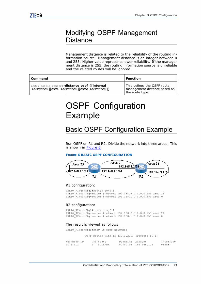
Run OSPF on R1 and R2. Divide the network into three areas. Thisis shown in Figure 6.
FIGURE 6 BASIC OSPF CONFIGURATION
R1 configuration:ZXR10_R1(config)#router ospf 1ZXR10_R1(config-router)#network 192.168.2.0 0.0.0.255 area 23ZXR10_R1(config-router)#network 192.168.1.0 0.0.0.255 area 0
R2 configuration:ZXR10_R2(config)#router ospf 1ZXR10_R2(config-router)#network 192.168.3.0 0.0.0.255 area 24ZXR10_R2(config-router)#network 192.168.1.0 0.0.0.255 area 0
The result is viewed as follows:ZXR10_R1(config)#show ip ospf neighbor
OSPF Router with ID (10.1.2.1) (Process ID 1)
Neighbor ID Pri State DeadTime Address Interface10.1.1.2 1 FULL/DR 00:00:36 192.168.1.2 vlan8
Confidential and Proprietary Information of ZTE CORPORATION 23

ZXR10 5900/5200 Series User Manual (IPv4 Routing Volume)
ZXR10_R2(config)#show ip ospf neighbor
OSPF Router with ID (10.1.1.2) (Process ID 1)
Neighbor ID Pri State DeadTime Address Interface10.1.2.1 1 FULL/BDR 00:00:30 192.168.1.1 vlan8
Multi-Area OSPF ConfigurationExample
When a network is big, it should be divided into multiple OSPFareas. This is shown in Figure 7 as an example of multi-area OSPF.
FIGURE 7 MULTI-AREA OSPF CONFIGURATION
1. Area 0.0.0.1 is a NSSA; R1 is an ABR working between theNSSA 0.0.0.1 and the backbone area. R1 advertises a defaultroute in the local area.
R1 configuration:ZXR10_R1(config)#interface vlan 1ZXR10_R1(config-if-vlan1)#ip address 10.0.1.1 255.255.255.252ZXR10_R1(config-if-vlan1)#exitZXR10_R1(config)#interface vlan2ZXR10_R1(config-if-vlan2)#ip address 10.0.0.1 255.255.255.0ZXR10_R1(config-if-vlan2)#exitZXR10_R1(config)#router ospf 1ZXR10_R1(config-router)#network 10.0.0.0 0.0.0.255 area 0.0.0.0ZXR10_R1(config-router)#network 10.0.1.0 0.0.0.3 area 0.0.0.1ZXR10_R1(config-router)#area 0.0.0.1 nssa default-information-originate
2. Area 0.0.0.2 is a stub area; R2 is an ABR working between theArea 0.0.0.2 and the backbone area. In the stub area, the ABRadvertises a default route automatically.
R2 configuration:ZXR10_R2(config)#interface vlan1ZXR10_R2(config-if-vlan1)#ip address 10.0.2.1 255.255.255.252ZXR10_R2(config-if-vlan1)#exitZXR10_R2(config)#interface vlan2
24 Confidential and Proprietary Information of ZTE CORPORATION

Chapter 3 OSPF Configuration
ZXR10_R2(config-if-vlan2)#ip address 10.0.0.2 255.255.255.0ZXR10_R2(config-if-vlan2)#exitZXR10_R2(config)#router ospf 1ZXR10_R2(config-router)#network 10.0.0.0 0.0.0.255 area 0.0.0.0ZXR10_R2(config-router)#network 10.0.2.0 0.0.0.3 area 0.0.0.2ZXR10_R2(config-router)#area 0.0.0.2 stub
3. R3 is a router in the backbone area 0 and connects to otherASs through a BGP. R3 Configuration can be done as egressrouter of the whole as to advertise a default route to the entireOSPF area manually.
R3 configuration:ZXR10_R3(config)#interface vlan1ZXR10_R3(config-if-vlan1)#ip address 10.0.0.3 255.255.255.0ZXR10_R3(config-if-vlan1)#exitZXR10_R3(config)#interface vlan2ZXR10_R3(config-if-vlan2)#ip address 192.168.0.1 255.255.255.0ZXR10_R3(config-if-vlan2)#exitZXR10_R3(config)#router ospf 1ZXR10_R3(config-router)#network 10.0.0.0 0.0.0.255 area 0.0.0.0ZXR10_R3(config-router)#notify default route always
4. R4 is the ASBR in NSSA 0.0.0.1. Both OSPF and RIP run onR4. Routes of RIP can be redistributed to OSPF.
R4 configuration:ZXR10_R4(config)#interface vlan1ZXR10_R4(config-if-vlan1)#ip address 192.168.1.1 255.255.255.0ZXR10_R4(config-if-vlan1)#exitZXR10_R4(config)#interface vlan2ZXR10_R4(config-if-vlan2)#ip address 10.0.1.2 255.255.255.252ZXR10_R4(config-if-vlan2)#exitZXR10_R4(config)#router ospf 1ZXR10_R4(config-router)#network 10.0.1.0 0.0.0.3 area 0.0.0.1ZXR10_R4(config-router)#area 0.0.0.1 nssaZXR10_R4(config-router)#redistribute rip metric 10
5. R5 is a router in stub area 0.0.0.2.
R5 configuration:ZXR10_R5(config)#interface vlan1ZXR10_R5(config-if-vlan1)#ip address 10.0.2.2 255.255.255.252ZXR10_R5(config-if-vlan1)#exitZXR10_R5(config)#router ospf 1ZXR10_R5(config-router)#network 10.0.2.0 0.0.0.3 area 0.0.0.2ZXR10_R5(config-router)#area 0.0.0.2 stub
Use the show ip ospf neighbor command to ensure if neighboris established.
OSPF Virtual Links ConfigurationExample
An OSPF virtual link is shown in Figure 8
Confidential and Proprietary Information of ZTE CORPORATION 25

ZXR10 5900/5200 Series User Manual (IPv4 Routing Volume)
FIGURE 8 OSPF VIRTUAL LINK
R1 configuration:ZXR10_R1(config)#interface vlan1ZXR10_R1(config-if-vlan1)#ip address 10.0.0.1 255.255.255.0ZXR10_R1(config-if-vlan1)#exitZXR10_R1(config)#router ospf 1ZXR10_R1(config-router)#network 10.0.0.0 0.0.0.255 area 0.0.0.0
R2 configuration:ZXR10_R2(config)#interface vlan1ZXR10_R2(config-if-vlan1)#ip address 10.0.0.2 255.255.255.0ZXR10_R2(config-if-vlan1)#exitZXR10_R2(config)#interface vlan2ZXR10_R2(config-if-vlan2)#ip address 10.0.1.1 255.255.255.252ZXR10_R2(config-if-vlan2)#exitZXR10_R2(config)#router ospf 1ZXR10_R2(config-router)#network 10.0.0.0 0.0.0.255 area 0.0.0.0ZXR10_R2(config-router)#network 10.0.1.0 0.0.0.3 area 0.0.0.1ZXR10_R2(config-router)#area 1 virtual-link 10.0.1.2
R3 configuration:ZXR10_R3(config)#interface vlan1ZXR10_R3(config-if-vlan1)#ip address 10.0.1.2 255.255.255.252ZXR10_R3(config-if-vlan1)#exitZXR10_R3(config)#interface vlan2ZXR10_R3(config-if-vlan2)#ip address 10.0.2.1 255.255.255.0ZXR10_R3(config-if-vlan2)#exitZXR10_R3(config)#router ospf 1ZXR10_R3(config-router)#network 10.0.1.0 0.0.0.3 area 0.0.0.1ZXR10_R3(config-router)#network 10.0.2.0 0.0.0.255 area 0.0.0.2ZXR10_R3(config-router)#area 1 virtual-link 10.0.0.2
The result is viewed as follows:ZXR10_R2(config)#show ip ospf virtual-linksVirtual Link to router 10.0.1.2 is UPUp for 00:01:57 (Demand circuit, Suppress hello)Transit area 0.0.0.1via interface vlan8 10.0.1.1State PTOP, Transmit Delay(sec) 1,Cost 1, Authentication Type null
26 Confidential and Proprietary Information of ZTE CORPORATION

Chapter 3 OSPF Configuration
Timer intervals(sec) : Hello 10, Dead 40, Retransmit 5Adjacency State FULLDead time : no use Options : 0x62In Full State for 00:01:47
ZXR10_R3(config)#show ip ospf virtual-linksVirtual Link to router 10.0.0.2 is UPUp for 00:00:08 (Demand circuit)Transit area 0.0.0.1via interface vlan8 10.0.1.2State PTOP, Transmit Delay(sec) 1,Cost 1, Authentication Type nullTimer intervals(sec) : Hello 10, Dead 40, Retransmit 5Adjacency State INITDead time : 00:00:37 Options : 0x22In Full State for 00:00:00
OSPF Authentication ConfigurationExample
Plain text authentication is adopted in Area 0, MD5 encrypted au-thentication is used in Area 1. This is shown in Figure 9.
FIGURE 9 OSPF AUTHENTICATION
R1 configuration:ZXR10_R1(config)#interface vlan1ZXR10_R1(config-if-vlan1)#ip address 10.0.0.1 255.255.255.0ZXR10_R1(config-if-vlan1)#ip ospf authentication-key ZXR10ZXR10_R1(config-if-vlan1)#exitZXR10_R1(config)#router ospf 1ZXR10_R1(config-router)#network 10.0.0.0 0.0.0.255 area 0.0.0.0ZXR10_R1(config-router)#area 0 authentication
R2 configuration:ZXR10_R2(config)#interface vlan1ZXR10_R2(config-if-vlan1)#ip address 10.0.0.2 255.255.255.0ZXR10_R2(config-if-vlan1)#ip ospf authentication-key ZXR10ZXR10_R2(config-if-vlan1)#exitZXR10_R2(config)#interface vlan2ZXR10_R2(config-if-vlan2)#ip address 10.0.1.1 255.255.255.252
Confidential and Proprietary Information of ZTE CORPORATION 27

ZXR10 5900/5200 Series User Manual (IPv4 Routing Volume)
ZXR10_R2(config-if-vlan2)#ip ospf message-digest-key 1 md5 ZXR10ZXR10_R2(config-if-vlan2)#exitZXR10_R2(config)#router ospf 1ZXR10_R2(config-router)#network 10.0.0.0 0.0.0.255 area 0.0.0.0ZXR10_R2(config-router)#network 10.0.1.0 0.0.0.3 area 0.0.0.1ZXR10_R2(config-router)#area 0 authenticationZXR10_R2(config-router)#area 1 authentication message-digest
R3 configuration:ZXR10_R3(config)#interface vlan1ZXR10_R3(config-if-vlan1)#ip address 10.0.1.2 255.255.255.252ZXR10_R3(config-if-vlan1)#ip ospf message-digest-key 1 md5 ZXR10ZXR10_R3(config-if-vlan1)#exitZXR10_R3(config)#router ospf 1ZXR10_R3(config-router)#network 10.0.1.0 0.0.0.3 area 0.0.0.1ZXR10_R3(config-router)#area 1 authentication message-digest
The result is viewed as follows:ZXR10_R1(config)#show ip ospf 1OSPF 1 enableRouter ID 10.1.1.1Domain ID type 0x5,value 0.0.0.1Enabled for 02:32:48,Debug onNumber of areas 3, Normal 3, Stub 0, NSSA 0Number of interfaces 1Number of neighbors 1Number of adjacent neighbors 1Number of virtual links 0Total number of entries in LSDB 11Number of ASEs in LSDB 0, Checksum Sum 0x00000000Number of grace LSAs 0Number of new LSAs received 16Number of self originated LSAs 112Hold time between consecutive SPF 1 secsNon-stop Forwarding disabled, last NSF restart 02:39:27 ago (took 0 secs)
Area 0.0.0.0 enable (Demand circuit available)Enabled for 02:31:56Area has simple password authenticationTimes spf has been run 22Number of interfaces 1. Up 1Number of ASBR local to this area 0Number of ABR local to this area 2Total number of intra/inter entries in LSDB 4. Checksum Sum 0x00028590Area-filter out not setArea-filter in not setArea ranges count 0
Area 0.0.0.1 enable (Demand circuit available)Enabled for 01:29:29Area has no authenticationTimes spf has been run 27Number of interfaces 0. Up 0Number of ASBR local to this area 0Number of ABR local to this area 1Total number of intra/inter entries in LSDB 4. Checksum Sum 0x0002a5bcArea-filter out not setArea-filter in not setArea ranges count 0
Area 0.0.0.23 enable (Demand circuit available)Enabled for 02:32:28Area has no authenticationTimes spf has been run 45Number of interfaces 0. Up 0Number of ASBR local to this area 0Number of ABR local to this area 1Total number of intra/inter entries in LSDB 3. Checksum Sum 0x0001cf91Area-filter out not setArea-filter in not setArea ranges count 0
28 Confidential and Proprietary Information of ZTE CORPORATION

Chapter 3 OSPF Configuration
ZXR10_R2(config)#show ip ospf 1OSPF 1 enableRouter ID 10.0.1.2Domain ID type 0x5,value 0.0.0.1Enabled for 01:46:47,Debug onNumber of areas 3, Normal 3, Stub 0, NSSA 0Number of interfaces 2Number of neighbors 1Number of adjacent neighbors 1Number of virtual links 0Total number of entries in LSDB 12Number of ASEs in LSDB 0, Checksum Sum 0x00000000Number of grace LSAs 0Number of new LSAs received 16Number of self originated LSAs 31Hold time between consecutive SPF 1 secsNon-stop Forwarding disabled, last NSF restart 01:49:58 ago (took 0 secs)
Area 0.0.0.0 enable (Demand circuit available)Enabled for 01:44:59Area has simple password authenticationTimes spf has been run 5Number of interfaces 1. Up 1Number of ASBR local to this area 0Number of ABR local to this area 2Total number of intra/inter entries in LSDB 4. Checksum Sum 0x00028391Area-filter out not setArea-filter in not setArea ranges count 0
Area 0.0.0.1 enable (Demand circuit available)Enabled for 01:46:26Area has MD5 authenticationTimes spf has been run 15Number of interfaces 1. Up 1Number of ASBR local to this area 0Number of ABR local to this area 1Total number of intra/inter entries in LSDB 5. Checksum Sum 0x0002c08eArea-filter out not setArea-filter in not setArea ranges count 0
Area 0.0.0.2 enable (Demand circuit available)Enabled for 01:46:07Area has no authenticationTimes spf has been run 3Number of interfaces 0. Up 0Number of ASBR local to this area 0Number of ABR local to this area 1Total number of intra/inter entries in LSDB 3. Checksum Sum 0x0001e787Area-filter out not setArea-filter in not setArea ranges count 0
ZXR10_R3(config)#show ip ospf 1OSPF 1 enableRouter ID 10.0.1.2Domain ID type 0x5,value 0.0.0.1Enabled for 00:00:58,Debug onNumber of areas 1, Normal 1, Stub 0, NSSA 0Number of interfaces 1Number of neighbors 0Number of adjacent neighbors 0Number of virtual links 0Total number of entries in LSDB 1Number of ASEs in LSDB 0, Checksum Sum 0x00000000Number of grace LSAs 0Number of new LSAs received 0Number of self originated LSAs 1Hold time between consecutive SPF 1 secs
Confidential and Proprietary Information of ZTE CORPORATION 29

ZXR10 5900/5200 Series User Manual (IPv4 Routing Volume)
Non-stop Forwarding disabled, last NSF restart 00:14:15 ago (took 0 secs)
Area 0.0.0.1 enable (Demand circuit available)Enabled for 00:00:12Area has MD5 authenticationTimes spf has been run 1Number of interfaces 1. Up 0Number of ASBR local to this area 0Number of ABR local to this area 0Total number of intra/inter entries in LSDB 1. Checksum Sum 0x00008e9aArea-filter out not setArea-filter in not setArea ranges count 0
OSPF Maintenance andDiagnosisZXR10 5900/5200 provides show command for maintenance anddiagnosis.
Step Command Function
1 ZXR10#show ip ospf This views OSPF processdetail.
2 ZXR10#show ip ospf interface [<interface-name>][process <process-id>]
This checks the currentconfiguration and state of anOSPF interface.
3 ZXR10#show ip ospf neighbor [interface <interface-name>][neighbor-id <neighbor>][process<process-id>]
This checks the information ofOSPF neighbors.
4 ZXR10#show ip ospf database This displays all or part of theinformation of the link statedatabase.
5 ZXR10#show ip route ospf This displays router globalrouting table and views ifOSPF route is in routing table.
6 ZXR10#show ip forwarding subnetrt <ip-address><net-mask>
This views driving hardwarerouting table and view ifhardware routing table issame as global routing table.
ZXR10 5900/5200 also provides debug command for maintenanceand diagnosis.
Step Command Function
1 ZXR10#debug ip ospf adj This enables OSPF adjacencyrelationship debugging.
30 Confidential and Proprietary Information of ZTE CORPORATION

Chapter 3 OSPF Configuration
Step Command Function
2 ZXR10#debug ip ospf packet This enables OSPF packettransmission, receiptdebugging, listen to receiptand transmission of all OSPFpackets.
3 ZXR10#debug ip ospf lsa-generation This enables OSPF LSAgeneration debugging.
4 ZXR10#debug ip ospf events This enables OSPF importantevents debugging.
Confidential and Proprietary Information of ZTE CORPORATION 31

ZXR10 5900/5200 Series User Manual (IPv4 Routing Volume)
This page is intentionally blank.
32 Confidential and Proprietary Information of ZTE CORPORATION
C h a p t e r 4
IS-IS Configuration
Table of ContentsIS-IS Overview .................................................................33Configuring IS-IS ..............................................................36IS-IS Configuration Example ...............................................38IS-IS Maintenance and Diagnosis.........................................42
IS-IS OverviewIS-IS Overview
Intermediate System-to-Intermediate System (IS-IS) is a routingprotocol that is introduced by the International Organization forStandardization (ISO) for Connectionless Network Service (CLNS).IS-IS works on the network layer of the Open Systems Intercon-nection (OSI). When IS-IS is expanded and added with the func-tion to support IP routing, it becomes Integrated IS-IS. IS-IS in-troduced in this document refers to Integrated IS-IS.
IS-IS is widely used as an Interior Gateway Protocol (IGP) on net-works. On the surface, OSPF and IS-IS have many features incommon:
� They both maintain a link state database from which a Dijkstra-based SPF algorithm computers a shortest-path tree.
� They both use Hello packets to form and maintain adjacencies.
� They both use areas to form a two-level hierarchical topology.
� They both have the capability of providing address summariza-tion between areas.
� They both are classless protocols.
� They both have authentication capabilities.
Since the IS-IS protocol is based on CLNS (not IP), IS-IS usesProtocol Data Unit (PDU) defined by ISO to implement communi-cations among routers. The types of PDUs used in IS-IS protocolare as follows:
� Call PDU
� Link state PDU (LSP)
� Sequence Number PDU (SNP)
Confidential and Proprietary Information of ZTE CORPORATION 33

ZXR10 5900/5200 Series User Manual (IPv4 Routing Volume)
Where, call PDU is similar to the HELLO packet in the OSPF pro-tocol, which is responsible for the formation of the adjacency be-tween routers, discovery of new neighbors and the detection ofexit of any neighbors.
IS-IS routers exchange routing information, set up and maintainlink state database by use of link state PDUs. An LSP indicatesimportant information about a router, covering area and connectednetwork. SNP is used to ensure reliable transmission of LSPs. SNPcontains summary information about each LSP on a network.
When a router receives an SNP, it compares SNP with link statedatabase. If router loses an LSP in SNP, it originates a multicastSNP and asks for necessary LSPs from other routers on the net-work. LSPs are used in conjunction with SNPs so that IS-IS pro-tocol can complete reliable route interaction on a large network.
Likewise, the IS-IS protocol also uses Dijkstra SPF algorithm tocalculate routes. Based on the link state database, the IS-IS pro-tocol uses SPF algorithm to calculate the best route and then addsthe route to the IP routing table.
IS-IS Area
For convenience of link-state database management, concept ofIS-IS area is introduced. Routers in an area are only responsiblefor maintaining the link state database in the local area to reducethe traffic of the routers themselves.
IS-IS areas are classified into backbone areas and non-backboneareas:
� Routers in the backbone area have the information about thedatabase of the entire network.
� Routers in a non-backbone area only have information aboutthe area.
Based on the area division, IS-IS defines three types of routers:
� Level 1 router exists in a non-backbone area and only ex-changes routing information with L1 router and L1/L2 routerin the area.
� Level 2 router exists in the backbone area and exchanges rout-ing information with other L2 routers and L1/L2 routers.
� Level 1/Level 2 routers exist in a non-backbone area and ex-changes routing information between non-backbone area andthe backbone area.
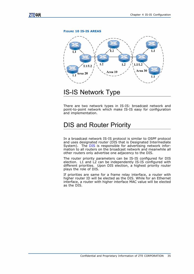
This IS-Is area division and router types are shown in Figure 10.
34 Confidential and Proprietary Information of ZTE CORPORATION
Chapter 4 IS-IS Configuration
FIGURE 10 IS-IS AREAS
IS-IS Network Type
There are two network types in IS-IS: broadcast network andpoint-to-point network which make IS-IS easy for configurationand implementation.
DIS and Router Priority
In a broadcast network IS-IS protocol is similar to OSPF protocoland uses designated router (DIS that is Designated IntermediateSystem). The DIS is responsible for advertising network infor-mation to all routers on the broadcast network and meanwhile allother routers only advertise one adjacency to the DIS.
The router priority parameters can be IS-IS configured for DISelection. L1 and L2 can be independently IS-IS configured withdifferent priorities. Upon DIS election, a highest priority routerplays the role of DIS.
If priorities are same for a frame relay interface, a router withhigher router ID will be elected as the DIS. While for an Ethernetinterface, a router with higher interface MAC value will be electedas the DIS.
Confidential and Proprietary Information of ZTE CORPORATION 35

ZXR10 5900/5200 Series User Manual (IPv4 Routing Volume)
Configuring IS-ISEnabling IS-IS
Command Function
ZXR10(config)# router isis This enables the IS-IS routingprocess.
Configuring IS-IS Global Parameters
IS-IS parameter configuration covers global parameters and inter-face parameters. IS-IS global parameters need to be configuredin the IS-IS route mode.
1. To define the operation type, use the following command.
Command Function
ZXR10(config-router)#is-type {level-1|level-1-2|level-2-only}
This defines the operation type.
2. To define PSNP (Sequence Number PDU) for point to point net-works, use the following command.
Command Function
ZXR10(config-if-vlanX)#isis psnp-interval <interval>[level-1|level-2]
This defines PSNP (SequenceNumber PDU) for point to pointnetworks.
3. To notify insufficient resources of router running as IS-IS pro-tocol, use the following command.
Command Function
ZXR10(config-router)#set-overload-bit This notifies insufficientresources of router runningas IS-IS protocol.
4. To configure the policy for advertising the default route, usethe following command.
Command Function
ZXR10(config-router)#default-information originate[always][metric <metric-value>][metric-type<type>][level-1|level-1-2|level-2]
This configures the policy foradvertising the default route.
36 Confidential and Proprietary Information of ZTE CORPORATION

Chapter 4 IS-IS Configuration
5. To summarize entries in IS-IS routing table, use the followingcommand.
Command Function
ZXR10(config-router)#summary-address < ip-address><net-mask>[metric]< metric-value>[[ level-1| level-1-2|level-2][metric]< metric-value>]
This summarizes entries in IS-ISrouting table.
Configuring IS-IS InterfaceParameters
Interface IS-IS parameters need to be configures on the interfacerunning IS-IS.
Step Command Function
1 ZXR10(config-if-vlanX)#isis circuit-type{level-1|level-1-2|level-2-only}
This designates an operationtypes for an interface.
2 ZXR10(config-if-vlanX)#isis hello-interval<interval>[level-1|level-2]
This defines an interval foradjacent routers hello packet.
3 ZXR10(config-if-vlanX)#isis hello-multiplier<multiplier>[level-1|level-2]
This configures isishello-multiplier in orderto save time for sending hellopackets.
4 ZXR10(config-if-vlanX)#isis lsp-interval<interval>[level-1|level-2]
This sets time interval fortransmitting LSP packets.
5 ZXR10(config-if-vlanX)#isis retrasmit-interval<interval>[level-1|level-2]
This sets LSP packetretransmission internal.
6 ZXR10(config-if-vlanX)#isis priority <priority>[level-1|level-2]
This designates DIS electionpriority of an interface.
7 ZXR10(config-if-vlanX)#isis metric <metric-value>[level-1|level-2]
This configures IS-IS metricof an interface to participatein calculation for number ofshortest IS-IS paths.
8 ZXR10(config-if-vlanX)#isis csnp-interval<interval>[level-1|level-2]
This configures IS-IS CSNPinterval in order to setthe interval between CSNPpackets.
Configuring IS-IS Authentication
ZXR10 5900/5200 supports plain text authentication and MD5 en-cryption authentication.
Confidential and Proprietary Information of ZTE CORPORATION 37

ZXR10 5900/5200 Series User Manual (IPv4 Routing Volume)
Step Command Function
1 ZXR10(config-if-vlanX)#isis authentication-type{text|md5}[level-1|level-2]
This sets the authenticationmethod for an interface.
2 ZXR10(config-router)#authentication-type{text|md5}[level-1|level-2]
This sets the authenticationmethod for LSP packets.
For each authentication modeZXR10 5900/5200 supports threetype authentication modes
Step Command Function
1 ZXR10(config-if-vlanX)#isis authentication<key>[level-1|level-2]
This sets interfaceauthentication.
2 ZXR10(config-router)#authentication<key>[level-1|level-2]
This sets LSP authentication.
3 ZXR10(config-router)#enable-snp-authentication This sets SNP authentication.
Configure SNP authentication, and the authentication characterstring is “welcome”.ZXR10(config)#router isisZXR10(config-router)#authentication welcomeZXR10(config-router)#enable-snp-authentication
IS-IS Configuration ExampleSingle Area IS-IS Configuration
Before configuring IS-IS, it is necessary to analyze whole network,plan network topology and to decide whether it is necessary todivide the network into areas or not. Run multiple routing proto-cols on the network according to the network size. The followingexample shows the basic configuration of IS-IS on a single-areanetwork. This is shown in Figure 11.
FIGURE 11 SINGLE AREA CONFIGURATION
38 Confidential and Proprietary Information of ZTE CORPORATION

Chapter 4 IS-IS Configuration
In the above figure, R1 and R2 form Area 1 and they run IS-IS.
R1 configuration:ZXR10_R1(config)#router isisZXR10_R1(config-router)#area 01ZXR10_R1(config-router)#system-id 00D0.D0C7.53E0ZXR10_R1(config-router)#exitZXR10_R1(config)#interface vlan4ZXR10_R1(config-if-vlan4)#ip address 192.168.2.1 255.255.255.0ZXR10_R1(config-if-vlan4)#ip router isisZXR10_R1(config)#interface vlan6ZXR10_R1(config-if-vlan6)#ip address 192.168.1.1 255.255.255.0ZXR10_R1(config-if-vlan6)#ip router isis
R2 configuration:ZXR10_R2(config)#router isisZXR10_R2(config-router)#area 01ZXR10_R2(config-router)#system-id 00D0.D0C7.5460ZXR10_R2(config-router)#exitZXR10_R2(config)#interface vlan4ZXR10_R2(config-if-vlan4)#ip address 192.168.2.2 255.255.255.0ZXR10_R2(config-if-vlan4)#ip router isisZXR10_R2(config)#interface vlan3ZXR10_R2(config-if-vlan3)#ip address 192.168.6.1 255.255.255.0ZXR10_R2(config-if-vlan3)#ip router isis
The result is viewed as follows:ZXR10_R1(config#show isis adjacencyInterface System id State Lev Holds SNPA(802.2) Pri MTvlan8 ZXR10 UP/UP L1L2 28/28 0000.1000.0009 64/64
ZXR10_R1(config#show ip routeIPv4 Routing Table:Dest Mask Gw Interface Owner Pri Metric10.1.1.0 255.255.255.0 10.1.1.2 vlan10 direct 0 010.1.1.2 255.255.255.255 10.1.1.2 vlan10 address 0 0192.168.1.0 255.255.255.0 192.168.1.1 vlan24 direct 0 0192.168.1.1 255.255.255.255 192.168.1.1 vlan24 address 0 0192.168.2.0 255.255.255.0 192.168.2.1 vlan8 direct 0 0192.168.2.1 255.255.255.255 192.168.2.1 vlan8 address 0 0192.168.6.0 255.255.255.0 192.168.2.2 vlan8 isis-l1 115 20
ZXR10_R2(config)#show isis adjacencyInterface System id State Lev Holds SNPA(802.2) Pri MTvlan8 ZXR10 UP/UP L1L2 8/8 0019.8310.2321 64/64
ZXR10_R2(config)#show ip routeIPv4 Routing Table:Dest Mask Gw Interface Owner pri metric10.1.1.0 255.255.255.0 10.1.1.3 vlan1 direct 0 010.1.1.3 255.255.255.255 10.1.1.3 vlan1 address 0 0192.168.1.0 255.255.255.0 192.168.2.1 vlan8 isis-l1 115 20192.168.2.0 255.255.255.0 192.168.2.2 vlan8 direct 0 0192.168.2.2 255.255.255.255 192.168.2.2 vlan8 address 0 0192.168.6.0 255.255.255.0 192.168.6.1 vlan24 direct 0 0192.168.6.1 255.255.255.255 192.168.6.1 vlan24 address 0 0
Confidential and Proprietary Information of ZTE CORPORATION 39

ZXR10 5900/5200 Series User Manual (IPv4 Routing Volume)
Multiple Area IS-IS Configuration
If a network is large, then divide IS-IS network into multiple areas.Routers in a geographic area or of similar functions can be put intoone area. This reduces the demand on memory. Routers in an areaonly need to maintain a small link state database. This is showninFigure 12.
FIGURE 12 MULTIPLE AREA IS-IS CONFIGURATION
R1 is in Area 1. R2, R3, and R4 are in Area 0. R5 and R6 are inArea 2. Segments in Area 1 are aggregated on R1. The defaultroute is redistributed to IS-IS on R6.
R1 configuration:ZXR10_R1(config)#router isisZXR10_R1(config-router)#area 01ZXR10_R1(config-router)#system-id 00D0.D0C7.53E0ZXR10_R1(config-router)#is-type LEVEL-1-2ZXR10_R1(config-router)#exitZXR10_R1(config)#interface vlan4ZXR10_R1(config-if-vlan4)#ip address 192.168.15.1 255.255.255.0ZXR10_R1(config-if-vlan4)#ip router isisZXR10_R1(config-if-vlan4)#isis circuit-type LEVEL-2ZXR10_R1(config-if-vlan4)#exitZXR10_R1(config)#interface vlan6ZXR10_R1(config-if-vlan6)#ip address 192.168.100.1 255.255.255.0ZXR10_R1(config-if-vlan6)#ip router isisZXR10_R1(config-if-vlan6)#isis circuit-type LEVEL-1ZXR10_R1(config-if-vlan6)#exitZXR10_R1(config)#interface vlan7ZXR10_R1(config-if-vlan7)#ip address 192.168.101.1 255.255.255.0ZXR10_R1(config-if-vlan7)#ip router isisZXR10_R1(config-if-vlan7)#isis circuit-type LEVEL-1ZXR10_R1(config-if-vlan7)#exitZXR10_R1(config)#interface vlan8ZXR10_R1(config-if-vlan8)#ip address 192.168.102.1 255.255.255.0ZXR10_R1(config-if-vlan8)#ip router isisZXR10_R1(config-if-vlan8)#isis circuit-type LEVEL-1ZXR10_R1(config-if-vlan8)#exitZXR10_R1(config)#router isisZXR10_R1(config-router)#summary-address 192.168.100.0 255.255.252.0 metric 10
R2 configuration:
40 Confidential and Proprietary Information of ZTE CORPORATION

Chapter 4 IS-IS Configuration
ZXR10_R2(config)#router isisZXR10_R2(config-router)#area 00ZXR10_R2(config-router)#system-id 00D0.E0D7.53E0ZXR10_R2(config-router)#is-type LEVEL-2ZXR10_R2(config-router)#exitZXR10_R2(config)#interface vlan4ZXR10_R2(config-if-vlan4)#ip address 192.168.10.2 255.255.255.0ZXR10_R2(config-if-vlan4)#ip router isisZXR10_R2(config-if-vlan4)#isis circuit-type LEVEL-2ZXR10_R2(config-if-vlan4)#exitZXR10_R2(config)#interface vlan6ZXR10_R2(config-if-vlan6)#ip address 192.168.12.2 255.255.255.0ZXR10_R2(config-if-vlan6)#ip router isisZXR10_R2(config-if-vlan6)#isis circuit-type LEVEL-2ZXR10_R2(config-if-vlan6)#exit
R3 configuration:ZXR10_R3(config)#router isisZXR10_R3(config-router)#area 00ZXR10_R3(config-router)#system-id 00D0.E0C7.53E0ZXR10_R3(config-router)#is-type LEVEL-2ZXR10_R3(config-router)#exitZXR10_R3(config)#interface vlan4ZXR10_R3(config-if-vlan4)#ip address 192.168.15.3 255.255.255.0ZXR10_R3(config-if-vlan4)#ip router isisZXR10_R3(config-if-vlan4)#isis circuit-type LEVEL-2ZXR10_R3(config-if-vlan4)#exitZXR10_R3(config)#interface vlan6ZXR10_R3(config-if-vlan6)#ip address 192.168.10.3 255.255.255.0ZXR10_R3(config-if-vlan6)#ip router isisZXR10_R3(config-if-vlan6)#isis circuit-type LEVEL-2ZXR10_R3(config)#interface vlan7ZXR10_R3(config-if-vlan7)#ip address 192.168.11.3 255.255.255.0ZXR10_R3(config-if-vlan7)#ip router isisZXR10_R3(config-if-vlan7)#isis circuit-type LEVEL-2ZXR10_R3(config-if-vlan7)#exit
R4 configuration:ZXR10_R4(config)#router isisZXR10_R4(config-router)#area 00ZXR10_R4(config-router)#system-id 00D0.E0E7.53E0ZXR10_R4(config-router)#is-type LEVEL-2ZXR10_R4(config-router)#exitZXR10_R4(config)#interface vlan4ZXR10_R4(config-if-vlan4)#ip address 192.168.12.4 255.255.255.0ZXR10_R4(config-if-vlan4)#ip router isisZXR10_R4(config-if-vlan4)#isis circuit-type LEVEL-2ZXR10_R4(config-if-vlan4)#exitZXR10_R4(config)#interface vlan6ZXR10_R4(config-if-vlan6)#ip address 192.168.11.4 255.255.255.0ZXR10_R4(config-if-vlan6)#ip router isisZXR10_R4(config-if-vlan6)#isis circuit-type LEVEL-2ZXR10_R4(config-if-vlan6)#exitZXR10_R4(config)#interface vlan7ZXR10_R4(config-if-vlan7)#ip address 192.168.16.4 255.255.255.0ZXR10_R4(config-if-vlan7)#ip router isisZXR10_R4(config-if-vlan7)#isis circuit-type LEVEL-2ZXR10_R4(config-if-vlan7)#exit
R5 configuration:ZXR10_R5(config)#router isisZXR10_R5(config-router)#area 02ZXR10_R5(config-router)#system-id 00D0.D0CF.53E0ZXR10_R5(config-router)#is-type LEVEL-1-2ZXR10_R5(config-router)#exitZXR10_R5(config)#interface vlan4ZXR10_R5(config-if-vlan4)#ip address 192.168.16.5 255.255.255.0ZXR10_R5(config-if-vlan4)#ip router isisZXR10_R5(config-if-vlan4)#isis circuit-type LEVEL-2ZXR10_R5(config-if-vlan4)#exit
Confidential and Proprietary Information of ZTE CORPORATION 41

ZXR10 5900/5200 Series User Manual (IPv4 Routing Volume)
ZXR10_R5(config)#interface vlan6ZXR10_R5(config-if-vlan6)#ip address 192.168.13.5 255.255.255.0ZXR10_R5(config-if-vlan6)#ip router isisZXR10_R5(config-if-vlan6)#isis circuit-type LEVEL-1ZXR10_R5(config-if-vlan6)#exit
R6 configuration:ZXR10_R6(config)#router isisZXR10_R6(config-router)#area 02ZXR10_R6(config-router)#system-id 00D0.0ECD.53E0ZXR10_R6(config-router)#is-type LEVEL-1ZXR10_R6(config-router)#exitZXR10_R6(config)#interface vlan4ZXR10_R6(config-if-vlan4)#ip address 192.168.13.6 255.255.255.0ZXR10_R6(config-if-vlan4)#ip router isisZXR10_R6(config-if-vlan4)#isis circuit-type LEVEL-1ZXR10_R6(config-if-vlan4)#exitZXR10_R6(config)#interface vlan8ZXR10_R6(config-if-vlan8)#ip address 192.168.14.1 255.255.255.0ZXR10_R6(config-if-vlan8)#exitZXR10_R6(config)#ip route 0.0.0.0 0.0.0.0 192.168.13.5ZXR10_R6(config)#router isisZXR10_R6(config-router)#default-information originateZXR10_R6(config-router)#redistribute static metric 10ZXR10_R6(config-router)#end
IS-IS Maintenance andDiagnosisZXR10 5900/5200 provides show command for maintenance anddiagnosis.
Step Command Function
1 ZXR10#show isis adjacency [level-1|level-2] This views the currentadjacency.
2 ZXR10#show isis circuits [detail] This displays the informationof the current IS-IS interface.
3 ZXR10#show isis database [level-1|level-2][detail] This views the information ofthe current IS-IS database.
4 ZXR10#show isis topology [level-1|level-2] This shows the current IS-IStopology.
5 ZXR10#show ip route [isis-l1|isis-l2] This views global routing tableand check if IS-IS route is inthis route.
6 ZXR10#show ip forwarding subnetrt <ip-address><net -mask>
This views driving hardwarerouting table and check ifhardware routing table issame as global routing table.
42 Confidential and Proprietary Information of ZTE CORPORATION

Chapter 4 IS-IS Configuration
ZXR10 5900/5200 also provides debug command for maintenanceand diagnosis.
Step Command Function
1 ZXR10#debug isis adj-packets This tracks and shows thereceived transmission of IS-ISHello packets.
2 ZXR10#debug isis snp-packets This tracks and views theSNP packets which IS-ISreceives and sends andrelated handling event.
3 ZXR10#debug isis spf-events This tracks and views thedebugging information ofIS-IS route calculation event.
4 ZXR10#debug isis nsf-event This tracks and views thedebugging information of theIS-IS LSP processing event.
Confidential and Proprietary Information of ZTE CORPORATION 43

ZXR10 5900/5200 Series User Manual (IPv4 Routing Volume)
This page is intentionally blank.
44 Confidential and Proprietary Information of ZTE CORPORATION

C h a p t e r 5
BGP Configuration
Table of ContentsBGP Overview ...................................................................45Configuring BGP ................................................................46BGP Configuration Example.................................................61BGP Maintenance and Diagnosis ..........................................63
BGP OverviewBorder Gateway Protocol (BGP) is an inter-area routing protocol.BGP exchanges Network Layer Reachable Information (NLRI) be-tween ASs that run BGP. This information includes a list of the ASsthat the routes pass. They are enough for creating a diagram indi-cating the AS connection state. This makes the AS-based routingpolicy possible and solves the route loop problem.
BGP Version 4 (BGP4), defined in RFC1771, supports CIDR, super-net, subnet, route aggregation, and route filtering, and is widelyused on the Internet currently.
Border Gateway Protocol (BGP) is an interautonomous systemrouting protocol. An autonomous system is a network or groupof networks under a common administration and with commonrouting policies.
BGP is used to exchange routing information for the Internet and isthe protocol used between Internet service providers (ISP). Cus-tomer networks, such as universities and corporations, usuallyemploy an Interior Gateway Protocol (IGP) such as RIP or OSPF forthe exchange of routing information within their networks. Cus-tomers connect to ISPs, and ISPs use BGP to exchange customerand ISP routes. When BGP is used between autonomous systems(AS), the protocol is referred to as External BGP (EBGP). If a ser-vice provider is using BGP to exchange routes within an AS, thenthe protocol is referred to as Interior BGP (IBGP).
AS indicator is a 16-bit value ranging from 1 to 65535 of whichthe numbers from 1 to 32767 are available for allocation. Thosefrom 32768 to 64511 are reserved. Those from 64512 to 65534are used for private ASs (similar to private network addresses inIP addresses).
BGP runs on the basis of a reliable transfer protocol with TCP as itsunderlying protocol and TCP port 179. Routers running BGP firstset up a TCP connection and then exchange all the routing tableinformation after authentication. After that when the routing table
Confidential and Proprietary Information of ZTE CORPORATION 45

ZXR10 5900/5200 Series User Manual (IPv4 Routing Volume)
changes. They send route update messages to all BGP neighborswho will further spread the routing information until it reaches thewhole network.
Routes learned via BGP have associated properties that are usedto determine the best route to a destination when multiple pathsexist to a particular destination. These properties are referred toas BGP attributes. There are four types of path attributes:
1. Mandatory AttributeIt must appear in the route description.
AS-path
Next hop
Origin
2. Self-Defined AttributeIt does not have to appear in the routedescription.
Local preference
Atomic aggregate
3. Optional Transitional AttributeIt does not have to be supportedby all BGP implementations. If it is supported, it can be for-warded to BGP neighbors. If it is not supported by the currentrouter, it should be forwarded to other BGP routers.
Aggregator
Community
4. Optional Non-Transitional AttributeIt should be deleted by therouters that do not support it.
Multi-exit-discriminator (MED)
Configuring BGPEnabling BGP
Step Command Function
1 ZXR10(config)#router bgp <as-number> This starts the BGP process.
2 ZXR10(config-router)#neighbor <ip-address>remote-as <number>
This configures BGPneighbors.
3 ZXR10(config-router)# network <ip-address><net-mask>
This configures BGP toadvertise a network.
Example R1 is in AS 100 and R2 in AS 200. This is shown in Figure 13.
46 Confidential and Proprietary Information of ZTE CORPORATION

Chapter 5 BGP Configuration
FIGURE 13 BASIC BGP CONFIGURATION
R1 configuration:ZXR10_R1(config)#router bgp 100ZXR10_R1(config-router)#neighbor 10.1.1.1 remote-as 200ZXR10_R1(config-router)#network 182.16.0.0 255.255.0.0
R2 configuration:ZXR10_R2(config)#router bgp 200ZXR10_R2(config-router)#neighbor 10.1.1.2 remote-as 100ZXR10_R2(config-router)#network 182.17.0.0 255.255.0.0
In the above configuration, R1 and R2 define each other as BGPneighbor. R1 and R2 belong to different Ass. They will set upan EBGP session. R1 advertises network 182.16.0.0/16 and R2advertises network 182.17.0.0/16.
The result is viewed as follows:ZXR10_R1(config)#show ip routeIPv4 Routing Table:Dest Mask Gw Interface Owner Pri Metric10.0.1.0 255.255.255.252 10.0.1.2 vlan8 direct 0 010.0.1.2 255.255.255.255 10.0.1.2 vlan8 address 0 010.1.1.0 255.255.255.0 10.1.1.2 vlan10 direct 0 010.1.1.2 255.255.255.255 10.1.1.2 vlan10 address 0 0182.16.0.0 255.255.0.0 182.16.1.1 vlan24 direct 0 0182.16.1.1 255.255.255.255 182.16.1.1 vlan24 address 0 0182.17.0.0 255.255.0.0 10.0.1.1 vlan8 bgp 20 0
ZXR10_R2(config)#show ip routeIPv4 Routing Table:Dest Mask Gw Interface Owner pri metric10.0.1.0 255.255.255.252 10.0.1.1 vlan8 direct 0 010.0.1.1 255.255.255.255 10.0.1.1 vlan8 address 0 010.1.1.0 255.255.255.0 10.1.1.3 vlan1 direct 0 010.1.1.3 255.255.255.255 10.1.1.3 vlan1 address 0 0182.16.0.0 255.255.0.0 10.0.1.2 vlan8 bgp 20 0182.17.0.0 255.255.0.0 182.17.1.1 vlan24 direct 0 0182.17.1.1 255.255.255.255 182.17.1.1 vlan24 address 0 0
Confidential and Proprietary Information of ZTE CORPORATION 47

ZXR10 5900/5200 Series User Manual (IPv4 Routing Volume)
Configuring BGP RouteAdvertisement
Step Command Function
1 ZXR10(config-router)#network This advertises networkdirectly connected to thecurrent router.
2 ZXR10(config-router)#redistribute <protocol>[metric<metric-value>][route-map <map-tag>]
This redistributes the routeslearnt by other routingprotocols to BGP.
Example Figure 14 shows an example of advertising routes to BGP by re-distribution.
FIGURE 14 BGP ROUTE ADVERTISEMENT
R3 configuration:ZXR10_R3(config)#router ospf 1ZXR10_R3(config-router)#network 175.220.0.0 0.0.0.255 area 0ZXR10_R3(config)#router bgp 200ZXR10_R3(config-router)#neighbor 1.1.1.1 remote-as 300ZXR10_R3(config-router)#redistribute ospf
Configuring BGP AggregateAdvertisement
This section describes that BGP can aggregate multiple learntroutes to one route and advertise it. These entries in a routingtable can be significantly reduced.
48 Confidential and Proprietary Information of ZTE CORPORATION

Chapter 5 BGP Configuration
Command Function
ZXR10(config-router)#aggregate-address <ip-address><net-mask>[count <count>][as-set][summary-only][strict]
This creates an aggregate policyin the BGP routing table.
Example R1 and R2 advertise routes 170.20.0.0/16 and 170.10.0.0/16 re-spectively.
R3 aggregates the two routes into 170.0.0.0/8 and advertises it toR4. After route aggregate is configured, R4’s routing table can onlylearn the aggregate route 170.0.0.0/8. This is shown in Figure 3.
FIGURE 15 BGP AGGREGATE ADVERTISEMENT
R1 configuration:ZXR10_R1(config)#interface vlan1ZXR10_R1(config-if-vlan1)#ip address 2.2.2.2 255.255.255.0ZXR10_R1(config-if-vlan1)#exitZXR10_R1(config)#router bgp 100ZXR10_R1(config-router)#network 170.20.0.0 255.255.0.0ZXR10_R1(config-router)#neighbor 2.2.2.1 remote-as 300
R2 configuration:ZXR10_R2(config)#interface vlan1ZXR10_R2(config-if-vlan1)#ip address 3.3.3.3 255.255.255.0ZXR10_R2(config-if-vlan1)#exitZXR10_R2(config)#router bgp 200ZXR10_R2(config-router)#network 170.10.0.0 255.255.0.0ZXR10_R2(config-router)#neighbor 3.3.3.1 remote-as 300
R3 configuration:ZXR10_R3(config)#interface vlan1ZXR10_R3(config-if-vlan1)#ip address 2.2.2.1 255.255.255.0ZXR10_R3(config-if-vlan1)#exitZXR10_R3(config)#interface vlan2ZXR10_R3(config-if-vlan2)#ip address 3.3.3.1 255.255.255.0ZXR10_R3(config-if-vlan2)#exitZXR10_R3(config)#interface vlan3ZXR10_R3(config-if-vlan3)#ip address 4.4.4.1 255.255.255.0ZXR10_R3(config-if-vlan3)#exitZXR10_R3(config)#router bgp 300ZXR10_R3(config-router)#neighbor 2.2.2.2 remote-as 100ZXR10_R3(config-router)#neighbor 3.3.3.3 remote-as 200ZXR10_R3(config-router)#neighbor 4.4.4.4 remote-as 400ZXR10_R3(config-router)# aggregate-address 170.0.0.0 255.0.0.0
Confidential and Proprietary Information of ZTE CORPORATION 49

ZXR10 5900/5200 Series User Manual (IPv4 Routing Volume)
summary-only count 0
R3 learns both routes 170.20.0.0 and 170.10.0.0 but it only ad-vertises the aggregate route 170.0.0.0/8. Pay attention to the pa-rameter summary-only in the command. Without that parameter,R3 will advertise both routes in addition to the aggregate route.
R4 configuration:ZXR10_R4(config)#interface vlan1ZXR10_R4(config-if-vlan1)#ip address 4.4.4.4 255.255.255.0ZXR10_R4(config-if-vlan1)#exitZXR10_R4(config)#router bgp 400ZXR10_R4(config-router)#neighbor 4.4.4.1 remote-as 300
Configuring Multihop in EBGP
EBGP neighbor is established on the interfaces directly connectingtwo routers. If EBGP neighbor is to be established on indirectly-connected interfaces, neighbor ebgp-multihop command is usedin order to perform EBGP multihop configuration. It is suitable forIGP or static routing configuration to enable indirectly-connectedneighbors to communicate with each other. This section describesthe EBGP neighbor to establish on indirectly-connected interfaces.
Command Function
ZXR10(config-router)#neighbor <ip-address>ebgp-multihop [ttl <value>]
This configures EBGP neighborson indirectly-connected interface
Example R1 needs to set up the adjacency relationship with the indirectly-connected interface 180.225.11.1 on R2. Neighbor ebgp-multihop command is configured. This is shown in Figure 16.
FIGURE 16 CONFIGURATION OF BGP MULTIHOP
R1 configuration:ZXR10_R1(config)#router bgp 100ZXR10_R1(config-router)#neighbor 180.225.11.1 remote-as 300ZXR10_R1(config-router)#neighbor 180.225.11.1 ebgp-multihop
R2 configuration:ZXR10_R2(config)#router bgp 300ZXR10_R2(config-router)#neighbor 129.213.1.2 remote-as 100
50 Confidential and Proprietary Information of ZTE CORPORATION

Chapter 5 BGP Configuration
Filtering Routes by Router
Route filtering and attributes are the basis of BGP decision. Routefiltering allows controlling the attributes of the imported and ex-ported routes based on needs.
Route map is used to control the routing information and redis-tribute routes between areas by defining conditions. Route mapusually works with route attributes to allow making decisions onroutes.
Step Command Function
1 ZXR10(config)#route-map <map-tag>[permit|deny][<sequence-number>]
This defines a route map
2 ZXR10(config-router)#neighbor <ip-address>route-map <map-tag>{in|out}
This filters the routesadvertised or being advertisedto neighbors.
Example To configure routes filtering by routers, an example is given below:ZXR10_R1(config)#router bgp 100ZXR10_R1(config-router)#neighbor 182.17.20.1 remote-as 200ZXR10_R1(config-router)#neighbor 182.17.20.1 route-map MAP1 outZXR10_R1(config-router)#neighbor 182.17.20.1 send-medZXR10_R1(config-router)#exitZXR10_R1(config)#route-map MAP1 permit 10ZXR10_R1(config-route-map)#match ip address 1ZXR10_R1(config-route-map)#set metric 5ZXR10_R1(config-route-map)#exitZXR10_R1(config)#acl standard number 1ZXR10_R1(config-std-acl)#rule 1 permit 172.3.0.0 0.0.255.255
MAP1 is a router defined in above example. Its route map allowsthe network 172.3.0.0 to be advertised to AS 200 and sets its MEDto 5. The route map is often used with match and set command.Match command defines the match conditions. Set command de-fines action to be executed when match conditions are met bymatch command.
Filtering Routes Using NLRI
To set limit to a router when it gets or advertises the routing infor-mation. The route updates can be filtered from or destined for aparticular neighbor. The filter has an update list of the neighborswhere the route updates are from or destined for.
Example R1 and R2 are IBGP peers. R1 and R3 are EBGP peers. R2 and R4are EBGP peers. This is shown in Figure 17.
Confidential and Proprietary Information of ZTE CORPORATION 51

ZXR10 5900/5200 Series User Manual (IPv4 Routing Volume)
FIGURE 17 FILTERING ROUTES USING NLRI
Avoid AS100 from being a transitional AS and advertise the net-work 192.18.10.0/24 from AS300 to AS200. Filtering on R1 isperformed.
The configuration on R1 is shown below.ZXR10_R1(config)#router bgp 100ZXR10_R1(config-router)#no synchronizationZXR10_R1(config-router)#neighbor 182.17.1.2 remote-as 100ZXR10_R1(config-router)#neighbor 182.17.20.1 remote-as 200ZXR10_R1(config-router)#neighbor 182.17.20.1 route-map MAP1 outZXR10_R1(config-router)#exitZXR10_R1(config)#route-map MAP1 permit 10ZXR10_R1(config-route-map)#match ip address 1ZXR10_R1(config-route-map)#exitZXR10_R1(config)#acl standard number 1ZXR10_R1(config-std-acl)#rule 1 deny 192.18.10.0 0.0.0.255ZXR10_R1(config-std-acl)#rule 2 permit any
To prevent R1 from transmitting the prefix 192.18.10.0/24 toAS200, route-map command and ACL is used.
Filtering Route Based on AS_PATH
When all routes in one or multiple ASs need to be filtered, ASpath-based route filtering is used. It avoids the complexity causedby prefix filtering.
To set a new ACL for imported and exported updates based on ASpaths, use the following command.
Command Function
ZXR10(config)#ip as-path access-list <acl-number>{permit|deny}<as-regular-expression>
This sets a new ACL.
52 Confidential and Proprietary Information of ZTE CORPORATION

Chapter 5 BGP Configuration
Use the route filtration based on AS path to prevent R1 from ad-vertising the network 192.18.10.0/24 to AS200.
The configuration is shown below.ZXR10_R1(config)#router bgp 100ZXR10_R1(config-router)#no synchronizationZXR10_R1(config-router)#neighbor 182.17.1.2 remote-as 100ZXR10_R1(config-router)#neighbor 182.17.20.1 remote-as 200ZXR10_R1(config-router)#neighbor 182.17.20.1 route-map MAP1 outZXR10_R1(config-router)#exitZXR10_R1(config)#route-map MAP1 permit 10ZXR10_R1(config-route-map)#match as-path 1ZXR10_R1(config-route-map)#exitZXR10_R1(config)#ip as-path access-list 1 permit ^$
In this configuration, the list is accessed through AS paths, whichmakes R1 advertise only the networks from AS100 to AS200, sothat the network 192.18.10.0/24 can be filtered.
Setting LOCAL_PREF Attribute
Value of the Local preference attribute is used for routing betweenthe IBGP peers inside an AS.
To set the local preference value of the BGP advertised routes, usethe following command.
Command Function
ZXR10(config-router)#bgp default local-preference<value>
This sets the local preferencevalue of the BGP advertisedroutes.
R3 and R4 synchronously learn the route to 170.10.0.0. Localpreference value of R4 is greater; packets from AS256 to the des-tination are passed to R4. This is shown in Figure 18.
FIGURE 18 LOCAL_PREF ATTRIBUTE
The following two modes are used to configure the LOCAL_PREFattribute.
Confidential and Proprietary Information of ZTE CORPORATION 53

ZXR10 5900/5200 Series User Manual (IPv4 Routing Volume)
1. Set the LOCAL_PREF attribute with the BGP default local-preference command.
R3 configuration:ZXR10_R3(config)#router bgp 256ZXR10_R3(config-router)#neighbor 1.1.1.1 remote-as 100ZXR10_R3(config-router)#neighbor 128.213.11.2 remote-as 256ZXR10_R3(config-router)#bgp default local-preference 150
R4 configuration:ZXR10_R4(config)#router bgp 256ZXR10_R4(config-router)#neighbor 3.3.3.2 remote-as 300ZXR10_R4(config-router)#neighbor 128.213.11.1 remote-as 256ZXR10_R4(config-router)#bgp default local-preference 200
2. Set the LOCAL_PREF attribute with the route-mapcommand.
R4 configuration:ZXR10_R4(config)#router bgp 256ZXR10_R4(config-router)#neighbor 3.3.3.2 remote-as 300ZXR10_R4(config-router)#neighbor 3.3.3.2 route-map setlocalin inZXR10_R4(config-router)#neighbor 128.213.11.1 remote-as 256....ZXR10_R4(config)#ip as-path access-list 7 permit ^300$...ZXR10_R4(config)#route-map setlocalin permit 10ZXR10_R4(config-route-map)#match as-path 7ZXR10_R4(config-route-map)#set local-preference 200ZXR10_R4(config-route-map)#exitZXR10_R4(config)#route-map setlocalin permit 20ZXR10_R4(config-route-map)#set local-preference 150
Setting MED Attribute
Metric attribute is also called the Multi_Exit_Discrimination at-tribute (MED) .Router only compares the adjacent Metric valueof the BGP from the same AS by default. If comparing adjacentMetric values of neighbors from different ASs, execute necessarilythe MED attribute command to forcefully compare them.
To configure the Metric values of neighbors from different As, usethe bgp always-compare-med command.
R1 synchronously receives the 180.10.0.0 update from R2, R3 andR4. Only compare the Metric values of the adjacent R3 and R4from the same AS by default.
Metric value of the R3 is smaller than that of the R4. Therefore,for the 180.10.0.0 update, the R1 preferentially uses the R3. Thisis shown in Figure 19.
54 Confidential and Proprietary Information of ZTE CORPORATION

Chapter 5 BGP Configuration
FIGURE 19 MED ATTRIBUTE
The following is to set the MED value with the route-map com-mand.
R3 configuration:ZXR10_R3(config)#router bgp 300ZXR10_R3(config-router)#neighbor 2.2.2.2 remote-as 100ZXR10_R3(config-router)#neighbor 2.2.2.2 send-medZXR10_R3(config-router)#neighbor 2.2.2.2 route-map setmetricout outZXR10_R3(config-router)#neighbor 1.1.1.2 remote-as 300ZXR10_R3(config-router)#exitZXR10_R3(config)#route-map setmetricout permit 10ZXR10_R3(config-route-map)#set metric 120
R4 configuration:ZXR10_R4(config)#router bgp 300ZXR10_R4(config-router)#neighbor 3.3.3.1 remote-as 100ZXR10_R4(config-router)#neighbor 3.3.3.1 send-medZXR10_R4(config-router)#neighbor 3.3.3.1 route-map setmetricout outZXR10_R4(config-router)#neighbor 1.1.1.1 remote-as 300ZXR10_R4(config-router)#exitZXR10_R4(config)#route-map setmetricout permit 10ZXR10_R4(config-route-map)#set metric 200
R2 configuration:ZXR10_R2(config)#router bgp 400ZXR10_R2(config-router)#neighbor 4.4.4.2 remote-as 100ZXR10_R2(config-router)#neighbor 4.4.4.2 send-medZXR10_R2(config-router)#neighbor 4.4.4.2 route-map setmetricout outZXR10_R2(config-router)#exitZXR10_R2(config)#route-map setmetricout permit 10ZXR10_R2(config-route-map)#set metric 50
In the following contents, force R1 to compare the Metric val-ues with the bgp always-compare-med command. The Metricvalue of the R2 is smaller than that of the R3. Therefore, for the180.10.0.0 update, the R1 selects the R2 rather than the R3.
R1 configuration:ZXR10_R1(config)#router bgp 100ZXR10_R1(config-router)#neighbor 2.2.2.1 remote-as 300ZXR10_R1(config-router)#neighbor 3.3.3.2 remote-as 300ZXR10_R1(config-router)#neighbor 4.4.4.1 remote-as 400ZXR10_R1(config-router)#bgp always-compare-med
Confidential and Proprietary Information of ZTE CORPORATION 55

ZXR10 5900/5200 Series User Manual (IPv4 Routing Volume)
Setting Community Attribute
Community attribute is optional transition attribute, with the rangefrom 0 to 4,294,967,200. According to the Community attribute,decisions are made on a group of routes.
Several recognized definitions of the Community attribute as fol-lows:
� No-export: Forbid advertising the neighbors of the EBGP.
� No-advertise: Forbid advertising any neighbors of the BGP.Endof steps.
� No-export-subconfed: Forbid advertising the route with the at-tribute outside the confederation.
Step Command Function
1 ZXR10(config)#route-map This defines the Communityattribute
2 ZXR10(config-router)#neighbor <ip-address>send-community
This sends the communityattribute to neighbor
In the following configuration, the R1 notifies the neighbor to for-bid advertising the route 192.166.1.0/24 to other EBGP neighbors.
R1 configuration:ZXR10_R1(config)#router bgp 100ZXR10_R1(config-router)#neighbor 3.3.3.3 remote-as 300ZXR10_R1(config-router)#neighbor 3.3.3.3 send-communityZXR10_R1(config-router)#neighbor 3.3.3.3 route-map setcommunityoutZXR10_R1(config-router)#exitZXR10_R1(config)#route-map setcommunity permit 10ZXR10_R1(config-route-map)#match ip address 1ZXR10_R1(config-route-map)#set community no-exportZXR10_R1(config-route-map)#exitZXR10_R1(config)#route-map setcommunity permit 20ZXR10_R1(config-route-map)#exitZXR10_R1(config)#acl standard number 1ZXR10_R1(config-std-acl)#rule 1 permit 192.166.1.0 0.0.0.255
Setting BGP Synchronization
In the AS100 both the R1 and the R2 run the IBGP, R5 does notrun the BGP. This is shown in Figure 20.
56 Confidential and Proprietary Information of ZTE CORPORATION

Chapter 5 BGP Configuration
FIGURE 20 BGP SYNCHRONIZATION CONFIGURATION
R2 learns the route 170.10.0.0 through the IBGP. The next-hop is2.2.2.1. If R2 reaches the 170.10.0.0 then actual next-hop is R5.R5 without the route 170.10.0.0 will throw off the packet. At themoment R2 is also thrown off in R5 if R2 notifies R4 that it has theroute 170.10.0.0 itself.
It is necessary to make R5 have the route to the 170.10.0.0 if thepacket with the destination of 170.10.0.0 smoothly passes R5 andreaches R3. Therefore route redistribution should be used to helpR5 learn the route through IGP. R2 must wait for R2 to learn routeby means of the IGP (through R5) before it advertises BGP routeto EBGP neighbor. This is called the route synchronization.
Synchronize both the BGP and the IGP with the synchronizationcommand.
ZXR10 5900/5200 has booting as its synchronization function bydefault.
For the transitional AS, the route learned from other AS should beadvertised to the third party AS. If the non-BGP route exists insidethe AS, the route synchronization should be used. Here R2 adoptsroute synchronization.
It is unnecessary to use route synchronization when not advertis-ing the BGP route to the third party AS or when the routers insidethe As run the BGP.
The following configuration shows how to disable the R2 route syn-chronization.ZXR10_R2(config)#router bgp 100ZXR10_R2(config-router)#network 150.10.0.0 255.255.255.0ZXR10_R2(config-router)#neighbor 1.1.1.2 remote-as 400ZXR10_R2(config-router)#neighbor 3.3.3.1 remote-as 100ZXR10_R2(config-router)#no synchronization
Confidential and Proprietary Information of ZTE CORPORATION 57

ZXR10 5900/5200 Series User Manual (IPv4 Routing Volume)
Setting BGP Router Reflector
For the BGP routers inside the same AS, the adjacency must beestablished between every two routers according to requirementsand contribute to the formation of all interconnection. As the num-ber of IBP routers increases, the number of neighbors will ascendby n*(n-1)/2 (n refers to the number of the IBGP routers). Routerreflector and confederation is used to reduce workload of mainte-nance and configuration.
Running of IBGP routers inside the AS, select one of precedingrouters as Router Reflector (RR). Take other IBGP routers as clientswhich only establish adjacency with the RR. All clients pass the RRto reflect routes. Thus, the number of neighbors decreases to(n-1).
Set the neighbors as the Router Reflector client peers with theneighbor <ip-address> router-refletor-client command.
AS100 has two router reflectors: R3 and R4. R5 and R6 are theclients of R4. R1 and R2 are the clients of R3. This is shown inFigure 21.
FIGURE 21 BGP ROUTER REFLECTOR CONFIGURATION
R3 configuration:ZXR10_R3(config)#router bgp 100ZXR10_R3(config-router)#neighbor 2.2.2.2 remote-as 100ZXR10_R3(config-router)#neighbor 2.2.2.2 route-reflector-clientZXR10_R3(config-router)#neighbor 1.1.1.1 remote-as 100ZXR10_R3(config-router)#neighbor 1.1.1.1 route-reflector-clientZXR10_R3(config-router)#neighbor 7.7.7.7 remote-as 100
58 Confidential and Proprietary Information of ZTE CORPORATION

Chapter 5 BGP Configuration
ZXR10_R3(config-router)#neighbor 4.4.4.4 remote-as 100
R2 configuration:ZXR10_R2(config)#router bgp 100ZXR10_R2(config-router)#neighbor 3.3.3.3 remote-as 100
When a route is received by the RR, the RR reflects according totypes of different peers.
1. If a route comes from non-client peers, it is reflected to allclient peers.
2. If a route comes from client peers, it is reflected to all non-client peers and client peers.
3. If a route comes from the EBGP peer, it is reflected to all non-client peers and client peers.
When there are multiple RRs inside an AS, multiple RRs inside anAS are classified as a cluster. There may be multiple clusters insideone AS. A cluster contains more than one RR.
Setting BGP Confederation
Route confederation has the same function as router reflector. Thepurpose is to reduce the number of IBGP connection neighborsestablished inside the same AS. Route confederation divides anAS into multiple sub-Ass. Multiple IBGP routers inside AS be-longs respectively to the sub-Ass. IBGP is established inside thesub-AS. EBGP is established between sub-ASs. The sub-AS num-ber is called confederation number. For AS outside the sub-AS isinvisible.
Step Command Function
1 ZXR10(config-router)#bgp confederation identifier<value>
This sets the confederationID.
2 ZXR10(config-router)#bgp confederation peers<value>[…<value>]
This sets the confederationpeer AS number.
Example AS200 has five BGP routers. Divide them into two sub-ASs. Oneis defined as AS65010 containing R3, R5 and R6. The other one isdefined as AS65020 containing R4 and R7. This is shown in Figure22.
Confidential and Proprietary Information of ZTE CORPORATION 59

ZXR10 5900/5200 Series User Manual (IPv4 Routing Volume)
FIGURE 22 BGP CONFEDERATION CONFIGURATION
R3 configuration:ZXR10_R3(config)#router bgp 65010ZXR10_R3(config-router)#bgp confederation identifier 200ZXR10_R3(config-router)#bgp confederation peers 65020ZXR10_R3(config-router)#neighbor 210.61.10.1 remote-as 65010ZXR10_R3(config-router)#neighbor 210.61.20.1 remote-as 65010ZXR10_R3(config-router)#neighbor 210.61.19.2 remote-as 65020ZXR10_R3(config-router)#neighbor 2.2.2.2 remote-as 100
R5 configuration:ZXR10_R5(config)#router bgp 65010ZXR10_R5(config-router)#bgp confederation identifier 200ZXR10_R5(config-router)#neighbor 210.61.30.1 remote-as 65010ZXR10_R5(config-router)#neighbor 210.61.20.1 remote-as 65010
When establishing the adjacency EBGP adjacency between R3 andconfederation peers is established. IBGP adjacency in the confed-eration is established. This adjacency also occurs between R3 andAS100. The AS100 does not know the existence of the confeder-ation so R1 still establishes the adjacency with R3 in AS200.
R1 configuration:ZXR10_R1(config)#router bgp 100ZXR10_R1(config-router)#neighbor 2.2.2.1 remote-as 200
Setting BGP Route Dampening
BGP provides a Route dampening mechanism to reduce the stabil-ity caused by Route Flap.
Each time the flap occurs the route is given a penalty of 1000.Route will be suppressed to advertise when the Penalty reachesthe Suppress-limit. Each time the half-life-time comes, Penaltyexponentially decreases. The suppressed and advertised route willbe cancelled when the Penalty decreases to the Reuse-limit.
To make the BGP route damping effective or modify the BGP routedamping factors, perform the following steps:
60 Confidential and Proprietary Information of ZTE CORPORATION

Chapter 5 BGP Configuration
Command Function
ZXR10(config-router)#bgp dampening [<half-life><reuse><suppress><max-suppress-time>| route-map<map-tag>]
This makes the BGP routedamping effective or modify theBGP route damping factors.
� Half-life-time: the range is from 1 to 45min and the defaultvalue is 15min.
� Reuse-value: the range from 1 to 20000 and the default valueis 750.
� Suppress-value: the range from 1 to 20000 and the defaultvalue is 2000.
� Max-suppress-time: the range from 1 to 255, four times half-life-time by default.
Example Boot the suppression function in the router:ZXR10(config)#router bgp 100ZXR10(config-router)#bgp dampeningZXR10(config-router)#network 203.250.15.0 255.255.255.0ZXR10(config-router)#neighbor 192.208.10.5 remote-as 300
BGP Configuration ExampleThe following is a BGP comprehensive example. It involves theactual applications of such BGP functions as route aggregation andstatic route redistribution. This is shown in Figure 23.
R4 establishes the EBGP with the R1. R1 establishes the IBGP withR2. R2 establishes the multi-hop EBGP with tR5.
Suppose that R4 has four static routes marked at the top rightcorner of the Figure 23. In R4 configuration, only aggregate andadvertise the network segment 192.16.0.0/16 and forbid adver-tising the network segment 170.16.10.0/24 outside by the BGPthrough the route figure.
EBGP multi-hop relationship is established between R2 and R5through R3. At the moment, ensure that the addresses on whichto establish adjacency can be interconnected in the two routers.This is shown in Figure 23.
Confidential and Proprietary Information of ZTE CORPORATION 61
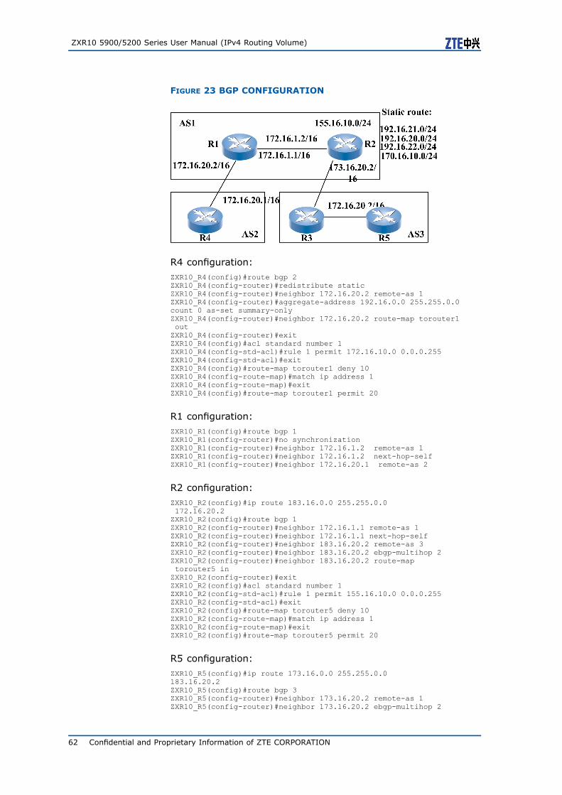
ZXR10 5900/5200 Series User Manual (IPv4 Routing Volume)
FIGURE 23 BGP CONFIGURATION
R4 configuration:ZXR10_R4(config)#route bgp 2ZXR10_R4(config-router)#redistribute staticZXR10_R4(config-router)#neighbor 172.16.20.2 remote-as 1ZXR10_R4(config-router)#aggregate-address 192.16.0.0 255.255.0.0count 0 as-set summary-onlyZXR10_R4(config-router)#neighbor 172.16.20.2 route-map torouter1outZXR10_R4(config-router)#exitZXR10_R4(config)#acl standard number 1ZXR10_R4(config-std-acl)#rule 1 permit 172.16.10.0 0.0.0.255ZXR10_R4(config-std-acl)#exitZXR10_R4(config)#route-map torouter1 deny 10ZXR10_R4(config-route-map)#match ip address 1ZXR10_R4(config-route-map)#exitZXR10_R4(config)#route-map torouter1 permit 20
R1 configuration:ZXR10_R1(config)#route bgp 1ZXR10_R1(config-router)#no synchronizationZXR10_R1(config-router)#neighbor 172.16.1.2 remote-as 1ZXR10_R1(config-router)#neighbor 172.16.1.2 next-hop-selfZXR10_R1(config-router)#neighbor 172.16.20.1 remote-as 2
R2 configuration:ZXR10_R2(config)#ip route 183.16.0.0 255.255.0.0172.16.20.2ZXR10_R2(config)#route bgp 1ZXR10_R2(config-router)#neighbor 172.16.1.1 remote-as 1ZXR10_R2(config-router)#neighbor 172.16.1.1 next-hop-selfZXR10_R2(config-router)#neighbor 183.16.20.2 remote-as 3ZXR10_R2(config-router)#neighbor 183.16.20.2 ebgp-multihop 2ZXR10_R2(config-router)#neighbor 183.16.20.2 route-maptorouter5 inZXR10_R2(config-router)#exitZXR10_R2(config)#acl standard number 1ZXR10_R2(config-std-acl)#rule 1 permit 155.16.10.0 0.0.0.255ZXR10_R2(config-std-acl)#exitZXR10_R2(config)#route-map torouter5 deny 10ZXR10_R2(config-route-map)#match ip address 1ZXR10_R2(config-route-map)#exitZXR10_R2(config)#route-map torouter5 permit 20
R5 configuration:ZXR10_R5(config)#ip route 173.16.0.0 255.255.0.0183.16.20.2ZXR10_R5(config)#route bgp 3ZXR10_R5(config-router)#neighbor 173.16.20.2 remote-as 1ZXR10_R5(config-router)#neighbor 173.16.20.2 ebgp-multihop 2
62 Confidential and Proprietary Information of ZTE CORPORATION

Chapter 5 BGP Configuration
BGP Maintenance andDiagnosis
Step Command Function
1 ZXR10(config)#show ip bgp protocol This displays the configurationinformation of the BGPmodule.
2 ZXR10(config)#show ip bgp neighbor [in|out]<ip-address>
This displays the BGPadjacency and the currentneighbor state.
3 ZXR10(config)#show ip bgp[network <ip-address>[mask <net-mask>]]
This displays the BGP routingtable entries.
4 ZXR10(config)#show ip bgp summary This displays the connectionstate of all BGP neighbors.
5 ZXR10(config)#show ip route [<ip-address><net-mask>] bgp
This displays routing tableand checks if BGP in the routetable.
6 ZXR10(config)#show ip forwarding subnetrt<ip-address><net-mask>
This displays hardware drivingrouting table.
7 ZXR10#debug ip bgp in This traces and show thenotification packet sent bythe BGP.
8 ZXR10#debug ip bgp out This tracks and display thenotification packet sent bythe BGP.
9 ZXR10#debug ip bgp events This traces and display thetransition of state machineconnected to the BGP.
Example This example is to trace the state transition of the BGP with thedebug ip bgp events command.ZXR10#debug ip bgp eventsBGP events debugging is onZXR10#04:10:07: BGP: 192.168.1.2 reset due to Erroneous BGPOpen received04:10:07: BGP: 192.168.1.2 went from Connect to Idle04:10:08: BGP: 192.168.1.2 went from Idle to Connect04:10:13: BGP: 192.168.1.2 went from Connect to OpenSent04:10:13: BGP: 192.168.1.2 went from OpenSent to OpenConfirm04:10:13: BGP: 192.168.1.2 went from OpenConfirm toEstablishedZXR10#
Confidential and Proprietary Information of ZTE CORPORATION 63

ZXR10 5900/5200 Series User Manual (IPv4 Routing Volume)
This page is intentionally blank.
64 Confidential and Proprietary Information of ZTE CORPORATION

C h a p t e r 6
Multicast RoutingConfiguration
Table of ContentsMulticast Overview ............................................................65Configuring Public Multicast ................................................69Configuring IGMP Version ...................................................69Configuring PIM-SM ...........................................................72Configuring MSDP..............................................................76Configuring PIM-DM...........................................................78Configuring PIM-SNOOPING ................................................78Multicast Configuration Example ..........................................78Multicast Maintenance and Diagnosis....................................80
Multicast OverviewMulticast is a point-to-multipoint or multipoint-to-multipoint com-munication mode. Multiple receivers can synchronously receivethe same message from one source. The applications based onmulticast include video conference, distance learning and softwaredistribution.
Multicast protocol consists of the group member management pro-tocol and the multicast routing protocol. The group member man-agement protocol is applicable to management of the joining orleaving of multicast group members. Multicast routing protocol isresponsible for the establishment of a multicast tree by exchang-ing information between routers. Multicast routing protocol canbe divided into the intra-area multicast routing protocol and theinter-area multicast routing protocol.
ZXR10 5900/5200 supports the following protocols:
� IGMPInternet Group Management Protocol
� PIM-SMProtocol Independent Multicast Sparse Mode
� MSDPMulticast Source Discovery Protocol
� PIM-DMProtocol Independent Multicast Dense Mode
Confidential and Proprietary Information of ZTE CORPORATION 65
ZXR10 5900/5200 Series User Manual (IPv4 Routing Volume)
Multicast Address
In a multicast network the sender sends a packet to multiplereceivers in a multicast mode. In this situation the sender iscalled the multicast source. Multiple receivers for the same packetare identified by same ID. This is called the multicast groupaddress. In the IP address allocation scheme class D IP addressis 224.0.0.0-239.255.255.255. It is just a multicast address.224.0.0.0-224.0.0.255 and 239.0.0.0-239.255.255.255 are usedfor the purpose of research and management.
IGMP
IGMP is a protocol that is used to help the multicast router to getinformation of multicast group members which are running be-tween mainframe and multicast router.
Multicast router periodically sends query messages of group mem-bers to all mainframes in order to know which specific group mem-bers exist in the connected networks. The mainframe returns areport message of group members, reporting the multicast groupwhich they belong to. A mainframe immediately sends report mes-sages of group members instead of awaiting a query when it joinsa new group.
When the mainframe leaves the group, it sends a message indi-cating its purpose to the multicast router. The multicast router willimmediately query whether there are still group members runningin the group. If so, the multicast router will continue to forwarddata. If not, it will not forward data any longer.
In the current actual applications there are two versions: IGMP V1and IGMP V2.
IGMP V2 has more enhanced features than the IGMP V1. It finishesexchanging information between the mainframe and the routers bymeans of four types of messages.
1. Group member query2. V2 member report3. Leave report4. V1 member report
V1 member report is used for the compatibility with the IGMP V1.
Multicast Tree
In a multicast communication router the possession of multicastsource, receiver and of multicast packet path is essential. For pathselection, the most common method is to construct tree routes.Tree route has the following two advantages:
1. The packet reaches different receivers along branches in a par-allel mode.
66 Confidential and Proprietary Information of ZTE CORPORATION
Chapter 6 Multicast Routing Configuration
2. The packet copy only occurs in the branch position whichmakes the sent packets over network minimum.
A multicast tree is a set, which is composed of a series of in-put interfaces and output interfaces of routes. It determines onlyone forwarding path between both the subnet where the multicastsource lies and the subnets containing group members.
There are two basic methods to construct multicast trees: thesource-based multicast tree and the multicast rendezvous pointtree (RPT).
1. Source-Based Multicast Tree
The source-based multicast tree is also called source shortestpath tree. It constructs a spanning tree toward all receivers foreach source. The spanning tree with the subnet of the sourceas a root node extends to the subnet where receivers exist. Amulticast group may have multiple multicast sources.
Each source or each pair (S, G) has a corresponding multicasttree.
Method to construct the source-based multicast trees is the re-verse path forwarding (RPF). Each router can find the shortestpath toward the source and the corresponding output inter-face according to a unicast route. When receiving a multicastpacket, a router checks whether the input interface receiving itis the output interface of the shortest unicast path toward thesource itself. If so, the router copies and forwards the packetto other interfaces. If not, the router discards the multicastpacket.
The input interface receiving the multicast packet in the routeris called the father link. The output interface sending the mul-ticast packet is called the sub-link.
2. Multicast Rendezvous Point Tree
The multicast rendezvous point tree constructs a multicast treefor each multicast group. This tree is shared by all members.Namely, the (*, G) use commonly a preceding multicast treebut not construct a tree for each pair (S, G). Each device want-ing to receive the multicast packet of the group must explicitlyjoin the RPT.
The multicast RPT uses a router or a group of routers as thecenter of the multicast tree. All source direction receivers sendthe packet to the center in a unicast mode, and start to forwardfrom the center along the multicast RPT tree in a multicastmode.
PIM-SM
PIM-SM sends multicast packet by using the multicast RPT. A mul-ticast RPT has a center point that is responsible for sending packetsto the ports of all sources of a multicast group. Send ports of eachsource sends packets to the center point along the shortest pathand distribute packets to receiving ports. The group center pointof the PIM-SM is called Rendezvous Point (RP). A network mayhave multiple RPs, whereas a multicast group has only one RP.
Confidential and Proprietary Information of ZTE CORPORATION 67

ZXR10 5900/5200 Series User Manual (IPv4 Routing Volume)
A router can determine the location of the RP by three methods.The first method is the manual static configuration RP runningrouters of the PIM-SM. The other two methods are dynamic. Theyare determined according to the PIM-SM version adopted by thenetwork. The PIM-SM V 1 adopts the Auto-RP whereas PIM-SM V2adopts Candidate-RP advertising mode. The Candidate-RP withhigher priority is the formal RP.
PIM-SM V2 manually configures some routers running PIM-SM asCandidate-BSR (BootStrap Router) and selects the Candidate-BSRas the formal BSR. The BSR is responsible for collecting Candi-date-RP information of multicast routers. If finding some Candi-date-RP, the BSR advertises them to all PIM routers in the PIMarea. These PIM routers according to the similar Hash rules selectone with higher priority as the formal RP from the same candi-date-RP set. The candidate-RP is manually configured.
The routers running PIM-SM find them and maintain the adjacencyby exchanging the Hello messages. In the Multi-access networkthe Hello message also contains the priority information of therouter. According to the parameter, select the Designate Router(DR).
Multicast source or the first hop router (DR directly connected withthe source) encapsulates the packet in a registration message andsends it to the RP through the unicast router. When receiving theregistration message the RP decapsulates and takes out the packetand sends it to the receiver of the group along the RPT.
Each mainframe acting as the receiver joins the multicast groupthrough the member report message of the IGMP. The last hoprouter (or the DR in the multi-access network) sends the receivedjoining message to the RP for registration level by level. Interme-diary router checks whether to have the router of the group afterreceiving the joining message. If so, the intermediary router addsthe request router of the downstream to the RPT as a branch. Ifnot, it continues to send the joining message to the RP.
When the RP or the multicast router is directly connected with thereceiver they can switch to the source-based shortest path treefrom the RPT. When the RP receives registration messages sentfrom a new multicast source, the RP returns a joining messageto the DR directly connected with the multicast source. Thus, theshortest path tree from the source to the RP is established.
A DR or router directly connected with the multicast membersreceives the first multicast packet from the multicast or the re-ceived packet reaches a threshold. They can switch to the source-based shortest path tree from the RPT. Once switchover occurs,the router will send a prune message to the neighbor of the up-stream and require leaving the RPT.
MSDP
MSDP is a mechanism that allows RPs in each PIM-SM domain toshare information about active sources. Each RP knows the re-ceivers within the local domain. When RPs has learned informa-tion about active sources in remote domains, they can transfer theinformation to receivers in local domain. Thus, multicast packetscan be forwarded among domains.
68 Confidential and Proprietary Information of ZTE CORPORATION

Chapter 6 Multicast Routing Configuration
MSDP speaker in a PIM-SM domain establishes MSDP peering ses-sion with MSDP peers in other domains through TCP connection.When MSDP speaker has learnt a new multicast source (throughthe PIM register mechanism) in local domain, it creates a Source-Active message and sends it to all the MSDP peers.
Each MSDP peer that receives the message uses peer-RPF checkand only the SA message received on correct interface is for-warded, discarding the others. When an MSDP peer which is alsoan RP for its own domain receives a new SA message and theoutgoing interface list in (*, G) entry is non-empty, that is, thereare receivers within the domain, RP creates a (S, G) state formulticast source and adds this entry to the shortest-path tree ofthe source.
In addition, each MSDP peer saves the received SA messages in acache, thus establishing a SA cache table. If the RP in a PIM-SMdomain receives a new PIM join message for multicast group G,the RP searches its own SA cache table to get all the active mul-ticast sources immediately, thus generating the corresponding (S,G) Join message.
PIM-SNOOPING
PIM Snooping obtains the multicast routing port by snooping theHELLO and JOIN/PRUNE messages of the multicast protocol andforwards the multicast data as well as reduces network traffic.
Configuring Public MulticastStep Command Function
1 ZXR10(config)#ip multicast-routing This boots the IP multicastroute.
2 ZXR10#clear ip mroute [group-address <group-address>][source-address <source-address>]
This deletes the IP multicastrouting table.
Configuring IGMP VersionZXR10 5900/5200 IGMP function is based on PIM interface. Allinterfaces enabling PIM enables IGMP function automatically.
Configuring IGMP Version
At present the IGMP has the V1 and the V2. Default value is V2.For security, a router requires router requires the Network Element
Confidential and Proprietary Information of ZTE CORPORATION 69

ZXR10 5900/5200 Series User Manual (IPv4 Routing Volume)
(NE) in the same network segment to be the IGMP V1 or the IGMPV2.
For the configuration of IGMP version number of the interface, usethe following command.
Command Function
ZXR10(config-if-vlanX)#ip igmp version <version> This configures IGMP version.
Configuring an IGMP Group
1. To configure group range that allows IGMP to join, use thefollowing command.
Command Function
ZXR10(config-if-vlanX)#ip igmp access-group<acl-number>
This configures group range thatallows IGMP to join.
This example shows running of IGMP on the interface. The in-terface receives all multicast groups by default and sets thereceiving group range on the interface. When the joining re-quest from the mainframe does not belong to the range discardthe joining request.
Only receive the group 239.10.10.10 on the Vlanl interface.ZXR10(config)#acl standard number 10ZXR10(config-std-acl)#rule 1 permit 239.10.10.10 0.0.0.0ZXR10(config-std-acl)#exitZXR10(config)#interface vlan 1ZXR10(config-if-vlan1)#ip igmp access-group 10
2. To configure the group range permitting the IGMP to leave rightaway, use the following command.
Command Function
ZXR10(config-if-vlanX)#ip igmp immediate-leave[group-list <acl-number>]
This configures the group rangepermitting the IGMP to leaveright away.
Upon receiving the message of the IGMP leaving or not re-ceiving the Report message within (last member query inter-valx2+1) seconds then the group members leaves.
In the below configuration the group is permitted 239.10.10.10to leave right away on the Vlanl interface.ZXR10(config)#acl standard number 10ZXR10(config-std-acl)#rule 1 permit 239.10.10.10 0.0.0.0ZXR10(config-std-acl)#exitZXR10(config)#interface vlan 1ZXR10(config-if-vlan1)#ip igmp immediate-leave group-list 10
3. To configure the static group member on the IGMP interface,use the following command.
70 Confidential and Proprietary Information of ZTE CORPORATION

Chapter 6 Multicast Routing Configuration
Command Function
ZXR10(config-if-vlanX)#ip igmp static-group<group-address>
This configures the static groupmember on the IGMP interface.
Above configuration statically binds the group address to aninterface. Supposing there are always members of the groupon the interface.
To configure the static group 239.10.10.10 on the Vlanl inter-face is shown below:ZXR10(config)#interface vlan 1ZXR10(config-if-vlan1)#ip igmp static-group 239.10.10.10
Configuring IGMP Timer
IGMP boots on the multicast router interface that is connected witha shared network segment. Select the optimum one as the Querierof the network segment which is responsible for sending the querymessage to obtain the information of the group members.
After sending query messages, the Querier will wait for the mem-ber report of the receiving mainframe for some time. The durationis the Max Response Time value carried when sending query mes-sages. The default value is 10 seconds.
Upon receiving query messages the mainframe member on thenetwork segment will reduce a random deviation value based onthe maximum response time. It will take the result as its ownresponse time.
During this period the mainframe member will cancel the receivingreports of other mainframe. If the mainframe report is not can-celled then mainframe member will send the mainframe report atthe right time. Therefore, prolonging the max response time willaccordingly increase the waiting chances for the group memberof the network segment. The mainframe member will reduce theburst rate of multiple mainframe reports on the network segment.
Step Command Function
1 ZXR10(config-if-vlanX)#ip igmp query-interval<seconds>
This configures IGMP querytime interval.
2 ZXR10(config-if-vlanX)#ip igmp querier-timeout<seconds>
This configures the IGMPquerier timeout length.
3 ZXR10(config-if-vlanX)#ip igmp query-max-response-time<seconds>
This configures the maximumresponse time value carriedby query messages when theIGMP sends query messages.
4 ZXR10(config-if-vlanX)#ip igmp last-member-query-interval<seconds>
This configures the queryinterval of a specific group ofthe IGMP.
Confidential and Proprietary Information of ZTE CORPORATION 71
ZXR10 5900/5200 Series User Manual (IPv4 Routing Volume)
Configuring ssm-mapping
To configure ssm-mapping and take received igmp v2 user as v3user, use the following command.
Step Command Function
1 ZXR10(config)#ip igmp snooping ssm-mapping This enables ssm-mappingfunction globally.
2 ZXR10(config)#ip igmp snooping ssm-mapping-rule<group address><source address>
This configures ssm-mappingrule.
3 ZXR10(config)#ip igmp snooping clear-ssm-mapping This clears all configuredssm-mapping rules.
Configuring PIM-SMBooting PIM-SM
Command Function
ZXR10(config)#router pimsm This boots PIM-SM.
Configuring Static RP Address
Configuration should be done of a static RP for a multiple specificgroups and also configure same static RPs for the group on allPIM-SM multicast routers in the multicast area.
Usually the loopback interface address is used to reduce the net-work vibration caused by the Up/Down of a physical interface.
After the static RP is configured, it is not necessary to configurethe Candidate-RP for the group.
To configure the static RP address, use the following command.
Command Function
ZXR10(config-router)#static-rp <ip-address>[group-list<acl-number>][priority <priority>]
This configures static RPaddress.
Example 1. This example shows configuration of static RP 10.1.1.1 for allgroups.ZXR10(config-router)#static-rp 10.1.1.1
2. Configuration of the static RP 10.1.1.1 for the group239.132.10.100 is shown below.ZXR10(config-router)#static-rp 10.1.1.1 group-list 10ZXR10(config-router)#exit
72 Confidential and Proprietary Information of ZTE CORPORATION

Chapter 6 Multicast Routing Configuration
ZXR10(config)#acl standard number 10ZXR10(config-std-acl)#rule 1 permit 239.132.10.100 0.0.0.0
Configuring Candidate-BSR
If the static RP mechanism is not used then every multicast areamust be configured with the Candidate-BSR on more than one mul-ticast routers. A BSR should be selected. The BSR sends bootingmessages to advertise RP information. According to the latest ad-vertising messages, router running the PIM-SM updates the RPstate. The bootstrap message send by the BSR is also used to se-lect the formal BSR in the Candidate-BSR.
To configure Candidate-BSR, use the following command
Command Function
ZXR10(config-router)#bsr-candidate <interface-name>[<hash-mask-length>][<priority>]
This configures Candidate-BSR.
The default priority of Candidate-BSR is 0. Candidate-BSR withhigher priority becomes formal BSR.
Configure the Candidate-RP
In the PIM-SM, the RP is a root of the multicast RPT. It is respon-sible for sending the multicast packet to the receiving member ofthe group in the downstream along the tree. Each multicast grouphas only one formal RP.
To configure the Candidate-RP, use the following command.
Command Function
ZXR10(config-router)#rp-candidate <interface-name>[group-list <acl-number>][priority <priority>]
This configures theCandidate-RP.
The default priority of the Candidate-RP is 0. The candidate-RPwith greater priority value has smaller priority.
Switching Routers with DirectlyConnected Receivers
Only the last hop DR and the RP can actively switch to the sourceshortest path tree. By default, start to switch the source shortestpath tree when the RP receives the first registration information.For the last hop DR, configure the switch threshold strategy of thesource shortest path tree, with the unicast group as control gran-
Confidential and Proprietary Information of ZTE CORPORATION 73

ZXR10 5900/5200 Series User Manual (IPv4 Routing Volume)
ularity. If configuring the switch threshold with infinity, switchingdoes not occur. By default, switch must take place if traffic exists.
Command Function
ZXR10(config-router)#spt-threshold infinity [group-list<access-list-number>]
This switches routers withdirectly connected receiversfrom SPT tree to the RPT
Configuring the Area Border with theInterface PIM
Command Function
ZXR10(config-if-vlanX)#ip pim bsr-border This configures the area borderwith the interface PIM.
Bootstrap data packets cannot pass the border in any direction.The command effectively divides a network into different BSR ar-eas. Other PIM packets can pass the area border.
Setting the RP to Filter the ReceivedRegister Packet
Command Function
ZXR10(config-router)#accept-register<acl-number> This sets the RP to filter thereceived Register packet.
Limiting the BSR Message toAdvertise to the Candidate-RP
To limit the BSR message to advertise to the Candidate-RP, usethe following command
Command Function
ZXR10(config-router)#accept-rp <acl-number> This limits the BSR message toadvertise to the Candidate-RP.
74 Confidential and Proprietary Information of ZTE CORPORATION

Chapter 6 Multicast Routing Configuration
Setting DR Priority
Command Function
ZXR10(config-if-vlanX)#ip pim dr-priority<priority> This sets the DR priority.
It is necessary to select a DR in a shared (or Multi-Access) networksegment. Router with the highest priority will win the selection. Ifthe priorities are similar, the router with the greatest IP addresswill be selected.
In the shared network segment connected with the multicast datasource only the DR can send the registration information to the RP.In the shared network segment connected with the receiver onlythe DR can respond to the joining and leaving messages of theIGMP and sends the PIM joining/prune message to the upstream.
The priority of the router is contained in the exchanging Hello mes-sage with the neighbor. The default value is 0.
Setting the Sending Interval of theHello Message
Command Function
ZXR10(config-if-vlanX)#ip pim query-interval <seconds> This sets the sending interval ofthe Hello message.
Limiting PIM-SM Neighbor
Command Function
ZXR10(config-if-vlanX)#ip pim neighbor-filter<acl-number>
This limits some routers to bePIM neighbor.
Example This example shows that the router 10.1.1.1 is limited to be thePIM neighbors on the interface Vlan1.ZXR10(config)#acl standard number 10ZXR10(config-std-acl)#rule 1 deny 10.1.1.1 0.0.0.0ZXR10(config-std-acl)#rule 2 permit anyZXR10(config-router)#exitZXR10(config)#interface vlan 1ZXR10(config-if-vlan1)#ip pim neighbor-filter 10
Confidential and Proprietary Information of ZTE CORPORATION 75

ZXR10 5900/5200 Series User Manual (IPv4 Routing Volume)
Configuring MSDPEnabling MSDP
Command Function
ZXR10(config)#ip msdp peer <peer-address>connect-source <interface-name>
This configures an MSDP peerand enables MSDP.
Configuring Default MSDP Peer
Command Function
ZXR10(config)#ip msdp default-peer <peer-address>[list<acl-number>]
This configures default MSDPpeer.
When default MSDP peer is configured, the local router accepts allSA messages from the peer.
Configuring an Originating RP
Command Function
ZXR10(config)#ip msdp originator-id <interface-name> This configures an originatingRP.
This command generates the MSDP speaker of SA messages. Italso uses address of specified interface as the RP address in a SA.
Configuring the MSDP Peer as aMesh Group Member
Command Function
ZXR10(config)#ip msdp mesh-group <peer-address><mesh-name>
This configures the MSDP peeras a mesh group member.
A "mesh group" is a group of MSDP speakers. These speakershave fully meshed connectivity.
76 Confidential and Proprietary Information of ZTE CORPORATION
Chapter 6 Multicast Routing Configuration
Clearing Statistics Counter for MSDPPeers
Command Function
ZXR10#clear ip msdp statistics [<peer-address>] This clears statistics counter forMSDP peers.
Clearing Statistics Counter for MSDPPeers
Command Function
ZXR10#clear ip msdp statistics [<peer-address>] This clears statistics counter forMSDP peers.
Clearing Statistics Counter for MSDPPeers
Command Function
ZXR10#clear ip msdp statistics [<peer-address>] This clears statistics counter forMSDP peers.
Clearing Statistics Counter for MSDPPeers
Command Function
ZXR10#clear ip msdp statistics [<peer-address>] This clears statistics counter forMSDP peers.
Confidential and Proprietary Information of ZTE CORPORATION 77

ZXR10 5900/5200 Series User Manual (IPv4 Routing Volume)
Clearing Statistics Counter for MSDPPeers
Command Function
ZXR10#clear ip msdp statistics [<peer-address>] This clears statistics counter forMSDP peers.
Configuring PIM-DMStep Command Function
1 ZXR10(config)#router pimdm This enables PIM-DM function.
2 ZXR10(config-if)#ip pim dm This adds an interface thatruns PIM-DM.
Configuring PIM-SNOOPING
Step Command Function
1 ZXR10(config)#ip pim snooping This enables PIM-SNOOPINGfunction.
2 ZXR10(config-vlanX)#pim snooping This enables PIM-SNOOPINGfunction in VLAN.
Multicast ConfigurationExamplePIM-SM configuration and network topology is shown in Figure 24.
78 Confidential and Proprietary Information of ZTE CORPORATION

Chapter 6 Multicast Routing Configuration
FIGURE 24 MULTICAST CONFIGURATION
R1 configuration:ZXR10_R1(config)#ip multicast-routingZXR10_R1(config)#interface loopback1ZXR10_R1(config-loopback1)#ip address 10.1.1.1 255.255.255.255ZXR10_R1(config)#router pimsmZXR10_R1(config-router)#rp-candidate loopback1 priority 10ZXR10_R1(config-router)#bsr-candidate loopback1 10 10ZXR10_R1(config)#interface vlan1ZXR10_R1(config-if-vlan1)#ip address 10.10.10.1 255.255.255.0ZXR10_R1(config-if-vlan1)#ip pim smZXR10_R1(config)#interface vlan2ZXR10_R1(config-if-vlan2)#ip address 10.10.20.1 255.255.255.0ZXR10_R1(config-if-vlan2)#ip pim smZXR10_R1(config)#interface vlan3ZXR10_R1(config-if-vlan3)#ip address 10.10.30.1 255.255.255.0ZXR10_R1(config-if-vlan3)#ip pim smZXR10_R1(config)#router ospf 1ZXR10_R1(config-router)#network 10.0.0.0 0.0.0.255 area 0.0.0.0
R2 configuration:ZXR10_R2(config)#ip multicast-routingZXR10_R2(config)#interface loopback1ZXR10_R2(config-loopback1)#ip address 10.1.1.2 255.255.255.255ZXR10_R2(config)#router pimsmZXR10_R2(config-router)#rp-candidate loopback1 priority 20ZXR10_R2(config-router)#bsr-candidate loopback1 10 20ZXR10_R2(config)#interface vlan1ZXR10_R2(config-if-vlan1)#ip address 10.10.20.2 255.255.255.0ZXR10_R2(config-if-vlan1)#ip pim smZXR10_R2(config)#interface vlan2ZXR10_R2(config-if-vlan2)#ip address 10.10.40.1 255.255.255.0ZXR10_R2(config-if-vlan2)#ip pim smZXR10_R2(config)#interface vlan3ZXR10_R2(config-if-vlan3)#ip address 10.10.50.1 255.255.255.0ZXR10_R2(config-if-vlan3)#ip igmp access-group 10ZXR10_R2(config)#router ospf 1ZXR10_R2(config-router)#network 10.0.0.0 0.0.0.255 area 0.0.0.0
R3 configuration:ZXR10_R3(config)#ip multicast-routingZXR10_R3(config)#interface loopback1ZXR10_R3(config-loopback1)#ip address 10.1.1.3 255.255.255.255ZXR10_R3(config)#router pimsm
Confidential and Proprietary Information of ZTE CORPORATION 79

ZXR10 5900/5200 Series User Manual (IPv4 Routing Volume)
ZXR10_R3(config-router)#rp-candidate loopback1 priority 30ZXR10_R3(config-router)#bsr-candidate loopback1 10 30ZXR10_R3(config)#interface vlan1ZXR10_R3(config-if-vlan1)#ip address 10.10.30.2 255.255.255.0ZXR10_R3(config-if-vlan1)#ip pim smZXR10_R3(config)#interface vlan2ZXR10_R3(config-if-vlan2)#ip address 10.10.40.2 255.255.255.0ZXR10_R3(config-if-vlan2)#ip pim smZXR10_R3(config)#router ospf 1ZXR10_R3(config-router)#network 10.0.0.0 0.0.0.255 area 0.0.0.0
Multicast Maintenance andDiagnosis
Common ViewCommand
1. To view the IP multicast routing table, use the following com-mand.
Command Function
ZXR10#show ip mroute [group <group-address>][source<source-address>][summary]
This views the IP multicastrouting table.
This shows the contents of the current IP multicast routingtable.ZXR10#show ip mrouteIP Multicast Routing TableFlags:D -Dense,S -Sparse,C -Connected,L -Local,P -Pruned
R -RP-bit set,F -Register flag,T -SPT-bit set,J -Join SPT,M - MSDP created entry,N -No Used,U -Up Send,A - Advertised via MSDP,X -Proxy Join Timer Running,* -Assert flag
Statistic:Receive packet count/Send packet countTimers:Uptime/ExpiresInterface state:Interface,Next-Hop or VCD,State/Mode
(*, 229.3.3.16), 00:00:01/00:03:34, RP 5.5.5.6 , 0/0, flags: SPIncoming interface: vlan5, RPF nbr 5.5.5.6Outgoing interface list: NULL
(100.1.1.100, 229.3.3.16), 00:00:01/00:03:34 , 0/0, flags: UNIncoming interface: vlan4, RPF nbr 4.4.4.5Outgoing interface list:vlan6, Forward/Sparse, 00:00:01/00:03:29
2. To show multicast forwarding entries, use the following com-mand.
Command Function
ZXR10#show ip mforwarding [device <device-number>]group-address <group-address>[source-address<source-address>]
This shows multicast forwardingentries. If the commanddoes not carry source addressoptions, show (*, G) multicastforwarding entries. If carryingsource address options, show(S, G) multicast forwardingentries.
80 Confidential and Proprietary Information of ZTE CORPORATION

Chapter 6 Multicast Routing Configuration
This shows the multicast forwarding entries.ZXR10#show ip mforwarding group-address 229.3.3.16IP Forwarding Multicast Routing TableFlags: N -No Used,U -Up Send,L -Limit upSend,A - Assert send
(*, 229.3.3.16), Flags:, HitFlag:0, Incoming interface: Null,LastSrcIp: 0.0.0.0Outgoing vlan interface list: NULL
L2bitmap:0x0000000000000000 L3bitmap:0x0000000000000000
(100.1.1.100, 229.3.3.16), Flags:, HitFlag:0,Incoming interface: vlan4 19/3, LastSrcIp: 0.0.0.0Outgoing vlan interface list: NULL
L2bitmap:0x4000000000000008 L3bitmap:0x0000000000000000
3. To show the multicast reverse path forwarding message, usethe following command.
Command Function
ZXR10(config)#show ip rpf <source-address> This shows the multicast reversepath forwarding message.
4. To view the PIM-SM multicast routing table, use the followingcommand.
Command Function
ZXR10(config)#show ip pimsm mroute [group<group-address>][source <source-address>][summary]
This views the PIM-SM multicastrouting table.
Viewing IGMPInformationCommands
1. To view the IGMP configuration on the interface, use the fol-lowing command.
Command Function
ZXR10#show ip igmp interface[<interface-name>] This views the IGMPconfiguration on the interface.
This shows the IGMP configuration information of the Vlan4interface.ZXR10#show ip igmp interface vlan4vlan4Internet address is 4.4.4.4, subnet mask is 255.255.255.0IGMP is enabled on interfaceCurrent IGMP version is 2IGMP query interval is 125 secondsIGMP last member query interval is 1 secondsIGMP query max response time is 10 secondsIGMP querier timeout period is 251 secondsIGMP querier is 4.4.4.4, never expireInbound IGMP access group is not setIGMP immediate leave control is not set
2. To view the joining information of the IGMP group on the in-terface, use the following command.
Confidential and Proprietary Information of ZTE CORPORATION 81
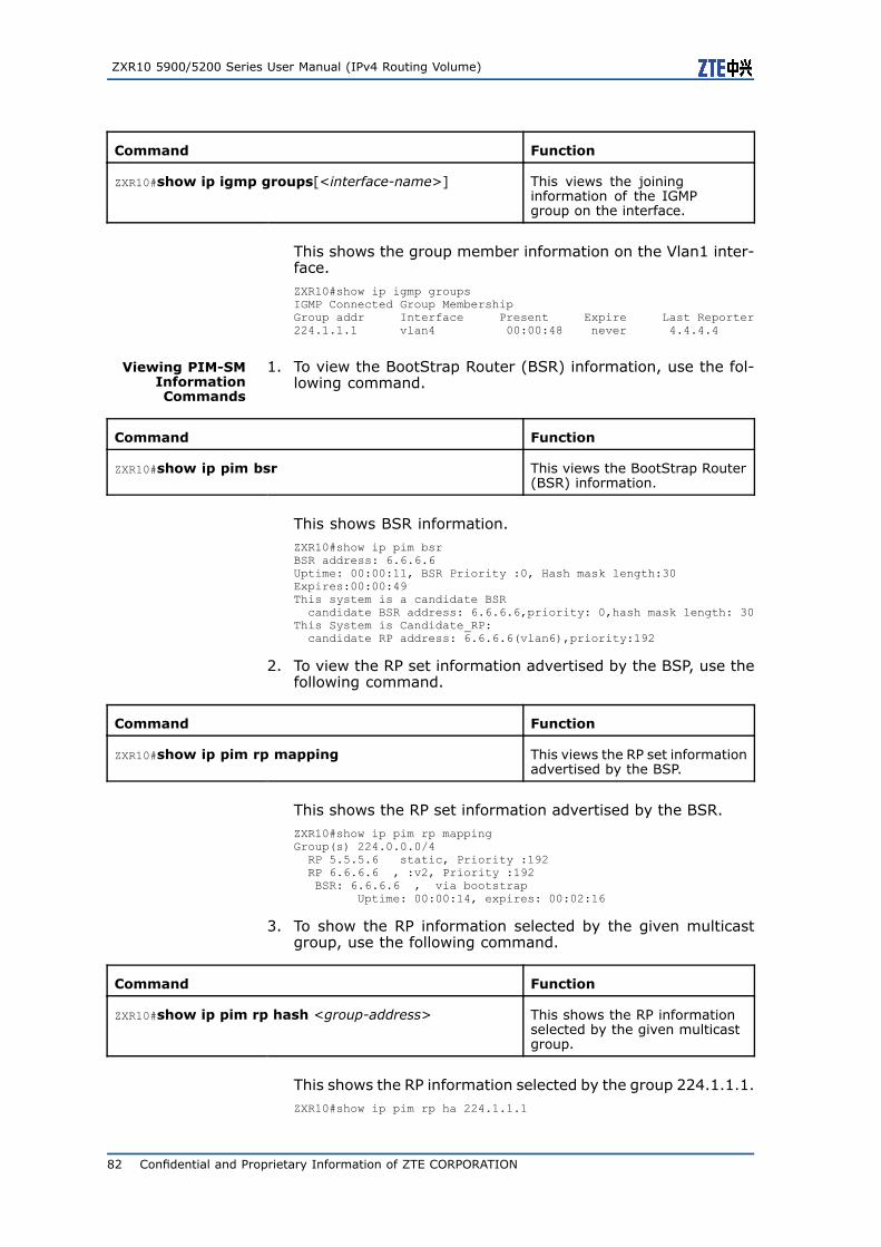
ZXR10 5900/5200 Series User Manual (IPv4 Routing Volume)
Command Function
ZXR10#show ip igmp groups[<interface-name>] This views the joininginformation of the IGMPgroup on the interface.
This shows the group member information on the Vlan1 inter-face.ZXR10#show ip igmp groupsIGMP Connected Group MembershipGroup addr Interface Present Expire Last Reporter224.1.1.1 vlan4 00:00:48 never 4.4.4.4
Viewing PIM-SMInformationCommands
1. To view the BootStrap Router (BSR) information, use the fol-lowing command.
Command Function
ZXR10#show ip pim bsr This views the BootStrap Router(BSR) information.
This shows BSR information.ZXR10#show ip pim bsrBSR address: 6.6.6.6Uptime: 00:00:11, BSR Priority :0, Hash mask length:30Expires:00:00:49This system is a candidate BSRcandidate BSR address: 6.6.6.6,priority: 0,hash mask length: 30
This System is Candidate_RP:candidate RP address: 6.6.6.6(vlan6),priority:192
2. To view the RP set information advertised by the BSP, use thefollowing command.
Command Function
ZXR10#show ip pim rp mapping This views the RP set informationadvertised by the BSP.
This shows the RP set information advertised by the BSR.ZXR10#show ip pim rp mappingGroup(s) 224.0.0.0/4RP 5.5.5.6 static, Priority :192RP 6.6.6.6 , :v2, Priority :192BSR: 6.6.6.6 , via bootstrap
Uptime: 00:00:14, expires: 00:02:16
3. To show the RP information selected by the given multicastgroup, use the following command.
Command Function
ZXR10#show ip pim rp hash <group-address> This shows the RP informationselected by the given multicastgroup.
This shows the RP information selected by the group 224.1.1.1.ZXR10#show ip pim rp ha 224.1.1.1
82 Confidential and Proprietary Information of ZTE CORPORATION
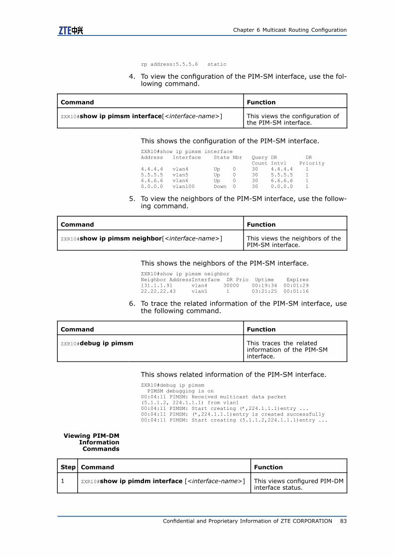
Chapter 6 Multicast Routing Configuration
rp address:5.5.5.6 static
4. To view the configuration of the PIM-SM interface, use the fol-lowing command.
Command Function
ZXR10#show ip pimsm interface[<interface-name>] This views the configuration ofthe PIM-SM interface.
This shows the configuration of the PIM-SM interface.ZXR10#show ip pimsm interfaceAddress Interface State Nbr Query DR DR
Count Intvl Priority4.4.4.4 vlan4 Up 0 30 4.4.4.4 15.5.5.5 vlan5 Up 0 30 5.5.5.5 16.6.6.6 vlan6 Up 0 30 6.6.6.6 10.0.0.0 vlan100 Down 0 30 0.0.0.0 1
5. To view the neighbors of the PIM-SM interface, use the follow-ing command.
Command Function
ZXR10#show ip pimsm neighbor[<interface-name>] This views the neighbors of thePIM-SM interface.
This shows the neighbors of the PIM-SM interface.ZXR10#show ip pimsm neighborNeighbor AddressInterface DR Prio Uptime Expires131.1.1.91 vlan4 30000 00:19:34 00:01:2922.22.22.43 vlan5 1 03:21:25 00:01:16
6. To trace the related information of the PIM-SM interface, usethe following command.
Command Function
ZXR10#debug ip pimsm This traces the relatedinformation of the PIM-SMinterface.
This shows related information of the PIM-SM interface.ZXR10#debug ip pimsmPIMSM debugging is on
00:04:11 PIMSM: Received multicast data packet(5.1.1.2, 224.1.1.1) from vlan100:04:11 PIMSM: Start creating (*,224.1.1.1)entry ...00:04:11 PIMSM: (*,224.1.1.1)entry is created successfully00:04:11 PIMSM: Start creating (5.1.1.2,224.1.1.1)entry ...
Viewing PIM-DMInformationCommands
Step Command Function
1 ZXR10#show ip pimdm interface [<interface-name>] This views configured PIM-DMinterface status.
Confidential and Proprietary Information of ZTE CORPORATION 83

ZXR10 5900/5200 Series User Manual (IPv4 Routing Volume)
Step Command Function
2 ZXR10#show ip pimdm neighbor [<interface-name>] This views PIM-DM interfacestatus.
3 ZXR10#show ip pimdm mroute [[ group<group-address>[ source <source-address>]]|[summary ]]
This views PIM-DM multicastrouting table content.
Parameter Description
group <group-address> multicast group address, in dotted decimal mode
source <source-address> source addressin dotted decimal mode
summary brief
Viewing MSDPCommands
1. To view SA message statistics, use the following command.
Command Function
ZXR10#show ip msdp count This views SA messagestatistics.
2. To view MSDP neighbor detailed information, use the followingcommand.
Command Function
ZXR10#show ip msdp peer [<peer-address>] This views MSDP neighbordetailed information.
This shows MSDP neighbor detailed information.ZXR10(config)#show ip msdp peerMSDP Peer 11.1.1.1Description:Connection status:State: Down, Resets: 0, Connection source: vlan4 (4.4.4.4)Uptime(Downtime): 00:00:04, Messages sent/received: 0/0Connection and counters cleared 00:00:04 ago
SA Filtering:Input (S,G) filter: noneOutput (S,G) filter: none
Peer ttl threshold: 0SAs learned from this peer: 0
3. To view S and G status from each MSDP neighbor, use thefollowing command.
Command Function
ZXR10#show ip msdp sa-cache [<group-address>[<source-address>]]
This views S and G status fromeach MSDP neighbor.
This views S and G status from each MSDP neighbor.ZXR10#show ip msdp sa-cache
84 Confidential and Proprietary Information of ZTE CORPORATION

Chapter 6 Multicast Routing Configuration
MSDP Source-Active Cache - 4 entries(101.101.101.101, 224.1.1.1), RP 49.4.4.4, 00:21:45/ 00:05:57(101.101.101.101, 224.1.1.2), RP 49.4.4.4, 00:21:45/ 00:05:57(101.101.101.101, 226.1.1.1), RP 50.4.4.4, 00:09:04/ 00:04:57(101.101.101.101, 226.1.1.2), RP 50.4.4.4, 00:09:04/ 00:04:57
4. To view MSDP neighbor status, use the following command.
Command Function
ZXR10#show ip msdp summary This views MSDP neighborstatus.
This views MSDP neighbor status.ZXR10#show ip msdp summaryMSDP Peer Status SummaryPeer Address State Uptime/ Reset SA
Downtime Count Count101.1.1.1 Up 1d10h 9 2*102.2.2.2 Up 14:24:00 5 20103.3.3.3 Up 12:36:17 5 10
Confidential and Proprietary Information of ZTE CORPORATION 85

ZXR10 5900/5200 Series User Manual (IPv4 Routing Volume)
This page is intentionally blank.
86 Confidential and Proprietary Information of ZTE CORPORATION

C h a p t e r 7
Load BalanceConfiguration
Table of ContentsLoad Balance Overview ......................................................87Configuring Load Balance ...................................................88Load Balance Configuration Example ....................................88Load Balance Maintenance and Diagnosis..............................91
Load Balance OverviewLoad balance is to forward data traffic through multiple activatedlinks existing between equipment and to fully take use of the band-width of multiple links. Load balance does not mean that data traf-fic on links have same size.
Data traffic covers incoming traffic and outgoing traffic. Incomingand outgoing traffic load balance is closely related to the route an-nounced outside and learned by the equipment. Incoming trafficload balance is affected by internal route announced outside by theequipment and outgoing traffic load balance is affected by routeannounced inside by the equipment. They directly affect the in-stallation of multiple route entries reaching the destination in theequipment forwarding table and the control of multiple routes.
ZXR10 5900/5200 adopts route-based load balance to install mul-tiple reachable route entries for a destination address in the for-warding table through configuring the static route, routing protocoland number of routes, thus laying foundation for load balance im-plementation.
ZXR10 5900/5200 supports per-destination load balance policy.This policy considers the source addresses and destination ad-dresses of packets at the same time and make the packets withthe same “source address-destination address” pair pass throughthe same path (even there are multiple available paths), and thepackets with different “source address-destination address” pairspass through different paths. Such a policy ensures the packetswith the same “source address-destination address” pair to arrivein order. Load balance becomes more effective if there are multi-ple “source address-destination address” pairs in traffic.
Eight different paths can arrive at the destination at most in theZXR10 5900/5200. Once load balance is configured, interface traf-fic becomes balanced after a period.
Confidential and Proprietary Information of ZTE CORPORATION 87

ZXR10 5900/5200 Series User Manual (IPv4 Routing Volume)
Configuring Load BalanceStep Command Function
1 ZXR10(config-router)#maximum-paths {<number>|ibgp<number>}
This configures the maximumnumber of routers. Thisconfigures the maximumcount of routes in the RIP,OSPF, IS-IS and BGP routeconfiguration mode. Thedefault number of route is 1and the maximum count is 8.
2 ZXR10(config)#ip route <prefix><net-mask>{<forwarding-router’s-address>|<interface-name>}[<distance-metric>][tag <tag>]
This configures the loadbalance of static route.This configures multiple staticroutes to the same destinationand supports at most eightroutes with different tags.The default value of the tagis 3.
Load Balance ConfigurationExampleR1 is connected to R2 over seven links. This is shown in Figure 25.
FIGURE 25 LOAD BALANCE CONFIGURATION
Static route and dynamic route protocol OSPF is taken as an ex-ample to describe load balance configuration.
Static Routing Load Balance
R1 configuration:
88 Confidential and Proprietary Information of ZTE CORPORATION

Chapter 7 Load Balance Configuration
ZXR10_R1(config)#interface vlan 1ZXR10_R1(config-if-vlan1)#ip address 101.1.1.1 255.255.255.252ZXR10_R1(config)#interface vlan 2ZXR10_R1(config-if-vlan2)#ip address 102.1.1.1 255.255.255.252ZXR10_R1(config)#interface vlan 3ZXR10_R1(config-if-vlan3)#ip address 103.1.1.1 255.255.255.252ZXR10_R1(config)#interface vlan 4ZXR10_R1(config-if-vlan4)#ip address 104.1.1.1 255.255.255.252ZXR10_R1(config)#interface vlan 5ZXR10_R1(config-if-vlan5)#ip address 105.1.1.1 255.255.255.252ZXR10_R1(config)#interface vlan 6ZXR10_R1(config-if-vlan6)#ip address 106.1.1.1 255.255.255.252ZXR10_R1(config)#interface vlan 7ZXR10_R1(config-if-vlan7)#ip address 107.1.1.1 255.255.255.252ZXR10_R1(config)#interface vlan 8ZXR10_R1(config-if-vlan8)#ip address 10.1.1.1 255.255.255.0
ZXR10_R1(config)#ip route 20.1.1.0 255.255.255.0 107.1.1.2 1tag 157ZXR10_R1(config)#ip route 20.1.1.0 255.255.255.0 106.1.1.2 1tag 156ZXR10_R1(config)#ip route 20.1.1.0 255.255.255.0 105.1.1.2 1tag 155ZXR10_R1(config)#ip route 20.1.1.0 255.255.255.0 104.1.1.2 1tag 154ZXR10_R1(config)#ip route 20.1.1.0 255.255.255.0 103.1.1.2 1tag 153ZXR10_R1(config)#ip route 20.1.1.0 255.255.255.0 102.1.1.2 1tag 152ZXR10_R1(config)#ip route 20.1.1.0 255.255.255.0 101.1.1.2 1tag 151
R2 configuration:ZXR10_R2(config)#interface vlan 1ZXR10_R2(config-if-vlan1)#ip address 101.1.1.2 255.255.255.252ZXR10_R2(config)#interface vlan 2ZXR10_R2(config-if-vlan2)#ip address 102.1.1.2 255.255.255.252ZXR10_R2(config)#interface vlan 3ZXR10_R2(config-if-vlan3)#ip address 103.1.1.2 255.255.255.252ZXR10_R2(config)#interface vlan 4ZXR10_R2(config-if-vlan4)#ip address 104.1.1.2 255.255.255.252ZXR10_R2(config)#interface vlan 5ZXR10_R2(config-if-vlan5)#ip address 105.1.1.2 255.255.255.252ZXR10_R2(config)#interface vlan 6ZXR10_R2(config-if-vlan6)#ip address 106.1.1.2 255.255.255.252ZXR10_R2(config)#interface vlan 7ZXR10_R2(config-if-vlan7)#ip address 107.1.1.3 255.255.255.252ZXR10_R2(config)#interface vlan 8ZXR10_R2(config-if-vlan8)#ip address 20.1.1.1 255.255.255.0
ZXR10_R2(config)#ip route 10.1.1.0 255.255.255.0 107.1.1.1 1tag 157ZXR10_R2(config)#ip route 10.1.1.0 255.255.255.0 106.1.1.1 1tag 156ZXR10_R2(config)#ip route 10.1.1.0 255.255.255.0 105.1.1.1 1tag 155ZXR10_R2(config)#ip route 10.1.1.0 255.255.255.0 104.1.1.1 1tag 154ZXR10_R2(config)#ip route 10.1.1.0 255.255.255.0 103.1.1.1 1tag 153ZXR10_R2(config)#ip route 10.1.1.0 255.255.255.0 102.1.1.1 1tag 152ZXR10_R2(config)#ip route 10.1.1.0 255.255.255.0 101.1.1.1 1tag 151
Seven links between R1 and R2 implement load balance and overthese links, the user PC1 and the user PC2 can access each other.
Confidential and Proprietary Information of ZTE CORPORATION 89

ZXR10 5900/5200 Series User Manual (IPv4 Routing Volume)
OSPF Load Balance
R1 configuration:ZXR10_R1(config)#router ospf 100ZXR10_R1(config-router)#network 101.1.1.0 0.0.0.3 area 0.0.0.0ZXR10_R1(config-router)#network 102.1.1.0 0.0.0.3 area 0.0.0.0ZXR10_R1(config-router)#network 103.1.1.0 0.0.0.3 area 0.0.0.0ZXR10_R1(config-router)#network 104.1.1.0 0.0.0.3 area 0.0.0.0ZXR10_R1(config-router)#network 105.1.1.0 0.0.0.3 area 0.0.0.0ZXR10_R1(config-router)#network 106.1.1.0 0.0.0.3 area 0.0.0.0ZXR10_R1(config-router)#network 107.1.1.0 0.0.0.3 area 0.0.0.0ZXR10_R1(config-router)#network 10.1.1.0 0.0.0.255 area 0.0.0.0ZXR10_R1(config-router)#maximum-paths 7
R2 configuration:ZXR10_R2(config)#router ospf 100ZXR10_R2(config-router)#network 101.1.1.0 0.0.0.3 area 0.0.0.0ZXR10_R2(config-router)#network 102.1.1.0 0.0.0.3 area 0.0.0.0ZXR10_R2(config-router)#network 103.1.1.0 0.0.0.3 area 0.0.0.0ZXR10_R2(config-router)#network 104.1.1.0 0.0.0.3 area 0.0.0.0ZXR10_R2(config-router)#network 105.1.1.0 0.0.0.3 area 0.0.0.0ZXR10_R2(config-router)#network 106.1.1.0 0.0.0.3 area 0.0.0.0ZXR10_R2(config-router)#network 107.1.1.0 0.0.0.3 area 0.0.0.0ZXR10_R2(config-router)#network 20.1.1.0 0.0.0.255 area 0.0.0.0ZXR10_R2(config-router)#maximum-paths 7
BGP Load Balance
R1 configuration:ZXR10_R1(config)#router bgp 100ZXR10_R1(config-router)# neighbor 101.1.1.2 remote-as 200ZXR10_R1(config-router)# neighbor 102.1.1.2 remote-as 200ZXR10_R1(config-router)# neighbor 103.1.1.2 remote-as 200ZXR10_R1(config-router)# neighbor 104.1.1.2 remote-as 200ZXR10_R1(config-router)# neighbor 105.1.1.2 remote-as 200ZXR10_R1(config-router)# neighbor 106.1.1.2 remote-as 200ZXR10_R1(config-router)# neighbor 107.1.1.2 remote-as 200ZXR10_R1(config-router)#network 10.1.1.0 255.255.255.0ZXR10_R1(config-router)#maximum-paths 7
R2 configuration:ZXR10_R2(config)#router bgp 200ZXR10_R2(config-router)# neighbor 101.1.1.1 remote-as 100ZXR10_R2(config-router)# neighbor 102.1.1.1 remote-as 100ZXR10_R2(config-router)# neighbor 103.1.1.1 remote-as 100ZXR10_R2(config-router)# neighbor 104.1.1.1 remote-as 100ZXR10_R2(config-router)# neighbor 105.1.1.1 remote-as 100ZXR10_R2(config-router)# neighbor 106.1.1.1 remote-as 100ZXR10_R2(config-router)# neighbor 107.1.1.1 remote-as 100ZXR10_R2(config-router)# network 20.1.1.0 255.255.255.0ZXR10_R2(config-router)#maximum-paths 7
Seven links between R1 and R2 implement load balance and overthese links, the user PC1 and the user PC2 can access each other.
90 Confidential and Proprietary Information of ZTE CORPORATION

Chapter 7 Load Balance Configuration
Load Balance Maintenanceand DiagnosisTo configure load balance maintenance and diagnosis, use the fol-lowing command.
Command Function
ZXR10#show ip route [<ip-address>[<net-mask>]|<protocol>]
This configures load balancemaintenance and diagnosis.
This can be seen that seven paths reaching the destination net-work segment 20.1.1.0/24 on R1 when adopting static route loadbalance:ZXR10_R1#show ip route 20.1.1.0IPv4 Routing Table:Dest Mask Gw Interface Owner pri metric
20.1.1.0 255.255.255.0 107.1.1.1 vlan7 static 1 0
Confidential and Proprietary Information of ZTE CORPORATION 91

ZXR10 5900/5200 Series User Manual (IPv4 Routing Volume)
This page is intentionally blank.
92 Confidential and Proprietary Information of ZTE CORPORATION

Figures
Figure 1 STATIC ROUTE CONFIGURATION .............................. 2
Figure 2 STATIC ROUTE SUMMARY........................................ 3
Figure 3 DEFAULT ROUTE CONFIGURATION............................ 4
Figure 4 BASIC RIP CONFIGURATION ...................................11
Figure 5 OSPF ROUTER TYPES .............................................17
Figure 6 BASIC OSPF CONFIGURATION.................................23
Figure 7 MULTI-AREA OSPF CONFIGURATION ........................24
Figure 8 OSPF VIRTUAL LINK ..............................................26
Figure 9 OSPF AUTHENTICATION .........................................27
Figure 10 IS-IS AREAS.......................................................35
Figure 11 SINGLE AREA CONFIGURATION .............................38
Figure 12 MULTIPLE AREA IS-IS CONFIGURATION..................40
Figure 13 BASIC BGP CONFIGURATION ................................47
Figure 14 BGP ROUTE ADVERTISEMENT................................48
Figure 15 BGP AGGREGATE ADVERTISEMENT ........................49
Figure 16 CONFIGURATION OF BGP MULTIHOP ......................50
Figure 17 FILTERING ROUTES USING NLRI............................52
Figure 18 LOCAL_PREF ATTRIBUTE ......................................53
Figure 19 MED ATTRIBUTE ..................................................55
Figure 20 BGP SYNCHRONIZATION CONFIGURATION..............57
Figure 21 BGP ROUTER REFLECTOR CONFIGURATION.............58
Figure 22 BGP CONFEDERATION CONFIGURATION .................60
Figure 23 BGP CONFIGURATION ..........................................62
Figure 24 MULTICAST CONFIGURATION ................................79
Figure 25 LOAD BALANCE CONFIGURATION ..........................88
Confidential and Proprietary Information of ZTE CORPORATION 93

ZXR10 5900/5200 Series User Manual (IPv4 Routing Volume)
This page is intentionally blank.
94 Confidential and Proprietary Information of ZTE CORPORATION

Tables
Table 1 CHAPTER SUMMARY.................................................. i
Confidential and Proprietary Information of ZTE CORPORATION 95

ZXR10 5900/5200 Series User Manual (IPv4 Routing Volume)
This page is intentionally blank.
96 Confidential and Proprietary Information of ZTE CORPORATION
Glossary
ASBR - Autonomous System Border Router
BDR - Backup Designate Router
ABR - Area Border Router
DIS - Designate IS IS
CLNS - ConnectionLess Network Sevice
CIDR - Classless Inter-Domain Routing
EBGP - External Border Gateway Protocol
DR - Designate Router
ISO - International Organization for Standardization
IGMP - Internet Group Management ProtocolInternet
IGP - Interior Gateway Protocol
LSA - Link State Advertisement
MED - MULTI_EXIT_DISC
NBMA - Non-Broadcast Multiple Access
OSI - Open Systems Interconnection
OSPF - Open Shortest Path First
RIP - Routing Information Protocol
PDU - Protocol Data Unit
SPF - Shortest Path First
VLSM - Variable Length Subnet Mask
SNP - Sequence Num PDU PDU
BSR - Bootstrap Router
IBGP - Interior Border Gateway Protocol
IS-IS - Intermediate System-to-Intermediate System
LSU - Link State Update
MSDP - Multicast Source Discovery Protocol
NSSA - Not-So-Stubby Area
PIM-SM - Protocol Independent Multicast Sparse Mode
RP - Rendezvous Point
AD - Administrative Distance
BGP - Border Gateway Protocol
AS - Autonomous System
Confidential and Proprietary Information of ZTE CORPORATION 97