Embed Size (px)
Citation preview

ALLEVIATION OF ROTOR VIBRATIONS INDUCED BY
DYNAMIC STALL USING ACTIVELY CONTROLLED FLAPS
WITH FREEPLAY
Gilles Depailler [i] and Peretz P. Friedmann [ii]Department of Aerospace Engineering
University of Michigan, Ann Arbor, Michigan
Abstract
This paper presents a successful treatment of thehelicopter vibration reduction problem at high ad-vance ratios, taking into account the effects of dy-namic stall. The ONERA model is used to describethe loads during stall, in conjunction with a rationalfunction approximation for unsteady loads for at-tached flow. This study represents the first success-ful implementation of vibration reduction in pres-ence of dynamic stall, using single and dual trail-ing edge flap confogurations. A physical explana-tion for the vibration reduction process is also pro-vided. Saturation limits on the control deflectionsare imposed, which limit flap deflections to a practi-cal range. Effective vibration reduction is achievedeven when imposing practical saturation limits onthe controller. Finally, the robustness of the vibra-tion reduction process in the presence of a freeplaytype of nonlinearity is also demonstrated.
Notation
a, a0, a2 Separated flow empirical coeffi-cients
b Blade semi chord
Cd0 Blade drag coefficient in attachedflow
cb Blade chord
ccs Flap chord
cwu Multiplier forWu weighting matrix
D Drag force per unit span
D0, D1 Generalized flap motions
[i] Ph. D. Candidate[ii] Francois-Xavier Bagnoud Professor
d Generalized force vector
E,E2 Separated flow empirical coeffi-cients
fCdf Equivalent flat plate fuselage area
h Plunge displacement at the elasticaxis
h Generalized motion vector
Hm Hinge moment around flap hinge
J Objective function
JR Sum of the squares of the trimresiduals
Kδ Spring constant for the freeplaynonlinearity model
L Lift force per unit span
Lcs Control surface length
M Mach number
MAC Pitch moment per unit span hubmoments
Nb Number of blades
p0, p1, pc, ph Functions of M
qb Vector of blade degrees of freedom
qwi, qvi, qφi Participation coefficients in theflap/lead-lag/torsional modeshape
r Coordinate along the length of theblade
r, r0, r2 Separated flow empirical coeffi-cients
sl Function of M derived from flatplate theory
sm, sd Empirical functions of M
t Time
t0 Time when α = αcr
T Transfer matrix
ui amplitudes of control input har-monics
45.1

U Air velocity relative to the bladesection
value
W0, W1 Generalized airfoil motions
Wz, Wu Weighting matrices
xcs Control surface position
XFA, ZFA Longitudinal and vertical offsetsbetween rotor hub and helicopteraerodynamic center
XFC , ZFC Longitudinal and vertical offsetsbetween rotor hub and helicoptercenter of gravity
zi amplitudes of vibratory load har-monics
α Blade angle of attack
αcr Critical angle of attack for dy-namic stall onset
αf , αs Functions of M
αR Rotor shaft angle
γ Lock number
δa Freeplay angle
δe Torsion angle seen by the springmodeling the actuator
δf Flap deflection
δp Presribed flap deflection, degrees,given by the control vector u
Γ1, Γ2 Aerodynamic separated flow states
∆CL Measure of stall
∆t Stall time delay
θ0, θ1s, θ1c Collective and cyclic pitch angles
θpt Pretwist angle
θt Tail rotor constant pitch
κl Function of M derived from flatplate theory
κm, κd, λ Empirical functions of M
µ Advance ratio
φR Lateral roll angle
ψ Azimuth angle
Ω Rotor angular velocity
ωF1, ωL1, ωT1 Rotating fundamental blade fre-quencies in flap, lead-lag and tor-sion, respectively, nondimensional-ized with respect to Ω.
˙( ) Derivatives with respect to time
Subscripts
A Aerodynamic
d coefficient connected to drag
G Gravitational
I Inertial
j Represents l, m or d
l coefficient connected to lift
m coefficient connected to moment
S coefficient in separated flow
Introduction and Background
One of the primary concerns in rotorcraft designis the issue of vibrations and its reduction. Highlevels of vibration may lead to passenger discom-fort, fatigue of helicopter components and increasednoise. These phenomena decrease rotorcraft perfor-mance and increase cost. Thus, the issues of vi-bration prediction and its reduction to the lowestpossible levels are of primary importance to the he-licopter designer.The largest contributor to vibrations in a heli-
copter is the rotor. The rotor blades transfer vibra-tory loads from the hub to the fuselage at harmonicsthat are predominantly Nb/rev. The first methodsdevised for vibration reduction were passive, andwere based on vibration absorbers and isolators.Later, active nethods have been implemented. Inrecent years, actively controlled trailing edge flapshave been investigated as a means for vibration con-trol in helicopter rotors [1—5]. Experimental resultsfrom wind tunnels using the ACF were also pre-sented by Straub [6]. Other vibration reductionstudies using the ACF were also conducted [7, 8].Additional information on vibration reduction usingthe ACF can be found in a recent survey paper [9].Active control strategies have been developed
that can reduce vibration levels well below thoseachieved through traditional passive methods suchas dampers and mass tuning [1]. Among the ac-tive control approaches, two fundamentally differentstrategies have emerged: higher harmonic control(HHC) and individual blade control (IBC). Threeapproaches have been used for individual blade con-trol: actuation at the blade root [1], the activelycontrolled flap (ACF) [2—4], and active twist rotorblades [10, 11]. Vibrations are controlled at theirsource, on the rotor blades, by manipulating theunsteady aerodynamic loading in the rotating sys-tem.Dynamic stall is a phenomenon that affects heli-
copter performance at high advance ratios, and thevibrations induced by dynamic stall limit helicopterperformance at high speeds. A good description ofthe dynamic stall phenomenon is provided in Chap-ter 9 of Ref. 12. The main effects of dynamic stall
45.2

are : (1) a a hysteretic dynamic lift coefficient thatis much higher than the corresponding static value,accompanied by (2) large pitching moments; and(3) large increases in the pitch-link vibratory loadsthat manifest themselves in the pilot’s stick and neg-atively affect controllability. The specific problemsof reducing vibrations due to dynamic stall has beenstudied by Nguyen [13] using HHC, and only a verysmall amount of vibration reduction was achieved.
Among the available models [12] of dynamic stall,two semi-empirical models have become quite pop-ular and are often used for computational model-ing of rotorcraft vibration. These are the ONERAmodel [14], and the Leishman-Beddoes model [15].
Recently, Myrtle and Friedmann [3] developed anew compressible unsteady aerodynamic model forthe analysis of a rotor blade with actively controlledflaps. This model is based on rational function ap-proximation (RFA) of aerodynamic loads, and ithas been shown that it produces good accuracy inaeroelastic simulations. De Terlizzi and Friedmann[4] included a nonuniform inflow distribution calcu-lation, based on a free wake model, in the analysis,and simulated vibration reduction at high speeds aswell as alleviation of blade vortex interaction (BVI)at low advance ratios.
Valuable experimental results on the practical im-plementation of the ACF and its application to vi-bration reduction in the open loop mode, on a Mach-scaled two bladed rotor, were obtained by Fultonand Ormiston [16]. These results were comparedwith the simulation described in Refs. 4 and 17and the correlation with the experimental data wasfound to be quite good, in most cases.
Another problem encountered when using ac-tively controlled flaps for vibration reduction is toaccount for the drag increase due to flap deflections.Based on this limited information a methodology foraccounting for the flap increase due to flap deflec-tions was developed in Ref. 18.
Some practical aspects of control surface behav-ior, such as freeplay or slack in the linkages associ-ated with the actuation mechanism are often mod-eled by a freeplay type of nonlinearity. To model thefreeplay type of nonlinearity, the model used in Ref.19, depicted on Figs. 1 and 2, is used. This modelhas been used in several studies involving freeplaytype of nonlinearity [19,20]. Such a freeplay type ofnonlinearity is useful for examining the robustnessof the vibration reduction scheme under practicalconditions.
This paper has several objectives: (1) Develop-ment of an improved rotor aerodynamic model byincorporating dynamic stall in the aeroelastic sim-
ulation of rotor vibratory loads in forward flight;(2) application of the simulation capability to thevibration reduction problem; and (3) a study ofthe robustness of vibration alleviation in presence offreeplay type of nonlinearity. This paper representsan important contribution toward the improved fun-damental understanding of vibration modeling andits reduction using the ACF under dynamic stalland freeplay conditions.
Aeroelastic Response Model
Structural Dynamic Model. The structural dy-namic model is directly taken from [2]. The rotoris assumed to be composed of four identical blades,connected to a fixed hub, and it is operating at aconstant angular velocity Ω. The hingeless bladeis modeled by an elastic beam cantilevered at anoffset e from the axis of rotation, as shown in Fig-ure 3. The blade has fully coupled flap, lead-lag,and torsional dynamics. The strains within theblade are assumed to be small and the deflections tobe moderate. The inertia loads are obtained fromD’Alembert’s principle and an ordering scheme isused to simplify the equations.The control surfaces are assumed to be an integral
part of the blade, attached at a number of spanwisestations. It is assumed that the control surfaces donot modify the structural properties of the blade,only the inertia and aerodynamic loads due to theflaps are accounted for. The control surface is con-strained to pure rotation in the plane of the bladecross-section, see Fig. 3.Tang and Dowell [19] modeled freeplay nonlinear-
ity by changing the torsional stiffness at the hingeof the control surface. This model was also usedin Ref. 20. A commonly used representation com-bines freeplay with a linear torsional spring is shownin Fig. 1 and its force-deflection characteristics areshown in Fig. 2. This freeplay model is combinedwith the actively controlled flap by enforcing hingemoment equilibrium at the flap hinge. Thus, theflap can be considered as a free flap, provided thatan extra restoring moment is added to the hinge mo-ment equilibrium equation. For |δf − δp| ≤ δa, thespring constant is set to zero, and for |δf − δp| ≥ δa,it is set to a finite value Kδ. The detailed mathe-matical formulation of the model modification dueto freeplay is presented in a subsequent section.Aerodynamic Model For Attached Flow. Blade
section aerodynamic loads are calculated usingRFA, an approach described by Myrtle and Fried-mann [3]. The RFA approach is an unsteady time-domain aerodynamic theory that accounts for com-
45.3

pressibility, variations in the incoming flow and acombined blade, trailing edge flap configuration inthe cross-section. These attributes make the RFAmodel particularly useful when studying vibrationreduction in the presence of dynamic stall. The RFAapproach generates approximate transfer functionsbetween the generalized motion vector and the gen-eralized attached flow force vector.
A non-uniform inflow distribution, obtained froma free wake model is employed. The free wake modelhas been extracted [17] from the rotorcraft analy-sis tool CAMRAD/JA [21]. The wake vorticity iscreated in the flow field as the blade rotates, andthen convected with the local velocity of the fluid.The local velocity of the fluid consists of the freestream velocity, and the wake self-induced velocity.The wake geometry calculation proceeds as follows:(1) the position of the blade generating the wakeelement is calculated, this is the point at whichthe wake vorticity is created; (2) the undistortedwake geometry is computed as wake elements areconvected downstream from the rotor by the freestream velocity; (3) distortion of wake due to thewake self-induced velocity is computed and addedto the undistorted geometry, to obtain a free wakegeometry. The wake calculation model [21] is basedon a vortex-lattice approximation for the wake.
An approximate methodology for introducingdrag corrections due to flap deflections has been de-scribed in Ref. 18. The model for drag correctionsfor partial span trailing edge flaps used in the at-tached flow domain combines elements of Refs. 22and 23. It is given by the following relation:
Cd0 = 0.01 + 0.001225|δf| (1)
By contrast, the model used in [2] (“without correc-tion”) is:
Cd0 = 0.01 (2)
In the baseline (uncontrolled) configuration, the flapis not deflected. In that case, the drag correction iszero.
Aerodynamic Model For Separated Flow. Twofamilies of semi-empirical models that are exten-sively used and reasonably well documented weredescribed and compared in Ref. 24. In this paper,the ONERA model as modified and presented byPetot [14] is used. The airfoil velocity is expressedusing the generalized motionsW0,W1 shown in Fig.4 and defined by:
W0 = Uα+ h, W1 = bα (3)
The model establishes a transfer function betweenthe generalized motion vector d = [W0,W1, D0, D1]and the generalized force vector h = [L,MAC, D]. Itis based on linear, time-varying coeffient differentialequations: a first-order equation for attached flow
Γ1 + λU
bΓ1 = λ
U
bp0W0 + λ
U
bW1 + αsp0W0
+αsσW1, (4)
where λ, αs, p0, σ are functions of M derived fromflat plate theory, and three second-order ones forseparated flow:
Γj2 + aj.U
b˙Γj2 + rj(
U
b)2Γj2 = −[rj(
U
b)2V∆CL
+Ej .U
bW0, (5)
where j = l,m, d. The loads are derived from theseexpressions
LS =1
2ρcb(slbW0 + κlbW1 + U(Γl1 + Γl2) (6)
MACS =1
2ρc2b(smbW0 + κmbW1 + U(Γm1 + Γm2)
(7)
DS =1
2ρcb(sdbW0 + κdbW1 + U(Γd1 + Γd2) (8)
The attached flow loads in the ONERA model havebeen modified by Peters [25] to be consistent withGreenberg’s unsteady aerodynamic theory. Otherfeatures of the ONERA dynamic stall model includethe presence of a time delay for lift stall, expressedin non-dimensional time, and the presence of 18 em-pirical coefficients, 6 each (rj0, rj2, aj0, aj2, Ej2) as-sociated with lift (j = l), moment (j = m), anddrag (j = d). The coefficients are
rj = (rj0 + rj2.∆C2L)
2 (9)
aj = aj0 + aj2.∆C2L (10)
Ej = Ej2.∆C2L (11)
The quantity ∆CL is called a measure of stall andcan attain two possible values:
∆CL = 0 (12)
45.4

∆CL = (p0 − p1)(α − αf )pc[eph(α−αcr) − 1] (13)
The separation criterion is based on the angle ofattack, and three possible cases can occur. Case 1:if α < αcr = 15o(1−M 2), ∆CL is given by Eq. (12).Case 2: assume that at time t = t0, α = αcr, α > 0;then, at time t > t0+∆t, ∆CL is given by Eq. (13).As ∆CL is different from zero, separated flow loadsbecome substantial. Case 3: when α < αcr, ∆CL isset to zero again (Eq. (12)) and the separated flowloads quickly decrease to zero.
Combined Aerodynamic Model. The completeaerodynamic model used in this study consists ofthe RFA model for attached flow loads, using a freewake model in order to obtain the non-uniform in-flow. The ONERA dynamic stall model is used forseparated flow loads. Thus the complete aerody-namic state vector for each blade section consistsof RFA attached flow states and ONERA separatedflow states, together with the representation of thefree wake.
Method of Solution
The blade is discretized [2] using the globalGalerkin method, based upon the free vibrationmodes of the rotating blade. Three flapping modes,two lead-lag modes and two torsional modes areused in the actual implementation. The combinedstructural and aerodynamic equations form a sys-tem of coupled differential equations than can becast in state variable form. They are then in-tegrated in the time domain using the Adams-Bashfort DE/STEP predictor-corrector algorithm.The trim procedure [17] enforces three force equi-librium equations (longitudinal, vertical and lat-eral forces) and three moment equilibrium equa-tions (roll, pitch and yaw moments). A simplifiedtail rotor model is used, using uniform inflow andblade element theory. The six trim variables arethe rotor shaft angle αR, the collective pitch θ0, thecyclic pitch θ1s and θ1c, the tail rotor constant pitchθt and the lateral roll angle φR. The trim proce-dure is based on the minimization of the sum JRof the squares of trim residuals. At high advanceratios (0.30 < µ ≤ 0.35) in the presence of dynamicstall, an autopilot procedure described in Ref. 26 isused to accelerate convergence to the trim state. Athigher advance ratios (0.35 < µ), an iterative opti-mization program based on Powell’s method is usedto find the trim variables that minimize JR.
Control Algorithm
This section presents a brief description of thecontrol strategies that are employed in this aeroelas-tic simulation study of vibration reduction. Twodifferent implementations of active control configu-rations are studied: (a) a single, actively controlledpartial span trailing edge flap; and (b) a dual flapconfiguration, shown in Fig. 5, in which each flapis independently controlled. In each case, the con-troller will act to reduce the 4/rev vibratory hubshears and moments.The control strategy is based on the minimization
of a performance index described in [1—5,27] that isa quadratic function of the vibration magnitudes ziand control input amplitudes ui:
J = zTi Wzzi + uTi Wuui, (14)
The subscript i refers to the i-th control step, re-flecting the discrete-time nature of the control. Thetime interval between each control step must be longenough to allow the system to return to the steadystate so that the 4/rev vibratory magnitudes canbe accurately measured. The matricesWz andWu
are weighting matrices on the vibration magnitudeand control input, respectively.Conventional Control Approach (CCA). A lin-
ear, quasistatic, frequency domain representationof the vibratory response to control inputs is used[2, 3, 17]. The input harmonics are related to thevibration magnitudes through a transfer matrix T,given by
T =∂zi∂ui
. (15)
The optimal control is:
u∗i = −D−1TT Wzzi−1 −WzTui−1, (16)
where
D = TTWzT+Wu (17)
Control in Presence of Flap Deflection Saturation
In the practical implementation of the ACF,adaptive materials based actuation, using piezoelec-tric or magnetostrictive materials, has been exten-sively studied. Adaptive materials are limited intheir force and stroke producing capability, leadingto fairly small angular deflections. From a controlperspective this leads to saturation which introducesserious problems for vibration control. This impor-tant problem was studied and solved effectively in
45.5

a recent paper by Cribbs and Friedmann [28]. Thisapproach to dealing with saturation, described be-low, is also used in this paper. Saturation is treatedby the auto weight approach [28]. The weightingmatrix Wu is represented in a form which allowsits modification by premultiplying it by a scalar cwuthat is continuously adjusted. The controller manip-ulates the scalar multiplier to provide the properflap constraints. If the flap deflection is overcon-strained, the controller reduces the value of cwu anda new optimal control is calculated. If the flap de-flection is underconstrained, the controller increasesthe value of cwu and a new optimal control is calcu-lated. The iterative procedure reduces or increasescwu until the optimal control converges to the de-sired deflection limits within a prescribed tolerance.
Incorporation of Freeplay into the Model
The effect of incorporating a freeplay type of non-linearity, consisting of a spring freeplay combinationdepicted in Figs. 1 and 2 into the analysis is de-scribed next. Hinge moment equilibrium is enforcedat the flap hinge. Thus, the flap can be considered tobe a free flap, when an additional restoring momentis added to the hinge moment equilibrium equation.For |δf − δp| ≤ δa, the spring constant is set to zero,and for |δf − δp| ≥ δa, it has a finite value Kδ. It isassumed that the freeplay angle δa is constant whena control input δp is applied to the flap.The implementation of the freeplay nonlinearity
follows the free flap model used by Myrtle [29]. Theflap deflection δf is considered an unknown quan-tity, and the flap degree of freedom is added to theblade degrees of freedom. Thus, the total number ofstructural dynamic degrees of freedom is given by:
qb =[qw1 qw2 qw3 qv1 qv2 qφ1 qφ2 δf
]T.
(18)
Since the flap is free, the hinge moment is zero. Thehinge moment consists of contributions due to iner-tial, gravitational and aerodynamic loads:
HmI(qb) +HmG
(qb) +HmA(qb) = 0. (19)
A linear torsional spring is incorporated by addinga hinge moment due to the hinge stiffness as de-picted on Figs. 1 and 2, the positive direction offlap deflection is shown on Fig. 1:
HmI(qb) +HmG
(qb) +HmA(qb) = 0
when |δf − δp| ≤ δa (20)
HmI(qb) +HmG
(qb) +HmA(qb)−Kδδe = 0
when |δf − δp| ≥ δa (21)
where δe, shown in Fig. 2, is given by:
δe = δf − δp − δa when δf ≥ δp + δa (22)
δe = δf − δp + δa when δf ≤ δp − δa (23)
An approximate representative value for the springconstant associated with a typical actuation systemhas been estimated using the X-Frame piezoelectricactuator described in Ref. 30. Assuming that thecontrol rod ARB-3 can undergo elastic deformationsand using the description and dimensions providedin pages 48 and 270 of Ref. 30, the following ap-proximate spring constant has been obtained:
Kδ = 1.296.104N.m/rad. (24)
To validate the model, the freeplay angle δa isassumed first to be zero, and the calculations arecarried out for a typical helicopter configuration forwhich the overall properties are specified in the Re-sults section. When Kδ is large, Eq. (21) mandatesa small value for δe. Results obtained using a pre-scribed flap deflection (for which Kδ is infinite) arecompared with results for a large, but finite, value ofKδ (Kδ = 2.106N.m/rad), when the freeplay angleis set to zero.The baseline vibratory hub shears and moments
obtained using different values of flap spring stiff-ness, Kδ, are shown in Fig. 6. For each vibratoryhub shear or moment, the left most bar representsthe case when the flap deflection is prescribed andthe elastic flap deflection is zero (i. e. Kδ → 0).The next adjacent bar (to the right) represents thevibratory loading obtained with a large, but finite,value of Kδ. The vertical hub shear is changed by30% and all other hub shears and moments changeby less than 5%. To determine the reason for thisdiscrepancy, the flap deflections obtained for thiscase were Fourier-transformed and the results aredepicted in Fig. 7. The lower harmonics of flap de-flection (up to 7/rev) as well as some higher harmon-ics, 1006/rev and 1007/rev, are significant, whileall others are very small. The same data, limitedto frequencies lower than 10/rev, is displayed againfor the sake of clarity in Fig. 8. Lower harmon-ics of flap deflection (up to 7/rev) as well as somehigher harmonics, 1006/rev and 1007/rev, are sig-nificant, and all other components are very small.The high-frequency peak is equal to the fundamen-tal frequency of the spring used in the model forfreeplay shown in Fig. 1.In order to identify which flap deflection harmon-
ics are responsible for the vertical hub shear changethe results obtained, when only some harmonics of
45.6

the flap deflection are retained, are also presentedin Fig. 6. For each vibratory hub shear or moment,the third bar (from the left) represents the valueobtained when the flap deflection is prescribed asfollows: all harmonics of the flap deflection are setto zero, except its constant part, and the 1-7/rev,1006/rev and 1007/rev harmonics, and the nonzerocomponents have their values presented in Fig. 7.The vibratory hub shears and moments are within5% of their counterparts when no flap deflection har-monics are neglected, as evident from comparingthe second and third bars (from left). Therefore,the 30% vertical hub shear change is caused by thenonzero harmonics of flap deflection. The fourth bar(from left) represents the vibratory hub shears andmoments obtained when the 1006/rev and 1007/revare also set to zero. The vibratory hub shears andmoments are similar to their counterparts when theflap deflection is set to zero, as evident from compar-ing the first and fourth bars (from left). Therefore,the 1006/rev and 1007/rev flap deflection harmon-ics, associated with the spring model, are responsi-ble for the change in vibratory loads. The fifth barrepresents results when all flap deflection harmon-ics except these two are neglected: the hub shearsand moments are within 5% of the results obtainedwhen Kδ takes a finite value. This confirms the cer-tral role of the 1006/rev and 1007/rev flap deflectionharmonics in the change in vibratory loads.
Figure 9 depicts the flap deflections correspond-ing to the case for which the vibratory hub shearsand moments were shown in Fig. 6. The differ-ence in vertical hub shear is caused by small de-flections, less than 2.10−5 degrees, associated withlarger harmonics. However, the large values of thesecond derivatives of the higher flap deflection har-monics change the inertia loading and therefore thevibratory loads. The hinge moments for the casesshown in Fig. 9 are depicted in Fig. 10. A com-parison of the curves show that the 1006-1007/revharmonics of the flap deflection do not have a largeeffect on hinge moment equilibrium. The princi-pal equilibrium is satisfied by the lower harmonics(up to 7/rev) of the flap deflection, with little ef-fect on vibratory hub shears and moments. There-fore, the higher flap deflection harmonics (1006/rev,1007/rev) make only a negligible contribution to-wards satisfying the hinge moment equilibrium. Inconclusion, the spring model has been validated, be-cause the discrepancies between the results obtainedfor the prescribed flap condition and those for thecase of large spring stiffness have been explained ina satisfactory manner.
Results
The helicopter configuration used in this study re-sembles approximately a MBB BO-105 four-bladedhingeless rotor. The data used in the computationsis summarized in Table 1. The characteristics ofthe single and dual flap configurations are shownon Table 2. In Table 2, superscripts 1 and 2 indi-cate the outboard and inboard flaps, respectively,for the dual flap configuration. The portion of theblade spanned by the single flap is equal to the sumof the span covered by the dual flap configuration,as shown in Fig. 5.
Vibration reduction in the presence of dynamicstall, at high advance ratios, is considered first. Forthis case the vibration reduction capability of bothsingle and dual flap configurations is examined. Thevibration reduction capabilities of the two flap con-figurations are shown on Fig. 11. The single flapachieves a 40% reduction in vertical hub shear, butall other vibratory loads are reduced by 70-85%.The dual flap configuration reduces all loads by 70-95% and is at least 40% more effective than the sin-gle flap approach. This comparison shows the supe-riority of the dual flap configuration over the singleflap, when dealing with alleviation of dynamic stallinduced vibrations. Excellent vibration reduction inpresence of dynamic stall is achieved by this config-uration. This reduction is much better than whathas been documented in the literature before [13].
Figure 12 depicts the dynamic stall locus, as de-fined by flow separation and reattachment, withoutcontrol (diamonds) and with control (squares). Thedynamic stall termination changes little in the pres-ence of control (the difference in azimuth does notexceed 2o), however the onset of dynamic stall hasbeen significanlty altered. The boundaries of thedynamic stall zone is reduced by 30% from a re-gion that extends between 240o ≤ ψ ≤ 290o to aregion that is much narrower 255o ≤ ψ ≤ 290o.This provides an indication about the mechanismof vibration reduction by active control. However,it should be noted that the figure is for a blade with-out pretwist and not a very high advance ratio.
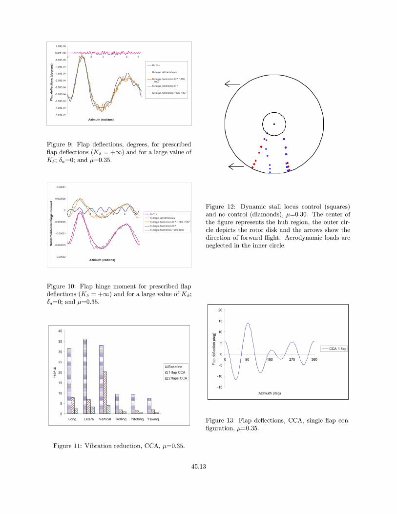
The optimal flap deflection required for the vi-bration reduction in the single flap configuration isshown on Fig. 13. The maximum flap amplitudesare about 15o. Figure 14 displays the flap deflectionsfor the dual flap configuration; here again, the max-imum deflection of both flaps is about 15o. How-ever, actuator technologies based on smart materialsseverely limit flap deflections to a maximum of 5o.Furthermore, flap deflections of 15o are not accept-able from a practical implementation point of view.
45.7

Therefore, additional results taking into account ac-tuator saturation that allows practical limits on flapdeflections have been obtained. The maximum al-lowable flap deflection for the cases considered herewas set to 4o, which is the value considered in anearlier study [28]. Saturation limits are imposedusing the approach described in a previous section.Results for vibration reduction are presented in Fig.15 for the single and dual flap configurations. Thevertical hub shear is unchanged, but vibratory hubshear reduction is not affected by saturation; re-ductions of 70-80% are obtained again. However,vibratory hub moments are reduced 60-85% insteadof 80-90%.
These results indicate that vibration reductionwith the single flap configuration operating with andwithout saturation limits is similar. However, theflap operating without saturation limits reduces vi-bratory hub loads by an additional 10-30% whencompared to the saturated flaps. These results areconsistent with the observation made in an earlierpaper [28] where the effects of dynamic stall werenot included.
The flap deflections with and without saturationfor the single flap configuration are shown on Fig.16. The maximum allowed flap deflections occursat ψ = 225o, that is just before a large portion ofthe blade enters dynamic stall. This result confirmsthat the main feature of the control is to postponedynamic stall entry, shown in Fig. 12. When satu-ration is not taken into account, flap deflections areunconstrained, and large deflections can occur whileproducing only a small amount of vibration allevia-tion. This appears to be the case on the advancingportion part of the rotor disk.
The influence of pretwist on the vibration alle-viation capability of the actively controlled flap isconsidered next. The baseline and controlled vi-bratory hub shears and moments are presented inFig. 17, when the pretwist angle is a linear func-tion of r, with θpt = 0o at the root and θpt = −8o
at the tip of the blade. The baseline vibrations aresmaller (between 25% and 50%) than their counter-parts without pretwist. The controlled vertical hubshear displays a 40% reduction with respect to thebaseline, which is similar to the vertical hub reduc-tion obtained without pretwist. The other vibratoryhub shears and moments are reduced 50-60%. Fig-ure 18 depicts the dynamic stall locus, as definedby flow separation and reattachment, without con-trol (diamonds) and with control (squares). Thedynamic stall area changes little in the presence ofcontrol. This is due to the large angles of attack (upto 19o) at the root of the blade, due to the pretwist
distribution.
The robustness of vibration alleviation using anactively controlled flap in the presence of freeplayis also examined. The baseline vibratory shears andmoments, when the freeplay angle is allowed to havefour different values between 0o ≤ δa ≤ 1.14o, aredepicted in Fig. 19. The vibratory hub shears andmoments do not change by more than 10% when thefreeplay angle varies, however for δa = 1.14o, thevertical shears increases by 25%. The flap deflec-tions for each value of the freeplay angle are shownin Fig. 20. The maximum flap deflection whenδa = 0o is less than 0.1o. The two characteristicsevident in Fig. 9, namely, small amplitude oscilla-tions at the spring fundamental frequency and smallfrequency flap deflection history for hinge momentequilibrium, are visible again. Over most of the az-imuth range, the values of the flap deflection arebelow −δa.
Next, results in the presence of CCA optimal con-trol are presented for the single flap configuration.The baseline and controlled vibratory hub shearsand moments are presented in Fig. 21. The verticalhub shear is reduced at least by 40% for all valuesof δa considered. Therefore, the presence of freeplaydoes not jeopardize the effectiveness of the ACF asa vibration alleviation device. As the freeplay an-gle increases, however, there is a degradation in thereduction of the longitudinal hub shear and rollingand pitching hub moments. The flap deflections cor-responding to the above vibration reduction resultsare represented in Fig. 22. The maximum flap de-flection increases with the freeplay angle, from 6o
for δa = 0o to 14o for δa = 1.14o. All flap deflectionhistories display low flap deflections in the advanc-ing blade region and large peaks over the retreatingblade and dynamic stall region.
Vibration alleviation results obtained when satu-ration limits are imposed are presented in Fig. 23.The vertical hub shear is reduced by about 30% forall values of the freeplay angle. Therefore, even ifthe alleviation of other vibratory shears and mo-ments is moderately degraded when the freeplay an-gle increases, the saturated ACF is an effective vi-bration alleviation device. The flap deflections as-sociated with this vibration reduction are depictedin Fig. 24. The flap deflection histories are similar,and large peaks before and after the dynamic stallregion are reproduced for all values of the freeplayangle.
45.8

Conclusions
A fairly extensive numerical simulation of vibra-tion reduction at high speed flight using activelycontrolled flaps has been conducted. The ONERAdynamic stall model was used for the representationof the unsteady aerodynamic loading in the sepa-rated flow region. Both single flap and dual flapconfigurations were studied, and limits on flap de-flections were imposed. The principal conclusionsobtained are provided below.
1. The ACF implemented either as a single flapor in the dual flap configuration is an effec-tive means for alleviating the unfavorable ef-fects due to dynamic stall.
2. The physical mechanism for reducing vibra-tions due to dynamic stall appears to be associ-ated with delayed entry of the retreating bladeinto the stall region; combined with a reductionin the stall region over the area of the disk
3. The dual flap configuration appears to have anadvantage over the single flap configuration inits ability to alleviate the undesirable effectsassociated with dynamic stall.
4. The actively controlled flap, implemented in ei-ther single or dual flap configurations, is moreeffective at alleviating dynamic stall effectsthan the HHC approach studied in Ref. 13.The primary reason for the effectiveness of ACFis due to the fact that it represents a local con-troller, that is inherently more suitable for deal-ing with local effects such as dynamic stall. TheHHC approach affects the entire blade and thusis at a disadvantage when attempting to allevi-ate local effects.
5. Imposition of flap deflection limits, and theappropriate treatment of saturation play animportant role in the ability of the ACF, inboth configurations, to achieve alleviation ofdynamic stall related effects. Therefore, a care-ful treatment of these issues is necessary for thepractical implementation of the ACF in rotor-craft.
6. Pretwist distributions have a minor influenceon the vibration alleviation effectiveness of theACF.
7. Vibration alleviation is not jeopardized by thepresence of freeplay type of nonlinearity. Thevibratory hub shear reduction is not diminishedby the introduction of freeplay, and a moderate
degradation of the reduction of other vibratoryhub shears and moments is noticed.
Acknowledgment
Partial support from the FXB Center for Rotaryand Fixed Wing Air Vehicle Design, and DAADGrant 19-02-1-0202 from ARO with Dr. G. Ander-son as grant monitor are gratefully acknowledged.
References
[1] Friedmann, P. P. and Millot, T. A., “Vibra-tion Reduction in Rotorcraft Using Active Con-trol: A Comparison of Various Approaches,”Journal of Guidance, Control, and Dynamics ,Vol. 18, No. 4, 1995, pp. 664—673.
[2] Millott, T. A. and Friedmann, P. P., “Vibra-tion Reduction in Helicopter Rotors Using anActively Controlled Partial Span Trailing EdgeFlap Located on the Blade,” NASA CR-4611,1994.
[3] Myrtle, T. F. and Friedmann, P. P., “Appli-cation of a New Compressible Time DomainAerodynamic Model to Vibration Reductionin Helicopters Using an Actively ControlledFlap,” Journal of the American Helicopter So-ciety , No. 1, 2001, pp. 32—43.
[4] de Terlizzi, M. and Friedmann, P. P., “ActiveControl of BVI Induced Vibrations Using a Re-fined Aerodynamic Model and ExperimentalCorrelation,” 55th Annual Forum of the Ameri-can Helicopter Society , Montreal, Canada, May1999, pp. 599—618.
[5] Friedmann, P. P., de Terlizzi, M. and Myrtle,T. F., “New Developments in Vibration Re-duction with Actively Controlled Trailing EdgeFlaps,”Mathematical and Computer Modeling ,Vol. 33, 2001, pp. 1055—1083.
[6] Straub, F. K., “Active Flap Control for Vi-bration Reduction and Performance Improve-ment,” Proceedings of the 51st American Heli-copter Society Forum, Fort Worth, Tex., May1995, pp. 381—392.
[7] Straub, F. K. and Charles, B. D., “Com-prehensive Modeling of Rotors with TrailingEdge Flaps,” Proceedings of the 55th Forumof the American Helicopter Society , Montreal,Canada, May 1999.
45.9

[8] Chopra, I., Milgram, J. and Straub, F. K.,“Comprehensive Rotorcraft Aeroelastic Analy-sis with Trailing Edge Flap Model,” Proceed-ings of the 52th Forum of the American Heli-copter Society , Washington, D. C., June 1996,pp. 715—725.
[9] Friedmann, P. P., “Rotary-Wing Aeroelastic-ity - Current Status and Future Trends,” Pro-ceedings of the 39th AIAA Aerospace SciencesMeeting and Exhibit , AIAA Paper No. 2001-0427, Reno, Nev., January 2001.
[10] Shin, S. J. and Cesnik, C. E. S., “ForwardFlight Response of the Active Twist Rotor forHelicopter Vibration Reduction,” Proceedingsof the 42th AIAA/ASME/ASCE/AHS/ACSStructures, Structural Dynamics and MaterialsConference, AIAA Paper No. 2001-1357, Seat-tle, Wash., April 2001.
[11] Wilbur, M. L., Mirick, P. H., Yeager, W. T.,Langston, C. W., Shin, S. J., and Cesnik, C.E. S., “Vibratory Loads Reduction Testing ofthe NASA/Army/MIT Active Twist Rotor,”Proceedings of the American Helicopter Society57th Annual Forum, Washington, D. C., May2001.
[12] Leishman, J. G., Principles of Helicopter Aero-dynamics , Cambridge University Press, Cam-bridge, 2000.
[13] Nguyen, K., “Active Control of HelicopterBlade Stall,” AIAA Dynamics Specialists Con-ference, AIAA Paper No. 96-1221, Salt LakeCity, Utah, April 1996.
[14] Petot, D., “Differential Equation Modeling ofDynamic Stall,” La Recherche Aerospatiale,Vol. 5, 1989, pp. 59—71.
[15] Leishman, J. G. and Beddoes, T. S., “A Semi-Empirical Model for Dynamic Stall,” Journalof the American Helicopter Society , , No. 4,1989, pp. 3—17.
[16] Fulton, M. and Ormiston, R. A., “Small-ScaleRotor Experiments with On-Blade Elevons toReduce Blade Vibratory Loads in ForwardFlight,” Proceedings of the 54th Annual Forumof the American Helicopter Society , Washing-ton, D. C., May 1998, pp. 433—451.
[17] de Terlizzi, M., Blade Vortex Interaction andits Alleviation Using Passive and Active Con-trol Approaches , Ph.D. thesis, University ofCalifornia, Los Angeles, 1999.
[18] Depailler, G. and Friedmann, P. P., “Allevia-tion of Dynamic Stall Induced Vibrations Us-ing Actively Controlled Flaps,” Proceedings ofthe 58th Forum of the American Helicopter So-ciety , Montreal, Canada, June 2002.
[19] Tang, D. M. and Dowell, E. H., “Flutterand stall response of a helicopter blade withstructural nonlinearity,” Journal of Aircraft ,Vol. 29, 1992, pp. 953—960.
[20] Brase, L. O. and Eversman, W., “Applicationof Transient Aerodynamics to the StructuralNonlinear Flutter Problem,” Journal of Air-craft , Vol. 25, No. 11, 1988, pp. 1060—1068.
[21] Johnson, W., A Comprehensive AnalyticalModel of Rotorcraft Aerodynamics and Dynam-ics, Vol. I: Theory Manual , Johnson Aeronau-tics, Palo Alto, CA, 1988.
[22] McCormick, B. W., Aerodynamics of V/STOLFlight , Academic Press, New York, 1967.
[23] Wenzinger, C. J. and Harris, T. A., “Wind-Tunnel Investigation of a NACA 23012 Airfoilwith Various Arrangements of Slotted Flaps,”NACA Report 664, 1939.
[24] Depailler, G. and Friedmann, P. P., “Re-duction of Vibrations due to DynamicStall in Helicopters using an ActivelyControlled Flap,” Proceedings of the 43rdAIAA/ASME/ASCE/AHS/ACS Structures,Structural Dynamics and Materials Confer-ence, AIAA Paper No. 2002-1431, Denver,Colo., April 2002.
[25] Peters, D. A., “Toward a Unified Lift Model forUse in Rotor Blade Stability Analyses,” Pro-ceedings of the 40th Forum of the AmericanHelicopter Society , Arlington, Va., May 1984.
[26] Peters, D. A., Bayly, P. and Li, S., “A Hy-brid Periodic-Shooting, Autopilot Method forRotorcraft Trim Analysis,” Proceedings of the52th Forum of the American Helicopter Soci-ety , Washington, D.C., June 1996, pp. 780—792.
[27] Johnson, W., “Self-Tuning Regulators forMulticyclic Control of Helicopter Vibration,”NASA TP-1996, 1982.
[28] Cribbs, R. and Friedmann, P. P., “Ac-tuator Saturation and its Influence onVibration Reduction by Actively Con-trolled Flaps,” Proceedings of the 42nd
45.10

AIAA/ASME/ASCE/AHS/ACS Structures,Structural Dynamics and Materials Confer-ence, AIAA Paper No. 2001-1467, Seattle,Wash., April 2001.
[29] Myrtle, T. F., Development of an ImprovedAeroelastic Model for the Investigation of Vi-bration Reduction in Helicopter Rotors UsingTrailing Edge Flaps , Ph.D. thesis, Universityof California, Los Angeles, 1998.
[30] Prechtl, E. F., Design and Implementation ofa Piezoelectric Servo-Flap Actuation Systemfor Helicopter Rotor Individual Blade Control ,Ph.D. thesis, Massachusetts Institute of Tech-nology, 2000.
Table 1: Elastic blade configuration
Rotor DataNb = 4 cb = 0.05498Lb
ωF1 = 1.123 Cdo = 0.01ωL1 = 0.732 Cmo = 0.0ωT1 = 3.17 ao = 2πγ = 5.5 σ = 0.07Helicopter DataCW = 0.00515XFA = 0.0 ZFA = 0.3XFC = 0.0 ZFC = 0.3
Table 2: Flap configurations
ccs = 0.25cbSingle Flapxcs = 0.75Lb Lcs = 0.12LbDual Flapx1cs = 0.72Lb L1
cs = 0.06Lbx2cs = 0.92Lb L2
cs = 0.06Lb
K
f
Figure 1: Model for the torsional spring constraintacting on the flap.
a
f
p
Slope is K
Hinge moment
ae
f
Figure 2: Hinge moment as a function of flap de-flection.
45.11

Deformed
Elastic Axis
Undeformed
Elastic Axis
Deformed
Blade
Undeformed
Blade
z3
y3
x3
x4
Ω
Figure 3: Schematic representation of the unde-formed and deformed blade/actively controlled flapconfiguration.
W0:
W1:
D0:
D1:
Figure 4: Normal velocity distributions correspond-ing to generalized airfoil and flap motions W0, W1,D0, and D1.
0%
69% 81%
69% 75% 89% 95%
100%
(a) single-flap configuration
(b) dual-flap configuration
Figure 5: Single and dual flap configurations.
0
5
10
15
20
25
30
35
40
45
50
*10
^-4
K=+
K large
K large
Harmonics 0-7, 1006,
1007
K large
Harmonics 0-7
K large
Harmonics 1006, 1007Long. Lateral Vertical Pitching YawingRolling
Figure 6: Baseline vibrations for prescribed flap de-flections (Kδ = +∞) and for a large value of Kδ;δa=0; and µ=0.35.
0.00E+00
1.00E-07
2.00E-07
3.00E-07
4.00E-07
5.00E-07
6.00E-07
7.00E-07
8.00E-07
9.00E-07
1.00E-06
0 200 400 600 800 1000 1200 1400 1600 1800
Harmonic of flap deflections (/rev)
Harm
on
icam
pli
tud
e(d
eg
rees)
Figure 7: Fourier analysis of the flap deflection δffor a large value of Kδ; δa=0; and µ=0.35. Frequen-cies are in per rev.
0.00E+00
1.00E-07
2.00E-07
3.00E-07
4.00E-07
5.00E-07
6.00E-07
7.00E-07
8.00E-07
9.00E-07
1.00E-06
0 1 2 3 4 5 6 7 8 9 10 11 12 13 14
Harmonic of flap deflections (/rev)
Harm
on
icam
pli
tud
e(d
eg
rees)
Figure 8: Fourier analysis, limited to lower frequen-cies, of the flap deflection δf for a large value of Kδ;δa=0; and µ=0.35. Frequencies are in /rev.
45.12
-4.50E-04
-4.00E-04
-3.50E-04
-3.00E-04
-2.50E-04
-2.00E-04
-1.50E-04
-1.00E-04
-5.00E-05
0.00E+00
5.00E-05
0 1 2 3 4 5 6
K =+
K large, all harmonics
K large, harmonics 0-7, 1006,1007
K large, harmonics 0-7
K large, harmonics 1006, 1007
Fla
pd
efl
ecti
on
s(d
eg
rees)
Azimuth (radians)
Figure 9: Flap deflections, degrees, for prescribedflap deflections (Kδ = +∞) and for a large value ofKδ; δa=0; and µ=0.35.
-0.00002
-0.000015
-0.00001
-0.000005
0
0.000005
0.00001
0 1 2 3 4 5 6 K=+K large, all harmonics
K large, harmonics 0-7, 1006, 1007
K large, harmonics 0-7
K large, harmonics 1006-1007
No
nd
imen
sio
nalh
ing
em
om
en
t
Azimuth (radians)
Figure 10: Flap hinge moment for prescribed flapdeflections (Kδ = +∞) and for a large value of Kδ;δa=0; and µ=0.35.
0
5
10
15
20
25
30
35
40
Long. Lateral Vertical Rolling Pitching Yawing
*10^
-4
Baseline
1 flap CCA
2 flaps CCA
Figure 11: Vibration reduction, CCA, µ=0.35.
Figure 12: Dynamic stall locus control (squares)and no control (diamonds), µ=0.30. The center ofthe figure represents the hub region, the outer cir-cle depicts the rotor disk and the arrows show thedirection of forward flight. Aerodynamic loads areneglected in the inner circle.
-15
-10
-5
0
5
10
15
20
0 90 180 270 360
Azimuth (deg)
Fla
pdeflection
(deg)
CCA 1 flap
Figure 13: Flap deflections, CCA, single flap con-figuration, µ=0.35.
45.13

-20
-15
-10
-5
0
5
10
15
20
0 90 180 270 360
Azimuth (deg)
Fla
pdeflection
(deg)
CCA Inboard flap
CCA Outboard flap
Figure 14: Flap deflections for dual flap configura-tion, CCA, µ=0.35.
0
5
10
15
20
25
30
35
40
Long. Lateral Vertical Rolling Pitching Yawing
*10^
-4
Baseline
1 flap Saturation
2 flaps Saturation
Figure 15: Vibration reduction with saturation lim-its, µ=0.35.
-15
-10
-5
0
5
10
15
20
0 90 180 270 360
Azimuth (deg)
Fla
pdeflection
(deg)
CCA 1 flap
Saturation 1 flap
Figure 16: Flap deflections, effect of saturation,µ=0.35.
0
2
4
6
8
10
12
14
16
Long. Lateral Vertical Rolling Pitching Yawing
*10^
-4 Baseline
1 flap CCA
Figure 17: Vibration reduction, CCA, pretwist,µ=0.35.
Figure 18: Dynamic stall locus control (squares) andno control (diamonds), pretwist, µ=0.30. The cen-ter of the figure represents the hub region, the outercircle depicts the rotor disk and the arrows show thedirection of forward flight. Aerodynamic loads areneglected in the inner circle.
45.14

0
5
10
15
20
25
30
35
40
45
50
Long. Lateral Vertical Rolling Pitching Yawing
*10
^-4
äa=0º
äa=0.29º
äa=0.57º
äa=1.15º
Figure 19: Baseline vibrations for different values ofthe freeplay angle, µ=0.35.
-1.4
-1.2
-1
-0.8
-0.6
-0.4
-0.2
0
0.2
0 1 2 3 4 5 6
Azimuth (rad)
Fla
pd
efl
ecti
on
s(d
eg
)
äa=0º
äa=0.29º
äa=0.57º
äa=1.15º
Figure 20: Baseline flap deflections for different val-ues of the freeplay angle, µ=0.35, and without con-trol.
0
5
10
15
20
25
30
35
40
45
50
Long. Lateral Vertical Rolling Pitching Yawing
*10
^-4
Baseline äa=0º
CCA ä a =0º
CCA ä a =0. 29º
CCA ä a =0. 57º
CCA ä a =1. 15º
Figure 21: Vibration reduction, CCA, for differentvalues of the freeplay angle, µ=0.35, single flap con-figuration.
-15
-10
-5
0
5
10
15
0 1 2 3 4 5 6
Azimuth (rad)
Fla
pd
efl
ecti
on
s(d
eg
)
äa=0º
äa=0.29º
äa=0.57º
äa=1.15º
Figure 22: Flap deflections, CCA, for different val-ues of the freeplay angle, µ=0.35.
0
5
10
15
20
25
30
35
40
45
50
Long. Lateral Vertical Rolling Pitching Yawing
*10
^-4
Baseline äa=0º
Saturation äa=0º
Saturation äa=0.29º
Saturation äa=0.57º
Saturation äa=1.15º
Figure 23: Vibration reduction, saturation, for dif-ferent values of the freeplay angle, µ=0.35, singleflap configuration.
-6
-5
-4
-3
-2
-1
0
1
2
3
4
0 1 2 3 4 5 6
Azimuth (rad)
Fla
pd
efl
ecti
on
s(d
eg
)
äa=0º
äa=0.29º
äa=0.57º
äa=1.15º
Figure 24: Flap deflections, saturation, for differentvalues of the freeplay angle, µ=0.35.
45.15