Embed Size (px)
Citation preview
(10 - 55 VDC & 20 - 40 VAC)
Allen Bradley60-2728-1 Reflector Type Photo Eye
UL 325 Compliant
Formerly model 42 GRU-9001
Mount Photo Eyeto outside of lead
gate post, run wiringin conduit or flex.
Weld or bolt thereflector bracket
to outside of latchpost, parallel with
the photo eye.
SENSITIVITY
OUT
DK LT
POWERMARGIN(red) (yellow)
(green)
Front of Unit
Installation Instructions
Set Dark Switch to Dark ON.
Set Sensitivity near Max.
Wire per chart below.
Yellow LED indicates that the unit is receiving power.
Loosely Mount Photo Eye.
Solidly Mount Reflector, level or square with and aimed at the Photo Eye’s Lens.
Adjust Photo Eye until Red LED is steady. Then tip Up & Down and Side to Side, until Red LED goes out. This will determine the four outer most limits of aim. Go to center in both directions (Horizontal & Vertical Center.) Hold in this spot & tighten. Tap on the Photo Eye mount to test stability and accuracy.
Brown + Power RedWhite N.C. Do Not UseOrange COM GreenBlack N.O. WhiteBlue - Power Black
Unit has a 6’ Cable
WIRING Use 4 ConductorWire color
*See light status instructions on next page.*
Page 1 of 2

Yellow = Power On
Green = Relay Energized
RED =(steady) Aim OK
(flashing) Short Circuit or Overload
Normal
Yellow & Green LED.There is an obstruction,unit needs cleaned orre-aimed, the reflectoris missing, damagedor needs cleaned.
LIGHT STATUSIn Dark On Mode
If unit is in Light Mode, all 3 LED’sON indicates Normal status.
If Yellow only is on, it indicates anobstruction or out of aim scenario.Relay outputs will be backwards(normally open will read normally
closed & NC will read NO).
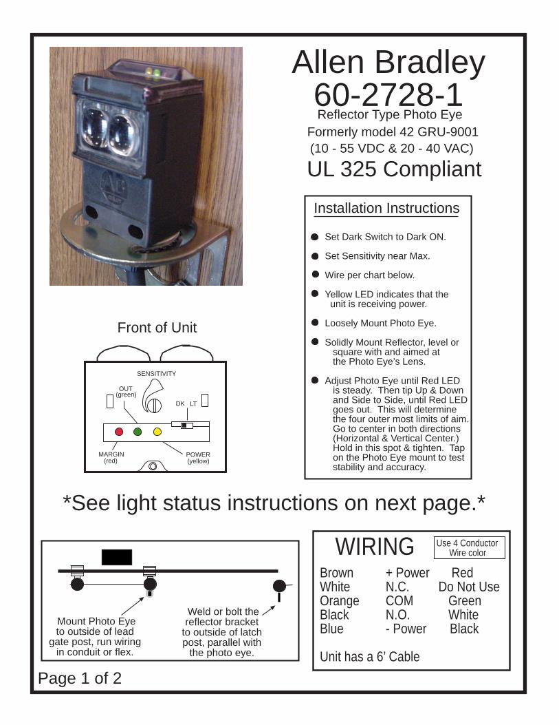
Allen Bradley60-2728-1 Reflector Type Photo Eye
SENSITIVITY
OUT
DK LT
POWERMARGIN(red) (yellow)
(green)
Front of Unit
Troubleshooting
Typical scenario, gate won’t close.
Clean dust, dirt, etc. from the photo eye lenses and the white reflector. It’s best to use Rain X. This may be the only problem. If the gate still won’t close, continue.
Loosen the screw holding down the plexiglass cover on top, rear of the photo eye.
Photo Eye should be in DARK MODE. If not, verify that it is installed per instructions.
Yellow LED will be on if unit is receiving power.
Green LED will be on if unit is obstructed, not properly aimed,reflector is damaged or dirty.
Red LED will be on if unit is properly aimed and not obstructed.
Red LED will be flashing if there is a dead short or if the unit is receiving too muchpower.
To re-aim the Photo Eye, loosen the large black plastic Photo Eye nut at the bottom of the bracket. See aiming the instructions in the Installation Instructions box on Page 1.
Page 2 of 2
Sensing
Yellow & Red LED.