Embed Size (px)
DESCRIPTION
All About Emission
Citation preview

All About Emission Control
www.walker-eu.com


All About Emission Control 3
INTRODUCTION
Due to the emergence of the new European emission control guidelines (Euro I, II, III and the recent Euro IV) which came into force in January 2005, the exhaust system and all its elements have now become more important than ever owing to its direct impact on engine consumption and tuning.
As from 1993 with all petrol engines, and from 1997 with all diesel engines, it became mandatory within European Community countries to equip all new vehicles with catalytic injection systems.
This measure, contrary to the belief of most people, makes the exhaust system one of the most sophisticated parts of the 4-stroke engine, because the performance of this engine depends directly on the accuracy of the back pressure levels produced from the exhaust system.
Using the correct exhaust system will ensure that the engine always works with the right air-fuel mixture, always providing the maximum power while maintaining minimum fuel consumption. It will also help to extend the working life of other important parts of the engine – valving system, silencers, catalytic converters, lambda sensors, etc.
Walker®, a worldwide leader in emission control systems and one of today’s most important manufacturers of Original Equipment, with more than 80 % of its total production invested in this business, has prepared this report with the aim of clearly explaining the importance that our exhaust system has with regard to the working life of an engine, and its performance and consumption levels. We would also like to bring to the attention of all installers, and end users of these systems, the critical, and sometimes unknown aspects of exhaust manufacturing qualities, and the direct relationship between the real working life and the final price of the product. We will also explain in detail everything you need to know about the European homologation process of these products and their direct impact on the consumption and performance of the engine.
Oscar F. Oskarsson Training Manager Tenneco Europe, Africa & Middle East
All About Emission Control Table Of Content4
Introduction 2
1 - Main Functions of the Exhaust System 6
• Emission Control 6 Catalytic converters, DPF, SCR, etc
• Sound Reduction 6 What is “sound” and how we can control it
• Correct Canalisation of the Exhaust Gases Towards the Outside 6 Effects of some of the exhaust gases in human health
• To Optimise the Engine Efficiency in a 4-Stroke Engine 6 How a 4-stroke engine works 7 What is the overlap time and why is it used 8 Relation between overlap time and engine performance 8 Effects of wrong backpressure 8
- Problems due to a positive backpressure - Problems due to a negative backpressure
2- Possible Causes of Exhaust System Failures 10
• Causes of Muffler Replacement 10
• Exhaust Problems Due to Material Failure 10
• Common Causes of Catalytic Converter Failures 12
3 - Manufacturing a Quality Modern Exhaust System 13
• What Is Aluminized Steel 13
• Are All Types of Aluminized Steel the Same Quality 13
• Working Life vs. Manufacturing Quality 13
• Original Equipment Quality Compared to Aftermarket Quality 14
4 - The Homologation Process (European guidelines) 15
• Approval Tests 15
• Homologation Marks on Exhausts and Catalytic Converters 17
• Differences Between Homologated, and Universal Exhaust Systems 18
5 - Main Components of Modern Vehicles Exhaust System 21
• Acoustic Absorption Materials 21 • E-Glass fibre • Biosil wool
TABLE OF CONTENT

Table Of Content All About Emission Control 5
• Types of Mufflers 21 • Absorption Muffler 21 • Reflection Muffler 22 • Mixed Muffler 22 • Semi-Active Muffler (S.A.M.) 22 • Spun Shape Muffler and Clam Shell Muffler 22
• Catalytic Converter 23 • Ceramic Monolith vs. Metallic Monolith 23 • Advantages of Metallic Monolith 24 • Advantages of Ceramic Monolith 25 • The Chemical Reactions 25 • Types of Catalytic Converter 26
• Diesel Particulate Filters (DPF) 27
• Selective Catalytic Reduction (SCR) 28
• Lambda Sensor 29 • Types of Lambda Sensors 29 • Zirconium Dioxide Lambda Sensor • Titanium Oxide Lambda Sensor • Broadband and Wideband Lambda Sensor
6 - Walker ® is a Leader in Emission Technologies for Original Equipment 32
• Emission Technologies for Environmental Mandates 32
• More Original Equipment Products for Emission Control 33
• Our Original Equipment Customers 33
• Research 33
7 - Walker ® Product Range 34
• Mufflers 34
• Catalytic Converter 34
• Complementary Products 34
8 - 4G AGAR 35
9 - 4T Program 35

MufflerDPF
DOC
Oxy-Cat
All About Emission Control Main Functions of the Exhaust System6
MAIN FUNCTIONS OF THE EXHAUST SYSTEMAs mentioned in the introduction, one of the most important factors required for the correct performance of a modern vehicles engine is the exhaust system. It is a fact that the key function of the exhaust system is virtually unknown to the majority of the population. The purpose of this section is to clarify, one by one, the main functions of the exhaust system and its relationship to the engines performance, (power and fuel consumption).
Emission ControlOne of the most important functions of the exhaust system nowadays is the emission control. All exhaust systems now need to be designed, and manufactured, with a requirement to reduce as much as possible the pollutants included in exhaust gases coming out from the combustion chamber before those gases are released from the exhaust system into the atmosphere. To accomplish this task with success, the exhaust system needs to have a precise amount of backpressure and should include other active elements, e.g. catalytic converters, lambda sensors, particulate filters, etc, making the exhaust gases cleaner, before leaving the exhaust system and passing into the atmosphere.
Sound Reduction Sound is defined as any pressure variation within an air or fluid medium, which may be detected by the human ear. The two most important characteristics that must be known in order to evaluate the sound/noise are its amplitude and frequency. The amplitude, which is the height of the sound wave from peak to trough, determines the loudness or intensity. The wavelength determines the frequency, pitch or tone of the sound. Explained in a more simplified way, sound is a wave of air in movement, the faster it moves the louder it will sound to us. All conventional exhausts are designed and manufactured in order to decrease the speed of the exhaust gases (and by this the noise level) before these gases are released into the atmosphere.
Correct Canalization of the Exhaust Gases towards the OutsideIn all combustion processes, where the fuel (diesel or petrol) is burnt, some dangerous components are produced which should be released from the vehicle’s engine to the atmosphere via the exhaust system. Those dangerous elements include carbon monoxide (CO), unburnt hydrocarbons (HC), nitrogen oxides (NOx), particulate matter and others. Some of these components are highly carcinogenic like the MTBE contained in the unleaded fuel as an antiknock additive, and compounds like 3-nitrobentrazone and 1.8-dinitropirene, contained in diesel emissions. We need to deal separately with the diesel carcinogenic components, 3-nitrobentrazone showed the highest result known so far in the AMES test, the test more accepted to determine the carcinogenic potential of a compound. In addition, the 1.8-Dinitropirene compound, also present in the diesel emissions was until the discovery of 3-nitrobentrazone, the most carcinogenic compound ever discovered by mankind.
To Optimise Engine Efficiency in a 4-stroke EngineThe key factor when building an exhaust system is the effort which must be made by the exhaust gases to pass through the system and then out into the atmosphere. This effort is what we call backpressure of the exhaust system. The vehicle manufacturing companies invest hundreds of thousands of euros in the design of engines that can provide us with maximum performance, but with minimum consumption, and the whole of this investment can be completely wasted if the backpressure levels are not the correct ones for this specific engine. On the other hand, it is almost impossible to pass the European environmental guidelines (Euro IV) if the backpressure level of the exhaust system is not exactly correct.
Main Functions of the Exhaust System All About Emission Control 7
Summary of Euro Guidelines
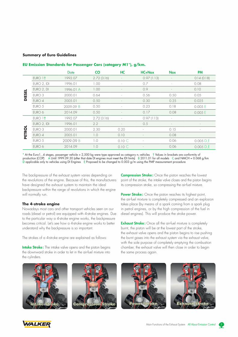
EU Emission Standards for Passenger Cars (category M1*), g/km.
Date CO HC HC+Nox Nox PM
DIE
SEL
EURO 1† 1992.07 2.72 (3.16) - 0.97 (1.13) - 0.14 (0.18)
EURO 2, IDI 1996.01 1.00 - 0.7 - 0.08
EURO 2, DI 1996.01 A 1.00 - 0.9 - 0.10
EURO 3 2000.01 0.64 - 0.56 0.50 0.05
EURO 4 2005.01 0.50 - 0.30 0.25 0.025
EURO 5 2009.09 B 0.50 - 0.23 0.18 0.005 EEURO 6 2014.09 0.50 - 0.17 0.08 0.005 E
PET
RO
L
EURO 1† 1992.07 2.72 (3.16) - 0.97 (1.13) - -
EURO 2, IDI 1996.01 2.2 - 0.5 - -
EURO 3 2000.01 2.30 0.20 - 0.15 -
EURO 4 2005.01 1.0 0.10 - 0.08
EURO 5 2009.09 B 1.0 0.10 C - 0.06 0.005 D,EEURO 6 2014.09 1.0 0.10 C - 0.06 0.005 D,E
* At the Euro1...4 stages, passenger vehicle > 2,500 kg were type approved as catagory n1 vehicles † Values in brackets are conformity of production (COP) A Until 1999.09.30 (after that date DI engines must meet the IDI limits) B 2011.01 for all models C and NMCH = 0.068 g/km D applicable only to vehicles using DI Engines E Proposed to be changed to 0.003 g/m using the PMP measurement procedure
The backpressure of the exhaust system varies depending on the revolutions of the engine. Because of this, the manufacturers have designed the exhaust system to maintain the ideal backpressure within the range of revolutions in which the engine will normally run.
The 4-stroke engineNowadays most cars and other transport vehicles seen on our roads (diesel or petrol) are equipped with 4-stroke engines. Due to the particular way a 4-stroke engine works, the backpressure becomes critical. Let’s see how a 4-stroke engine works to better understand why the backpressure is so important.
The strokes of a 4-stroke engine are explained as follows:
Intake Stroke : The intake valve opens and the piston begins the downward stroke in order to let in the air-fuel mixture into the cylinders.
Compression Stroke : Once the piston reaches the lowest point of the stroke, the intake valve closes and the piston begins its compression stroke, so compressing the air-fuel mixture.
Power Stroke : Once the piston reaches its highest point, the air-fuel mixture is completely compressed and an explosion takes place (by means of a spark coming from a spark plug in petrol engines, or by the high compression of the fuel in diesel engines). This will produce the stroke power.
Exhaust Stroke : Once all the air-fuel mixture is completely burnt, the piston will be at the lowest part of the stroke, the exhaust valve opens and the piston begins to rise pushing the burnt gases into the exhaust system via the exhaust valve, with the sole purpose of completely emptying the combustion chamber, the exhaust valve will then close in order to begin the same process again.

Exhaust ClosesIntake Opens
Exhaust Stroke
CompressionStroke
Power Stroke
Intake Stroke
Exhaust OpensIntake Closes
Cooling circuit
Cooling circuit
Exhaust valve Intake valve
The effect of using a non-homologated catalytic converter or a muffler that generates greater backpressure than the original one.
Gases on fire
All About Emission Control Main Functions of the Exhaust System8
Valve Overlap : Due to the special shape of the combustion chamber where the air-fuel mixture is burnt, the engineers realized that, in order to completely empty the combustion chamber of burnt gases on the exhaust stroke, they needed to open the intake valve just before the exhaust valve closes, maintaining both valves (intake and exhaust) open together for a specific amount of time (miliseconds) allowing clean air-fuel mixture into the combustion chamber, forcing all of the burnt gases into the exhaust, so beginning the four stroke cycle again, with a perfectly clean air-fuel mixture, ensuring maximum engine performance during this cycle.
The camshaft is the part of the engine which controls movement of the exhaust and intake valves. This is a solid part made of cast iron and cannot be adjusted manually. The backpressure we need to implement into the exhaust system directly depends on the valve overlap time, which is preset and controlled by the shape of the camshaft. As we have seen previously, the system is designed to completely empty the combustion chamber of burnt gases in order to obtain maximum performance in all the cycles.
What Would Happen when the Backpressure of the Exhaust System Is Higher than the Backpressure Needed ?When the exhaust has higher backpressure than the one specified by the manufacturer (the gases need more time to escape from the exhaust system towards the outside) a certain quantity of the burnt gases will remain inside the combustion chamber after the valve overlap time, mixing with the fresh air-fuel mixture during the intake stroke. Because of that, this new mixture of fresh and burnt gases will give a slower explosion during the power stroke, and therefore at the end of this stroke, part of the mixture will still be burning (Less fuel burnt per time unit) resulting in a loss of engine power, and the characteristic red colour of the exhaust manifold, which is caused when gases which are still burning escape from the cylinder towards the exhaust system during the exhaust stroke. Under these extreme working conditions the exhaust valves will be quickly damaged (melting) loosing their sealing function, which will allow part of the mixture to escape from the combustion chamber to the exhaust system through the bad valve sealing during the compression strokes, causing an even greater loss of engine power. On the other hand when the burning gases reach the catalytic converter, the monolith of the catalytic converter will begin to melt. The speed of the melting process will depend on how great the backpressure problem is: it can vary widely from a couple of minutes, to a few months. The melting process of a catalytic converter’s monolith takes place due to the high temperature of these burning gases, in some cases the temperature can reach over 1,800 ºC. It is important to remember that a ceramic monolith will melt at 1,400 ºC while the metallic monolith will melt at 1,600 ºC.
Picture of a 3 Catalytic Converter Modern Exhaust System

Cooling circuit
Cooling circuit
Exhaust valve Intake valve
The effect of using a non-homologated catalytic converter or a muffler that generates greater backpressure than the original one.
Unburnt fuel mixed with exhaust gases
Main Functions of the Exhaust System All About Emission Control 9
This problem normally appears when : I Installing an exhaust or catalytic converter that has not
been specifically designed for that specific engine (applications for other cars).
II Installing non-homologated products (universal silencers or catalytic converters) in the system.
III When assembling a full, or part system by welding the pipes, mufflers or catalytic converters, this will result in the reduction of the internal diameter of the pipes during welding.
IV With the internal rusting of pipes and mufflers. This process will produce a variation in the diameter of the internal dimensions, and as a result giving a variation in the backpressure within the system.
What Happens if the Backpressure Is Lower than that Needed for this Engine ?When the exhaust system has a lower backpressure than the one designed by the engine manufacturer, the gases will escape faster from the combustion chamber during the exhaust stroke. During the overlap time the burnt gases will flow easily and faster through the exhaust system, because of this, a small part of the new air-fuel mixture entering the chamber via the intake valve, will have time to escape through the exhaust valve during the process of forcing out the burnt gases from the combustion chamber. It is therefore easy to understand that if we have lost a small quantity of air-fuel mixture from the combustion chamber due to lower backpressure, we will lose engine power, because there will be less fuel burnt per time unit than in a correct backpressure situation. Also because the gases will flow faster through the exhaust system towards the atmosphere, the noise level will be higher in comparison with the noise produced in the correct situation (exhaust system with correct backpressure). This kind of failure also causes the monolith of the catalytic converter to melt and this is due to the unburnt air-fuel mixture, which escapes from the compression chamber during the valve overlap as it reaches the monolith surface, where the normal working temperature is between 500 ºC and 900 ºC. When the fuel reaches the monolith surface of the catalytic converter it will automatically begin to burn (at 1,800 ºC) producing micro melting areas over the surface. If the problem continues, the catalytic converter will be completely destroyed. The length and time of this process will depend on how great the backpressure problem is.
This problem normally appears when :I Installing non-homologated silencers, catalytic converters or
pipes to the vehicle (especially sport silencers which are noisier than the OE ones).
II Due to an air leakage in the exhaust system, caused by rust or violent vibration.
III Making a hole in the exhaust housing or side cover to “take out the water”. It is very important to remember that the material used for manufacturing the silencers and pipes is aluminized steel, and once it is perforated, the protective layers of aluminium are destroyed, allowing the acids created inside the silencers to come into direct contact with the laminated steel layer, which will accelerate the rusting process, making the hole larger within a very short period of time, greatly increasing the backpressure problem.
IV This problem also appears when deliberately removing the contents of a catalytic converter by destroying the monolith or installing an empty catalytic converter onto a vehicle.
View of a Low Backpressure exhaust

All About Emission Control Possible Causes Of Exhaust System Failures10
Causes of Muffler ReplacementThe exhaust system can be damaged
because of a multitude of problems; nearly all of them can be grouped into three different categories: rust, vibrations and incorrect use. All these three categories of problems generate the same type of failure
by creating backpressure problems. As we have seen in previous chapters
backpressure problems in catalyzed cars (petrol or diesel) affect the performance, the consumption, and more importantly produces fusion of the catalytic converters monolith, failure of which generally ends in an expensive engine repair at a garage. The good news is that all these problems are very easy to prevent, by using homologated exhaust parts and following the advice outlined in the following paragraphs.
Exhaust Problems due to Material Failure RustRust is the most obvious and easy to detect. There are two types of rust processes, the external rust (from outside to inside) due to the external elements. A good example of this is the rust produced on the unprotected metallic parts (including the exhaust system) of the car, this occurs when they are in contact with salt and water found on the roads of areas with colder climates. When there is a risk of very low temperatures, local authorities put salt on the roads in order to decrease the freezing point of the water. The other type of rust is the internal rust (from inside to outside), which is produced in the mufflers due to the contact with the internal water and other chemical substances and deposits generated by condensation of the exhaust gases when the exhaust system is cold. This problem affects the majority of cars that are normally used only for short distances, and for that reason, the exhaust system never reaches the proper temperature to evaporate completely the water that has accumulated inside due to the condensation process. It is a good rule to have in mind that an average petrol car needs to run continuously for approximately 40 km at normal revolution level
(between 2,000 rpm and 4,000 rpm) to completely dry the exhaust system.
Internal rust is a very significant problem, when it appears at the surface of the muffler the inside parts
(pipes and walls) will appear either severely damaged or completely destroyed. This situation can produce important variations to the backpressure levels of the whole exhaust system.
Vibrations Muffler substitution, which is due to failure related to vibrations in the system, has nowadays become one of the most common reasons why installers change a muffler. We can be sure that the vast majority of all the mufflers changed due to vibration problems in the system, can be eliminated by just understanding why the muffler, or pipe breakages, are produced and avoiding the causes that generate them. In the following paragraphs, we will try to throw some light onto all those common problems, explaining how to detect each one of them, and providing you with some useful information in order to avoid them.
Vibration due to old or damaged exhaust rubber supports is the most common of all the exhaust problems due to vibrations and the most easily avoided. As you all know the exhaust supports are mainly made of rubber, this material has a life span that depends on the external environmental conditions. The environmental factor that affects most rubber supports is the working temperature. When we expose the rubber to a high temperature for some time, the chemical composition of rubber gradually changes becoming harder and less elastic. These chemical changes cause the exhaust’s rubber supports to transmit any impacts to the exhaust system instead of absorbing them, resulting in severe damage to the system. The way to see if the problem is due to the rubber supports is to check the area where the pipes are welded to the mufflers. If the problem is caused by the rubber supports becoming hardened or brittle, the pipe will be loose at the muffler cover, and you will see a perfect circle or semicircle, as if you had cut the cover with a pair of scissors (this is caused by the enormous amount of vibrations produced in this connection area in all possible directions.) Good advice to avoid this type of problem is to always change the old rubber supports of the exhaust system with new ones when you change a broken muffler.
POSSIBLE CAUSES OF EXHAUST SYSTEM FAILURES

Possible Causes Of Exhaust System Failures All About Emission Control 11
Vibration due to old or damaged engine rubber supports and / or elastic joining of the transmission : The main function
of engine rubber supports is to absorb the vibrations (lateral movements) generated by
the engine while it is running. These elements are also submitted to a faster chemical deterioration process due to the high temperatures and pressures existing in those areas. In some rear-wheel drive
cars, vibration problems become even worse because the elastic joining of the
transmission can become damaged or worn out. This situation will generate more side movements of the exhaust that will increase dramatically, the lateral tensions of the exhaust system parts located closer to the engine. Nowadays, all the cars that need this type of care have it included in the service book which states when the engine rubber supports, and the elastic joining of the transmission should be changed (generally between 40,000 km to 80,000 km). In order to find out if we are facing this type of problem, we should look to see the way the pipe has broken.
Generally, due to the transversal torsion movements which are trying to twist the pipe firstly to one side, and then to the other side, the pipe will be broken close to the curves, and never with a perfect circle shape (as in the previous case). This type of problem generates an irregular dented surface because of the constant transverse torsion forces. The best way of avoiding this problem is by just following the service interval for changing the engine rubber supports and the elastic joining of the transmission.
Problems due to wrong application or non-homologated exhaust parts The problems we face when we install the wrong muffler (non-homologated for this car) are that we always get a different backpressure level than the one specifically designed by the manufacturer’s engineers for the optimum performance of this car. This situation independently of the level (higher backpressure or lower backpressure) generates a list of important engine problems. As explained in previous chapters, an engine with the wrong backpressure will always lose during the overlap time, a small amount of petrol (liquid or burning) and air. With high backpressure giving a reading greater than 1.03 on the lambda factor of the four gases analyzed, the car will fail the government emission test (MOT). At the same time, all the fuel lost during the overlap time will end up at the catalytic converter monolith, melting it slowly but constantly. At the same time this wasted petrol increases the consumption level and the car driver experiences a loss of power at the normal range of revolutions. The best and the only advice in order to avoid this problem, is always to replace the worn out or faulty exhaust system parts with homologated ones.
Exhaust broken due to vibrations due to worn out engine rubber supports. Exhaust broken due to vibrations due to worn out exhaust rubber supports. Exhaust damaged due to material fatigue in the housing area. Exhaust broken due to vibrations of worn out exhaust rubber supports. Exhaust manifold broken due to vibrations produced due to worn out engine rubber supports or elastic joining of the transmission.

All About Emission Control Possible Causes Of Exhaust System Failures12
Common Causes of Catalytic Converter Failures In general, we can confirm that in a properly serviced car (petrol or diesel), the average working life of the catalytic converter varies between 100,000 km and 150,000 km depending on the model, and on the way it is driven by the owner. That does not mean that you cannot find cars over 150,000 km that are still able to pass the MOT emission control test with good results, but it is much more unlikely. Apart from normal wear, the catalytic converter can be damaged in many different ways, let us now look at all of them:
Poisoning by lead of the catalytic converter monolith lead, coming from leaded petrol, and additives designed to increase the compression rate of petrol (octane index), also after combustion in the cars combustion chamber it produces lead oxides that cover the surface of the catalytic converter monolith. This process stops the precious metals coming in contact with the exhaust gases, stopping the catalytic chemical reactions. It has been demonstrated that only three tanks of leaded petrol are required to destroy the catalytic converter function. This problem is very simple to identify either in the lambda sensor or in the monolith. In this specific case, the surface of the monolith or the cover of the lambda sensor, which has been in contact with the gases, appears covered by lead, which gives those areas a characteristic dark grey colour (lead colour).
Poisoning by phosphorous deposits of the oil. Every time we burn oil, a specific amount of phosphorous is generated in the process. If the vehicle engine burns more than one litre of oil (from the sump) per 1,000 km, then the amount of phosphorous becomes so high that it generates white hard (like white cement) deposits over the surface of the monolith, which will cover the precious metals avoiding any catalytic reaction. If the situation persists, in time those deposits will end up blocking drastically the flow of gases through the monolith cells, also generating the problem of high backpressure levels with all the consequences to the engines integrity, and performance.
Poisoning due to wrong air/fuel mixtures. Every time an engine is run with the wrong air/fuel mixtures (rich or lean), the exhaust gases contain a certain amount of soot and/or unburnt fuel. Soot generates black colour (like coil particles) deposits over the catalytic converter surface, which
with time will produce a malfunction of the catalytic converters chemical reactions, and increases in the backpressure level. This problem appears often when the engine is running with an air/fuel rich mode activated for long periods of time (probably due to a broken lambda sensor, broken temperature sensor, etc.).
Melted monolith due to a defective spark (ignition system). One of the fastest and most destructive problems that a catalytic converter can experience is running with a hot engine that has a defective spark. This problem will produce large amounts of unburnt hydrocarbons (HC) that will literally melt the surface of a catalytic converter monolith. The time that this process can take varies widely from a few minutes to a few weeks depending on the number of revolutions, the temperature of the monolith, and the amount of unburnt hydrocarbons left in the exhaust gases. This problem normally appears due to poor maintenance of the ignition system (defective spark plugs, rusted wires, rusted or damaged connectors, wrong adjustment in the spark timing, etc.)
Impact by stones or other road obstacles . The ceramic catalytic converter monolith is a fragile element, which breaks easily when receiving a direct impact. We need to remember that the vast majority of the catalytic converters have a ceramic monolith. Once the monolith breaks, the cells of the different parts of the monolith move one from the other generating noise and a big increase in backpressure within the exhaust system.
Backpressure problems of the exhaust system .As we have seen in previous chapters, backpressure problems are one of the most common and important problems that petrol or diesel catalyzed injection cars are facing nowadays. These type of problems generally appear when we have within the system, a non-homologated exhaust system, rusted exhausts, broken catalytic converter monoliths (due to impacts or melting process), blocked mufflers (due to rust processes, or loose parts of a catalytic converter monolith), air leakage in the exhaust system, etc. The importance of this problem lies in the fact that the result of all the backpressure problems are a faster worn out process of the catalytic converter and a constant melting process of the monolith surface. On top of this, because the engine is losing small amounts of petrol in each power stroke, the car loses power increasing the level of consumption.

Manufacturing a Quality Modern Exhaust System All About Emission Control 13
MANUFACTURING A QUALITY MODERN EXHAUST SYSTEM Nowadays all manufacturers of exhaust components within the European Community area mainly use aluminized steel in their manufacturing process. All Aftermarket manufacturers and nearly all Original Equipment manufacturers, that manufacture spare parts for the retail market, use aluminized steel for these units.
What Is Aluminized Steel ?The aluminized steel is composed of two materials, a layer of laminated steel and a protective cover of aluminium. If we add aluminium to only one of the sides of the steel layer, we call it single-layer aluminized steel, but if we add one layer of aluminium on each side of the steel layer we call it 2-layer aluminized steel. With this type of material the laminated steel provides resistance to impacts and internal stresses while the aluminium protective cover gives protection against corrosion.
Laminated SteelAluminium
Aluminium
It is not possible to determine just by “looking” what quantity of aluminium is contained in a silencer manufactured in aluminized steel, because in all types of aluminized steel the external colour will be the same (aluminium colour).
Are all Types of Aluminized Steel the Same Quality ?The answer to this question is no, the level of resistance to corrosion depends on the thickness of the aluminium cover which protects the laminated steel. To help us determine the quality of the aluminized steel we have purchased, the manufacturers describe it with a number, this tells us how many grams of aluminium there is covering each of the laminated steel layers per square meter, followed by the word single-layer or 2-layer indicating whether it is protected on one or both sides with aluminium. As we said previously, on 120 gr/m2 2-layer, this means that the aluminized steel is covered with 120 grams of aluminium for each square meter on each of its sides, (This kind of steel is a high quality aluminized steel used by Original Equipment manufacturers for their retail products as well as the Aftermarket manufacturers for homologated production). On the other hand, if the aluminized steel was 120 gr/m2 single-layer, this would tell us that it is covered with a 120 gr/m2 but only on one side (that means it would have half the aluminium of the previous example.) It would leave one of the sides of the laminated steel layer without any extra protection against corrosion.
Example of single-layer aluminized steel
Laminated Steel
Aluminium
What Are the Most Commonly Used Aluminized Steels in the Manufacturing Process of Exhaust Systems, and What Is the Relation between the Materials Used and the Working Life of the Exhaust? The picture below shows the different qualities of the aluminized steel used in the manufacturing of after market exhaust pipes, and spare parts, from the lowest quality and price, up to those used in the highest performing products which includes as in the last example of the chart two sheets of 2 - layer aluminised steel (0.7 mm thickness of 120 gr/m2 aluminized steel + 0.5 mm of 150 gr/m2 aluminized steel).
The price of the aluminium is much higher than the cost of the laminated steel, the lower the quality of aluminized steel (lower quantity of aluminium) the cheaper it would be and the quicker it would rust, putting other systems of the car in danger, and decreasing the overall performance of the engine.
Manufacturing Qualities of Aluminized Steel
Aluminized Steel 80/m2 one leaf 1.2 mm
12-18 Aluminized Steel 120/m2 one leaf 1.2 mm
18-24 Aluminized Steel 120/m2 two leafs (0.5 mm + 0.7 mm)
30-36 Aluminized Steel 120/m2 two leafs (0,5 mm 150 gr/m2
+ 0.7 mm 150 gr/m2)
Working life in months
6-12

All About Emission Control Manufacturing a Quality Modern Exhaust System 14
The manufacturers of the cheaper silencers, apart from not following any homologation guidelines, generally use a very poor quality aluminized steel, with a much lower level of aluminium, and in some cases they are using mild steel in the internal pipes of the silencers. Because of this, in a very short period of time the internal corrosion significantly varies the backpressure levels of the system, and therefore the power and consumption is affected, also putting other engine parts such as the catalytic converters, lambda sensors, etc, at high risk of damage.
It is important to note that the thickness of the aluminised steel layer (its aluminium content) is a key factor that determines the working life of the silencer and guarantees the optimum performance of the engine during its complete working life.
In the example shown above we have selected a standard 1.2 mm thick sheet commonly used in Original Equipment (OE) and Aftermarket (AM) retail manufacturing.
It is important to note that the installation of double sheets in the silencer housings contain double the amounts of aluminium than those with a single sheet housing, increasing the silencer’s overall working life, as well as making the exhaust quieter.
Original Equipment (OE) Quality Compared to Aftermarket Quality.In order to talk about OE quality we would need to talk about three different levels depending on two factors: when it will be installed on the vehicle? And for whom this product will be available?
The levels available are :
OE (Original Equipment for manufacturing quality) : This quality is only produced for car manufacturers’ assembly lines. This is the quality that you will find installed in the car when it is new, and due to the long warranty periods given by the OE manufacturers when they sell the car (3 to 8 years) these products are usually made of stainless steel 0.8 mm to 1.2 mm. These exhausts are produced solely for assembly lines, and because of this are not generally sold to end consumers or OE dealer.
OES (Original Equipment First Supply) : If some part of the OE car exhaust system experiences a warranty problem inside the first months of the vehicles working life, and the aluminized steel exhaust is not enough to support the rest of the warranty period, then the OE dealer will replace the OE problem part with another of exactly the same quality (stainless steel) in order to ensure that this part will support the rest of the warranty period. In this case, the quality selected would be the same as the OE explained in the previous point, but if the warranty period remaining is inferior to two years (which makes it suitable to use an exhaust made of aluminized steel instead of stainless steel) then the manufacturer will replace the part with one made of aluminized steel. It is important to know that OES parts (stainless steel) are only for OE dealer internal use (warranty problems) and are never sold to the end consumer.
OESS (Original Equipment Second Supply) : The quality used in all the OESS exhaust systems is aluminized steel (generally double layer, one leaf layer 120 gr Al/m2) and this is the quality that is produced to be sold in the OE dealers as Original Equipment quality for end users.
After this, it is clear that buying a homologated exhaust from an AM, or buying it from an OE dealer is the same in terms of material and rust resistance because both are made of aluminised steel.
Three simple questions regarding aluminized steel : 1. What is aluminized steel ?2. Is all aluminized steel of the same quality ? 3. What are the most commonly used aluminized
steels in the manufacture of exhaust systems, and what is the relation between the materials used and the working life of the exhaust?

The Homologation Process All About Emission Control 15
THE HOMOLOGATION PROCESSThe Homologation of the different exhaust system parts (silencers and catalytic converters) is a process of comparison between the Original Equipment part, and the part that we want to homologate for the Aftermarket. This process will guarantee to the end consumer, and the installer, that the unit to be installed is equal in backpressure and noise levels to the Original Equipment designed by the vehicle manufacturer. This fact will guarantee that installing a homologated exhaust system, (silencer or catalytic converter) means that the engine will always maintain its performance level and its performance level is equivalent to being equipped with an original system. It is important to note that the installation of non-homologated silencers or catalytic converters is prohibited, and is considered an illegal activity within the European Community area, the same as selling non-homologated tyres or laminated glass for car windows. The local authorities will penalize non-fulfilment of these guidelines.
To better understand the importance that homologation has for the end user or installer, and to avoid the possibility of being cheated by illegal companies which work outside of the European Community law, we need to know which homologation tests are necessary and mandatory for all silencers and catalytic converters to be granted the homologation code and certificate.
These tests are always done by government representatives from the Department of Trade and Industry of the country where the tests are taking place. These tests are standard for every European country, and in order to receive the homologation code and certificate, all these tests need to be passed successfully. If, during the tests of a silencer or catalytic converter, the unit fails any of these tests the complete process will be finished without obtaining the homologation for this unit.
Despite these homologation tests being done by external test laboratories such as TÜV in Germany or INTA in Spain, the Department of Trade and Industry in each European country is the only Department that can grant a homologation certificate. When comparing an homologation document, we always need to be sure that the format used for homologation is the correct one (it is standard for all European Community countries and is included in the European guidelines), and should be signed and stamped by the appropriate person from the Department of Trade and Industry. If the document does not conform to these regulations the product will not be homologated and therefore not be validated by the authorities.
Tests for silencers and catalytic converters in order to obtain the homologation code and certificate are:
Static Noise test : In an anechoic chamber, with the vehicle in neutral gear and the original exhaust system fitted, the inspector measures the noise level produced while the engine is accelerated up to 2/3 of the revolutions shown on the vehicle’s technical specification when the car is providing maximum power. Then we replace the original part of the exhaust with the Aftermarket part that we want to homologate, and the test is repeated three times, taking as a valid value the medium rate of the three tests made to the part we want to homologate. To pass the test, the noise level of the Aftermarket part must always be lower than the one registered for the original. It is important to understand that due to this test no exhaust system or catalytic converter can be homologated if, when installed in the car, the noise levels are higher than those registered by the car’s Original Equipment.
Homologation tests are :Static noise testDynamic noise testBack pressure testAdaptability test Precious metals content (only for catalytic converters)
Example of Static Noise Test in an Anechoic Chamber

B B’
P’
A’A
Microphone Microphone
10 m
10 m
7.5 m 7.5 m
P
Noise measurement points - Exhaust gasses backpressure
Figure 1 Single Pipe
max 450 mm
min 150 mm
max 450 mm
Figure 2 Partially Double Pipe
min 150 mm
Two single measurement points link together to give only one value
max 450 mm
Figure 3 Double Pipe
min 150 mm
All About Emission Control The Homologation Process 16
Dynamic Noise test : This test is similar to the previous one but it is carried out on a circuit while the car is moving. The noise is measured using two microphones located as shown in the picture. To do this test we must measure the noise level while the car is moving three times in each direction (A to B and after B to A) in second gear and in third gear (6 times in total), taking as valid value the medium rate of the two worse values of the three obtained in each direction. To make the test correctly the car should cross the measurement area in second and third gear as well as maintaining engine revolution of up to 2/3 of the revolutions shown on the vehicle’s technical specification when the car is providing maximum power or cross the measurement area in second and third gear with a constant speed of 50 km/h. The first test is made with the Original Equipment exhaust, then we substitute the part of the exhaust system (silencer or catalytic converter), which we want to homologate, and repeat the previous test. To pass this test the noise level of the Aftermarket part must always be lower than the one registered for the Original Equipment part, and always lower than 74 dB. In this test we can also see that any silencer or catalytic converter that has a higher noise level than the one originally installed in the car, cannot be homologated in European Community countries.
Backpressure test : This test is also carried out by comparing the values of tests done on the Original Equipment product, and on the Aftermarket product.
To do this test, first we measure the backpressure on the exhaust manifold while the engine is running at a specific revolution range with the complete Original Equipment exhaust. Then the part we want to test is replaced in the system, and we repeat exactly the same test. In order to pass this test the percentage difference between the backpressure levels in both tests need to be less than +25 %, this means that the part that we are trying to homologate for the Aftermarket, needs to have a maximum difference of the 25 % backpressure registered with the Original Equipment part. This is the most difficult test to pass for the exhaust manufacturers, because to pass the two previous noise tests we need to have a little more backpressure in order to
decrease the speed of the gases escaping from the exhaust system, and therefore decreasing the noise levels in respect of the Original Equipment levels. On the other hand, small structural variations inside the silencer can cause greater variation in backpressure levels, and because of that, the exhaust or catalytic converter should be almost an exact copy internally of the Original Equipment unit.
This test helps us to understand that any universal silencer, or catalytic converter, cannot be homologated because these two concepts are actually opposites. The homologated silencer or catalytic converter has been developed for only one specific type of engine, and is almost an exact copy of the Original Equipment one. Contrary to this, universal units are sold for a certain range of vehicles depending on the size of their engines and the diameter of connection pipes, (e.g. a silencer or catalytic converter for all cars between 1,100 cc and 2,500 cc with 45 mm diameter pipes) because of this, the universal units will never ever have the proper backpressure levels necessary for the optimum performance of this engine, this in fact causes further damage to other parts of the engine, like the catalytic converter units, lambda sensors, valve seats, etc...

Platinum Rhodium Palladium
The Homologation Process All About Emission Control 17
Adaptability test : This test checks that the part we are trying to homologate has exactly the same fittings and similar shape as that of the Original Equipment part. This means that we should be able to fit the unit into the system without any adjustments such as bending pipes, or adding other external elements that were not in the original specification
It is important to note that in this test it is prohibited to weld over the exhaust system, because if we need to weld it, then it is because this part of the system is different from the original one, and it would be impossible for this part to pass the adaptability test.
This test demonstrates that any universal silencer, or catalytic converter, cannot be homologated because these products usually have universal fittings (just the pipes without connections) and they are normally different from the fittings used in the original system equipment.
Precious metals content test : This test is only done to catalytic converters, and it determines the content of precious metals (platinum, rhodium and palladium) in the monolith of the catalytic converter. This test guarantees to the end user that the catalytic converter contains the required amounts of precious metals, as stipulated in the European Environmental guidelines in order to be successful in its function of transforming harmful exhaust gases into non pollutant ones.
For the end user of the vehicle, it is a guarantee that he will receive exactly what he has paid for, because the cost of some of these precious metals is very high.
To do this test, the monolith of the catalytic converter (where the precious metals are contained) needs to be submerged in an acid solution and left there for the particular amount of time specified for this test. This acid solution will make the precious metals separate from the monolith, after which the metals are weighed separately to determine the percentage of those in relation to the volume of the monolith.
We need to be especially careful when buying these units, we must ask for sufficient guarantees in order to confirm that these catalytic converters are homologated (read the homologation codes carefully and ask for the homologation documents.) In general, the universal catalytic converters will have a much lower content of precious metals (around 5 times less than
homologated ones), which results in a very poor performance of these units. In addition, the backpressure of these units is usually wrong, because they are not designed for any specific engine model, and as we have seen before, this causes a loss of power in the engine, and an increase of fuel consumption, putting other engine parts at risk of further damage.
How Can We Recognize if a Silencer, or the Catalytic Converter Is Homologated?To know if a catalytic converter or silencer is homologated, following the European Community guidelines, you must check to see if the right homologation code is marked on the lower part of the unit housing. This code must always be placed in the lower part of the housing, because it will be checked at the government’s vehicle technical inspection centre.
We must always be certain that every silencer or catalytic converter has the right homologation certificates. These documents can be requested at any time by staff from vehicle inspection centres, as well as by the end user of the car. We need to note that the homologation codes are standard,
which means that its configuration, position and size, always follows specific criteria established in the European guidelines, and cannot be changed by anybody. This fact helps us to quickly differentiate
between the silencers and catalytic converters which are homologated, and
those which are not, and for this we need to remember that there are only three valid homologation codes for exhaust systems
and catalytic converters, which can be recognized as follows.
Picture of a Modern Exhaust System

All About Emission Control The Homologation Process 18
Homologation codes for silencers (two possibilities):
Homologation numberHomologation guidelineHomologation country
“1” Germany “6” Belgium “17” Finland “2” France “9” Spain “18” Denmark “3” Italy “11” UK “21” Portugal “4” Netherlands “12” Austria “23” Greece “5” Sweden “13” Luxembourg “Irl” Ireland
Guideline 70/157/EEC ‡ Nº 00Guideline 77/212/EEC ‡ Nº 01Guideline 84/424/EEC ‡ Nº 02Guideline 92/97/EEC ‡ Nº 03
030148a
2a/3 a/3a ≥ 8 mm
A. Guideline 70/157/ EEC it is important that all the numbers are in a straight line one after the other. The “e” must be small (not capital letter) and always appear inside the box together with a number, which identifies the country, if it is not like that then the homologation code is false
B. Regulation 59 of the United Nations. This code is similar to the previous one with all the numbers in a specific position. The number, which indicates the homologation country, is put in a circle together with the letter “E” which is always written as a capital letter followed by 59, which means that this unit meets the Regulation 59 of the United Nations. This code is completely legal but is rarely used nowadays because it is very old.
Homologation number
Homologation guideline
Regulation 59
Homologation country
E9 59 0301482a/3 a/3 a/3
a ≥ 8 mm

Homologation codes for catalytic converters (two possibilities):
The Homologation Process All About Emission Control 19
Homologation numberHomologation guidelineHomologation country
“1” Germany “6” Belgium “17” Finland “2” France “9” Spain “18” Denmark “3” Italy “11” UK “21” Portugal “4” Netherlands “12” Austria “23” Greece “5” Sweden “13” Luxembourg “Irl” Ireland
Guideline 70/157/EEC ‡ Nº 00Guideline 77/212/EEC ‡ Nº 01Guideline 84/424/EEC ‡ Nº 02Guideline 92/97/EEC ‡ Nº 03
030148a
2a/3 a/3a ≥ 8 mm
A. Guideline 70/220/EEC : It is important that the numbers are placed in a straight line one after the other. The “e” must be small (not capital letter) and always appear inside the box together with a number, which identifies the country, otherwise the homologation code is false. This code is the old homologation code version for catalytic converters, and it is difficult to find it nowadays.
Homologation number
Homologation guideline
UN Regulation 103
Homologation country
E1 103 0301482a/3 a/3 a/3
a ≥ 8 mm
B. Regulation 103 of the United Nations before it was approved for Europe. This code is similar to the second one shown for the exhaust, with all the numbers in a specific position. The number which indicates the homologation country is put in a circle together with the letter “E” which is always written as a capital letter followed by 103, which means that this unit meets the Regulation 103 of the United Nations (the previous version before it was approved by the UN). This code was used before the European countries approved the Regulation 103. It’s completely legal but is rarely used nowadays
Homologation number
Homologation guideline
UN Regulation 103
Homologation country
E1 103R 0301482a/3 a/3 a/3
a ≥ 8 mm
C. Regulation 103 of the United Nations (actual version). This code is similar to the last one shown. The number which indicates the homologation country is put in a circle together with the letter “E” which is always written as a capital letter followed by 103 which means that this unit meets the Regulation 103 of the United Nations. This code is the most common one nowadays in all cars manufactured after February 23 1997, and the catalytic converter needs to show the code related to the Regulation 103 (103R) stamped on the catalytic converter housing.

Installation of non-homologated mufflers or catalytic converters is prohibited and is considered an illegal activity within the European Community. Non-adherence to these guidelines can be penalized by the local authorities.
e 1 47 0123First 2 digits are allways 00, 01, 02 or 03
e 1 1 01235Number is composed of 2 digits + space + 4 digits
E 1 01 1235Only lowercase e is valid
e 1 00 0123
Only appears on one line
e 1 103R 031235Only capital E is valid
Examples of False Codes
on Products
All About Emission Control The Homologation Process 20
If Homologation Is Necessary, Why Don’t all Manufacturers Homologate their Silencers and Catalytic Converters for the Retail Market?The production cost of the homologated products are much higher than the universal parts, due to the fact that homologated parts need to be designed for each particular engine model following the backpressure and noise level standards of the Original Equipment parts.
The average development cost for a new silencer or a catalytic converter is about 5,000 € per reference, (which is payable for each reference, while the universal manufacturers use the same design for a huge amount of applications without taking into account the performance of the vehicles, their consumption levels and the wear and tear of other components.) On the other hand, the cost of these technical tests for the homologation of a silencer is 1,200 € per reference, and 10,000 € for the same tests of a catalytic converter due to the higher cost of the precious metals test.
Manufacturers selling non-homologated units have an unfair price advantage over the manufacturers selling homologated parts in the after market.
It is important to note that many of these illegal companies continue working nowadays because the majority of installers, and end users, do not know that full responsibility of any illegal parts installed in the exhaust system lies only with the installer, and not with the manufacturer, or the selling company.

Main Components Of Modern Vehicles Exhaust System All About Emission Control 21
Acoustic Absorption MaterialsAcoustic absorption materials are special kinds of elements that are used inside some type of silencers (absorption and mixed mufflers) in order to absorb the high frequencies of the sound produced when the exhaust gases exit the combustion chamber, and enter the exhaust system. Today in the manufacturing process we can find mainly two different elements:
E-Glass Fibre The E-Glass fibre is a white colour thermoplastic compound, very similar in texture to the nylon in the manufacturing of dolls hair. This element is introduced in the mufflers by an injector through an automatic process. E-Glass fibre does not absorb water; this helps the condensed water to evaporate faster when the exhaust system is heated. Another great property of the E-Glass fibre is the fact that this material does not change its chemical composition in the presence of water. This permits the E-Glass fibre to maintain the same performance regarding noise levels during all the working life of the product. E-Glass fibre can be used in all applications in which the working temperature is below 500 ºC (generally 2nd muffler or in new cars after the catalytic converter) Above this temperature, the E-Glass fibre which as we have said is a plastic compound, would reduce in size due to the extreme heat changing the internal backpressure and with it the noise level.
Biosoluble Mineral Wool (Biosil) or Biodegradable Mineral FibreThe Biosil wool, is an orange coloured mineral compound, very similar in texture to insulating material used in houses to insulate the house from temperature, and humidity. Due to its special texture (it is like a carpet). Biosil can be pre-moulded and introduced inside the exhaust to make the manufacturing process easier and precise. On the other hand in those cases where a pre-moulded shape can not be obtained due to a more complex shape of the internal parts of the exhaust, Biosil can be introduced by hand obtaining any shape that is needed. The big advantages of this product against the E-Glass fibre are its superior capacity of absorbing noise, and the fact that this product can be used in extremely hot conditions (over 500 ºC and up to 1,200 ºC) without any loss of performance. But on the other hand, Biosil wool material absorbs the water coming from the condensation of exhaust gases, making the evaporation process much longer. Biosil wool is also sensitive to continuous wet-dry periods, because in the presence of water the material changes its chemical composition, becoming harder and becoming thinner (compressed) due to this change the noise as well as the performance of the vehicle can be affected. Around year 2003 exhaust manufacturers start to use Biosil wool to replace the Basal wool, product that was used since that time for the same purpose because it was found carcinogenic. Since that time the use of Basal wool in exhaust manufacturing processes is prohibited in European Countries.
Types of Mufflers
Absorption MufflerThe name of these mufflers comes from the methodology used to control the noise level. High frequency sound is attenuated thanks to the material that covers the straight perforated tube that crosses from side to side of the interior part of the muffler.
This type of muffler design is especially effective in eliminating high frequencies, and gives low levels of backpressure. Low frequency noise is not absorbed by this muffler design.
MAIN COMPONENTS OF MODERN VEHICLES EXHAUST SYSTEM
Picture of a Exhaust Containing E-Glass Fibre

All About Emission Control Main Components Of Modern Vehicles Exhaust System22
Reflection MufflerAs the name indicates these mufflers use the reflection principle to control low frequency noise. This muffler works on the principle that when two equal and opposite sound waves meet head on, they destroy each other on impact.
In order to ensure that the reflection effect takes place inside the muffler, the design is key. The internal design of a reflection muffler includes different chambers separated by baffles that are connected by perforated pipes. Due to the increased resistance to flow of this design, the backpressure is higher than that of the absorption muffler.
Mixed MufflerA mixed muffler design is a combination of the absorption and reflection muffler; as a result, mixed mufflers are able to control all kinds of audible frequencies (low and high). More than 80 % of all the mufflers produced in the automotive industry are mixed mufflers.
Semi Active Muffler (S.A.M.)This is a special type of silencer that includes a revolutionary valve; this allows the muffler to maintain an optimum backpressure level at any phase of the revolutions. The way this valve works is by controlling the flow of gases through one of the internal muffler pipes. This action is achieved thanks to the S.A.M. valve opening or closing the internal pipe section, thus controlling the backpressure level of the whole exhaust system. Due to this innovative backpressure control, cars equipped with S.A.M. mufflers produces more power over all the revolution range as well as an excellent noise attenuation at low frequencies. Due to its design, the volume of the exhaust system can be reduced by approximately 30 %, which impacts directly in a decrease of the total weight of the exhaust system, and fuel consumption.
Spun Shape Muffler and Clam Shell MufflerDepending on the external shape of the exhaust housing and the manufacturing process to build it up, exhaust can be divided into two different types, The first is called a spun shape muffler, with two metal layers pressed to form a cylinder which houses the perforated pipe work. The second type is called a clam shell muffler. In this design, two metallic layers are pressed to form a “shell” again housing the perforated pipe work, with two equal shells used together to form the mixed muffler. Clam shell mufflers are always filled with Biosil wool to reduce noise levels
Semi Active Muffler (S.A.M.)
Internal View of a Reflection Muffler Internal View of a Reflection Muffler

ProtectionHousing
Interam Material Heat Shield
Light-off Ring
Monolith
Precious Metals
Monolith
Wash Coat
Main Components Of Modern Vehicles Exhaust System All About Emission Control 23
The Catalytic Converter Nowadays, catalytic converters are one of the main parts of our exhaust systems. These units are installed in all cars sold in the European Community countries, and their use has been mandatory since 1993 for petrol cars and 1997 for diesel cars. The function of these units inside the exhaust system is to transform the harmful gases (CO, HC, NOx) in the exhaust gases coming from the combustion chamber into other considered “clean” gases (CO2, H2O, N2), before these gases leave the exhaust system into the atmosphere. This process takes place inside the catalytic converter with the help of the catalytic metals: platinum, palladium and rhodium. These metals are placed over the surface of the monolith (metallic or ceramic) that is always in contact with the exhaust gases. The monoliths used for automotive applications have a honeycomb-like shape, with a high number of cells through which the exhaust gases pass on their way to the atmosphere.
When the monolith is warmed up (over 300 ºC) and exhaust gases come into contact with the precious metals placed over the surface of the monoliths cells, chemical reactions, which transform the harmful gases takes place. It is easy to see that the performance of the catalytic converter will be directly related to the amount of monolith surface that is in contact with the exhaust gases in a specific amount of time, as well as the quantity of precious metals placed over the surface of this monolith. It is an interesting fact that the surface of the monolith in contact with the exhaust gases in a specific amount of time is huge; for example, for a standard 1,600 cc car’s monolith, the surface of the monolith in contact with the exhaust gases will be more or less the same as the surface of a standard football pitch.
Ceramic Monolith vs. Metallic Monolith The ceramic monolith, as its name suggests, is made from a ceramic compound. The most widely used is a silicate called cordierite (2MgO2 Al2 O3 SiO). The monolith has a honeycomb-like structure with square
cells. In order to be shaped properly, the ceramic compound is heated to over 1,300 ºC until its consistency becomes that of a paste, and using an extrusion process the paste is forced through a mould to produce its honeycomb shape. Usually, the monoliths have an oval or cylindrical shape, although the design is quite flexible since it only depends on the type of mould used during the extrusion process.
Once the body of the monolith is formed, it must then be submitted to a process known as “wash coating”. During this process the active catalyst material is deposited in the so-called wash coat, the main components of the wash coat are base metal oxides (BMO), AL2O3, CeO2, and ZrO2, and also precious metals (PM), normally platinum, palladium and rhodium. This wash coat is placed over the monolith’s cell walls, by submerging the monolith in a colloidal solution containing the base metal oxides, and the precious metals. This process of “wash coating” is used for ceramic as well as for metallic monoliths.
The minimal quantities of precious metals, platinum, palladium and rhodium, which must adhere to the surface of the monolith are not random, but should be applied according to present European guidelines (and should be the same for metallic and for ceramics).
The mechanical characteristics of this type of monolith are :
Shape : Usually oval or cylinder.
Thickness of monolith walls : Approximately 100 microns.
Number of cells : Between 400 and 900 cpsi.
Fusion point of the cordierite : At approximately 1,450 ºC
Resistance to impact : Low. (Breaks)
Coef. of Thermal Expansion (CTE) :
0.002 cal/s-cm-oC (Very low).
Metallic Monolith vs. Ceramic Monolith
Internal View of a Ceramic Catalytic Converter
Internal View of a Ceramic Catalytic Converter

All About Emission Control Main Components Of Modern Vehicles Exhaust System24
On the otherhand we have the metallic catalytic converter, which has a monolith constructed from basic metal alloy materials. (for example FeCrAlloy, Kantal, etc.) The most common way of making these monoliths for the automotive industry is to combine flat and corrugated layers of this metal alloy in order to make the spiral-shaped monolith. The channels from where the exhaust gases subsequently escape are formed between the flat plate and the undulations of the corrugated one.
Once the spiral is formed, it is placed inside a metal cylinder that serves as a support chassis. These monoliths are almost always cylindrical due to their special manufacturing process. In the specific case of metal monoliths with a higher quantity of cells per square inch, the “wash coating” process can be carried out before it is formed into a spiral, because if the wash coating takes place once the monolith is formed (as in the case of the ceramic catalytic converters), it could create an obstruction of some cells due to its smaller size.
The mechanical characteristics of this type of monolith are :
Shape : Generally cylindrical.
Thickness of monolith walls : Approximately 25 Microns.
Number of cells : Between 800 cpsi and 1,250 cpsi.
Fusion point of the alloy : Approximately 1,600 ºC
Resistance to impact High, it does not fracture.
Coefficient of Thermal Expansion (CTE) :
(Very high).
Having checked the mechanical characteristics of both types of monolith, (metallic and ceramic) we are able to sum up a few advantages and inconveniences of these systems, and their usefulness in our petrol and diesel cars.
It will also help to understand why almost all catalytic converters (more than 90 % of total units), installed in Original Equipment, are ceramic catalytic converters.
Advantages of metallic monolith The metallic monolith allows the manufacturers to produce smaller catalytic converters, because these units have thinner cell walls. It also allows them to design monoliths with a higher number of cells, allowing greater surface contact of exhaust gases with precious metals, compared to ceramic monoliths. Due to the fact that these units have thinner monolith walls, the backpressure levels are generally lower compared to the ceramic ones of the same size. It is essential that the backpressure level of a replacement catalytic converter needs to be more or less equal to the level of the original Equipment unit in order to obtain the European homologation. This homologation process is mandatory for all the after-market exhaust and catalytic converters produced for European Community countries, and ensures that the homologated units will maintain maximum performance of the vehicle avoiding any other engine damage.
Better impact resistance : When the catalytic converter receives a strong impact, the metallic monolith does not break as the ceramic one does, instead, the metallic monolith deforms by changing its shape. When the monolith is deformed, in most of the situations the catalytic converter needs to be changed urgently because this deformity will destroy some monolith cells which will produce an increase of the backpressure levels in the exhaust system. This situation could produce a significant loss of power and cause serious damage to the car engine.
Metallic melting point is 150 ºC higher than the ceramic monolith : As we saw, the melting point of the metallic monolith occurs at around 1,600 ºC, 150 ºC higher than the melting point of the ceramic one which is approximately at 1,450 ºC. This quality gives the metallic monolith the capacity to resist the temperature a little bit better, because of that, when the engine has some problems (wrong backpressure, old spark plugs, problems with lambda sensor, etc…) the metallic monolith will remain working for a longer period than the ceramic one before it melts. On the other hand, if the problems are big (misfiring, broken spark plug, total failure of one cylinder, important mixture problems, compression problems) the differences will be very small, (minute) because the amount of petrol burning
View of a Damaged Catalytic Converter Due to an Impact with an External Object.
Internal View of a Metallic Catalytic Converter's Monolith
Manufacturing Procedure Used to Built Metallic Monoliths
OxidationPt
Lean Mixture
COHC
COH2OPt
Main Components Of Modern Vehicles Exhaust System All About Emission Control 25
inside the catalytic converter (over the monolith) is very high, and the temperature generated when the fuel burns is 1,800 ºC, which is far away from the melting point of both monoliths. We need to remember that the auto-ignition point of
the unleaded petrol is approximately 450 ºC, and the working temperature rate of a catalytic
converter is around 500 ºC. It means that every unburnt fuel particle leaving the combustion chamber with the exhaust gases, will burn automatically as soon as it touch the monolith surface. This petrol as we know produces temperatures over 1,800 ºC which will melt the monolith surface. The time that the monolith (metallic or ceramic) will resist once the melting process begins is directly related to the quantity of unburnt fuel contained in the exhaust gases, and the temperature of the monolith.
Advantages of the ceramic monolith Easy way to create different monolith shapes : Due to the way these monoliths are manufactured (by extrusion) the shape of the monolith can be varied very easily. As we have seen, the shape of the monolith only depends on the mould used to extrude the material. This shape can be cylindrical, elliptical, square or even asymmetric. This is one of the most appreciated qualities from the viewpoint of the car manufacturers.
Longer working life of the ceramic catalytic converters : This is due to two main factors; the first one concerns the roughness level of the monolith. The roughness level of the ceramic monolith walls is significantly higher than the roughness level of the metallic monolith.This fact makes the wash coating process better, and more efficient in the ceramic monolith. The second and most critical factor is the Coefficient of Thermal Expansion (CTE). In the ceramic monolith the CTE is very small compared to the metallic ones, it means that the ceramic monolith size varies very little with temperature variations. For the metallic monolith the situation is the opposite, the CTE is much bigger, this fact produces significant variations on the monolith size, depending on the temperature level, increasing its size when it is hot (remember that the working temperature rate for a catalytic converter is approximately 500 ºC) and decreasing when it is cool. The explanation of why the CTE is so important is simple, if we have a metallic painted surface, and we change the size of this surface (increasing and decreasing it) several times, over a period of time the surface will lose its paint cover. This is exactly what happens with the wash coat cover when submitted to high and continuous monolith size variations, and as soon as the monolith loses its wash coat cover, this unit completely loses its functionality, and needs to be replaced.
Lower manufacturing cost : Due to the fact that ceramic monoliths are produced by an extrusion process, the manufacturing cost of these units is lower in comparison to the same units manufactured in metallic monoliths. On the other hand, the quantity of precious metals (platinum, paladium and rhodium), which need to be included in the wash coating process, is fixed by the European guidelines and is the same for both types of monolith.
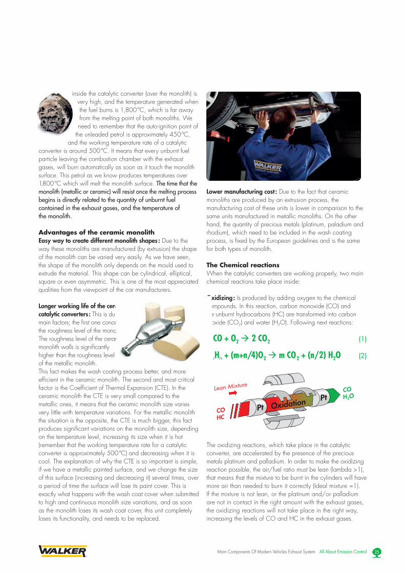
The Chemical reactionsWhen the catalytic converters are working properly, two main chemical reactions take place inside:
Oxidizing : Is produced by adding oxygen to the chemical compounds. In this reaction, carbon monoxide (CO) and the unburnt hydrocarbons (HC) are transformed into carbon dioxide (CO2) and water (H2O). Following next reactions:
2 CO + O2 2 CO 2 (1)
CmHn + (m+n/4)O 2 m CO 2 + (n/2) H2O (2)
The oxidizing reactions, which take place in the catalytic converter, are accelerated by the presence of the precious metals platinum and palladium. In order to make the oxidizing reaction possible, the air/fuel ratio must be lean (lambda > 1), that means that the mixture to be burnt in the cylinders will have more air than needed to burn it correctly (Ideal mixture =1). If the mixture is not lean, or the platinum and/or palladium are not in contact in the right amount with the exhaust gases, the oxidizing reactions will not take place in the right way, increasing the levels of CO and HC in the exhaust gases.

Catalytic ConverterIntake System
RhCOHCNOX
COH2ON2
Pt
ReductionRh
Rich Mixture
NOx
N2
CO2Rh
All About Emission Control Main Components Of Modern Vehicles Exhaust System26
Reduction : This type of chemical reaction consists of separating the oxygen of a compound, in order to create a new compound or molecule. The reduction reactions that take place inside automotive catalytic converters are accelerated by the presence of rhodium, and require rich air/fuel mixtures to take place. Reduction reactions are a method of transforming NOx molecules into nitrogen (N2), carbon dioxide (CO2) and in some cases water (H2O).
2 CO + 2 NO N2 + 2 CO2 (3)
CmHn + 2(m+n/4) NO (m+n/4) N2 + mCO2 + (n/2) H2O (4)
H2 + NO (1/2) N2 + H2O (5)
Types of Catalytic Converters Depending on the Number of Ways Catalytic converters can be classified in three groups based on the number of gases that each catalytic converter is able to transform: 2-way catalytic converters (two gases, CO and HC), 3-way catalytic converters with air intake (three gases CO, HC and NOx used in old US petrol vehicles) and 3-way catalytic converter with lambda sensor (three gases CO, HC and NOx used for petrol cars equipped with lambda sensor).
2-way catalytic converter These units are used in lean mixture engines, like diesel, or direct injection petrol engines like GDI, FSI. The precious metals present in the monolith are generally platinum, but can also be palladium, or even both at the same time. Platinum and palladium are metals that accelerate the transformation of the CO and HC by oxidizing reactions, transforming them into CO2 and H2O (see oxidizing reactions (1) and (2)). The reduction of NOx in these types of engines cannot take place in the catalytic converter, because these types of engines run all the time with lean air/fuel mixture and the reduction process requires a rich mixture to allow the reduction reactions. The reduction process in these engines takes place using other methods, like EGR or selective catalytic reduction systems that will be explained later. 2-way catalytic converters are also called oxidizing catalytic converters, or diesel catalytic converters.
3-way catalytic converter with air intake This type of catalytic converter is exclusively used in rich air/fuel mixture engines. Nowadays its use is effectively restricted to the US market. As its name indicates, these types of catalytic converters are able to transform three different gases (CO, HC and NOx). The internal design of these units includes two monoliths, each one of them with a very specific function in the transformation process. The first monolith in contact with the flow of exhaust gases coming from the engine (with rich air/fuel mixture) is a reduction monolith, and because of that, it is only equipped with rhodium. Thanks to this monolith, the NOx is transformed into N2, H2O and CO2. Unfortunately due to the type of air/fuel mixture (rich), oxidizing reactions (CO and HC) cannot take place in the same monolith due to the lack of oxygen. To solve the problem, the engineers add a second monolith but this time an oxidizing one, equipped with platinum and/or palladium inside the catalytic converter housing just after the reduction one. To transform the rich mixture into a lean mixture before accessing the second monolith, the engineers left a small space between both monoliths where thanks to a hole and a small pump the system receives atmospheric air (with 21 % of oxygen) which transforms the mixture present in this area into lean, allowing the oxidizing reactions (1) and (2) to take place.

Catalytic Converter
Lambda Sensor
Intake System
E.C.U.ΔUλ Uλ
Main Components Of Modern Vehicles Exhaust System All About Emission Control 27
3-way Catalytic Converter with Lambda Sensor Contrary to 3-way catalytic converter with air intake system that carry out the reduction reactions first and then the oxidation reactions in different monoliths, 3-way catalytic converters with lambda sensor carries out the reduction reactions, and oxidation reactions on the same monolith thanks to the lambda sensor and engine management system. That means that these types of catalytic converters are able to transform CO, HC and NOx into CO2, H2O and N2 on the same monolith and at the same time. For its correct operation, it is necessary that the air/fuel mixture relation should be near the Stoichiometric value (1:14,7). In order to allow the oxidizing reaction to take place, the system makes continuous changes in the air/fuel ratio of the mixture. First the injection system makes the mixture a little bit lean (>1) for some moments, just after, the system changes the mixture again into rich (<1) to allow the reduction reactions. This process of continually changing the mixture is done very fast (At 2,000 rpm. Around 3 times per second) being directly proportional to the number of revolutions.
Tubular Integrated Converter (TIC) Contrary to the standard manufacturing process of catalytic converters, where the housing is made from two shells of stainless steel or other metal rust resistant, tubular integrated converters are built in a one piece housing made from thin walled stainless steel tube produced in a hot rolled process. The manufacturing process controls the thickness of the material at each critical point to obtain the maximum mechanical resistance, as well as a better connection to the pipes of the exhaust system. Due to its special design, these units are lighter, and the durability is higher compared to the standard ones.
Close Coupled Converter Under this name we can include all those catalytic converters that are incorporated in the exhaust manifold. This design enables a catalytic converter to reach the light off point (temperature from which the catalytic converter starts to work properly) faster. This design contributes to optimum use of engine exhaust energy, and improves conversion efficiency
Diesel Particulate Filters (DPF)A diesel particulate filter, (also called DPF) is a device designed to remove diesel particulate matter, (soot), from the exhaust gas of a diesel engine. The efficiency of these elements is very high, often attaining efficiencies of over 90 %. A diesel-powered vehicle with a DPF installed will emit no visible smoke from its exhaust pipe. In order to collect the particulate matter, a method must be designed to get rid of it. Nowadays there are three different methods of achieving this. Some filters are single use (disposable), while others are designed to burn off the accumulated particulate, either through the use of a catalyst (passive), or through an active technology, such as a fuel burner, which heats the filter to soot combustion temperatures, or through engine modifications (the engine is set to run a specific way when the filter load reaches a pre-determined level, measured with sensors through the back pressure level, and temperature of the unit, either to heat the exhaust gases, or to produce high amounts of NO2, which will oxidize the particulates at relatively low temperatures). This procedure is known as “filter regeneration”. Fuel sulphur interferes with many “regeneration” strategies, so almost all jurisdictions that are interested in reducing particulate emissions, are also passing regulations governing fuel sulphur levels.
Picture of a Close Coupled Converter
View of the Tubular Integrated Converter (TIC) Products

Controller
Injector
T & Vol
NOx & T NOx & TSCR
catalyticconverter
Slipcatalyticconverter
DOCDPF
UCE
UREAtank
Mixer
Dispensingpump
All About Emission Control Main Components Of Modern Vehicles Exhaust System28
Selective Catalytic Reduction (SCR) It is a process where a gaseous or liquid reductant (most commonly ammonia or urea) is added to exhaust gas stream thanks to an injector connected to the exhaust pipe to later on be transformed into the catalyst. The reductant reacts with NOx contained in the exhaust gases into the selective catalytic converter to form H2O (water vapour) and N2 (nitrogen gas). Specialty selective catalytic converters for reduction are required to make an SCR system work, nowadays we can find two possible options in the market, vanadium-based catalyst (for lower temperature applications like ships, power plants, etc), or a catalyst with iron or copper zeolites in the wash coat. The performance of Fe- and Cu-exchanged zeolites urea-SCR is approximately equal to that of vanadium urea-SCR if the fraction of the NO2 is 20 % to 50 % of the total NOx. Zeolites offer improved durability at high temperatures, including an ability to withstand extended operation above 650 ºC and brief exposure to temperatures of 750 to 850 ºC. Thermal durability is particularly important for mobile SCR applications that incorporate the use of a diesel particulate filter (DPF) with forced regeneration. Vanadium catalysts are quickly deactivated at temperatures above 600 ºC. The reliance on an increased fraction of NO2 within the total NOx to
increase low temperature (sub -350 ºC) performance of zeolite catalysts typically requires the use of an upstream oxidation catalyst for NO to NO2, which in turn requires the use of fuels that are virtually sulphur-free to allow low-temperature oxidation of NO to NO2, and to prevent formation of sulphate particulate matter.
Ammonia or Urea, which is the best ?While ammonia offers slightly better performance, it is toxic and is difficult to handle safely. Urea is safer to handle, but not quite as effective. It has, however, to date been a more popular choice for engine manufacturers. In both cases, the reductant must be extremely pure, because the impurities can affect negatively the SCR catalytic converters. Typically, SCR catalytic converters require frequent cleaning even with pure reductants, as the reductant can cover the inlet surface of the catalytic converter monolith, while the exhaust gas stream temperature is too low for the SCR reaction to take place.
Research into reductant technology is continuing. A wide variety of suggestions have been made for alternative reductants, In Europe, SCR is a common choice for NOx control technology by engine manufacturers, and a variety of ammonia and urea brands are available, such as AdBlue for example.
Ammonia slipA common problem with all SCR systems is ammonia slip. The term describes exhaust pipe emissions of ammonia that occur when:1 - Exhaust gas temperatures are too cold for the SCR reaction
to occur. 2 - The injection device feeds too much reductant into the
exhaust gas stream for the amount of NOx.
A variety of strategies have been developed to deal with ammonia slip, including the use of extra catalysts after the SCR catalyst (also called : Slip Cat).
Technical problems with automotive SCR unitsIn order to ensure that the SCR unit remains free from contaminants, correct materials of construction must be used for both storage and dispensing. Manufacturers of the SCR unit have specified that, without using compatible materials of construction, ions can be passed from the dispensing materials into the porous head on the SCR unit. This can render the SCR unit ineffective, and reduce its life expectancy by more than 60 %. Equipment that may prove suitable for urea solution is often not compatible with AdBlue, and the common assumption that it is compatible has led to a number of systems failing prematurely.
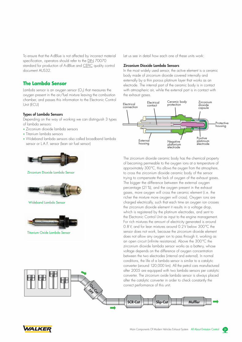
MufflerSlip-CatSCR-Cat
Oxi-Cat
DPF
Zirconium Dioxide Lambda Sensor
Titanium Oxide Lambda Sensor
Wideband Lambda Sensor
Electricalconnection
Electricalcontact
Ceramic bodyprotection
Zirconium dioxidecapsule
Protective housing
Positive platiniumelectrode
Externalhousing Negative
platanium electrode
Main Components Of Modern Vehicles Exhaust System All About Emission Control 29
To ensure that the A dBlue is not affected by incorrect material specification, operators should refer to the DIN 70070 standard for production of A dBlue and CEFIC quality control document AUS32.
The Lambda SensorLambda sensor is an oxygen sensor (O2) that measures the oxygen present in the air/fuel mixture leaving the combustion chamber, and passes this information to the Electronic Control Unit (ECU)
Types of Lambda Sensors Depending on the way of working we can distinguish 3 types of lambda sensors:• Zirconium dioxide lambda sensors• Titanium lambda sensors• Wideband lambda sensors also called broadband lambda
sensor or L.A.F. sensor (lean air fuel sensor)
Let us see in detail how each one of these units work:
Zirconium Dioxide Lambda Sensors In the most widely used sensor, the active element is a ceramic body made of zirconium dioxide covered internally and externally by a thin porous platinum layer that works as an electrode. The internal part of the ceramic body is in contact with atmospheric air, while the external part is in contact with the exhaust gases.
The zirconium dioxide ceramic body has the chemical property of becoming permeable to the oxygen ions at a temperature of approximately 300 ºC, this allows the oxygen from the atmosphere, to cross the zirconium dioxide ceramic body of the sensor trying to compensate the lack of oxygen of the exhaust gases. The bigger the difference between the external oxygen percentage (21 %), and the oxygen present in the exhaust gases, more oxygen will cross the ceramic element (i.e. the richer the mixture more oxygen will cross). Oxygen ions are charged electrically, such that each time an oxygen ion crosses the zirconium dioxide element it results in a voltage drop, which is registered by the platinum electrodes, and sent to the Electronic Control Unit as input to the engine management. For rich mixtures the amount of electricity generated is around 0.8 V, and for lean mixtures around 0.2 V below 300 ºC the sensor does not work, because the zirconium dioxide element does not allow any oxygen ion to pass through it, working as an open circuit (infinite resistance). Above the 300 ºC the zirconium dioxide lambda sensor works as a battery, whose voltage depends on the difference of oxygen concentration between the two electrodes (internal and external). In normal conditions, the life of a lambda sensor is similar to a catalytic converter (around 120,000 km). All the petrol cars manufactured after 2005 are equipped with two lambda sensors per catalytic converter. The zirconium oxide lambda sensor is always placed after the catalytic converter in order to check constantly the correct performance of this unit.

Common Wire Colour in Zirconium Dioxide Lambda Sensors
1 wire : Output 0.1 to 0.9 VoltColour Connection: Black Signal
2 wires : Output 0.1 to 0.9 VoltColour Connection / Alternative Colour: Black - Signal Black - Signal White - Earth Grey - Earth
3 wires : Output 0.1 to 0.9 VoltColour Connection / Alternative Colour: Black - Signal Blue - Signal White - Heater Black - Heater White - Heater Black - Heater
4 wires : Output 0.1 to 0.9 VoltColour Connection / Alternative Colour: Black - Signal Blue - Signal White - Heater Black - Heater White - Heater Black - Heater Grey - Earth White - Earth
All About Emission Control Main Components Of Modern Vehicles Exhaust System30
Depending on the number of wires (if they possess or not internal heating), we can differentiate several types of zirconium dioxide lambda sensors:
Single wire sensor : • Black wire signal to ECU, Ground in sensor housing by
the exhaust system
2 wires sensor : • Black wire signal wire to ECU• Grey wire Ground through ECU
3 wires sensor : • Black wire Signal to ECU• 2x White wires Heating system (12 if goes to battery or
5 V if they receive the voltage through the ECU)• Ground in sensor housing by the exhaust system
4 wires sensor :• Black wire Signal to ECU• 2x White wires Heating system (12 if goes to battery or
5 V if they receive the voltage through the ECU)• Grey wire Ground through ECU
Titanium Oxide Lambda Sensor This type of sensor is built with titanium dioxide put over a heated ceramic support. Titanium dioxide lambda sensor produces a voltage signal, which varies according to the amount of oxygen present in the exhaust gases. This change of
voltage is due to a variation of the internal resistance of the circuit composed by the wires, the titanium elements, and the two platinum electrodes of the sensor. The working principle of this sensor is quite simple; the ECU feeds this type of sensor with levels around 1 Volt (except in some vehicles it is 5 Volts - Nissan and Toyota 4x4), this voltage travels to the titanium element, where two platinum electrodes are separated by a very small space through which pass the exhaust gases. The higher the amount of oxygen present in the exhaust gases, more oxygen ions will combine with the titanium ions creating titanium dioxide (TiO2). Resulting in an increase of resistance between the platinum electrodes in this process, part of the voltage (electrons) will be used to create titanium dioxide molecules (TiO) decreasing the voltage, which returns through the circuit to the ECU. In lean mixtures, the resistance of the system can be increased up to 100,000 Ω (ohm), on the other hand, in the absence of oxygen (rich mixture) the resistance generated by this system is lower than 1,000 Ω. The resistance change is greater for values of lambda near 1.
View of a Titanium Oxide Lambda Sensor

Common Wire Colour in Titanium Dioxide Lambda Sensors
3 wires : Output 1 to 5 Volt
Colour Connection:Red - Ref (in) and Heater (+)Black - Ref (out)White - Heater (-)
4 wires : Output 1 to 5 VoltColour Connection:Red - Heater (+)White - Heater (-)Black - Ref (out)Yellow - Ref (in)
This type of lambda sensor does not generate voltage; it only varies its internal resistance. The operating temperature of this type of sensor is between 200 ºC and 700 ºC, if the sensor is submitted to temperatures higher than 850 ºC it may be destroyed.
The normal values we will be able to read in the yellow wire(signal) of the sensor with a tester are around 1 V for rich mixtures, and around 0.2 V for lean mixtures. Titanium dioxidelambda sensors do not need any reference air, because of that they are smaller compared to the zirconium dioxide ones,also these units reach their operating temperature much faster.These types of sensors are always heated, and can be foundin two different wire configurations:
4 Wires - Types “A” & “B”• Red wire (“A”) or Grey wire (B) Heating element (+)• White wire Heating element (-)• Yellow wire Signal ECU (+)• Black wire Ground of signal ECU
Broadband Lambda Sensor / Wideband Lambda SensorThe way of working of the heated wideband sensor can be explained as follows. The sensor works like two zirconium dioxide sensors, one acting as a measuring cell and the other like a pump cell (nerst cell). The two cells are mounted in close proximity with a small air gap between them (called measurement chamber). One side of the measuring cell is exposed to air as in the zirconium oxide sensor, and the other is in contact with the exhaust gases pumped in the measurement chamber by the pump cell. Because the measuring chamber is small, by adjusting the current flow to the pump cell, oxygen ions can be moved into or out of the measuring chamber to vary the oxygen concentrate, which is the principal on which this device works. The control circuit for the pump cell is a closed loop, which is programmed to adjust the concentration of oxygen ions in the measuring chamber to maintain the output readings of the measuring cell at
450 mV, (lambda = 1). The value and direction of the current used by the pump cell is directly proportional to the oxygen content in the exhaust gases. Air/fuel ratios from 11/1 up to around 20/1 can be detected with great precision by this instrument. The Wideband sensor generates a variable signal as opposed to the standard rich/lean signal of a zirconium oxide oxygen sensor. Because the wideband signal varies both in strength and polarity it is impossible to see the signal with anything except an oscilloscope. The wideband sensor its used always before the catalytic converter, together with a zirconium oxide sensor placed after the catalytic converter. This second sensor controls if the catalytic converter is working properly.
12 mm Thread
12 mm Thread
18 mm Thread
18 mm Thread
a - Electrode (anode)b - Batteryc - Ceramicd - Electrode (cathode)
1 - Nemst cell with electrodes2 - Sensor heater3 - Conduit of external air4 - Measurement chamber5 - Diffusion conduit
Symbol representation
Schematic view of an Oxygen “Pump” Cell
Schematic view of a Wideband Lambda Sensor
4
1
2 5
3
450
mV
AExhaust rea of the measurement area
02
02
02
0202
02
02 02 02
0202
02
External air
Measurement area
Pump cell
Exhaust gases
Pump tension
Schematic view of a Wideband Lambda Sensor way of working
Main Components Of Modern Vehicles Exhaust System All About Emission Control 31

All About Emission Control Main Components Of Modern Vehicles Exhaust System32
WALKER ® IS A LEADER IN EMISSION TECHNOLOGIES FOR ORIGINAL EQUIPMENTTenneco is working for low emissions for passenger cars, and light commercial vehicles, as well as for heavy-duty vehicles, and the motorcycle sector. With our expertise in hydro forming technologies, double walled air-gap components, catalytic
converters, fabricated manifolds, and related emission control technologies, Walker® is a major contributor to the achievement of low-emissions and low-noise vehicles.
“Choosing Walker ® technology is choosing
to protect the environment now and for the future!”
• Diesel Oxidation Catalyst• Removes up to 90 % of carbon monoxide and
hydrocarbons.• High temperature resistance.• Provides heat for regeneration of DPF, where applicable.• Applicable for light and heavy-duty applications.
• Selective Catalytic Reduction (SCR) • An after treatment solution for NOx reduction :
A gaseous or liquid reductant (most commonly ammonia or urea) reacts with NOx on the substrate to form harmless water and nitrogen.
• Meets 2010 emission regulations for heavy-duty trucks.• Meets Euro-4, Euro -5, and Euro-6.• Indirectly improves fuel economy by allowing an engine
to run hotter and leaner.• ELIM-NOx technology: is the 2nd generation SCR:
a fully integrated system including injector, pump, filter, ECU, software, sensors and heater.
• NOx Absorber Catalyst Systems• Alternative solution to Exhaust Gas Recirculation (EGR) and
Selective Catalytic Reduction (SCR) : NOx is absorbed into a chemical storage site where afterwards is transformed into non-polluting gases.
• The collected NOx is converted into non-polluting nitrogen (N2), Carbon dioxide (CO2) and water (H2O).
• Good performance at high exhaust temperatures.• 90 % conversion efficiency.
• Diesel Particulate Filter (DPF)• Filtration efficiency more than 95 %.• High temperature resistance.• Meets Euro-4, Euro-5 and Euro-6.• With regeneration.
•SoundEngineering• Advanced prediction tools used with leading car
manufacturers.• Use of prediction tools like Gillaum, GT-Power, Wave.
•WinnerofPACEAward• 2007: Diesel after treatment predictive development
process• 2006: Low cost low weight muffler.
Emission Technologies for Environmental Mandates

Main Components Of Modern Vehicles Exhaust System All About Emission Control 33
Fabricated Manifolds
More Original Equipment Products for Emission Control
ResearchTenneco provides full system engineering services for automotive industry manufacturers, from the initial design concept, through to the series production.
In the area of emission control, Walker ® research and development centr e in Edenkoben, Germany, is the leader in advanced technologies for emission systems with particular competencies in the areas of:
• Exhaust gas treatment • Gas flow dynamics• Thermal management • Acoustics• Lightweight designs
Hot Spun Technology
Manifold Converters
Fabricated Manifolds
Diesel Particulate Filters
Semi Active Mufflers (S.A.M.)
“Walker ® is the world’s no1 supplier of Emission Control to both Original Equipment and Aftermarket.”
Our Original Equipment CustomersAudi - Audi A3 - Audi A4 - Audi A6 - BMW - BMW 1-series - BMW 3-series - BMW motorbikes - Chrysler - Chrysler Crossfire - Citroën - Citroën C4 - Citroën C5 - Citroën C6 - Citroën C8 - Citroën Jumpy - Fiat - Fiat Croma II - Fiat Ulysse - Ford - Ford Focus - Ford Focus C-Max - Ford Mondeo - Ford Galaxy - Jaguar - Jaguar S-Type - Jaguar XJ Series - Lancia - Lancia Phedra - Mercedes - Mercedes C-Class - Mercedes E-Class - Mercedes S-Class - Mercedes M-Class - Mercedes CLK - Mercedes Sprinter - MINI - Opel - Opel Corsa - Opel Astra - Opel Zafira - Opel Vectra - Opel Signum - Peugeot - Peugeot 307 - Peugeot 407 - Peugeot 607 - Peugeot 807 - Peugeot Expert - Porsche - Porsche
Boxster - Porsche Cayman - Porsche 911 - Porsche Cayenne - Saab - Saab 9.3 - Saab 9.5 - Seat - Seat Altea - Seat Toledo - Seat Alhambra - Skoda - Skoda Octavia - Smart - Smart Forfour - Vauxhall - Vauxhall Corsa - Vauxhall Astra - Vauxhall Zafira - Vauxhall Vectra - Vauxhall Signum - Volkswagen - Volkswagen Golf V - Volkswagen Touran - Volkswagen Eos - Volkswagen Passat - Volkswagen T5 Transporter - Volkswagen LT3 - Volkswagen Caddy III - Volkswagen Touareg - Volvo - Volvo C30 - Volvo S40 - Volvo V50 - Volvo C70 - Volvo S60 - Volvo S80 - Volvo V70 - Volvo XC90

All About Emission Control Main Components Of Modern Vehicles Exhaust System34
WALKER ® PRODUCT RANGE
Catalytic Converters
• Since 1963 Walker ® have pioneered catalytic converter technology.
• Walker ® products are homologated to the correct European emission regulations.
• Market leading coverage.
“Walker® is a full-line exhaust supplier producing in excess of
11,500 different easy-to-fit parts.”
Walker ® provides solutions for vehicle emission systems, and components including mufflers, pipes, catalytic converters, exhaust manifolds, tubing and accessories for passenger cars.
Due to experience, technology, resources and support, Walker® is delivering top-quality durable exhaust systems, and components for virtually every passenger vehicle application.
Mufflers• Homologated range product equal to Original Equipment
production standards. • 2-layer aluminized steel to protect against corrosion. • Stainless steel welding used in the Original Equipment design.• Market leader in car part coverage, with constant range
development.
Complementary ProductsMounting components & accessoriesFull range of mounting components available including
• Clamps• Mounting, rubbers• Exhaust gaskets• Bolts
Over 3,500 references ensure Walker ® covers all your exhaust mounting needs.
Flex pipes• Walker ® flex pipes are designed to comply with
Aftermarket needs. • Range consists of different technologies non-lined,
braid-lined and interlock flex. • Stainless steel material to provide long-term high
corrosion resistance.• Broad range of sizes available now.

Partner of
www.exponentia.org
4T PROGRAM (Tenneco Train The Trainers Program)
4G AGAR (Advanced Gas Analyser Reader)
“Over 32,000 installers
trained in the last 2 years !”
Access Menu Test Area Result Area Encyclopedia
Fast and Accurate Diagnosis : Use 4G AGAR !
To counter and accurately diagnose problems with a vehicles exhaust system, Walker ® have designed and developed 4G AGAR software.
Very User Friendly Diagnostic Software
Do you know terms like: wideband lambda sensor, slip catalytic converter, SCR catalytic converters, AD Blue, Blue tech, CR-DPF, etc?
If not, or if you want to increase your technical knowledge, subscribe to one of our technical training sessions !
• More than 40 permanent certified Master Trainers are located over all European regions.
• Technical training from 45 minutes up to 8 hours.
• Delivered in 18 European languages. • Sales and Negotiation training for
mechanics.
Thanks to training and professional diagnostics, you can make better decisions for your customers and for our environment.
“More than 6,000 users across Europe in the first 6 months.”
Main Components Of Modern Vehicles Exhaust System All About Emission Control 35

Walker ®’s Mission: A Cleaner and Safer Environment
Walker ® has been actively working to reduce the following harmful gases to a minimum:
• Carbon monoxide (CO)• Unburnt Hydro Carbons (HC)• Nitrogen oxides (NOx) • Particulate matter (PM)
Diesel Emissions and Particulate Matter (PM)In diesel emissions, the most carcinogenic compound is 3-nitrobentrazone, that is directly linked to a high increase in lung cancer in congested cities.(1)
Recent studies demonstrate that diesel emissions produce changes in heart activity, and the relationship between arteriosclerosis, thrombosis and the inhalation of solid particulate matter (smaller than 2.5 microns).(2)
Walker ® solution:Walker ® has been working for years with the design of more efficient oxidizing catalytic converters and diesel particulate filters (DPF) obtaining over 98 % efficiency in eliminating dangerous particulate matter.
Carbon Monoxide (CO) and Unburnt Hydrocarbons (HC) Carbon Monoxide (CO) is one of the most toxic substances we can come into contact with in our daily life. You cannot smell it, see it or taste it, but it could be in the air now. CO is captured by the haemoglobin of the blood in our lungs preventing its function of transporting oxygen. If we breathe CO in concentrations of only 0.3 % during a period of 30 minutes it can cause death due to the lack of oxygen in our cells. CO is formed due to a rich air to fuel mixture in the combustion chamber.Unburnt Hydrocarbons (HC) emissions are those fuel particles which remain without burning in exhaust gases. These emissions are one of the main components of smog present in big cities. It is very important to realise that these unburnt fuel pollutants are proven to be dangerous to human health, and even highly carcinogenic.
Walker ® solution:The new and more effective oxidizing catalytic converters transform the harmful CO and HC, that remain after the combustion process in the cylinders, into CO2 and water.
Nitrogen Oxide (NOx) and Acid RainIn conditions of extreme heat and pressure in the combustion chamber, part of nitrogen molecules combined with air become nitrogen oxides. Nitrogen oxides combined with water generate acid, which, together with sulphur acids, is the main contributor to the phenomenon of acid rain. Acid rain causes the acidification of lakes and streams, and contributes to the damage caused to trees at high elevations, and many of our sensitive forest soils.
Many scientific studies have identified a relationship between elevated levels of fine oxide particles (like NOx), and increased illnesses, and premature death from heart and lung disorders, such us asthma and bronchitis.
Walker ® solution:Millions of 3-way catalytic converters have been delivered by Walker ® in the Original Equipment and Aftermarket helping to decrease the NOx levels in petrol cars. For diesel cars, a new line of products, like SCR and NOx trap catalytic converters have been developed in order to decrease those harmful gases to the minimum.
The Acoustic ContaminationAcoustic contamination is provoked by human activities, including traffic. High noise levels produce negative effects on auditory, physical and mental health. Noise level above 50 dB is harmful. (3)
Walker ® solution:By using Walker® homologated exhaust systems, users can ensure that their vehicle will have controlled noise levels, and thus contribute to a quieter and healthier environment.
YOUR HEALTH IS AT RISK
Exhaust gases = DANGER Particulate Matter = DANGER
Soot = DANGER
(1) Source: National Institute of Public Health of Tokyo(2) Source: New England Medical Journal(3) Source: World Health Organization (WHO)

10 good REASONS!
Why a homologated exhaust system?
(silencer & catalytic converter)
1. the backpressure and noise levels equal those of the Original Equipment.
2. the engine will always maintain its performance level.
3. Its consumption level will be equivalent to one equipped with an original system.
4. The backpressure is the right one for optimum performance of the engine
5. A wrong backpressure produces a leakage of unburnt hydrocarbons and oxygen causing small fusion areas in the catalytic converter’s monolith surface and damaging it.
6. Maintaining it this way melts the monolith and produces knocking noise under the vehicle.
7. A wrong backpressure also causes loss of petrol and oxygen in each intake stroke, and consequently loss of power of the vehicle.
8. A wrong backpressure produces a leakage of unburnt hydrocarbons caused by a wrong backpressure that means that part of the emitted gases are not transformed and remain harmful for the environment and human health.
9. Non homologated exhaust systems cause premature failure and damage the expensive and sophisticated exhaust systems (DPF, SCR, slip catalytic converters, NOx sensors, wideband lambda sensors, etc...) of newer vehicles.
10. Finally, non-homologated exhaust systems are prohibited and illegal in the European Community and the installation of them is penalized by the local authorities.

Walker ®
www.walker-eu.com
€ 12
.95
A
6174
GB
Diagnostic Tools
Homologated Parts
Preserving your Health
Original Equipment Manufacturer
Advanced Technology for Original Equipment and Aftermarket
Complete Product Offering
Full Training Package Paper, Cd-Rom, Online Catalogues
Reasons to Choose
Online catalogue www.taec.nl/walker
All
right
s re
serv
ed T
enne
co 2
008


![ALL ABOUT ADDITIVES - liqui-moly.net.cn1].pdf · ALL ABOUT ADDITIVES Clean engines duce the emission of CO 2 . FOR LOWER WEAR AND LONGER ENGINE LIFE: OIL-ADDITIVES For every kilometer](https://img.pdfslide.us/doc/110x75/5cce338d88c99385278c56be/all-about-additives-liqui-molynetcn-1pdf-all-about-additives-clean-engines.jpg)