Embed Size (px)
Citation preview

1
Alignment Problems and Techniques for Saw Grinders
Bruce LehmannTKT Engineering Inc.Surrey, B.C., Canada
This paper presents some simple tools and methods for accurate setup andalignment of top, face and side grinders. Methods for exact adjustment ofside clearance angles and the squareness of the top and face are discussed,as well as problems relating to grinding very thin saws.
Introduction
As saw blades become thinner, the accuracy of tooth grinding becomes critical. Thin saws bendmore easily during cutting, but also during grinding if the grinding pressures are too large.Furthermore, thin blades are damaged by the increase in cutting forces when the teeth are dull or anasymmetry in tooth shape produces a lateral bias to the cutting forces.
Several tooth inspection systems have been developed (1,2), which show grinding defects veryclearly. However, not every saw can be inspected due to the time required. Also, the protractorson grinders do not have fine enough divisions for precise setting. In most cases, the adjustments tothe grinder are still done by trial-and-error until a satisfactory tooth shape results.
This paper presents measuring methods for aligning saw grinders. As in most quality controlprograms, it is better to ensure that the machine making the part is accurate rather than justinspecting the final product. This is particularly true for tooth angles, which are very difficult tomeasure.
Common Grinding Problems
1. Tooth Dubbing
Dubbing is a rounding of the corner of the tooth caused by the grinder trying to remove too muchmaterial in one pass, causing either the blade or the grinding wheel to bend due to the larger grindingpressure. See Figure 1. In top and face grinding, the wheel bends because the tooth is very strongin the plane of the plate. In side grinding, the tooth bends instead of the wheel. The consequencesare that the tooth edge is not sharpened (and may made even be more dull), and the cutting angles

2
Figure 1. Dubbing (rounding) of the toothsurface due to too much grinding pressure.Either tooth or grinding wheel can bend.
right at the cutting edge are incorrect.
Although dubbing can occur when the operator triesto remove more material than the wheel is capable,there are several other causes:
- bent teeth: not levelling out to the teeth- tips not brazed centered to the plate- in side grinding: uneven grinding pressure- in top grinding: tips not concentric on the postwhich the saw rotates
Once the dubbing starts, it is difficult to removeexcept by slow grinding. Other consequences ofdubbing are:
- the extra grinding pressure causes heat, whichcould damage the tipping material or create chillcracks.- Fast filling and dulling of the grinding material,which is aggravate the dubbing problem.
2. Non-square top and face angles
For rip saws it is critical that the top and face angles be exactly 90 degrees to the saw plate (unlessAlternate Top Bevel is used). Even a error of 0.1 degrees has been found to affect cuttingaccuracy(3).
The squareness of the top and face angles is determined by the angle setting on the grinding headand by the relative angle of the adapter post to the grinding wheel. A common problem is that theadapter post is not level, so even grinders with no angle adjustment can produce non-square teeth.
Grinders that can do alternate angles are difficult to center (square) accurately. These grindersusually have an adjustment screw that limits the left and right bevel angles. Locking the grinder atzero is done by turning the screw until the grinding head can not more. The problem is that thereis backlash in the adjustment mechanism which causes the grinding head to lock to one side of zero.The angle is biassed to the side from which the head was adjusted inward.
3. Unequal side clearance angles
Unequal side clearance angles can result form dubbing, but mostly result from unequal settings onthe grinding wheels. This is usually a problem with the machine, not operator error. The mostcommon error is that the protractor pointers are not zeroed correctly. The second problem is thatthe protractors usually only have 1 degree markings with a small distance between marks, so errorsof 1/4 degree are unavoidable. Since there are two heads to set, a side to side difference as much
3
Figure 2. Setup for measuring concentricity of centering adapter.
as 1/2 degree may not be detected.
Test for Centering Adapter Concentricity
For top grinding and side grinding, it is important to have the saw rotating about the same centereach time the saw is put on the adapter (mount). If the saw sits differently on the adapter, the amountremoved by the grinding wheel will vary from tooth to tooth. In some cases the grinding wheel maynot even touch some teeth. However, on the opposite side of the saw, the wheel will attempt toremove too much tooth material, resulting in dubbing, a glazed wheel, or perhaps a broken wheel.
Ensuring that the saw is concentric to the center post is important for side grinding as well as topgrinding. If one wheel is slightly duller than the other, and they are attempting to remove too muchmaterial, the result will be uneven side clearances due to either the tooth or the wheels bending.
The following procedure describes the test assuming a splined saw with pins on the adapter that fitinto the lobes in the saw. The procedure can be modified for adapters that hold the inner diameterof the saw by marking the saw at intervals around the eye.
1. Mark one lobe and one tooth on the saw2. Mark one pin on the centering adapter3. Place the saw on the adapter, with the marked lobe on the marked pin4. Measure the radial height of the marked tooth with a test indicator.5. Remove the saw from the adapter and replace so that the next lobe is placed on the marked pin.6. Measure the radial height of the marked tooth with a test indicator.7. Repeat steps 5 and 6 for the remaining lobes.8. Chart the range in tooth heights for each lobe position

4
-0.002
-0.001
0
0.001
0.002
0.003
Ecc
entri
city
(inch
)
1 2 3 4 5 6 7 8 9 10 11 12 13 14 15 16 17 18 19 20 21 22 23 24 25
Angular Location (Lobe Number)
Figure 3. Typical eccentricity chart of a centering adapter.
Figure 4. Tangent bar for accurate setting of small angles. Rover Industries. USA
Measuring Angles
Which type of gauge to use is a problem when measuring tooth angles. First, the tooth is very small,and secondly, the angles should be measured to within 0.1 degrees. The first problem can beavoided by measuring the actual angles of the grinding wheels, rather than the tooth.
Although machinist’s venier protractors or angle blocks can be used to measure angles, the TangentBar shown in Figure 4 works very well, but is relatively inexpensive (about $US50). It is adjustableto any angle up to 5° with 1 minute (1/60th degree) accuracy. It is also the right size for workingon saws and grinders: protractors tend to be too large.

5
Figure 5. Tangent bar fitted with a precision square for checking topor face or teeth.
Figure 5 shows the aprecision knife edgesquare mounted on aTangent Bar. This toolcan be used to measurehow square the face totop of a tooth is relativeto the saw plate. With abright light behind thetool it is possible tomeasure the tooth anglewithin 1/20th degree.
The square can be usedby itself, but a spacer, alittle thicker than theside clear-ance, isneeded between the sawplate and the square.
Squaring a Top and Face Grinder
For all grinders, the saw is held in some sort of centering adapter that holds the saw square to thecenter post, but allows the saw to move axially on the post. It is critical to understand that the centerpost is the reference for aligning a grinder. If the center post is bent or badly worn, the saw will notbe positioned correctly to the grinding heads. The saw will sit at an angle. Furthermore, while theclamp that supports the saw just under the teeth is very rigid, its area is too small and usually tooworn to twist the saw straight.
The easiest method for checking alignment is to measure the level or plumb of all machinedsurfaces. This can be done with a precision level and a box level. The most important part to checkis the center post on which the saw sits. It may be bent, loose, or the supporting plate may be looseon its slide.
Once the center post is level, the face of the wheel can be checked by setting the grinder to a zerohook angle, so the face of the wheel is horizontal. See Figure 6. Adjust the grinding head until thelevel shows zero. This measurement is very accurate, and has the further benefits of being fast andeasy.
Another method is to use a test indicator ( a small sensitive dial gauge ), mounted from the grindingwheel, to measure the angle between the wheel axis and the center post. This is shown in Figure 7.

6
Figure 6. Top and Face Grinder. When the hook angle is set at0o, the center post and the face of the wheel should be level.
STEP 1. INDEX WHEEL IN AND OUT
STEP 2. ROTATE THE V-BLOCK UNTIL THEINDICATOR DIAL DOES NOT MOVE
STEP 3. ROTATE INDICATOR ON THE GRINDINGWHEEL. THE INDICATOR DIAL SHOULD
SAW CENTER POST
V-BLOCK CLAMPED TO SAW CENTER POST
AS POINT MOVES ACROSS FACEOF THE V-BLOCK.
NOT MOVE.
INDICATOR BASE ATTACHEDTO THE GRINDING WHEEL.
Figure 7. Method for measuring from the grinding wheel to the saw center post. Top and sideviews shown. Similar setups can be used for top grinders and side grinders.
The first step is to set the surface of the V-block parallel to the movement of the grinding head. Thiscan be quickly done by positioning the test indicator point directly over the center post and zero thedial. Second: index the head about ½" (12 mm). Rotate the V-block until the dial again reads zero.It may be necessary to repeat these steps.
The third step is to rotate the grinding wheel and the whole indicator assembly. As the indicatorpoint goes across the face of the V-block, it will always read zero if the post and the face of thewheel are parallel.
7
Test Indicator
Angle Gauge orSine Bar
V-Block
Center Post
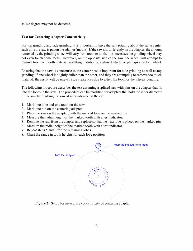
Figure 8. Measurement of side grinder angles relative to the saw center post.
Setting Side Grinder Angles
As with setting top and face grinder square, the center post will be used as the reference for allmeasurements because most centering adapters hold the saw square to the post. Even if the clampunder the tooth is square, it is not strong enough to twist the saw.
Figure 8 shows the basic layout for measuring side clearance angles. Figure 9 shows the steps withphotographs. A V-block is clamped to the centering post and its surfaces can be used for references.From these surfaces, angle gauges can be attached. A test indicator is mounted on the grinding headso that the tip runs on the angle gauge. If the grinder is set to the correct angle, the indicator readingwill not change as the grinding head is cycles in and out.
For side grinding with cup wheel an arrangement similar to that shown in Figure 7 is used.
Conclusions
Accurate alignment and setting of saw grinders is critical for accurate sawing, especially for thinsaws. Since the measurement of tooth angles is very difficult, a better method is to set the exactangle on the grinder. Until the protractors become more precise, external measurements arerequired. However, the alignment of these machines can be done easily and precisely with a fewinstruments.

8
Figure 9. Checking the alignment of the side grinder heads to the saw center post using a V-block and test indicator. The magnetic base is mounted on the head being tested.Measurements are taken as the heads are indexed in and out.
References
1. AcuSaw “Tooth Inspector”Unit 5, 9060 Shaughnessy St. Vancouver, B.C., V6P 6R92. Forintek “Video Tooth Inspector”. 2665 East Mall, Vancouver, B.C., V6T 1W53. Bonac, Thomas, 1982. Influence of Grinding Accuracy on the Deflection of Carbide Tipped
Circular Saws. Proceedings of the Seventh Wood Machining Seminar, Richmond California,October 18-20, 1982