Embed Size (px)
Citation preview
Alignment of the OpticsSpartan IR Camera for the SOAR Telescope
Dustin Baker & Edwin D. Loh
Department of Physics & AstronomyMichigan State University, East Lansing, MI 48824
[email protected] 517 355–9200 x2480
17 July 200313 October 2005 Realigned after focus test
4 April 2006 Installed 4 eye7 January 2008 Realigned after cleaning
23 May 2008 Realigned after focusing
Abstract
The requirements for alignment of the optics, the procedure for alignment, andinspection reports are described here.
1 Preliminaries
Figure 1 defines directions on the cryo-optical box, which holds the optics, and Figure 2is a schematic of the optics.
The global coordinate system is used in the mechanical design. In the global coordi-nate system, the origin is where the optical axis intersects the front surface of the window.The x-coordinate increases toward the right wall in Figure 1. The y-coordinate increasestoward the back wall; the z-axis, toward the top plate.
Alignment of the optics is done with mechanical metrology: the optics are placed andbolted accurately. There are two reasons for choosing this method. Optical alignment ofan off-axis aspheric mirror requires adjusting 5 parameters, which are three translationsof the vertex and two rotations of the axis. A sphere requires the position of the surfacein one dimension and two rotations of the axis. We found that minimizing the image sizedoes not determine which parameter to adjust. The second reason is that the optics arebolted down. Adjusting mechanisms, which risk loosening and long times for thermalequilibrium, are avoided.
Axsys Technologies fabricated the aluminum mirrors with precisely located pads andpin holes. Since the pads and holes were used to locate the optic during interferometric
1 PRELIMINARIES
testing (and machining and polishing), the offset between them and the mirror surface isknown precisely. Alignment means to position the pads and pin holes of each optic in theCOB.
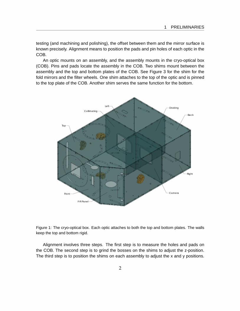
An optic mounts on an assembly, and the assembly mounts in the cryo-optical box(COB). Pins and pads locate the assembly in the COB. Two shims mount between theassembly and the top and bottom plates of the COB. See Figure 3 for the shim for thefold mirrors and the filter wheels. One shim attaches to the top of the optic and is pinnedto the top plate of the COB. Another shim serves the same function for the bottom.
Right
F-R Panel
Front
Back
Top
LeftDividing
Collimating
Camera
Figure 1: The cryo-optical box. Each optic attaches to both the top and bottom plates. The wallskeep the top and bottom rigid.
Alignment involves three steps. The first step is to measure the holes and pads onthe COB. The second step is to grind the bosses on the shims to adjust the z-position.The third step is to position the shims on each assembly to adjust the x and y positions.
2

1 PRELIMINARIES
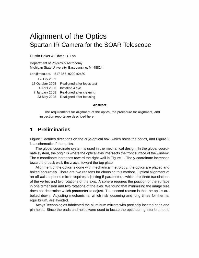
5 f12 Collimating Mirror5' f21 Collimating Mirror (inserted or removed)
4 N2 Cryostat
3 Mask Wheel (at telescope focus)
1 Entrance Window
2 Thermal Reflector
10' f/21 Focusing Mirror
10 f/12 Focusing Mirror (inserted or removed)
6 Fold Mirror #17 Big Filter Wheel
8 Little Filter Wheel (at pupil)
9 Fold Mirror #2
12 Field-flattening Lens (1 of 4)
13 Detector (1 of 4)
11 Pyramidal Mirror
A
C
D
DATE NAME
ENG APPR.
MFG APPR.
Q.A.
COMMENTS:SIZE
CDWG. NO. REV
WEIGHT: SHEET 1 OF 1SCALE: 1:3
Physics-Astronomy DepartmentMichigan State Univ, East Lansing MI
OPTICALSCHEMATIC
0-1
DESIGNED
DETAILED
04/22/06 E Loh
SPARTAN IR CAMERA [email protected] 2: Optical schematic. These parts require alignment: the mask assembly (3), the twocollimators (5 and 5’), the filter-fold assembly (6–9), the two camera mirrors (10 and 10’), and thedetector assembly (11-13).
3
1.1 Metrology of the mirrors 1 PRELIMINARIES
A faux COB with pins that mimic the pins in the real COB (Figure 3) holds the shim. Afine-pitched “nudger” shifts the assembly with respect to the shims, and then the shim isfastened with bolts.
Figure 3: Bottom left panel: the bottom shim for the fold-filter assembly. (The shim is shiny.) Topleft: detail showing the region of shim near the large filter wheel. Right panels: faux COB forpositioning the assembly.
1.1 Metrology of the mirrors
Our method of alignment by metrology requires that the relation between the surface ofthe mirror and mounting pads be known accurately.
We estimate that the tilt between the surface of the mirror and mounting pads issufficiently accurate. The pads are pinned to a master plate during turning on the latheand during polishing and testing with an interferometer. During polishing, a tilt of “a few
4
1.1 Metrology of the mirrors 1 PRELIMINARIES
waves” is ignored. A tilt of 3 waves over the diameter of the smallest mirror (100 mm) is0.019 mrad. This is a factor of 5 smaller than the tightest tolerance of tilt in Table 2.
We estimate that the location of the pads in the direction perpendicular to the axisof the mirror is sufficiently accurate. The position is fixed by pins. Assembly requires“pushing on the mirror in the direction away from the axis.1” We interpret that to meanthere is some looseness, and we assume that assembly is reproducible to 0.006 mm,which is half of the fit of the pins.
We estimate that the accuracy of the focal position is 0.01 mm. The mirror is testedwith a computer-generated hologram (CGH), which is mounted on a steel rail. The tem-perature of the room can change by 1 C, which moves the CGH and mirror radius by1.4× 10−5, the relative expansion between aluminum and steel. The change in radius is0.016–0.024 mm for the four mirrors.
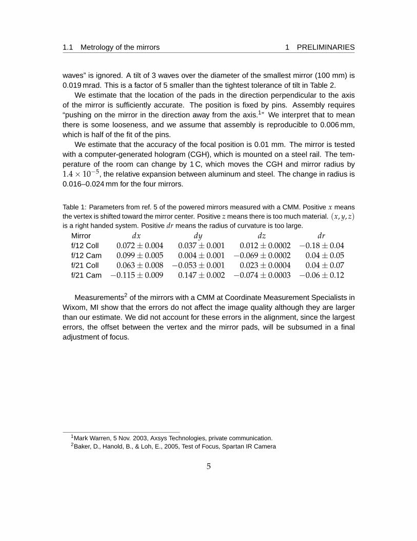
Table 1: Parameters from ref. 5 of the powered mirrors measured with a CMM. Positive x meansthe vertex is shifted toward the mirror center. Positive z means there is too much material. (x, y, z)is a right handed system. Positive dr means the radius of curvature is too large.
Mirror dx dy dz drf/12 Coll 0.072± 0.004 0.037± 0.001 0.012± 0.0002 −0.18± 0.04f/12 Cam 0.099± 0.005 0.004± 0.001 −0.069± 0.0002 0.04± 0.05f/21 Coll 0.063± 0.008 −0.053± 0.001 0.023± 0.0004 0.04± 0.07f/21 Cam −0.115± 0.009 0.147± 0.002 −0.074± 0.0003 −0.06± 0.12
Measurements2 of the mirrors with a CMM at Coordinate Measurement Specialists inWixom, MI show that the errors do not affect the image quality although they are largerthan our estimate. We did not account for these errors in the alignment, since the largesterrors, the offset between the vertex and the mirror pads, will be subsumed in a finaladjustment of focus.
1Mark Warren, 5 Nov. 2003, Axsys Technologies, private communication.2Baker, D., Hanold, B., & Loh, E., 2005, Test of Focus, Spartan IR Camera
5

2 MEASUREMENTS OF THE CRYO-OPTICAL BOX
2 Measurements of the cryo-optical box
The measurements of the COB3 are summarized here.A coordinate measuring machine (CMM) (DEA Diamond 01.02) was used for all mea-
surements. Its greatest error over the 1020×660×460-mm volume is 0.006 mm. Overshort distances, the error is smaller.
2.1 Pin locations
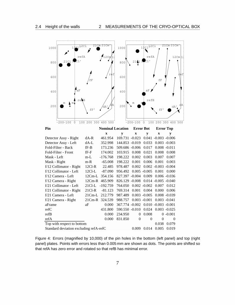
Pin holes locate the optics, and the table in Figure 4 lists their positions with respect toreference holes A and B. The nominal locations of the pin holes are given in the globalcoordinate system.
2.2 Deviation of the bottom plate from a plane
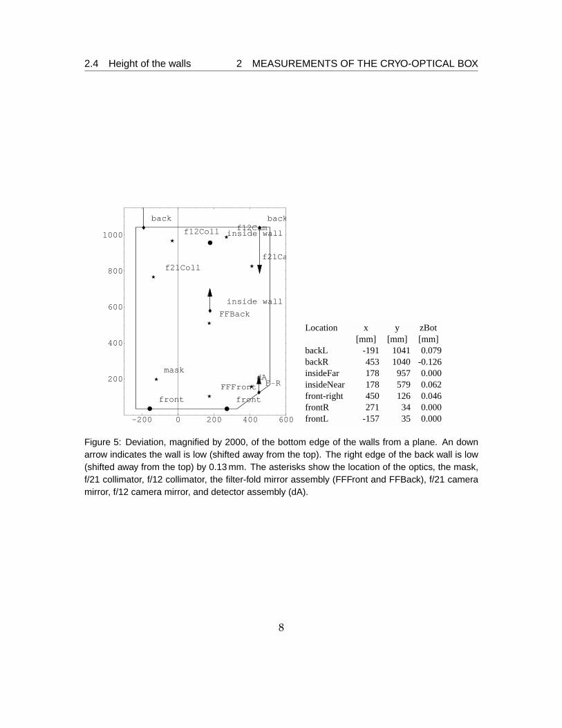
Since the top and bottom plates of the COB are thin (6 mm) and flexible, the walls fix theform of the plates. Three points, “frontL” and “frontR” in the front wall and “insideFar” individing wall, define the reference plane. All of the optics are centered on this plane.
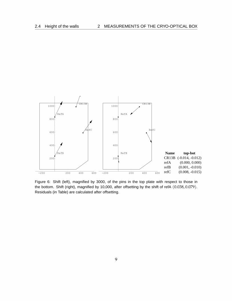
The deviation of the bottom plate from the reference plane is shown in Figure 6. Thestandard deviation is 0.063 mm. To first order, the back of the COB is twisted, and thestandard deviation is 0.037 mm with the twist removed.
2.3 Shift between the top and bottom plates
To determine the shift, the hole on the bottom plate is projected perpendicular to thereference plane of §2.2 to the top plate, which is 40 mm distant.
The location of reference hole A in the top is (0.038, 0.079) mm from the hole in thebottom (Figure 4).
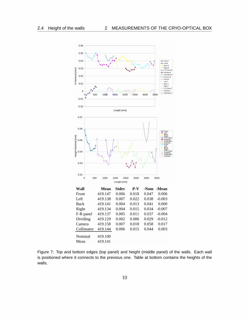
2.4 Height of the walls
The walls define the separation between the top and bottom plates. Measurements are inFigure 7. The walls are generally 0.010 mm lower in the middle. The walls were fabricatedto be 419.10 mm in height, but the actual mean is 419.141 mm. We adopt 419.141 mm tobe the target separation between the top and bottom plates.
3Samet, Biel, & Loh, 2003,Metrology of the Cryo-optical Box
6
2.4 Height of the walls 2 MEASUREMENTS OF THE CRYO-OPTICAL BOX
-200-100 0 100 200 300 400 500
200
400
600
800
1000
dAdA’
fF
fF’
m m’
12Cl12Cl’
12Cm 12
21Cl 21Cl’
21Cm 21Cm’
aF
ref
refB
refA
-200-100 0 100 200 300 400 500
200
400
600
800
1000
dAdA’
fF
fF’
m m’
12Cl12Cl’
12Cm 12
21Cl 21Cl’
21Cm 21Cm’
aF
ref
refB
refA
Pin Nominal Locationx y x y x y
Detector Assy - Right dA-R 461.954 169.731 -0.023 0.041 -0.003 -0.006Detector Assy - Left dA-L 352.998 144.853 -0.019 0.033 0.003 -0.003Fold-Filter - Back fF-B 173.236 509.686 -0.006 0.017 0.008 -0.011Fold-Filter - Front fF-F 174.002 103.915 0.008 0.021 0.008 0.008Mask - Left m-L -176.768 198.222 0.002 0.003 0.007 0.007Mask - Right m-R -65.008 198.222 0.001 0.006 0.001 0.003f/12 Collimator - Right 12Cl-R 22.485 978.487 0.002 0.002 -0.003 -0.004f/12 Collimator - Left 12Cl-L -87.090 956.492 0.005 -0.005 0.001 0.000f/12 Camera - Left 12Cm-L 354.156 827.397 -0.004 0.009 0.006 -0.036f/12 Camera - Right 12Cm-R 465.909 826.129 -0.008 0.014 -0.005 -0.040f/21 Collimator - Left 21Cl-L -192.759 764.050 0.002 -0.002 0.007 0.012f/21 Collimator - Right 21Cl-R -81.123 769.314 0.001 0.004 0.000 0.006f/21 Camera - Left 21Cm-L 212.779 987.489 0.003 -0.005 0.008 -0.039f/21 Camera - Right 21Cm-R 324.539 988.757 0.003 -0.001 0.003 -0.041aFrame aF 0.000 367.774 -0.002 0.010 -0.003 -0.001refC 431.800 590.550 -0.010 0.024 0.003 -0.025refB 0.000 234.950 0 0.008 0 -0.001refA 0.000 831.850 0 0 0 0Top with respect to bottom 0.038 0.079Standard deviation excluding refA-refC 0.009 0.014 0.005 0.019
Error Bot Error Top
Figure 4: Errors (magnified by 10,000) of the pin holes in the bottom (left panel) and top (rightpanel) plates. Points with errors less than 0.005 mm are shown as dots. The points are shifted sothat refA has zero error and rotated so that refB has minimal error.
7
2.4 Height of the walls 2 MEASUREMENTS OF THE CRYO-OPTICAL BOX
-200 0 200 400 600
200
400
600
800
1000
back back
inside wall
inside wall
F�R
frontfront
dA
FFBack
FFFront
mask
f12Coll
f21Caf21Coll
f12Cam
Location x y zBot[mm] [mm] [mm]
backL -191 1041 0.079backR 453 1040 -0.126insideFar 178 957 0.000insideNear 178 579 0.062front-right 450 126 0.046frontR 271 34 0.000frontL -157 35 0.000
Figure 5: Deviation, magnified by 2000, of the bottom edge of the walls from a plane. An downarrow indicates the wall is low (shifted away from the top). The right edge of the back wall is low(shifted away from the top) by 0.13 mm. The asterisks show the location of the optics, the mask,f/21 collimator, f/12 collimator, the filter-fold mirror assembly (FFFront and FFBack), f/21 cameramirror, f/12 camera mirror, and detector assembly (dA).
8
2.4 Height of the walls 2 MEASUREMENTS OF THE CRYO-OPTICAL BOX
-200 200 400 600
200
400
600
800
1000CR13B
RefA
RefB
RefC
-200 200 400 600
200
400
600
800
1000CR13B
RefA
RefB
RefC
Name top-botCR13B (-0.014, -0.012)refA (0.000, 0.000)refB (0.001, -0.010)refC (0.008, -0.015)
Figure 6: Shift (left), magnified by 3000, of the pins in the top plate with respect to those inthe bottom. Shift (right), magnified by 10,000, after offsetting by the shift of refA (0.038, 0.079).Residuals (in Table) are calculated after offsetting.
9
2.4 Height of the walls 2 MEASUREMENTS OF THE CRYO-OPTICAL BOX
-0.02
-0.01
0
0.01
0.02
0.03
0.04
0.05
0.06
0 500 1000 1500 2000 2500 3000 3500
Length [mm]
D-N
omin
al [m
m]
Front-TLeft-BBack-BRight-BF-R Panel-BDividing-BCollimator-BCamera-BFront-BLeft-TBack-TRight-TF-R Panel-TDividing-TCollimator-T
0.02
0.03
0.04
0.05
0.06
0.07
0 500 1000 1500 2000 2500 3000 3500Length [mm]
Hei
ght-N
omin
al [m
m]
FrontLeftBackRightF-R PanelDividingCollimatorCameraFrontLeftBackRightF-R PanelDividingCollimatorCamera
Wall Mean Stdev P-V -Nom -MeanFront 419.147 0.006 0.018 0.047 0.006Left 419.138 0.007 0.022 0.038 -0.003Back 419.141 0.004 0.013 0.041 0.000Right 419.134 0.004 0.015 0.034 -0.007F-R panel 419.137 0.005 0.011 0.037 -0.004Dividing 419.129 0.002 0.006 0.029 -0.012Camera 419.158 0.007 0.018 0.058 0.017Collimator 419.144 0.006 0.015 0.044 0.003
Nominal 419.100Mean 419.141
Figure 7: Top and bottom edges (top panel) and height (middle panel) of the walls. Each wallis positioned where it connects to the previous one. Table at bottom contains the heights of thewalls.
10
3 REQUIREMENTS FOR POSITIONING THE OPTICS
3 Requirements for positioning the optics
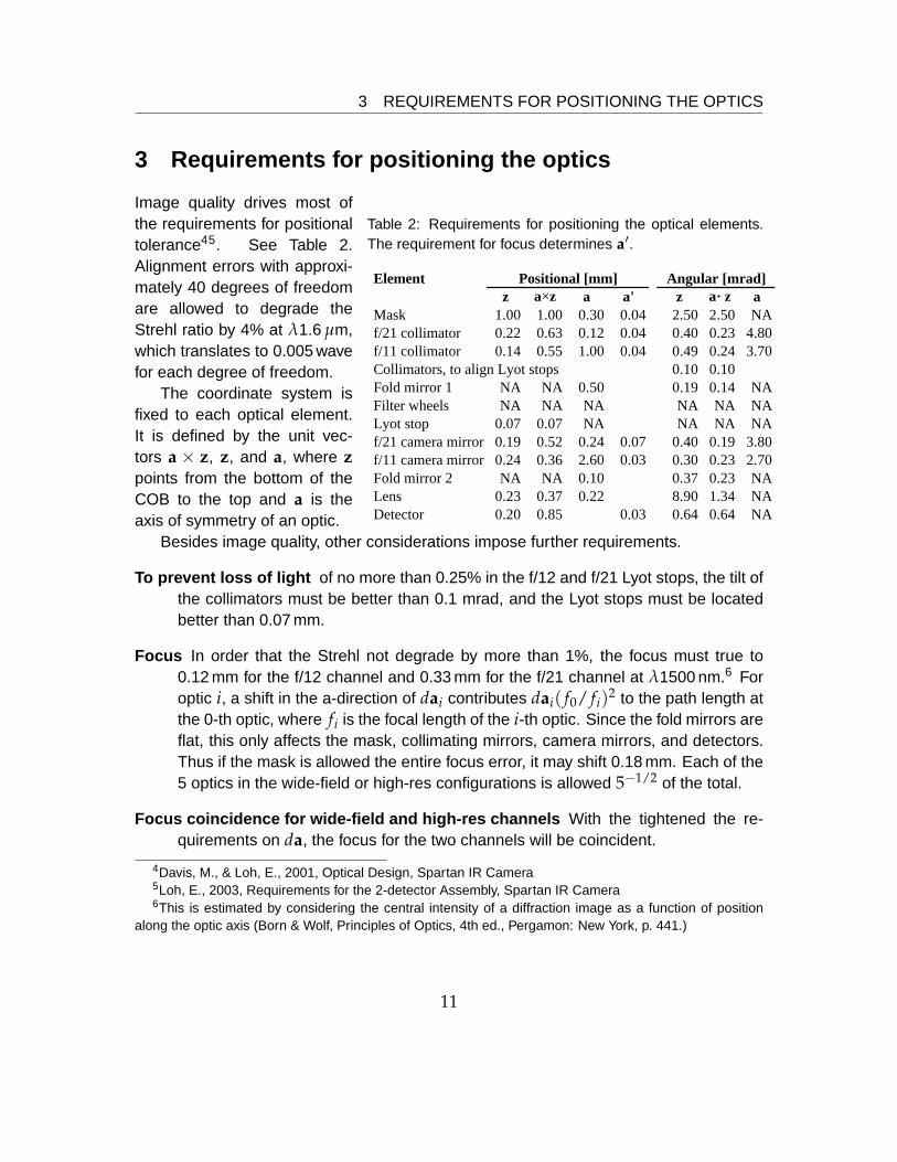
Table 2: Requirements for positioning the optical elements.The requirement for focus determines a′.
Elementz a×z a a' z a×z a
Mask 1.00 1.00 0.30 0.04 2.50 2.50 NAf/21 collimator 0.22 0.63 0.12 0.04 0.40 0.23 4.80f/11 collimator 0.14 0.55 1.00 0.04 0.49 0.24 3.70Collimators, to align Lyot stops 0.10 0.10Fold mirror 1 NA NA 0.50 0.19 0.14 NAFilter wheels NA NA NA NA NA NALyot stop 0.07 0.07 NA NA NA NAf/21 camera mirror 0.19 0.52 0.24 0.07 0.40 0.19 3.80f/11 camera mirror 0.24 0.36 2.60 0.03 0.30 0.23 2.70Fold mirror 2 NA NA 0.10 0.37 0.23 NALens 0.23 0.37 0.22 8.90 1.34 NADetector 0.20 0.85 0.03 0.64 0.64 NA
Angular [mrad]Positional [mm]
Image quality drives most ofthe requirements for positionaltolerance45. See Table 2.Alignment errors with approxi-mately 40 degrees of freedomare allowed to degrade theStrehl ratio by 4% at λ1.6 µm,which translates to 0.005 wavefor each degree of freedom.
The coordinate system isfixed to each optical element.It is defined by the unit vec-tors a × z, z, and a, where zpoints from the bottom of theCOB to the top and a is theaxis of symmetry of an optic.
Besides image quality, other considerations impose further requirements.
To prevent loss of light of no more than 0.25% in the f/12 and f/21 Lyot stops, the tilt ofthe collimators must be better than 0.1 mrad, and the Lyot stops must be locatedbetter than 0.07 mm.
Focus In order that the Strehl not degrade by more than 1%, the focus must true to0.12 mm for the f/12 channel and 0.33 mm for the f/21 channel at λ1500 nm.6 Foroptic i, a shift in the a-direction of dai contributes dai( f0/ fi)2 to the path length atthe 0-th optic, where fi is the focal length of the i-th optic. Since the fold mirrors areflat, this only affects the mask, collimating mirrors, camera mirrors, and detectors.Thus if the mask is allowed the entire focus error, it may shift 0.18 mm. Each of the5 optics in the wide-field or high-res configurations is allowed 5−1/2 of the total.
Focus coincidence for wide-field and high-res channels With the tightened the re-quirements on da, the focus for the two channels will be coincident.
4Davis, M., & Loh, E., 2001, Optical Design, Spartan IR Camera5Loh, E., 2003, Requirements for the 2-detector Assembly, Spartan IR Camera6This is estimated by considering the central intensity of a diffraction image as a function of position
along the optic axis (Born & Wolf, Principles of Optics, 4th ed., Pergamon: New York, p. 441.)
11
4 THICKNESS OF THE SHIMS
Focus across mask To preserve focus across the field, the a-axis must tilt by less than2.5 mrad.
4 Thickness of the shims
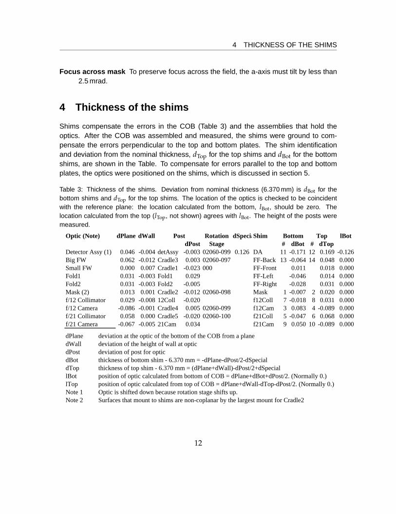
Shims compensate the errors in the COB (Table 3) and the assemblies that hold theoptics. After the COB was assembled and measured, the shims were ground to com-pensate the errors perpendicular to the top and bottom plates. The shim identificationand deviation from the nominal thickness, dTop for the top shims and dBot for the bottomshims, are shown in the Table. To compensate for errors parallel to the top and bottomplates, the optics were positioned on the shims, which is discussed in section 5.
Table 3: Thickness of the shims. Deviation from nominal thickness (6.370 mm) is dBot for thebottom shims and dTop for the top shims. The location of the optics is checked to be coincidentwith the reference plane: the location calculated from the bottom, lBot, should be zero. Thelocation calculated from the top (lTop, not shown) agrees with lBot. The height of the posts weremeasured.
Optic (Note) dPlane dWall Rotation dSpeciaShim lBotdPost Stage # dBot # dTop
Detector Assy (1) 0.046 -0.004 detAssy -0.003 02060-099 0.126 DA 11 -0.171 12 0.169 -0.126Big FW 0.062 -0.012 Cradle3 0.003 02060-097 FF-Back 13 -0.064 14 0.048 0.000Small FW 0.000 0.007 Cradle1 -0.023 000 FF-Front 0.011 0.018 0.000Fold1 0.031 -0.003 Fold1 0.029 FF-Left -0.046 0.014 0.000Fold2 0.031 -0.003 Fold2 -0.005 FF-Right -0.028 0.031 0.000Mask (2) 0.013 0.001 Cradle2 -0.012 02060-098 Mask 1 -0.007 2 0.020 0.000f/12 Collimator 0.029 -0.008 12Coll -0.020 f12Coll 7 -0.018 8 0.031 0.000f/12 Camera -0.086 -0.001 Cradle4 0.005 02060-099 f12Cam 3 0.083 4 -0.089 0.000f/21 Collimator 0.058 0.000 Cradle5 -0.020 02060-100 f21Coll 5 -0.047 6 0.068 0.000f/21 Camera -0.067 -0.005 21Cam 0.034 f21Cam 9 0.050 10 -0.089 0.000
dPlane deviation at the optic of the bottom of the COB from a planedWall deviation of the height of wall at opticdPost deviation of post for opticdBot thickness of bottom shim - 6.370 mm = -dPlane-dPost/2-dSpecialdTop thickness of top shim - 6.370 mm = (dPlane+dWall)-dPost/2+dSpeciallBot position of optic calculated from bottom of COB = dPlane+dBot+dPost/2. (Normally 0.)lTop position of optic calculated from top of COB = dPlane+dWall-dTop-dPost/2. (Normally 0.)Note 1 Optic is shifted down because rotation stage shifts up.Note 2 Surfaces that mount to shims are non-coplanar by the largest mount for Cradle2
Bottom TopPost
12
4 THICKNESS OF THE SHIMS
Twist of the Bottom of the COB The bottom of the COB was machined flat when it wasbolted inside-out on the walls, but it acquires non-flatness after reassembly with theoutside out. The deviation of the bottom plate from a plane, dPlane, is interpolatedfrom the measurements of the bottom (§2.2) at the walls that fix the bottom.
Height of Walls The walls fix the offset of the top and bottom plates. The deviation dWallfrom nominal at the optic is interpolated from the measurements of §2.4.
Height of Posts Several types of holders—cradles with rotation stages for the mask andfilter wheels, cradles with rotation stages and arms for the f/21 collimator and f/12camera mirrors, posts for the f/12 collimator, f/21 camera, and fold mirrors, and anassembly for the detector— support the optics, and these are all called posts here.
The heights of the posts were measured individually, and later with all of themplaced vertically on the bed of the coordinate-measuring machine as a sanitycheck. The earlier measurements define the height as the separation of the twoplanes that are defined by four points on the top and four points on the bottom. Inthe sanity check, the height is defined to be the distance between many points onthe top and many on the bottom. The ends of the posts are not flat, which wasdiscovered in the sanity check, and this makes the sanity check more reliable thanthe earlier measurements. The deviation dPost from the nominal of 406.400 mm istaken from the sanity check.
Special cases Most of the posts allow the optic to be moved to center it vertically, butthe three for the f/12 collimating mirror, f/21 camera mirror, and the 2-eyed de-tector assembly do not. For the two mirrors, the required tolerances (0.14 and0.19 mm, respectively) are looser than machining tolerances experienced on suchparts. Therefore the mirrors are assumed to be centered in the posts. The 2-eyed detector assembly, which is mounted on a rotation stage, should be movedby dSpecial from the center of the post.
For the 4-eyed detector assembly, positioning the legs that hold the detectors com-pensates for the error on the COB.
The bottom shim (between the bottom of the COB and the bottom of the post) mustcompensate for the non-flatness of the bottom of the COB and half of the height of thepost. Its thickness is
tBot = 6.350 + 0.020− dPlane − dPost/2− dSpecial.
The nominal thickness of the shim is 6.350 [0.25 in]. Because the walls are oversized by0.041, the shims are thicker by half. The term dSpecial is the thickness deviation of the
13

4 THICKNESS OF THE SHIMS
rotation stage for the detector assembly; it is 0 for all others. The top shim (between thetop of the COB and the top of the post) must compensate for the non-flatness of the topof the COB and half of the height of the post. Its thickness is
tTop = 6.350 + 0.020 + (dPlane + dWall)− dPost/2 + dSpecial.
The term in parenthesis is the non-flatness of the top of the COB.
14
5 INSTALLING THE OPTICS
5 Installing the optics
The positional error of the vertex of an optic is pm−pt, where pt is the target position andpm is the measured position. The rotational error of an optic is expressed as at × am,where at is the target axis of the optic and am is the measured axis. The direction ofat × am is the axis of the error, and its length is the rotation angle.
The coordinate system that is fixed to each optical element is defined by the unitvectors a × z, z, and a, where z points from the bottom of the COB to the top and a isthe axis of rotation of the optic.
Tightening the bolts must be done in a way that the part does not shift. (1) Tightenall of the bolts finger tight. (2) Tighten a bolt with an Allen wrench by rolling it betweenthe thumb and fingers. Tighten all of the bolts in the same way in sequence. Tightenopposite bolts in pairs. For example, with 4 bolts numbered 1–4 in clockwise order,tighten them in the order 1, 3, 2, and 4. (3) Tighten the bolts to 1/10 of the final torque inthe same sequence. (4) Tighten the bolts to 1/3 of the final torque in the same sequence.(5)Tighten the bolts to the final torque in the same sequence.
For fine movements, we use fine-pitch (320 µm/turn, 80 turn/in) nudgers (Figure 11).A rubber band maintains a constant force between the nudgers and the part. After movingthe shim and before measuring the pin holes on the shim, the bolts are tightened slightlybeyond finger tight, to prevent the shim from moving accidentally after the measurement.With the nudgers and rubber band, moving to a precision of 10 µm is routine.
5.1 Mask wheel
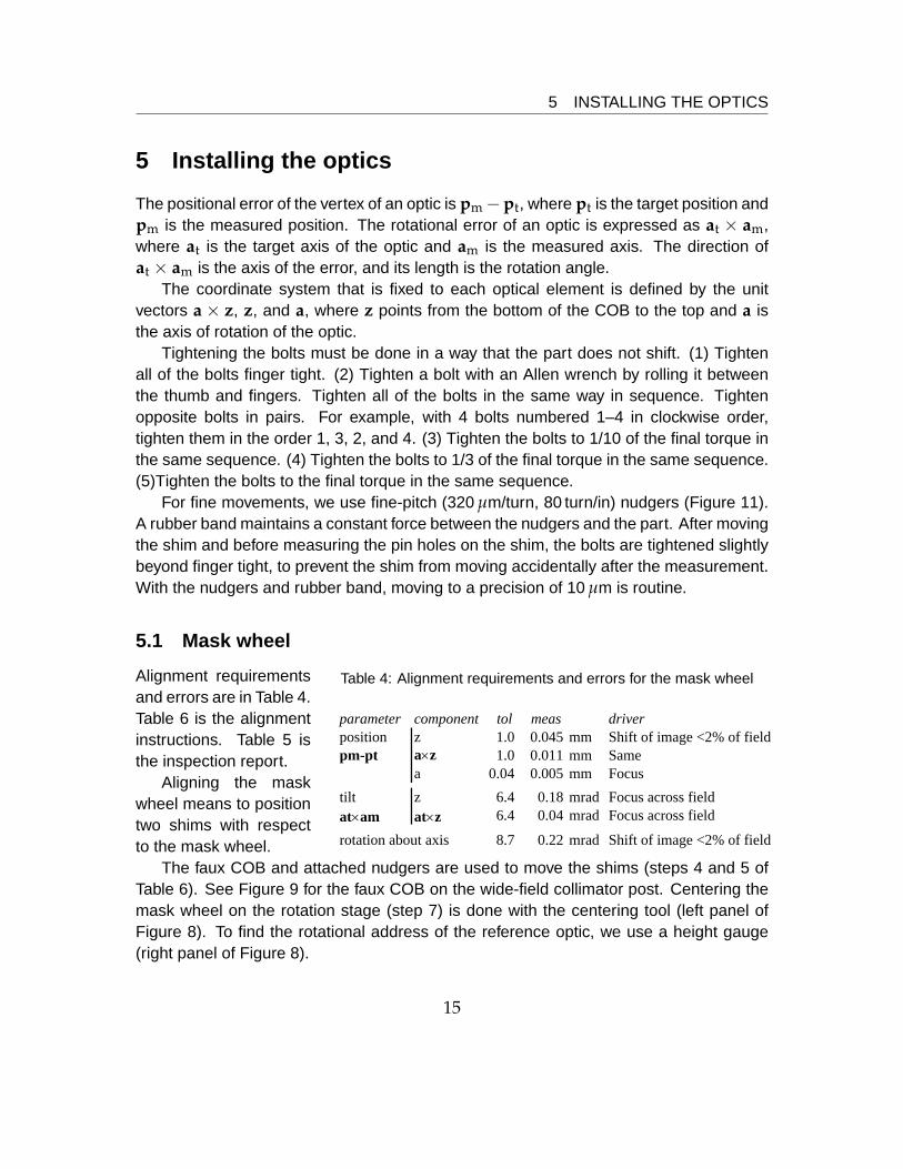
Table 4: Alignment requirements and errors for the mask wheel
parameter component tol meas driverposition z 1.0 0.045 mm Shift of image <2% of fieldpm-pt a×z 1.0 0.011 mm Same
a 0.04 0.005 mm Focustilt z 6.4 0.18 mrad Focus across fieldat×am at×z 6.4 0.04 mrad Focus across field
rotation about axis 8.7 0.22 mrad Shift of image <2% of field
Alignment requirementsand errors are in Table 4.Table 6 is the alignmentinstructions. Table 5 isthe inspection report.
Aligning the maskwheel means to positiontwo shims with respectto the mask wheel.
The faux COB and attached nudgers are used to move the shims (steps 4 and 5 ofTable 6). See Figure 9 for the faux COB on the wide-field collimator post. Centering themask wheel on the rotation stage (step 7) is done with the centering tool (left panel ofFigure 8). To find the rotational address of the reference optic, we use a height gauge(right panel of Figure 8).
15
5.1 Mask wheel 5 INSTALLING THE OPTICS
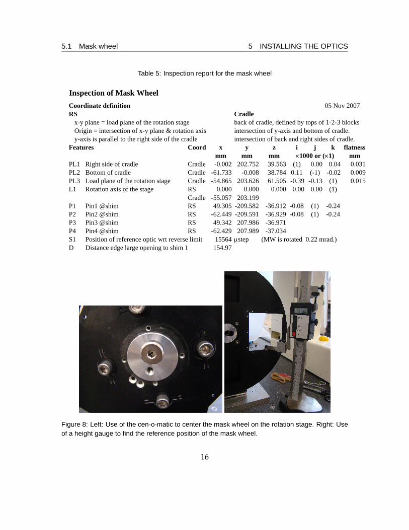
Table 5: Inspection report for the mask wheel
Inspection of Mask WheelCoordinate definitionRS Cradle
x-y plane = load plane of the rotation stage back of cradle, defined by tops of 1-2-3 blocksOrigin = intersection of x-y plane & rotation axis intersection of y-axis and bottom of cradle.y-axis is parallel to the right side of the cradle intersection of back and right sides of cradle.
Features Coord x y z i j k flatnessmm mm mm mm
PL1 Right side of cradle Cradle -0.002 202.752 39.563 (1) 0.00 0.04 0.031PL2 Bottom of cradle Cradle -61.733 -0.008 38.784 0.11 (-1) -0.02 0.009PL3 Load plane of the rotation stage Cradle -54.865 203.626 61.505 -0.39 -0.13 (1) 0.015L1 Rotation axis of the stage RS 0.000 0.000 0.000 0.00 0.00 (1)
Cradle -55.057 203.199P1 Pin1 @shim RS 49.305 -209.582 -36.912 -0.08 (1) -0.24P2 Pin2 @shim RS -62.449 -209.591 -36.929 -0.08 (1) -0.24P3 Pin3 @shim RS 49.342 207.986 -36.971P4 Pin4 @shim RS -62.429 207.989 -37.034S1 Position of reference optic wrt reverse limit 15564 μstep (MW is rotated 0.22 mrad.)D Distance edge large opening to shim 1 154.97
×1000 or (×1)
05 Nov 2007
Figure 8: Left: Use of the cen-o-matic to center the mask wheel on the rotation stage. Right: Useof a height gauge to find the reference position of the mask wheel.
16
5.1 Mask wheel 5 INSTALLING THE OPTICS
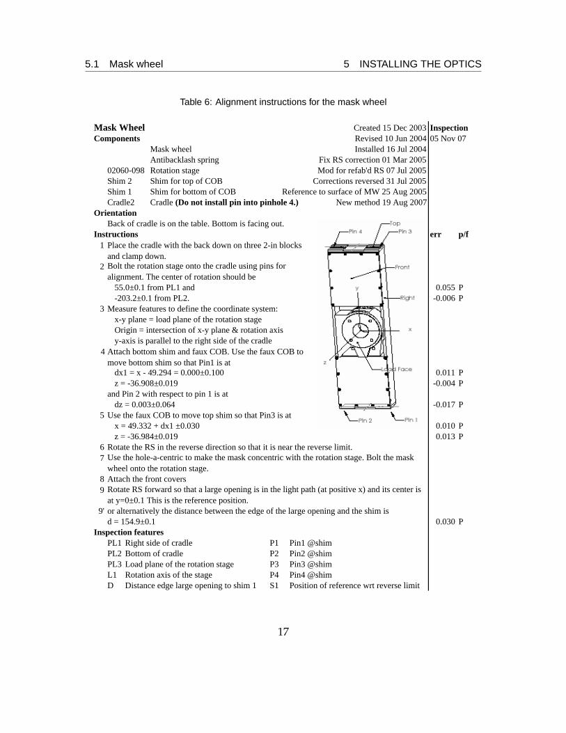
Table 6: Alignment instructions for the mask wheel
Mask Wheel Created 15 Dec 2003 InspectionComponents Revised 10 Jun 2004 05 Nov 07
Mask wheel Installed 16 Jul 2004Antibacklash spring Fix RS correction 01 Mar 2005Rotation stage Mod for refab'd RS 07 Jul 2005Shim for top of COB Corrections reversed 31 Jul 2005Shim for bottom of COB Reference to surface of MW 25 Aug 2005
Cradle2 Cradle (Do not install pin into pinhole 4.) New method 19 Aug 2007Orientation
Back of cradle is on the table. Bottom is facing out.Instructions err p/f
1
2
55.0±0.1 from PL1 and 0.055 P-203.2±0.1 from PL2. -0.006 P
3 Measure features to define the coordinate system:x-y plane = load plane of the rotation stageOrigin = intersection of x-y plane & rotation axisy-axis is parallel to the right side of the cradle
4
dx1 = x - 49.294 = 0.000±0.100 0.011 Pz = -36.908±0.019 -0.004 P
and Pin 2 with respect to pin 1 is atdz = 0.003±0.064 -0.017 P
5 Use the faux COB to move top shim so that Pin3 is atx = 49.332 + dx1 ±0.030 0.010 Pz = -36.984±0.019 0.013 P
6 Rotate the RS in the reverse direction so that it is near the reverse limit.7
8 Attach the front covers9
9' or alternatively the distance between the edge of the large opening and the shim isd = 154.9±0.1 0.030 P
Inspection featuresPL1 Right side of cradle P1 Pin1 @shimPL2 Bottom of cradle P2 Pin2 @shimPL3 Load plane of the rotation stage P3 Pin3 @shimL1 Rotation axis of the stage P4 Pin4 @shimD Distance edge large opening to shim 1 S1 Position of reference wrt reverse limit
Rotate RS forward so that a large opening is in the light path (at positive x) and its center is at y=0±0.1 This is the reference position.
Bolt the rotation stage onto the cradle using pins for alignment. The center of rotation should be
Use the hole-a-centric to make the mask concentric with the rotation stage. Bolt the mask wheel onto the rotation stage.
02060-098Shim 2Shim 1
Place the cradle with the back down on three 2-in blocks and clamp down.
Attach bottom shim and faux COB. Use the faux COB to move bottom shim so that Pin1 is at
17
5.2 Post for the wide-field collimator 5 INSTALLING THE OPTICS
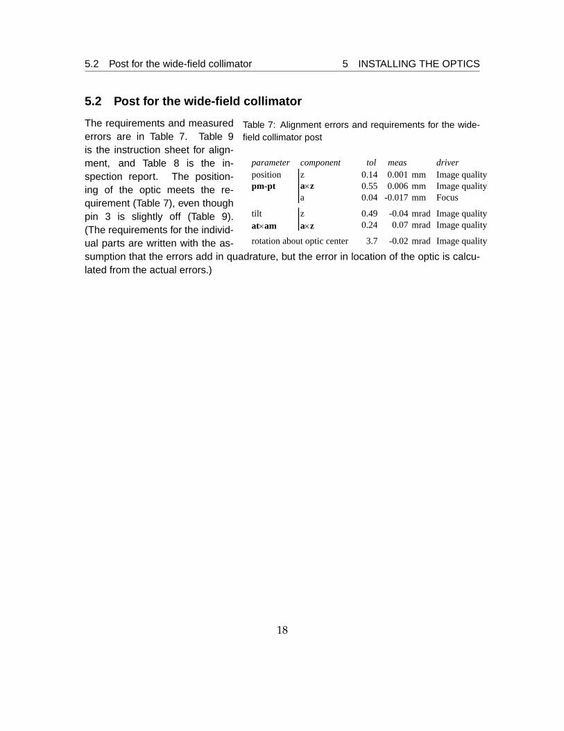
5.2 Post for the wide-field collimator
Table 7: Alignment errors and requirements for the wide-field collimator post
parameter component tol meas driverposition z 0.14 0.001 mm Image qualitypm-pt a×z 0.55 0.006 mm Image quality
a 0.04 -0.017 mm Focus
tilt z 0.49 -0.04 mrad Image qualityat×am a×z 0.24 0.07 mrad Image quality
rotation about optic center 3.7 -0.02 mrad Image quality
The requirements and measurederrors are in Table 7. Table 9is the instruction sheet for align-ment, and Table 8 is the in-spection report. The position-ing of the optic meets the re-quirement (Table 7), even thoughpin 3 is slightly off (Table 9).(The requirements for the individ-ual parts are written with the as-sumption that the errors add in quadrature, but the error in location of the optic is calcu-lated from the actual errors.)
18
5.2 Post for the wide-field collimator 5 INSTALLING THE OPTICS
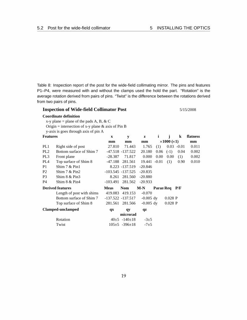
Table 8: Inspection report of the post for the wide-field collimating mirror. The pins and featuresP1–P4, were measured with and without the clamps used the hold the part. “Rotation” is theaverage rotation derived from pairs of pins. “Twist” is the difference between the rotations derivedfrom two pairs of pins.
Inspection of Wide-field Collimator PostCoordinate definition
x-y plane = plane of the pads A, B, & COrigin = intersection of x-y plane & axis of Pin By-axis is goes through axis of pin A
Features x y z i j k flatnessmm mm mm mm
PL1 Right side of post 27.810 71.443 1.765 (1) 0.03 -0.01 0.011PL2 Bottom surface of Shim 7 -47.518 -137.522 20.180 0.06 (-1) 0.04 0.002PL3 Front plane -28.387 71.817 0.000 0.00 0.00 (1) 0.002PL4 Top surface of Shim 8 -47.188 281.561 19.441 -0.01 (1) 0.90 0.010P1 Shim 7 & Pin1 8.223 -137.519 -20.846P2 Shim 7 & Pin2 -103.545 -137.525 -20.835P3 Shim 8 & Pin3 8.261 281.560 -20.880P4 Shim 8 & Pin4 -103.491 281.562 -20.933Derived features Meas Nom M-N ParamReq P/F
Length of post with shims 419.083 419.153 -0.070Bottom surface of Shim 7 -137.522 -137.517 -0.005 dy 0.028 PTop surface of Shim 8 281.561 281.566 -0.005 dy 0.028 P
Clamped-unclamped qx qy qz
Rotation 40±5 -140±18 -3±5Twist 105±5 -396±18 -7±5
5/15/2008
microrad
×1000 (×1)
19
5.2 Post for the wide-field collimator 5 INSTALLING THE OPTICS
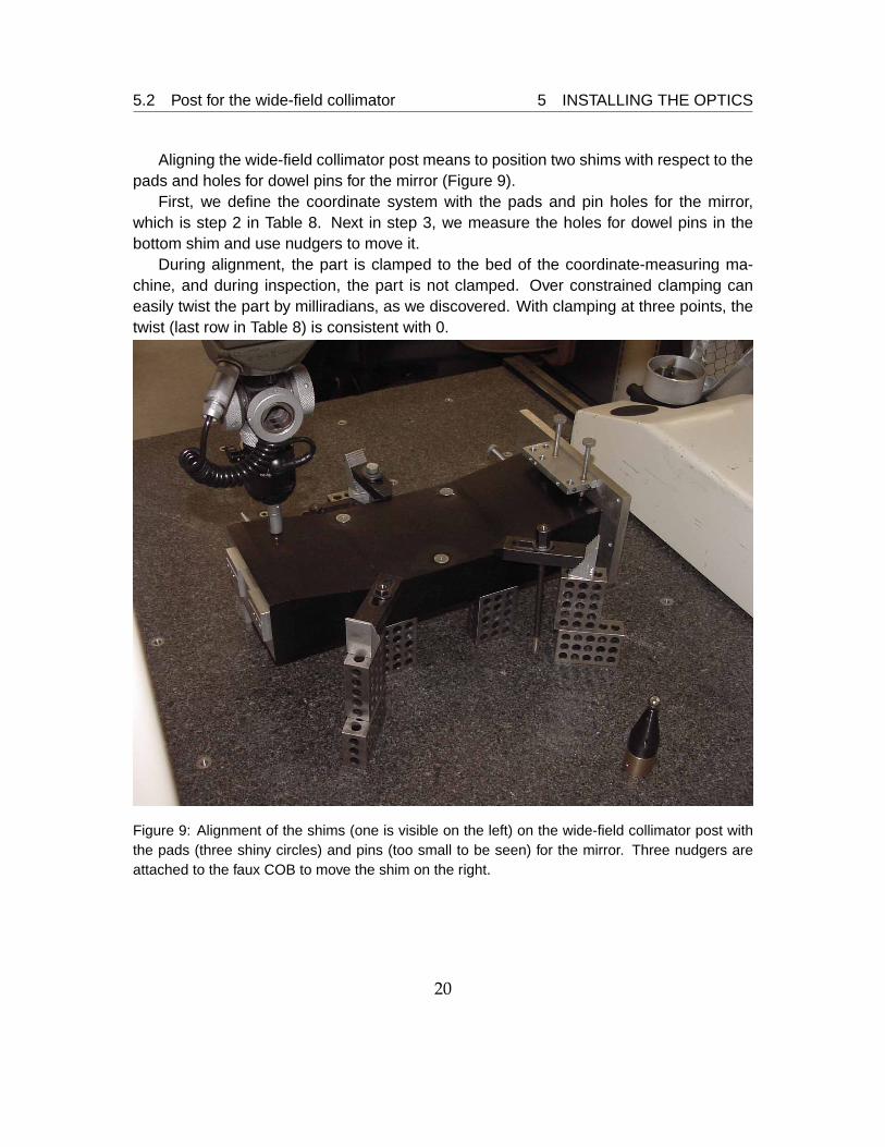
Aligning the wide-field collimator post means to position two shims with respect to thepads and holes for dowel pins for the mirror (Figure 9).
First, we define the coordinate system with the pads and pin holes for the mirror,which is step 2 in Table 8. Next in step 3, we measure the holes for dowel pins in thebottom shim and use nudgers to move it.
During alignment, the part is clamped to the bed of the coordinate-measuring ma-chine, and during inspection, the part is not clamped. Over constrained clamping caneasily twist the part by milliradians, as we discovered. With clamping at three points, thetwist (last row in Table 8) is consistent with 0.
Figure 9: Alignment of the shims (one is visible on the left) on the wide-field collimator post withthe pads (three shiny circles) and pins (too small to be seen) for the mirror. Three nudgers areattached to the faux COB to move the shim on the right.
20
5.2 Post for the wide-field collimator 5 INSTALLING THE OPTICS
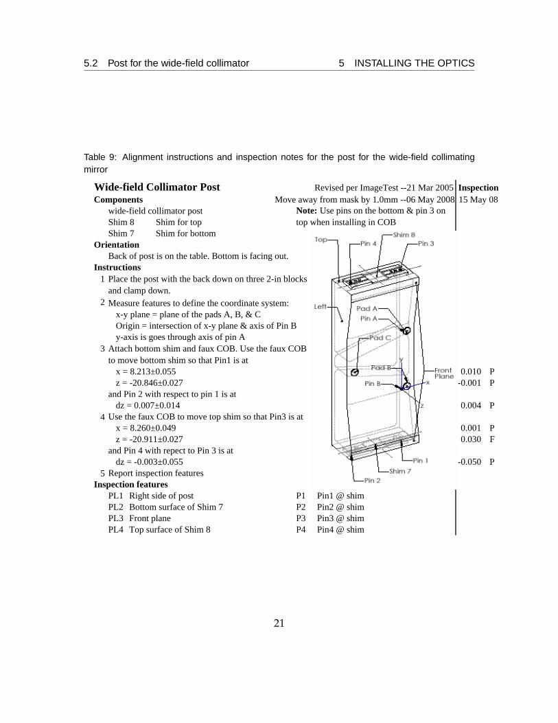
Table 9: Alignment instructions and inspection notes for the post for the wide-field collimatingmirror
Wide-field Collimator Post Revised per ImageTest --21 Mar 2005Components Move away from mask by 1.0mm --06 May 2008
wide-field collimator postShim 8 Shim for top
Shim for bottomOrientation
Back of post is on the table. Bottom is facing out.Instructions
1
2 Measure features to define the coordinate system:x-y plane = plane of the pads A, B, & COrigin = intersection of x-y plane & axis of Pin By-axis is goes through axis of pin A
3
x = 8.213±0.055 0.010 Pz = -20.846±0.027 -0.001 P
and Pin 2 with respect to pin 1 is atdz = 0.007±0.014 0.004 P
4 Use the faux COB to move top shim so that Pin3 is atx = 8.260±0.049 0.001 Pz = -20.911±0.027 0.030 F
and Pin 4 with repect to Pin 3 is atdz = -0.003±0.055 -0.050 P
5 Report inspection featuresInspection features
PL1 Right side of post P1 Pin1 @ shimPL2 Bottom surface of Shim 7 P2 Pin2 @ shimPL3 Front plane P3 Pin3 @ shimPL4 Top surface of Shim 8 P4 Pin4 @ shim
Attach bottom shim and faux COB. Use the faux COB to move bottom shim so that Pin1 is at
15 May 08Inspection
Shim 7
Place the post with the back down on three 2-in blocks and clamp down.
Note: Use pins on the bottom & pin 3 on top when installing in COB
21
5.3 Wide-field camera assembly 5 INSTALLING THE OPTICS
5.3 Wide-field camera assembly
Table 10: Requirements and errors for themirror arm of the wide-field camera assembly.
parameter component req measposition z 0.24 -0.17 mmpm-pt a×z 0.36 -0.017 mm
a 0.03 -0.030 mm
axis tilt z 0.30 0.38 mradat×am a×z 0.23 -0.09 mrad
rotation about optic center 2.7 0.01 mrad
The requirements and measured errors arein Table 10. Table 12 is the instruction sheetfor alignment, and Table 11 is the inspectionreport.
Aligning the wide-field camera mecha-nism means to position two shims with re-spect to the pads and holes for dowel pins forthe mirror. Two pins locate the rotation stagein the cradle, and the “cen-o-matic” centersthe mirror arm on the rotation stage. The re-maining degrees of freedom are the x and z position of pin 1, which is set in step 10 inTable 12, rotation of the bottom shim (step 10), the x and z positions of pin 3 (step 11),and the rotation angle of the mirror arm (step 8). The faux COB and attached nudgersare used to move the shims.
If the shims are not unbolted, the rotation stage may be removed and reinstalledwithout the use of a coordinate-measuring machine. A height gauge may be used to setthe rotation angle of the mirror arm. In that case, use step 8’ in Table 12.
The pin holes for the mirror are oversized by 0.035 and 0.045 mm, whereas the spec-ification for fabrication is +0.010
−0.000. A full step on the rotation stage is a rotation of 0.35 mradand a shift of the pins on the mirror arm of 0.05 mm.
22

5.3 Wide-field camera assembly 5 INSTALLING THE OPTICS
Table 11: Inspection report of the wide-field camera mirror assembly
Inspection of Wide-field Camera AssemblyC coordinate definitionx-y plane = plane of back of cradle. (Measure tops of 1-2-3 blocks.)y-axis = intersection of left of cradle & x-y planePoint on the bottom of cradle is on the x-z plane.AB coordinate definitiony-axis runs from Pin B toward Pin A parallel to the intersection of PL4 and PL1.x-y plane = plane of mirror pads
Features Coord x y z i j k flatnsmm mm mm μm
PL1 Left side of cradle AB 84.823 61.939 -63.964 (1) 0.00 0.19 7PL2 Bottom of surface of Shim 3 AB 144.808 -157.629 -79.030 0.13 (-1) 0.61 9PL3 Top of surface of shim 4 AB 144.106 261.477 -79.731 -0.21 (1) 0.26 9PL4 Pads of the arm AB 17.138 51.997 0.000 0.00 0.00 (1) 1P1 Pin 1 @ shim AB 200.877 -157.623 -79.963 -0.13 (1) -0.61P2 Pin 2 @ shim AB 89.127 -157.637 -79.950 -0.13 (1) -0.61P3 Pin 3 @ shim AB 200.915 261.489 -79.952 0.21 (-1) -0.26P4 Pin 4 @ shim AB 89.167 261.466 -79.888 0.21 (-1) -0.26
D Distance top of arm to bottom shim 266.76x y z
PinA C -84.713 255.208AB 0.110 104.032 0.000
PinB C -84.823 151.176
S1 Rev limit to "In" 155 microstepRev limit to forward limit 46266 microstep
02 Jan 2007
×1000 (×1)
23
5.3 Wide-field camera assembly 5 INSTALLING THE OPTICS
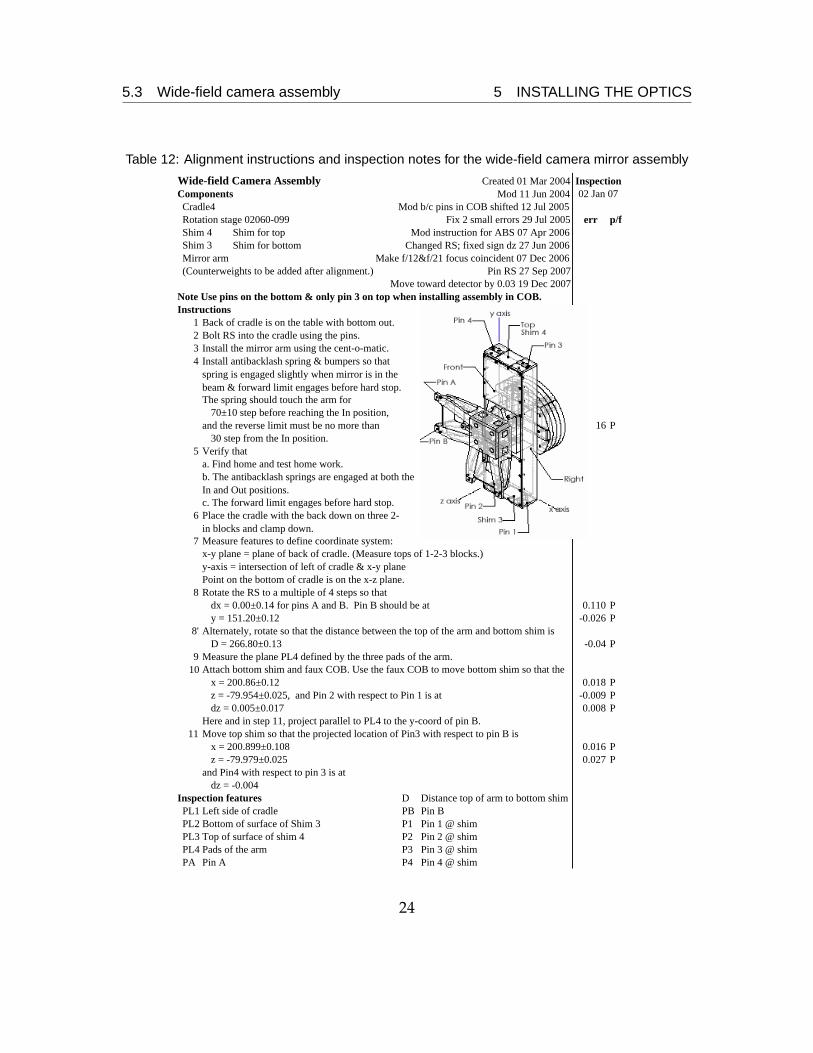
Table 12: Alignment instructions and inspection notes for the wide-field camera mirror assembly
Wide-field Camera Assembly Created 01 Mar 2004Components Mod 11 Jun 2004Cradle4 Mod b/c pins in COB shifted 12 Jul 2005Rotation stage 02060-099 Fix 2 small errors 29 Jul 2005 err p/fShim 4 Shim for top Mod instruction for ABS 07 Apr 2006
Shim for bottom Changed RS; fixed sign dz 27 Jun 2006Mirror arm Make f/12&f/21 focus coincident 07 Dec 2006(Counterweights to be added after alignment.) Pin RS 27 Sep 2007
Note Use pins on the bottom & only pin 3 on top when installing assembly in COB.Instructions
1 Back of cradle is on the table with bottom out.2 Bolt RS into the cradle using the pins.3 Install the mirror arm using the cent-o-matic.4
The spring should touch the arm for70±10 step before reaching the In position,
16 P30 step from the In position.
5 Verify thata. Find home and test home work.
c. The forward limit engages before hard stop.6
7 Measure features to define coordinate system:
y-axis = intersection of left of cradle & x-y planePoint on the bottom of cradle is on the x-z plane.
8 Rotate the RS to a multiple of 4 steps so thatdx = 0.00±0.14 for pins A and B. Pin B should be at 0.110 Py = 151.20±0.12 -0.026 P
8' Alternately, rotate so that the distance between the top of the arm and bottom shim isD = 266.80±0.13 -0.04 P
9 Measure the plane PL4 defined by the three pads of the arm.10
x = 200.86±0.12 0.018 Pz = -79.954±0.025, and Pin 2 with respect to Pin 1 is at -0.009 Pdz = 0.005±0.017 0.008 P
Here and in step 11, project parallel to PL4 to the y-coord of pin B.11 Move top shim so that the projected location of Pin3 with respect to pin B is
x = 200.899±0.108 0.016 Pz = -79.979±0.025 0.027 P
and Pin4 with respect to pin 3 is atdz = -0.004
Inspection features D Distance top of arm to bottom shimPL1 Left side of cradle PB Pin BPL2 Bottom of surface of Shim 3 P1 Pin 1 @ shimPL3 Top of surface of shim 4 P2 Pin 2 @ shimPL4 Pads of the arm P3 Pin 3 @ shimPA Pin A P4 Pin 4 @ shim
Attach bottom shim and faux COB. Use the faux COB to move bottom shim so that the
Install antibacklash spring & bumpers so that spring is engaged slightly when mirror is in the beam & forward limit engages before hard stop.
x-y plane = plane of back of cradle. (Measure tops of 1-2-3 blocks.)
Place the cradle with the back down on three 2-in blocks and clamp down.
b. The antibacklash springs are engaged at both the In and Out positions.
02 Jan 07Inspection
Shim 3
and the reverse limit must be no more than
Move toward detector by 0.03 19 Dec 2007
24
5.4 Filter-fold assembly 5 INSTALLING THE OPTICS
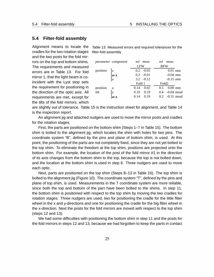
5.4 Filter-fold assembly
Table 13: Measured errors and required tolerances for thefilter-fold assembly
parameter component tol meas tol meas
position z 0.2 -0.05 0.01 mma×z 0.2 -0.01 -0.04 mma 3.2 -0.12 -0.15 mm
position a 0.14 0.02 0.5 0.00 mmtilt z 0.19 0.19 0.4 -0.04 mrad
a×z 0.14 0.19 0.2 -0.31 mrad
BFWLFW
Fold 1 Fold2
Alignment means to locate thecradles for the two rotation stagesand the two posts for the fold mir-rors on the top and bottom shims.The requirements and measurederrors are in Table 13. For foldmirror 1, that the light beam is co-incident with the Lyot stop setsthe requirement for positioning inthe direction of the optic axis. Allrequirements are met, except forthe tilts of the fold mirrors, whichare slightly out of tolerance. Table 15 is the instruction sheet for alignment, and Table 14is the inspection report.
An alignment jig and attached nudgers are used to move the mirror posts and cradlesfor the rotation stages.
First, the parts are positioned on the bottom shim (Steps 1–7 in Table 15). The bottomshim is bolted to the alignment jig, which locates the shim with holes for two pins. Thecoordinate system “B”, defined by the pins and plane of bottom shim, is used. At thispoint, the positioning of the parts are not completely fixed, since they are not yet bolted tothe top shim. To eliminate the freedom at the top shim, positions are projected onto thebottom shim. For example, the location of the post of the fold mirror #1 in the directionof its axis changes from the bottom shim to the top, because the top is not bolted down,and the location at the bottom shim is used in step 6. Three nudgers are used to moveeach optic.
Next, parts are positioned on the top shim (Steps 8–13 in Table 16). The top shim isbolted to the alignment jig (Figure 10). The coordinate system “T”, defined by the pins andplane of top shim, is used. Measurements in the T coordinate system are more reliable,since both the top and bottom of the part have been bolted to the shims. In step 11,the bottom shim is positioned with respect to the top shim by moving the two cradles forrotation stages. Three nudgers are used, two for positioning the cradle for the little filterwheel in the x and y-directions and one for positioning the cradle for the big filter wheel inthe x-direction. Next the posts for the fold mirrors are moved with respect to the top shim(steps 12 and 13).
We had some difficulties with positioning the bottom shim in step 11 and the posts forthe fold mirrors in steps 12 and 13, because we had forgotten to keep the parts in contact
25
5.4 Filter-fold assembly 5 INSTALLING THE OPTICS
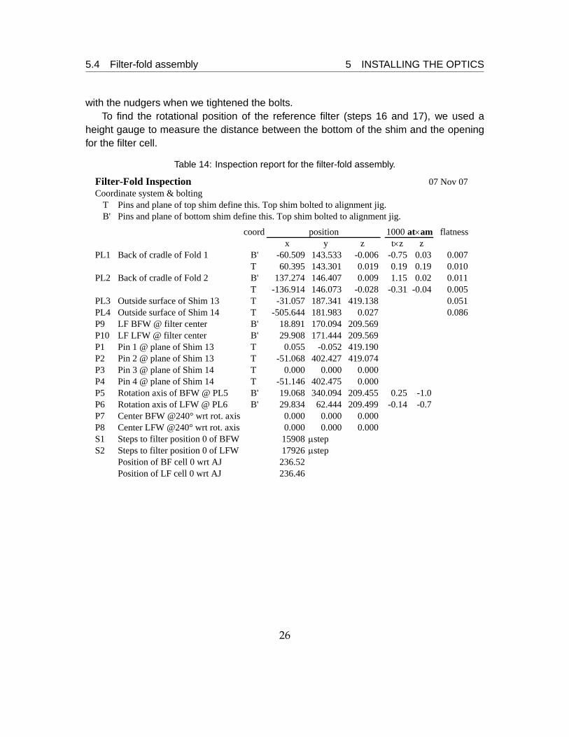
with the nudgers when we tightened the bolts.To find the rotational position of the reference filter (steps 16 and 17), we used a
height gauge to measure the distance between the bottom of the shim and the openingfor the filter cell.
Table 14: Inspection report for the filter-fold assembly.
Filter-Fold Inspection 07 Nov 07Coordinate system & bolting
T Pins and plane of top shim define this. Top shim bolted to alignment jig.B' Pins and plane of bottom shim define this. Top shim bolted to alignment jig.
coord flatnessx y z t×z z
PL1 Back of cradle of Fold 1 B' -60.509 143.533 -0.006 -0.75 0.03 0.007T 60.395 143.301 0.019 0.19 0.19 0.010
PL2 Back of cradle of Fold 2 B' 137.274 146.407 0.009 1.15 0.02 0.011T -136.914 146.073 -0.028 -0.31 -0.04 0.005
PL3 Outside surface of Shim 13 T -31.057 187.341 419.138 0.051PL4 Outside surface of Shim 14 T -505.644 181.983 0.027 0.086P9 LF BFW @ filter center B' 18.891 170.094 209.569P10 LF LFW @ filter center B' 29.908 171.444 209.569P1 Pin 1 @ plane of Shim 13 T 0.055 -0.052 419.190P2 Pin 2 @ plane of Shim 13 T -51.068 402.427 419.074P3 Pin 3 @ plane of Shim 14 T 0.000 0.000 0.000P4 Pin 4 @ plane of Shim 14 T -51.146 402.475 0.000P5 Rotation axis of BFW @ PL5 B' 19.068 340.094 209.455 0.25 -1.0P6 Rotation axis of LFW @ PL6 B' 29.834 62.444 209.499 -0.14 -0.7P7 Center BFW @240° wrt rot. axis 0.000 0.000 0.000P8 Center LFW @240° wrt rot. axis 0.000 0.000 0.000S1 Steps to filter position 0 of BFW 15908 μstepS2 Steps to filter position 0 of LFW 17926 μstep
Position of BF cell 0 wrt AJ 236.52Position of LF cell 0 wrt AJ 236.46
position 1000 at×am
26
5.4 Filter-fold assembly 5 INSTALLING THE OPTICS
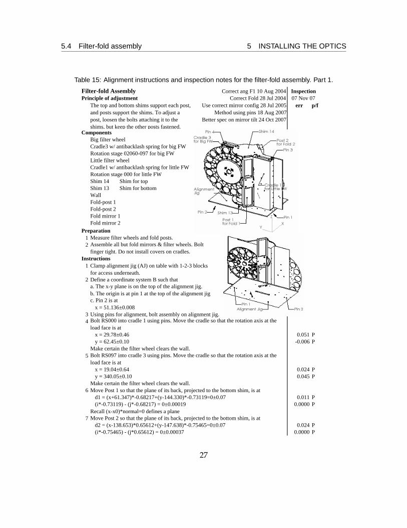
Table 15: Alignment instructions and inspection notes for the filter-fold assembly. Part 1.
Filter-fold Assembly Correct ang F1 10 Aug 2004Principle of adjustment Correct Fold 28 Jul 2004
err p/f
ComponentsBig filter wheelCradle3 w/ antibacklash spring for big FWRotation stage 02060-097 for big FWLittle filter wheelCradle1 w/ antibacklash spring for little FWRotation stage 000 for little FWShim 14 Shim for topShim 13 Shim for bottomWallFold-post 1Fold-post 2Fold mirror 1Fold mirror 2
Preparation12
Instructions1
2a. The x-y plane is on the top of the alignment jig.b. The origin is at pin 1 at the top of the alignment jigc. Pin 2 is at
x = 51.136±0.0083 Using pins for alignment, bolt assembly on alignment jig.4
x = 29.78±0.46 0.051 Py = 62.45±0.10 -0.006 P
Make certain the filter wheel clears the wall.5
x = 19.04±0.64 0.024 Py = 340.05±0.10 0.045 P
Make certain the filter wheel clears the wall.6 Move Post 1 so that the plane of its back, projected to the bottom shim, is at
d1 = (x+61.347)*-0.68217+(y-144.330)*-0.73119=0±0.07 0.011 P(i*-0.73119) - (j*-0.68217) = 0±0.00019 0.0000 P
Recall (x-x0)*normal=0 defines a plane7 Move Post 2 so that the plane of its back, projected to the bottom shim, is at
d2 = (x-138.653)*0.65612+(y-147.638)*-0.75465=0±0.07 0.024 P(i*-0.75465) - (j*0.65612) = 0±0.00037 0.0000 P
Measure filter wheels and fold posts.Assemble all but fold mirrors & filter wheels. Bolt finger tight. Do not install covers on cradles.
Clamp alignment jig (AJ) on table with 1-2-3 blocks for access underneath.Define a coordinate system B such that
Bolt RS000 into cradle 1 using pins. Move the cradle so that the rotation axis at the load face is at
Bolt RS097 into cradle 3 using pins. Move the cradle so that the rotation axis at the load face is at
Use correct mirror config 28 Jul 2005 Method using pins 18 Aug 2007
Better spec on mirror tilt 24 Oct 2007
Inspection07 Nov 07
The top and bottom shims support each post, and posts support the shims. To adjust a post, loosen the bolts attaching it to the shims, but keep the other posts fastened.
27
5.4 Filter-fold assembly 5 INSTALLING THE OPTICS
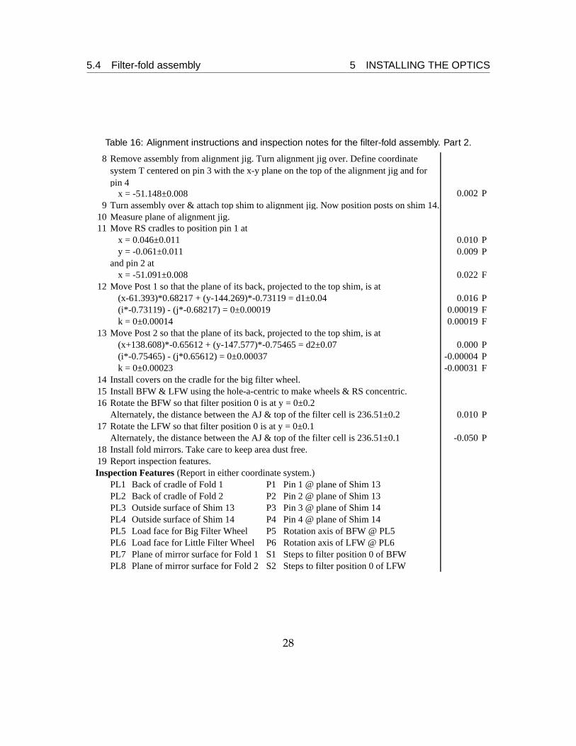
Table 16: Alignment instructions and inspection notes for the filter-fold assembly. Part 2.
8
x = -51.148±0.008 0.002 P9 Turn assembly over & attach top shim to alignment jig. Now position posts on shim 14.
10 Measure plane of alignment jig.11 Move RS cradles to position pin 1 at
x = 0.046±0.011 0.010 Py = -0.061±0.011 0.009 P
and pin 2 atx = -51.091±0.008 0.022 F
12 Move Post 1 so that the plane of its back, projected to the top shim, is at(x-61.393)*0.68217 + (y-144.269)*-0.73119 = d1±0.04 0.016 P(i*-0.73119) - (j*-0.68217) = 0±0.00019 0.00019 Fk = 0±0.00014 0.00019 F
13 Move Post 2 so that the plane of its back, projected to the top shim, is at(x+138.608)*-0.65612 + (y-147.577)*-0.75465 = d2±0.07 0.000 P(i*-0.75465) - (j*0.65612) = 0±0.00037 -0.00004 Pk = 0±0.00023 -0.00031 F
14 Install covers on the cradle for the big filter wheel.15 Install BFW & LFW using the hole-a-centric to make wheels & RS concentric.16 Rotate the BFW so that filter position 0 is at y = 0±0.2
Alternately, the distance between the AJ & top of the filter cell is 236.51±0.2 0.010 P17 Rotate the LFW so that filter position 0 is at y = 0±0.1
Alternately, the distance between the AJ & top of the filter cell is 236.51±0.1 -0.050 P18 Install fold mirrors. Take care to keep area dust free.19 Report inspection features.Inspection Features (Report in either coordinate system.)
PL1 Back of cradle of Fold 1 P1 Pin 1 @ plane of Shim 13PL2 Back of cradle of Fold 2 P2 Pin 2 @ plane of Shim 13PL3 Outside surface of Shim 13 P3 Pin 3 @ plane of Shim 14PL4 Outside surface of Shim 14 P4 Pin 4 @ plane of Shim 14PL5 Load face for Big Filter Wheel P5 Rotation axis of BFW @ PL5PL6 Load face for Little Filter Wheel P6 Rotation axis of LFW @ PL6PL7 Plane of mirror surface for Fold 1 S1 Steps to filter position 0 of BFWPL8 Plane of mirror surface for Fold 2 S2 Steps to filter position 0 of LFW
Remove assembly from alignment jig. Turn alignment jig over. Define coordinate system T centered on pin 3 with the x-y plane on the top of the alignment jig and for pin 4
28
5.4 Filter-fold assembly 5 INSTALLING THE OPTICS
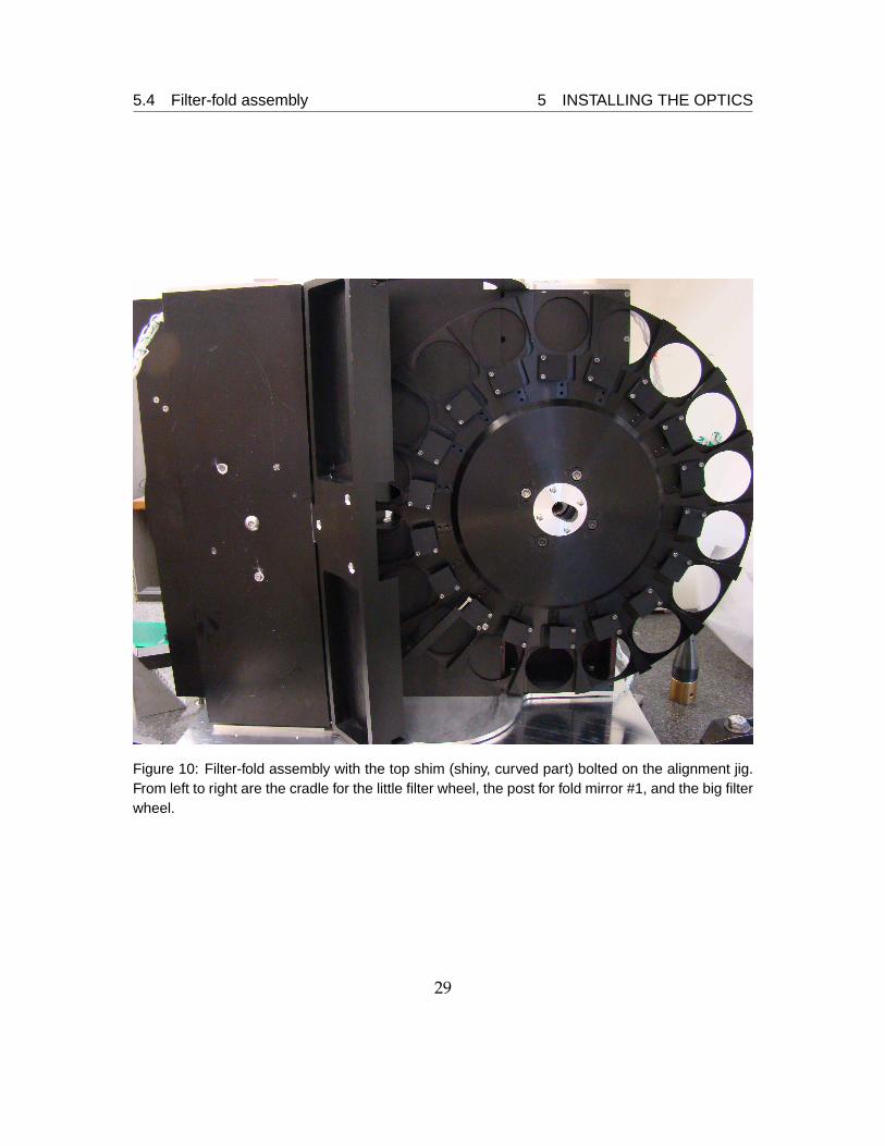
Figure 10: Filter-fold assembly with the top shim (shiny, curved part) bolted on the alignment jig.From left to right are the cradle for the little filter wheel, the post for fold mirror #1, and the big filterwheel.
29
5.5 Post for high-res camera mirror 5 INSTALLING THE OPTICS
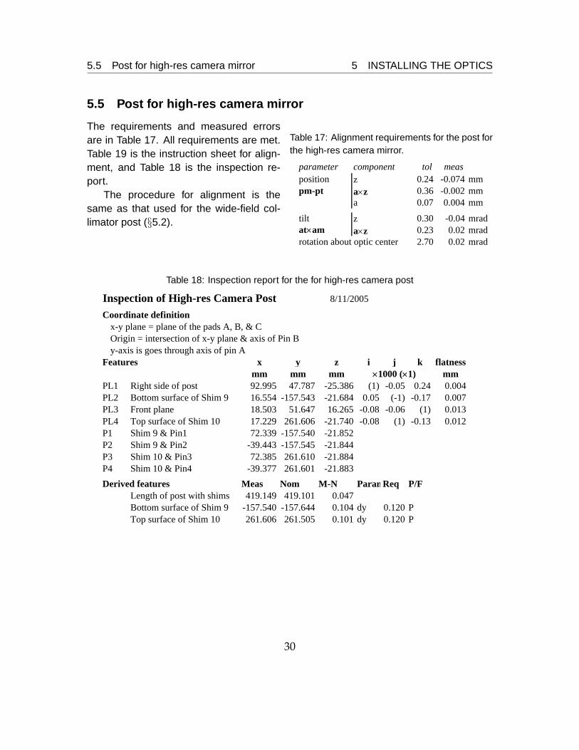
5.5 Post for high-res camera mirror
Table 17: Alignment requirements for the post forthe high-res camera mirror.
parameter component tol measposition z 0.24 -0.074 mmpm-pt a×z 0.36 -0.002 mm
a 0.07 0.004 mm
tilt z 0.30 -0.04 mradat×am a×z 0.23 0.02 mradrotation about optic center 2.70 0.02 mrad
The requirements and measured errorsare in Table 17. All requirements are met.Table 19 is the instruction sheet for align-ment, and Table 18 is the inspection re-port.
The procedure for alignment is thesame as that used for the wide-field col-limator post (§5.2).
Table 18: Inspection report for the for high-res camera post
Inspection of High-res Camera PostCoordinate definition
x-y plane = plane of the pads A, B, & COrigin = intersection of x-y plane & axis of Pin By-axis is goes through axis of pin A
Features x y z i j k flatnessmm mm mm mm
PL1 Right side of post 92.995 47.787 -25.386 (1) -0.05 0.24 0.004PL2 Bottom surface of Shim 9 16.554 -157.543 -21.684 0.05 (-1) -0.17 0.007PL3 Front plane 18.503 51.647 16.265 -0.08 -0.06 (1) 0.013PL4 Top surface of Shim 10 17.229 261.606 -21.740 -0.08 (1) -0.13 0.012P1 Shim 9 & Pin1 72.339 -157.540 -21.852P2 Shim 9 & Pin2 -39.443 -157.545 -21.844P3 Shim 10 & Pin3 72.385 261.610 -21.884P4 Shim 10 & Pin4 -39.377 261.601 -21.883Derived features Meas Nom M-N ParamReq P/F
Length of post with shims 419.149 419.101 0.047Bottom surface of Shim 9 -157.540 -157.644 0.104 dy 0.120 PTop surface of Shim 10 261.606 261.505 0.101 dy 0.120 P
×1000 (×1)
8/11/2005
30
5.5 Post for high-res camera mirror 5 INSTALLING THE OPTICS
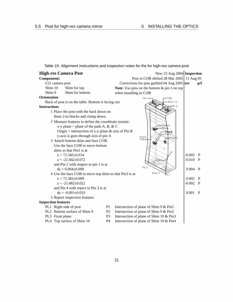
Table 19: Alignment instructions and inspection notes for the for high-res camera post
High-res Camera Post New 23 Aug 2004Components Pins in COB shifted 28 Mar 2005
f/21 camera post Corrections for pins garbled 04 Aug 2005 err p/fShim 10 Shim for top
Shim for bottomOrientation
Back of post is on the table. Bottom is facing out.Instructions
1
2 Measure features to define the coordinate system:x-y plane = plane of the pads A, B, & COrigin = intersection of x-y plane & axis of Pin By-axis is goes through axis of pin A
3
x = 72.345±0.014 -0.005 Pz = -21.842±0.072 -0.010 P
and Pin 2 with respect to pin 1 is atdz = 0.004±0.008 0.004 P
4 Use the faux COB to move top shim so that Pin3 is atx = 72.383±0.009 0.002 Pz = -21.882±0.022 -0.002 P
and Pin 4 with repect to Pin 3 is atdz = -0.001±0.033 0.001 P
5 Report inspection featuresInspection features
PL1 Right side of post P1 Intersection of plane of Shim 9 & Pin1PL2 Bottom surface of Shim 9 P2 Intersection of plane of Shim 9 & Pin2PL3 Front plane P3 Intersection of plane of Shim 10 & Pin3PL4 Top surface of Shim 10 P4 Intersection of plane of Shim 10 & Pin4
11 Aug 05Inspection
Attach bottom shim and faux COB. Use the faux COB to move bottom shim so that Pin1 is at
Place the post with the back down on three 2-in blocks and clamp down.
Shim 9Note: Use pins on the bottom & pin 3 on top when installing in COB
31

5.6 High-res collimating assembly 5 INSTALLING THE OPTICS
5.6 High-res collimating assembly
Table 20: Measured errors and required toler-ances for the arm of the high-res collimator as-sembly.
parameter component tol measposition z 0.22 -0.19 mm
pm-pt a×z 0.63 -0.02 mma 0.04 0.11 mm
tilt of axis z 0.40 0.17 mradat×am a×z 0.23 -0.04 mrad
rotation about optic center 4.80 -3.1 mrad
The requirements and measured errorsare in Table 20. Table 22 is the instruc-tion sheet for alignment, and Table 21 isthe inspection report. The optic is 0.11 mmfarther from the window than the require-ment.
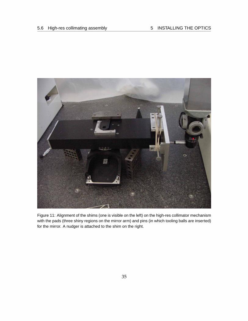
Aligning the high-res collimator meansto position two shims with respect to thepads and holes for dowel pins for the mir-ror (Figure 11). Two pins locate the rota-tion stage in the cradle, and the “cen-o-matic” centers the mirror arm on the rota-tion stage. The remaining degrees of freedom are the x and z position of pin 1, which isset in step 9 in Table 22, rotation of the bottom shim (step 9), the x and z positions of pin3 (step 10), and the rotation angle of the mirror arm (step 7).
Fine-pitched nudgers are used in steps 9 and 10 to move the shims. A rubber bandmaintains a constant force between the nudgers and the cradle.
If the shims are not unbolted, the rotation stage may be removed and reinstalledwithout the use of a coordinate-measuring machine. A height gauge may be used to setthe rotation angle of the mirror arm (Figure 12). In that case, use step 7’ in Table 22.
32
5.6 High-res collimating assembly 5 INSTALLING THE OPTICS
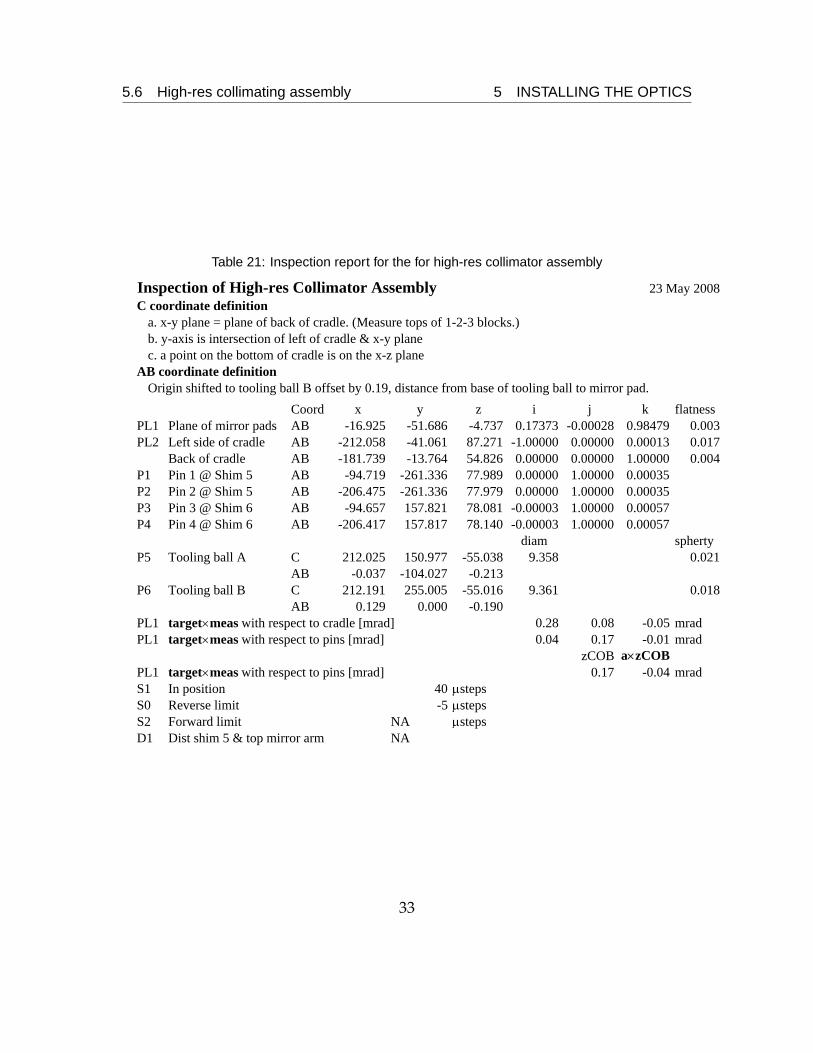
Table 21: Inspection report for the for high-res collimator assembly
Inspection of High-res Collimator Assembly 23 May 2008C coordinate definition
a. x-y plane = plane of back of cradle. (Measure tops of 1-2-3 blocks.)b. y-axis is intersection of left of cradle & x-y planec. a point on the bottom of cradle is on the x-z plane
AB coordinate definitionOrigin shifted to tooling ball B offset by 0.19, distance from base of tooling ball to mirror pad.
Coord x y z i j k flatnessPL1 Plane of mirror pads AB -16.925 -51.686 -4.737 0.17373 -0.00028 0.98479 0.003PL2 Left side of cradle AB -212.058 -41.061 87.271 -1.00000 0.00000 0.00013 0.017
Back of cradle AB -181.739 -13.764 54.826 0.00000 0.00000 1.00000 0.004P1 Pin 1 @ Shim 5 AB -94.719 -261.336 77.989 0.00000 1.00000 0.00035P2 Pin 2 @ Shim 5 AB -206.475 -261.336 77.979 0.00000 1.00000 0.00035P3 Pin 3 @ Shim 6 AB -94.657 157.821 78.081 -0.00003 1.00000 0.00057P4 Pin 4 @ Shim 6 AB -206.417 157.817 78.140 -0.00003 1.00000 0.00057
diam sphertyP5 Tooling ball A C 212.025 150.977 -55.038 9.358 0.021
AB -0.037 -104.027 -0.213P6 Tooling ball B C 212.191 255.005 -55.016 9.361 0.018
AB 0.129 0.000 -0.190PL1 target×meas with respect to cradle [mrad] 0.28 0.08 -0.05 mradPL1 target×meas with respect to pins [mrad] 0.04 0.17 -0.01 mrad
zCOB a×zCOBPL1 target×meas with respect to pins [mrad] 0.17 -0.04 mradS1 In position 40 μstepsS0 Reverse limit -5 μstepsS2 Forward limit NA μstepsD1 Dist shim 5 & top mirror arm NA
33
5.6 High-res collimating assembly 5 INSTALLING THE OPTICS
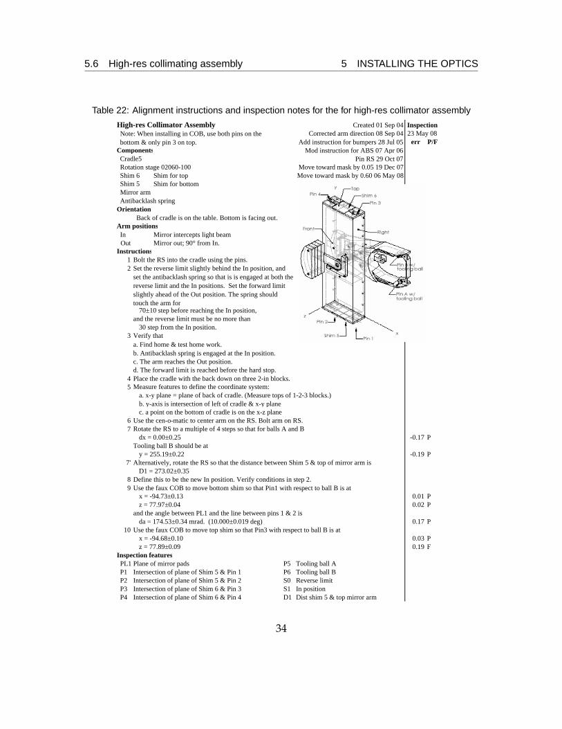
Table 22: Alignment instructions and inspection notes for the for high-res collimator assembly
High-res Collimator Assembly Created 01 Sep 04Corrected arm direction 08 Sep 04
Add instruction for bumpers 28 Jul 05 err P/FComponents Mod instruction for ABS 07 Apr 06Cradle5 Pin RS 29 Oct 07Rotation stage 02060-100 Move toward mask by 0.05 19 Dec 07Shim 6 Shim for top Move toward mask by 0.60 06 May 08
Shim for bottom
Antibacklash springOrientation
Arm positionsIn Mirror intercepts light beamOut Mirror out; 90° from In.
Instructions1 Bolt the RS into the cradle using the pins.2
70±10 step before reaching the In position,and the reverse limit must be no more than
30 step from the In position.3 Verify that
a. Find home & test home work.b. Antibacklash spring is engaged at the In position.c. The arm reaches the Out position.d. The forward limit is reached before the hard stop.
45
a. x-y plane = plane of back of cradle. (Measure tops of 1-2-3 blocks.)b. y-axis is intersection of left of cradle & x-y planec. a point on the bottom of cradle is on the x-z plane
6 Use the cen-o-matic to center arm on the RS. Bolt arm on RS.7
dx = 0.00±0.25 -0.17 PTooling ball B should be at
y = 255.19±0.22 -0.19 P7' Alternatively, rotate the RS so that the distance between Shim 5 & top of mirror arm is
D1 = 273.02±0.358 Define this to be the new In position. Verify conditions in step 2.9
x = -94.73±0.13 0.01 Pz = 77.97±0.04 0.02 P
and the angle between PL1 and the line between pins 1 & 2 isda = 174.53±0.34 mrad. (10.000±0.019 deg) 0.17 P
10 Use the faux COB to move top shim so that Pin3 with respect to ball B is atx = -94.68±0.10 0.03 Pz = 77.89±0.09 0.19 F
Inspection featuresPL1 Plane of mirror pads P5 Tooling ball AP1 Intersection of plane of Shim 5 & Pin 1 P6 Tooling ball BP2 Intersection of plane of Shim 5 & Pin 2 S0 Reverse limitP3 Intersection of plane of Shim 6 & Pin 3 S1 In positionP4 Intersection of plane of Shim 6 & Pin 4 D1 Dist shim 5 & top mirror arm
Inspection
Use the faux COB to move bottom shim so that Pin1 with respect to ball B is at
Shim 5
23 May 08
Rotate the RS to a multiple of 4 steps so that for balls A and B
Measure features to define the coordinate system:Place the cradle with the back down on three 2-in blocks.
Set the reverse limit slightly behind the In position, and set the antibacklash spring so that is is engaged at both the reverse limit and the In positions. Set the forward limit slightly ahead of the Out position. The spring should touch the arm for
Back of cradle is on the table. Bottom is facing out.
Note: When installing in COB, use both pins on the bottom & only pin 3 on top.
Mirror arm
34
5.6 High-res collimating assembly 5 INSTALLING THE OPTICS
Figure 11: Alignment of the shims (one is visible on the left) on the high-res collimator mechanismwith the pads (three shiny regions on the mirror arm) and pins (in which tooling balls are inserted)for the mirror. A nudger is attached to the shim on the right.
35

5.6 High-res collimating assembly 5 INSTALLING THE OPTICS
Figure 12: Use of a height gauge to set the rotation of the mirror arm for the high-res collimator
36
5.7 Four eye 5 INSTALLING THE OPTICS
5.7 Four eye
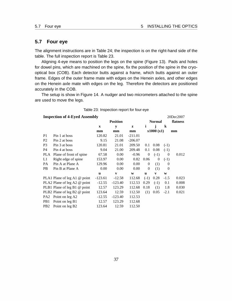
The alignment instructions are in Table 24; the inspection is on the right-hand side of thetable. The full inspection report is Table 23.
Aligning 4-eye means to position the legs on the spine (Figure 13). Pads and holesfor dowel pins, which are machined on the spine, fix the position of the spine in the cryo-optical box (COB). Each detector butts against a frame, which butts against an outerframe. Edges of the outer frame mate with edges on the Henein axles, and other edgeson the Henein axle mate with edges on the leg. Therefore the detectors are positionedaccurately in the COB.
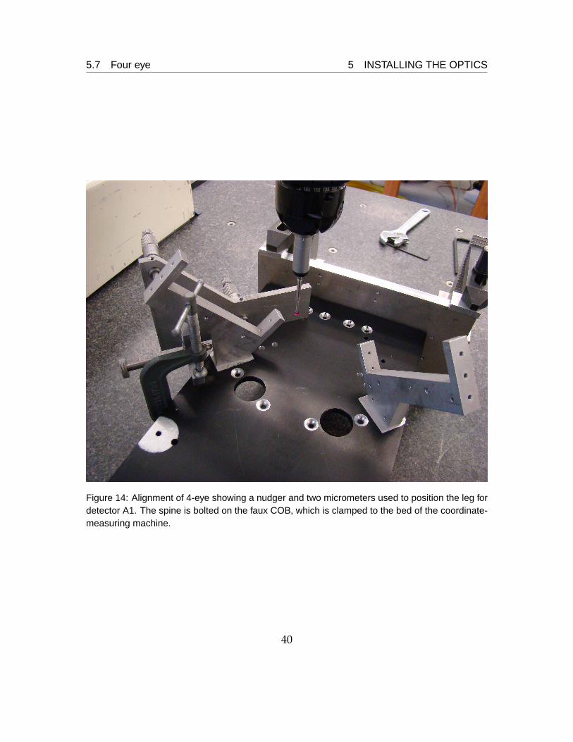
The setup is show in Figure 14. A nudger and two micrometers attached to the spineare used to move the legs.
Table 23: Inspection report for four-eye
Inspection of 4-Eyed Assembly 20Dec2007flatness
x y z i j kmm mm mm mm
P1 Pin 1 at boss 120.82 21.01 -211.01P2 Pin 2 at boss 9.15 21.08 -206.07P3 Pin 3 at boss 120.81 21.01 209.50 0.1 0.08 (-1)P4 Pin 4 at boss 9.04 21.00 209.48 0.1 0.08 (-1)PLA Plane of front of spine 67.58 0.00 -0.96 0 (-1) 0 0.012L1 Right edge of spine 153.97 0.00 0.82 0.06 0 (-1)PA Pin A at Plane A 129.96 0.00 0.00 0 (1) 0PB Pin B at Plane A 0.00 0.00 0.00 0 (1) 0
u v w u v wPLA1 Plane of leg A1 @ point -123.61 -12.58 112.68 (-1) 0.28 -1.5 0.023PLA2 Plane of leg A2 @ point -12.55 -123.40 112.53 0.29 (-1) 0.1 0.008PLB1 Plane of leg B1 @ point 12.57 123.29 112.68 0.18 (1) 1.8 0.030PLB2 Plane of leg B2 @ point 123.64 12.59 112.50 (1) 0.05 -2.1 0.021PA2 Point on leg A2 -12.55 -123.40 112.53PB1 Point on leg B1 12.57 123.29 112.68PB2 Point on leg B2 123.64 12.59 112.50
x1000 (x1)
NormalPosition
37
5.7 Four eye 5 INSTALLING THE OPTICS
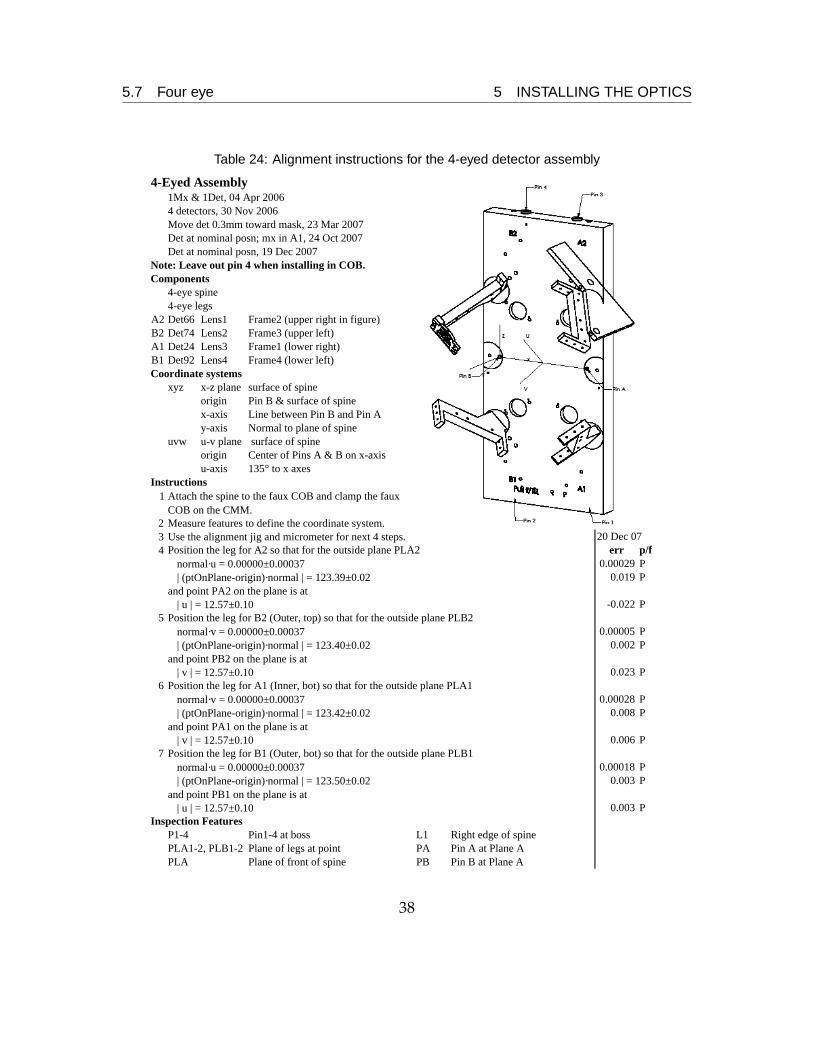
Table 24: Alignment instructions for the 4-eyed detector assembly
4-Eyed Assembly1Mx & 1Det, 04 Apr 20064 detectors, 30 Nov 2006Move det 0.3mm toward mask, 23 Mar 2007Det at nominal posn; mx in A1, 24 Oct 2007Det at nominal posn, 19 Dec 2007
Note: Leave out pin 4 when installing in COB.Components
4-eye spine4-eye legs
A2 Det66 Lens1 Frame2 (upper right in figure)B2 Det74 Lens2 Frame3 (upper left)A1 Det24 Lens3 Frame1 (lower right)B1 Det92 Lens4 Frame4 (lower left)Coordinate systems
xyz x-z plane surface of spineorigin Pin B & surface of spinex-axis Line between Pin B and Pin Ay-axis Normal to plane of spine
uvw u-v plane surface of spineorigin Center of Pins A & B on x-axisu-axis 135° to x axes
Instructions1
2 Measure features to define the coordinate system.3 Use the alignment jig and micrometer for next 4 steps. 20 Dec 074 err p/f
normal·u = 0.00000±0.00037 0.00029 P| (ptOnPlane-origin)·normal | = 123.39±0.02 0.019 P
and point PA2 on the plane is at| u | = 12.57±0.10 -0.022 P
5normal·v = 0.00000±0.00037 0.00005 P| (ptOnPlane-origin)·normal | = 123.40±0.02 0.002 P
and point PB2 on the plane is at| v | = 12.57±0.10 0.023 P
6normal·v = 0.00000±0.00037 0.00028 P| (ptOnPlane-origin)·normal | = 123.42±0.02 0.008 P
and point PA1 on the plane is at| v | = 12.57±0.10 0.006 P
7normal·u = 0.00000±0.00037 0.00018 P| (ptOnPlane-origin)·normal | = 123.50±0.02 0.003 P
and point PB1 on the plane is at| u | = 12.57±0.10 0.003 P
Inspection FeaturesP1-4 Pin1-4 at boss L1 Right edge of spinePLA1-2, PLB1-2 Plane of legs at point PA Pin A at Plane APLA Plane of front of spine PB Pin B at Plane A
Position the leg for A1 (Inner, bot) so that for the outside plane PLA1
Position the leg for B1 (Outer, bot) so that for the outside plane PLB1
Attach the spine to the faux COB and clamp the faux COB on the CMM.
Position the leg for A2 so that for the outside plane PLA2
Position the leg for B2 (Outer, top) so that for the outside plane PLB2
38

5.7 Four eye 5 INSTALLING THE OPTICS
Figure 13: 4-eye detector assembly. Each detector butts against a frame and outer frame, for twoof which the field-flattening lenses are visible. Each outer frame mates to two Henein axles, acomplicated, shiny object. Each pair of Henein axles mate to a leg, and legs mount to the spine,the black object in the back.
39
5.7 Four eye 5 INSTALLING THE OPTICS
Figure 14: Alignment of 4-eye showing a nudger and two micrometers used to position the leg fordetector A1. The spine is bolted on the faux COB, which is clamped to the bed of the coordinate-measuring machine.
40