Embed Size (px)
Citation preview
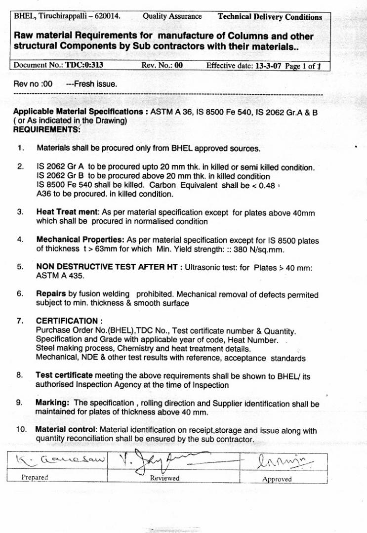


BHARAT HEAVY ELECTRICALS LIMITED
TIRUCHIRAPALLI 620 014
QUALITY ASSURANCE SIP:NP:02 /02 PAGE : 1 Of 11 TRIAL ASSY OF COLUMNS, CEILING GIRDERS, MONORAIL & RUNWAY BEAMS
REV. DATE PREPARED REVIEWED APPROVED
02 31/03/2006 A.Francis GSN Murthy C.R.Raju

SIP:NP: 02 /REVN 02 PAGE: 2 of11
1.0 SCOPE1.1 This procedure specifies the quality requirements for trial assembly
of Ceiling Girders and columns including monorails and runway beamsw.r.t match marking / level marking, and identification beforedispatch.
2.0 REFERENCE DOCUMENTS
Relevant drawings/SQP/QCP
3.0 PRE REQUISITES
3.1 All the sub components to be trial assembled (on leveled surface)shall be fully completed (including NDE checks) and certified and/orcleared except those operations required to be done during or aftertrial assembly.
3.2 Flatness of bottom flange shall be within 1mm when a straight edge iskept at pad seating area of the crossbeam / ceiling girder.
4.0 COLUMNS:
METHODOLOGYAssemblysequence
Top to bottomor bottom totop
Minimum 3 pieces required. Last pieceto be assembled during 2nd stageassembly
No ofstages
Single stageor two stage
Cover plates to be match drilled beforedismantling the trial assembly.
4.1 TRIAL ASSEMBLY OF WELDED TYPE “H” type COLUMNS
a. Assembly position: Flanges vertical, Web horizontal.b. Ensure square ness of matching ends and straightness before trail
assembly.c. Web section depth differences at the matching faces shall be equally
distributed on both flange faces and flange centerlines shall bealigned
d. Ensure proper preheating for tack welding during trial assembly.e. The matching ends shall butt in trial assembly (with 0 gap) with
local gaps not more than 2mm.f. Centerline alignment of flange and web of adjacent sections shall be
within 2 mm as checked by water level and piano wire at joints.g. Out of straightness:
8888 4 mm maximunm for single piece8888 Full assembly: 18mm maximum.8888 Part assembly: 10 mm maximum for 3 pieces.
h. Overall length variation:8888 Individual length: within +/- 3 mm8888 Full assembly: with in +/- 15 mm.8888 Part assembly: with in +/- 5 mm
4.2 TRIAL ASSEMBLY OF BOLTED TYPE ‘H’ Columns
a. Assembly position: Flanges vertical, Web horizontal.
b. End faces of individual pieces: Flat and square to both web andflange axis.
SIP:NP: 02 /REVN 02 PAGE: 3 of11
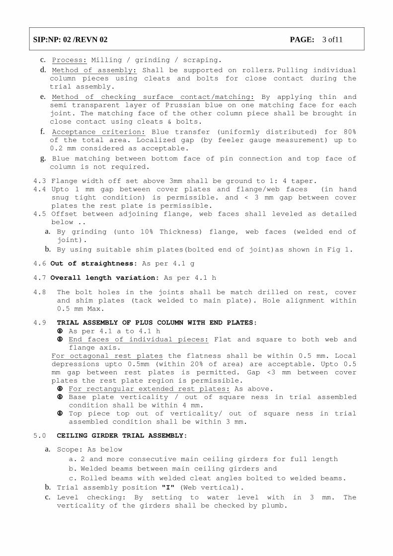
c. Process: Milling / grinding / scraping.
d. Method of assembly: Shall be supported on rollers. Pulling individualcolumn pieces using cleats and bolts for close contact during thetrial assembly.
e. Method of checking surface contact/matching: By applying thin andsemi transparent layer of Prussian blue on one matching face for eachjoint. The matching face of the other column piece shall be brought inclose contact using cleats & bolts.
f. Acceptance criterion: Blue transfer (uniformly distributed) for 80%of the total area. Localized gap (by feeler gauge measurement) up to0.2 mm considered as acceptable.
g. Blue matching between bottom face of pin connection and top face ofcolumn is not required.
4.3 Flange width off set above 3mm shall be ground to 1: 4 taper.4.4 Upto 1 mm gap between cover plates and flange/web faces (in hand
snug tight condition) is permissible. and < 3 mm gap between coverplates the rest plate is permissible.
4.5 Offset between adjoining flange, web faces shall leveled as detailedbelow ..
a. By grinding (unto 10% Thickness) flange, web faces (welded end ofjoint).
b. By using suitable shim plates(bolted end of joint)as shown in Fig 1.
4.6 Out of straightness: As per 4.1 g
4.7 Overall length variation: As per 4.1 h
4.8 The bolt holes in the joints shall be match drilled on rest, coverand shim plates (tack welded to main plate). Hole alignment within0.5 mm Max.
4.9 TRIAL ASSEMBLY OF PLUS COLUMN WITH END PLATES:8888 As per 4.1 a to 4.1 h8888 End faces of individual pieces: Flat and square to both web and
flange axis.For octagonal rest plates the flatness shall be within 0.5 mm. Localdepressions upto 0.5mm (within 20% of area) are acceptable. Upto 0.5mm gap between rest plates is permitted. Gap <3 mm between coverplates the rest plate region is permissible.8888 For rectangular extended rest plates: As above.8888 Base plate verticality / out of square ness in trial assembled
condition shall be within 4 mm.8888 Top piece top out of verticality/ out of square ness in trial
assembled condition shall be within 3 mm.
5.0 CEILING GIRDER TRIAL ASSEMBLY:
a. Scope: As belowa. 2 and more consecutive main ceiling girders for full lengthb. Welded beams between main ceiling girders andc. Rolled beams with welded cleat angles bolted to welded beams.
b. Trial assembly position "I" (Web vertical).
c. Level checking: By setting to water level with in 3 mm. Theverticality of the girders shall be checked by plumb.

SIP:NP: 02 /REVN 02 PAGE: 4 of11
d. The matching ends shall be butted in trial assembly (with 0 gap)with local gaps not more than 3 mm.
e. The girders shall be aligned for top face of the bottom flange.f. After the first compartment trial assembly is completed with girder
1 & 2 girder 2 is taken for further trial assembly with girder 3 andso on.
g. Bottom of steel (BOS)reference shall be transferred to upper sideof tension flange of ceiling girder. Elevation and level of weldedbeams shall be maintained w.r.t to the same.
h. On satisfactory completion of trial assembly, all the boltholes ofcleats shall be match drilled on with Girders/welded beams as shownin drawing.
i. The assembly tolerances are as given below.
Distance between two girders +/- 5mm
Distance between cross beams
For individual +/- 2mm
Overall from center line +/- 5mm
Load bearing stiffener to boiler axis +/- 4mm
Water level variation
Girder 3mm
Cross beam 2mm
Girder Web verticality Lesser of 0.005H 10 mm
Distance between column connection holes +/- 4 mm
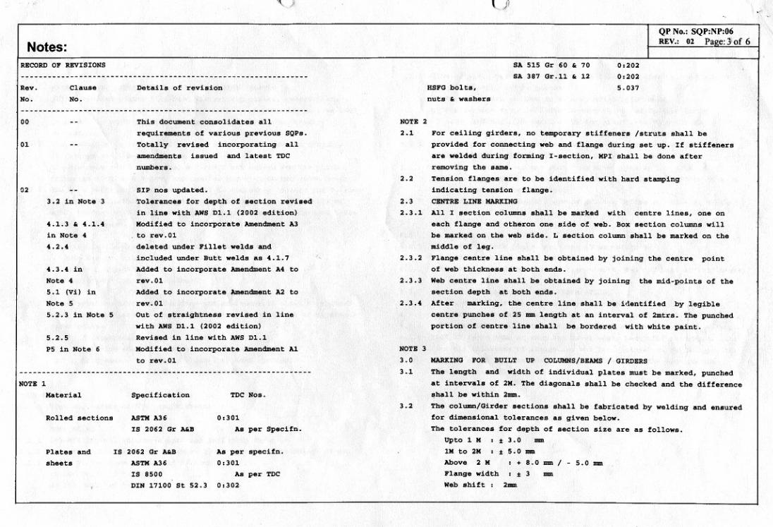
Diagonal difference (See Figure 2)
For each compartment 10mm max.
Total assembly 25mm max.
6.0 MARKING
6.1 MATCH MARKING OF COLUMNS
Each joint shall be identified by a unique letter A, B, C etc.Flange, web and cover plates of each joint will have an alpha numericmarkings like A1-A1, A2-A2, etc. for the flange, web, cover plates.The match marks shall be hard stamped and stenciled shown in Figures3, 3A, 3B & 3C (as applicable).
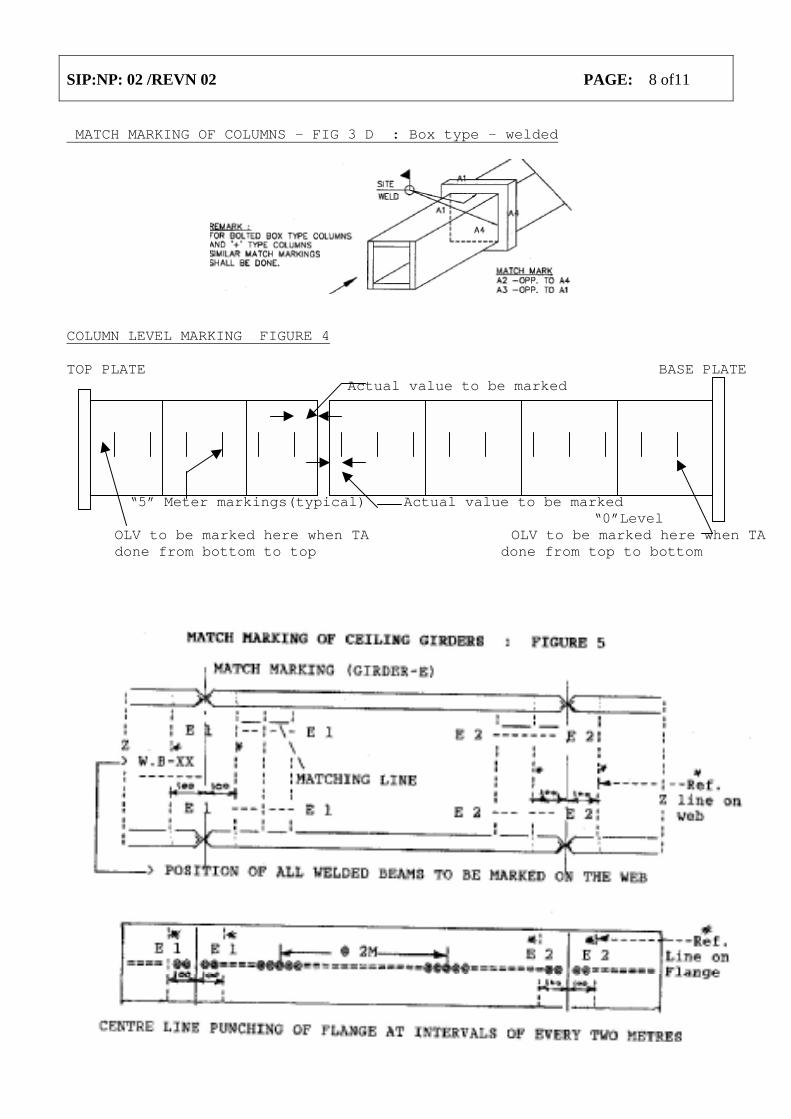
6.2 LEVEL MARKING OF COLUMNS (See figure 4)a. All dimensions shall be measured from the top end only when all
pieces of column are assembled at a time in one assembly. If partassembly from bottom is done, level marking shall be done frombottom.
b. For top to bottom sequence of trial assembly the OLV (Overalllength variation) of the full column shall be marked on the bottommost piece and shall be marked as + * mm or - * mm w.r.t “0” levelof the column.
c. When bottom to top sequence of trial assembly is done in twostages, the OLV (Overall length variation) of the full column shallbe computed progressively based on actual measured values frombottom to top and should be marked on the top most piece and shall

SIP:NP: 02 /REVN 02 PAGE: 5 of11
be marked as + *mm or - *mm as per the actual measurement w.r.t TOS(Top of steel) level of the column. In such cases, the bottom pieceshould be marked at the “0” level as “ See ‘OLV’ on top piece”.This shall also be written with white paint and hard punched andbordered with white paint.
d. When top to bottom sequence of trial assembly is done in twostages, the OLV of the full column shall be computed progressivelybased on actual measured values from top to bottom e. The OLV shallbe marked on the bottom most piece (having base assembly) as + * mmor - * mm w.r.t “0” level of the column.
e. For partial TA from bottom to top the distance between top mostface and immediate lower level marking shall be marked.(see figure4)
f. For first partial started from top , the dimension of bottom end inthe assembly from the nearest level mark above shall be recordedduring the first partial TA. (see figure 4)
g. Even when OLV is found to be nil the same shall be marked as “0”.(Applicable for both cases of trial assembly)
h. Levels in steps of 5 meters shall be punched on the column, taking`0’ level as reference. The levels shall be identified bynumber punching like 0 M, 5 M, 10 M etc., on 3 flange faces in caseof + type and box type, on 2 flanges and web in case of I type andshall be bordered with white paint as shown in Fig. 4. Arrow markshall be stenciled along with level marks with the arrow pointingdownwards.
i. All the cover plates for flange as well as web to be dispatchedalong with the respective columns. Shim plates to be properly setin position and tack welded with respective columns.
j. The cover plate should be turned by 180° then be bolted using twodiagonally opposite bolts. The cover plate should also be tackwelded after bolting as shown in Figure 7. The identificationdetails to be punched/stenciled on flange and cover plates offlange and web are detailed in Figure 8.
6.3 MATCH MARKING OF CEILING GIRDERSa. Prior to dismantling from ceiling girder trial assembly, joints
shall be identified by girder designation (as per drawing) andmatch marked by hard stamping of each girder with unique suffix 1.2.. 3.. etc. Flange & Web at the joint shall be marked with matchmarks as indicated below. (Example: For girder E: E1 - E1 and E2-E2and so on. See Figure 5 for further information).
b. The location of the respective cross beam shall be marked on theweb of the ceiling girder.
c. During trial assembly the cleat angles shall be tack welded/boltedwith the main girder in the respective position and tack weldedto the corresponding crossbeams. Cleat angle locations with girdershall be match marked in the trial assembled condition as indicatedbelow.
d. Compartment E & F: Starting from L.H. enda. “E” girnder E1, E2, E3, E4...E13 AND E14| Compartment EFb. “F” girder F1, F2,F3,F4--F13 AND F14 |c. “F”girder F15,F16,F17,F18..F27 & F28 | Compartment FG
e. The match mark on girder web and cleat angle leg are to be hardstamped and bordered. On the other leg of cleat angle respective WBnumber shall be hard stamped and bordered.

SIP:NP: 02 /REVN 02 PAGE: 6 of11
7.0 TRIAL ASSEMBLY OF MONORAILS AND RUNWAY BEAMS
a. Measure the I section size and web offset of the individual beamsand select the matching ends before proceeding with any furtheroperation.
b. All the beams shall be trial assembled on level surface (pertainingto single row). Trial assembly can be done in two stages when it isnot possible to carry out in single row. All pieces of runway beamsshall be trial assembled as per layout drawing.
c. Verify the matching of bottom flange inner surface at the joint ofconsecutive beam. The level difference between the flange face atbottom and top shall be adjusted by grinding to accommodate spliceplate / beams.
d. Out of straightness on total length 10mm maximum.e. Individual beam length between supports limited to +0 mm / -2 mm.
8.0 IDENTIFICATION & CERTIFICATION
8.1 The results of trial assembly shall be documented and signed off byinspection agency /QC before dismantling.
FIGURE 1: COVER PLATE/SHIM PLATE MARKING before dispatch.

SIP:NP: 02 /REVN 02 PAGE: 7 of11
Figure 2
MATCH MARKING OF COLUMNS – FIG 3 A: I TYPE - BOLTED
MATCH MARKING OF COLUMNS – FIG 3B: PLUS TYPE - BOLTED
MATCH MARKING OF COLUMNS – FIG 3C : I type – welded
SIP:NP: 02 /REVN 02 PAGE: 8 of11
MATCH MARKING OF COLUMNS – FIG 3 D : Box type – welded
COLUMN LEVEL MARKING FIGURE 4 TOP PLATE BASE PLATE
Actual value to be marked
“5” Meter markings(typical) Actual value to be marked“0”Level
OLV to be marked here when TA OLV to be marked here when TAdone from bottom to top done from top to bottom

SIP:NP: 02 /REVN 02 PAGE: 9 of11

SIP:NP: 02 /REVN 02 PAGE: 10 of11

SIP:NP: 02 /REVN 02 PAGE: 11 of11

BHARAT HEAVY ELECTRICALS LIMITED
TIRUCHIRAPALLI 620 014
QUALITY ASSURANCE SIP:NP:09 /01 PAGE : 1 Of 6
TRIAL ASSEMBLY OF DIAGONAL BRACING (BOLTED CONNECTION)
REV. DATE PREPARED REVIEWED APPROVED
01 05/04/2004 A.Francis GSN Murthy C.R.Raju

SIP:NP:09/01 PAGE 2 OF 6 ------------------------------------------------------------- REVISION STATUS -------------------------------------------------------------- REVISION NO: CLAUSE NO DETAIL OF REVISION 01 1.0, Modified for better clarity. 6.5, 6.6, 6.7 Added based on site feed back. 7.1.1 Modified for better clarity.

SIP:NP:09/01 PAGE 3 OF 6
1.0 SCOPE
This procedure details out the requirements for trial assembly of diagonal bracings (including gusset plates) of bolted type with columns, match marking and identification prior to dispatch.
2.0 REFERENCE DOCUMENTS
Relevant drawings/SQP:NP:06 & SQP:NP:07/OPS and SIP:NP:02 3.0 PRE REQUISITES 3.1 The bracings to be trial assembled shall be fully completed except for
those operations which are necessarily to be done during or after trial assembly.
3.2 Necessary NDE checks shall be completed before taking the
components for trial assembly. 3.3 Necessary certification shall be completed before taking the
components for trial assembly and clearance of concerned inspection agency shall be obtained for trial assembly, wherever envisaged.
3.4 Trial assembly shall be laid out on a level surface. 4.0 LAYOUT MARKING 4.1 Full scale layout of the columns and the diagonal bracings and gusset
plates for each tier shall be made as per drawing dimensions. Size and squareness of the layout shall be ensured by verifying the width, length and diagonals.
4.2 Care shall be taken to suitably overlap the 25mm site allowance
provided in the gusset plates on the column flanges while marking the layout.
4.3 Sufficient size of plates/sheets shall be used on all the four corners
of the layout so that full details of the gusset plates, bracing size, drill pitches and work points are marked as per drawing dimensions.
4.4 Gusset plate to be cut / trimmed to the required shape only after
verifying the gusset plate size in the full scale layout. 4.5 Bracing along with the gusset plates shall be laid out on the layout.
Bolt hole locations shall be marked on the gusset plates. 4.6 Bolt holes on the gusset plate and bracing shall be drilled together in
matched condition.
SIP:NP:09/01 PAGE 4 OF 6
5.0 TRIAL ASSEMBLY OF BRACING AND GUSSET PLATES
5.1 After match drilling, diagonal bracing along with gusset plate shall be laid out on the layout for inspection.
5.2 Layout dimensions shall be marked on the top side of the assembly also.
5.3 After ensuring the width, length and diagonals, the dimensions of work point, bolt hole locations and pitches and orientation of bolt holes with respect to center lines and gusset plates shall be verified.
5.4 For the bottom most bracing, where the bracing joins with the column base, the verticality and co-axiality of the holes shall be verified by plumb after water leveling the bracing. The co-axiality shall be maintained within 1mm.
6.0 TOLERANCES
6.1 Diagonal difference = 5mm max. 6.2 Work point dimension = + / - 2mm 6.3 Bolt hole pitches Individual = + / - 1mm Cumulative = + / - 2mm
6.4 Hole size and verticality shall be checked with a 'Go' and 'No Go' gauges. (Refer sketch-1) 6.5 Inside Distance between Gusset plates : - 0 , + 3 mm 6.6 Distance between bracing seating faces: + 0 , - 3 mm 6.7 Gauge/template for checking should confirm to 6.5 and 6.6
requirements.
7.0 MATCH MARKING
7.1 Bracing and gusset plates and shim plates shall be match marked before dismantling.
7.1.1 All bracings and gussets will be match marked with an alphabet followed by numerals such as .
Lower bracing as 'A' with running Sl.No. like A1,A2 etc., Middle bracing as'B' with running Sl.No. like B1,B2 etc., Upper bracing as 'C' with running Sl.No. like C1,C2 etc., as per Sketch-2
Where more than one identical gussets are envisaged under same DU, additional alphabet like L (for LHS), R (for RHS), F ( for Front ) , R (for Rear) can be added (as necessary) to the existing identification for extra clarity.

SIP:NP:09/01 PAGE 5 OF 6
Refer Clause 6.4
7.1.2 The match marks shall be hard stamped on gusset plates and bracings

SIP:NP:09/01 PAGE 6 OF 6
before dismantling the trial assembly.
7.1.3 The match marks shall also be stenciled after painting.
TYPICAL VIEW .