Embed Size (px)
Citation preview
Aligned Single-Wall Carbon Nanotube PolymerComposites Using an Electric Field
CHEOL PARK,1 JOHN WILKINSON,2 SUMANTH BANDA,3 ZOUBEIDA OUNAIES,3 KRISTOPHER E. WISE,1
GODFREY SAUTI,4 PETER T. LILLEHEI,5 JOYCELYN S. HARRISON5
1National Institute of Aerospace, NASA Langley Research Center, Hampton, Virginia 23681
2Department of Electrical Engineering, Virginia Tech, Blacksburg, Virginia
3Department of Mechanical Engineering, Virginia Commonwealth University, Richmond, Virginia
4School of Physics, University of the Witwatersrand, Milner Park, Johannesburg, South Africa
5Advanced Materials and Processing Branch, NASA Langley Research Center, Hampton, Virginia 23681
Received 4 November 2005; revised 2 March 2006; accepted 24 March 2006DOI: 10.1002/polb.20823Published online in Wiley InterScience (www.interscience.wiley.com).
ABSTRACT: While high shear alignment has been shown to improve the mechanicalproperties of single-wall carbon nanotube (SWNT)-polymer composites, this method doesnot allow for control over the electrical and dielectric properties of the composite and of-ten results in degradation of these properties. Here, we report a novel method to activelyalign SWNTs in a polymer matrix, which permits control over the degree of alignment ofthe SWNTs without the side effects of shear alignment. In this process, SWNTs werealigned via AC field-induced dipolar interactions among the nanotubes in a liquid matrixfollowed by immobilization by photopolymerization under continued application of theelectric field. Alignment of SWNTs was controlled as a function of magnitude, frequency,and application time of the applied electric field. The degree of SWNT alignment wasassessed using optical microscopy and polarized Raman spectroscopy, and the morphol-ogy of the aligned nanocomposites was investigated by high-resolution scanning electronmicroscopy. The structure of the field induced aligned SWNTs was intrinsically differentfrom that of shear aligned SWNTs. In the present work, SWNTs are not only alignedalong the field, but also migrate laterally to form thick, aligned SWNT percolative col-umns between the electrodes. The actively aligned SWNTs amplify the electrical anddielectric properties of the composite. All of these properties of the aligned nanocompositesexhibited anisotropic characteristics, which were controllable by tuning the applied fieldparameters.VVC 2006Wiley Periodicals, Inc.* J Polym Sci Part B: Polym Phys 44: 1751–1762, 2006
Keywords: alignment; electric field; nanocomposite; photopolymerization; single-wall carbon nanotube
INTRODUCTION
Single-wall carbon nanotubes (SWNTs) have beenconsidered for a number of applications because of
their unique combinations of superb electrical, me-chanical, and thermal properties.1 Successful struc-tural reinforcement of polymer matrices by SWNTshas been reported where significant improvementof mechanical properties was achieved at very lowSWNT loadings.2–7 Recently, sensing and actuatingcapabilities of SWNTs and SWNT-polymer compo-sites have been studied in response to temperature,
Correspondence to: C. Park (E-mail: [email protected])
Journal of Polymer Science: Part B: Polymer Physics, Vol. 44, 1751–1762 (2006)VVC 2006 Wiley Periodicals, Inc. *This article is a US Government work and, as
such, is in the public domain in the United States of America.
1751
chemical vapors, strain, stress, electrochemical,and electrical stimuli.8–13 Shear forces have beenfrequently used for aligning inclusions along theflow direction to reinforce mechanical properties.Although shear alignment of SWNTs can improvemechanical properties in the shear direction, elec-tric and dielectric properties tend to decrease alongthe shear direction as well as in the perpendiculardirection with increasing SWNT orientation.Kumar et al.6 showed that a well-aligned 10 wt %SWNT-PBO (poly(p-phenylene benzbisoxazole))composite fiber exhibited an electrically insulat-ing behavior while achieving significant mechani-cal reinforcement along the fiber direction. Thisloading level is at least two orders of magnitudehigher than the percolation concentration of anunaligned SWNT polymer composite. This lowconductivity can be understood by consideringthe low statistical probability of contacts amongthe aligned fibers along the orientation direction,which is consistent with the predictions ofexcluded volume theory.14,15 These results indi-cate that shear alignment of SWNTs may not be apractical method of augmenting nanocompositeproperties beyond mechanical reinforcement. Theonly way of circumventing this difficulty withshear processing would be to further increase theloading of SWNTs, which would limit its versatil-ity for developing multifunctional materials forspecific demands.
In the present report, a novel method is intro-duced which allows for control over the electricaland dielectric properties of a SWNT-polymer com-posite by aligning SWNTs under an AC electricfield. Alignment of SWNTs by electric or magneticfields has previously been reported,16–20 thoughusually in dilute solutions during solvent evapora-tion or filtration. More recently, very limited align-ment of SWNTs in a polymer matrix was achievedusing a magnetic field21 and a thermally curedaligned SWNT epoxy composite prepared under anelectric field was reported.22 In the present work,control over the degree of alignment of SWNTs ina photopolymerizable monomer solution wasachieved by adjusting the applied field strength,frequency, and application time. The conductivityand dielectric properties can be tailored over severalorders of magnitude by adjusting these parameters.
EXPERIMENTAL
The photopolymerizable monomer used in this studyis a blend of urethane dimethacrylate (UDMA)
and 1,6-hexanediol dimethacrylate (HDDMA) atthe ratio of 9 to 1 (UDMA/HDDMA(9/1) ¼ UH).The viscosities were 12.5 Pa�s and 7.0 � 10�3
Pa�s for UDMA and HDDMA, respectively.23
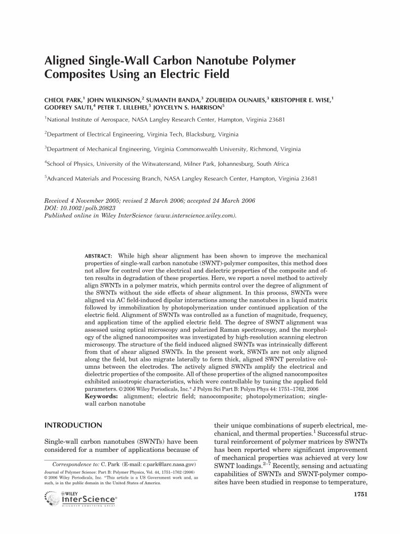
Both UDMA and HDDMA monomers can bepolymerized by blue light with camphorquinoneas a photoinitiator and N,N-dimethylaminoethylmethacrylate as an accelerator. The monomerscould be solidified to a depth of 3 mm within about3 s under illumination by intense blue light. Sin-gle-wall carbon nanotubes (SWNTs) synthesizedby a high-pressure CO (HiPco) method (CNI, TX)were used as multifunctional inclusions. A knownquantity of SWNTs (fluffy powders) were added tothe less viscous HDDMA monomer in a beakerand mixed vigorously by homogenizing for 10 min(750 rpm with a 6 mm diameter rotor homoge-nizer) and sonicated for an hour at 47 kHz. Then,the SWNT/HDDMA solution was mixed withthe UDMA monomer with a mechanical stirrerto produce a 0.03% SWNT/UDMA/HDDMA(9/1)(¼ SWNT/UH) solution. The photoinitiator andaccelerator were added into the SWNT/UH solu-tion in a dark room. This solution was transferredinto a microcuvet cell with electrodes on two nar-row sides. A schematic of the alignment and pho-topolymerization apparatus is shown in Figure 1.Either a pure UH monomer solution or 0.03 wt %SWNT/UH composite solution was added in the1 mm deep cell between the electrodes spaced at2.3 mm. The 0.03 wt % concentration was selectedas it is expected to be below the percolationthreshold, based on previous percolation studies
Figure 1. (a) Experimental setup of photopolymeri-zation of SWNT/UH composite under an electric field;(b) top-view of the alignment cell (aligned SWNTsshown as discontinuous lines). [Color figure can beviewed in the online issue, which is available atwww.interscience.wiley.com.]
1752 PARK ET AL.
Journal of Polymer Science: Part B: Polymer PhysicsDOI 10.1002/polb
of various SWNT-polymer composites.24,25 Thisconcentration also allows one to efficiently curethe control sample across its 1 mm thickness. AnAC power supply (Trek model 50/750) and a func-tion generator (Hewlett-Packard 33120A) wereused to control the applied electric field condi-tions. The influence of the AC field parameterswas studied by varying the field strength (10–250Vp–p as a step function), time (1–60 min), and fre-quency (10�3 to 105 Hz). The polymerization reac-tion was initiated using blue light with a hand-held light gun (Optilux 501) for 1 min while thefield was being applied. The solidified sampleswere cured by blue light for another 10 min andthen annealed at 110 8C in an oven overnight tofurther complete polymerization. The cured sam-ples were first investigated with an optical micro-scope. For electrical and dielectric measurements,the samples were sectioned into rectangularblocks with a low-speed diamond saw, andthen polished with a 1 lm diamond paste to ex-pose fresh surfaces, which were electroded with asilver paste. For high-resolution scanning elec-tron microscopy (HRSEM) studies, the sampleswere microtomed with a diamond knife. The ACconductivity and dielectric constants of theSWNT/UH composites were measured with aNovocontrol Broadband Dielectric Converter anda Solatron SI1260 Impedance/Gain-Phase Ana-lyzer. Polarized Raman scattering spectra werecollected using a Thermo Nicolet AlmegaTM dis-persive visible Raman spectrometer. A 785 nmincident laser light excitation was used with a po-larizer, and the laser beam was focused on thesample using an optical microscope. A low-excita-tion laser power (10 mW) was used to minimizesample heating. The actual dose of the laser dropslower than 10 lWafter it passes through the spec-trometer optics.
RESULTS AND DISCUSSION
Within the present experimental setup, thereare three controllable parameters for influencingthe degree of SWNT alignment: electric fieldstrength, application time, and the frequency ofthe applied AC field. Optimal values for theseparameters have been obtained by varying eachin turn, while holding the other two constant.This actually requires an iterative process inwhich the values held fixed are determined by anumber of preliminary experiments. In what fol-
lows, only the final set of experiments is de-scribed.
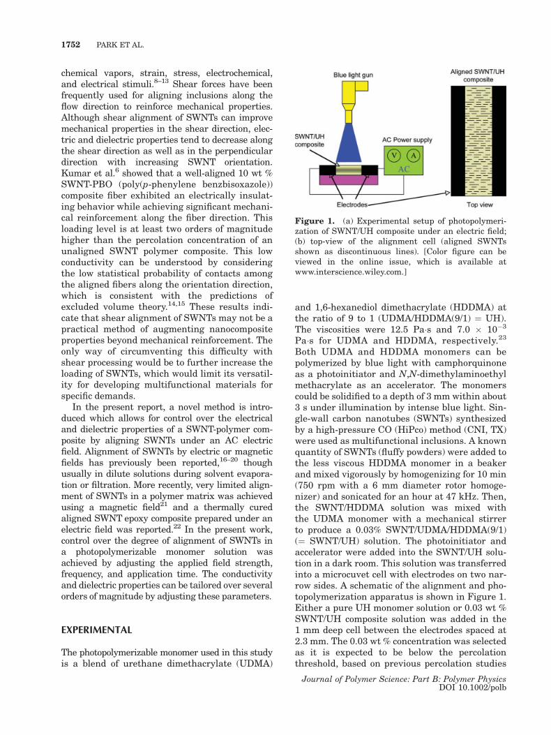
For the electric field strength optimization, thefield application time was held fixed at 10 minwhile two AC frequencies were investigated,100 Hz and 10 kHz. Various selected electricfields were applied as a step function at this con-dition. It was found that the degree of alignmentwas strongly dependent on the applied electricfield and the same trends were observed with thetwo AC frequencies studied, 100 Hz and 10 kHz.No alignment was observed below 65 Vp–p, andalignment became noticeable at 75 Vp–p (37.5 V/2.3
Figure 2. Optical micrographs of (a) SWNT/UH com-posite cured without electric field, (b) SWNT-UH com-posite cured with electric field (200 Vp–p, 10 Hz, 10 min).Note that the alignment of SWNTs along the appliedelectric field (EFl). [Color figure can be viewed in theonline issue, which is available at www.interscience.wiley.com.]
ALIGNMENT OF SWNTs USING AN ELECTRIC FIELD 1753
Journal of Polymer Science: Part B: Polymer PhysicsDOI 10.1002/polb
mm ¼ 16.3 kV/m for a step function). The degreeof alignment continued to increase up to a plateauvalue at 200 Vp–p (43.5 kV/m). Increasing the volt-age beyond this point tended to induce moreskewed alignment near the electrodes possibly dueto excessive thermal energy. Beyond 300 Vp–p, thetemperature of the composite increased signifi-cantly due to Joule heating (higher than 100 8C),which tended to locally disrupt or bend the alignednanotubes. Next, the effect of field application timewas studied at a fixed voltage of 200 Vp–p and fre-quency of 10 kHz. These experiments showed thatalignment began almost immediately and grewwith increasing field application time until satura-
tion was observed at around 10 min. Finally, theeffect of field frequency was studied at 200 Vp–p foran application time of 10 min. In this case, thedegree of alignment grew with increasing fre-quency, saturating at 10 Hz. Interestingly theSWNTs were observed to align to some degree atfrequencies as low as 0.001 Hz, which is effectivelya DC condition, although this requires a much lon-ger field application time.
Optical microscopy was used for initial, quali-tative evaluation of the degree of alignment. Fig-ure 2(a) shows an optical micrograph of a SWNT/UH composite cured without an electric field,which reveals a relatively uniform dispersion
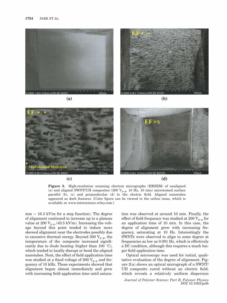
Figure 3. High-resolution scanning electron micrographs (HRSEM) of unaligned(a) and aligned SWNT/UH composites (200 Vp–p, 10 Hz, 10 min) microtomed surfaceparallel (b), (c) and perpendicular (d) to the electric field. Aligned nanotubesappeared as dark features. [Color figure can be viewed in the online issue, which isavailable at www.interscience.wiley.com.]
1754 PARK ET AL.
Journal of Polymer Science: Part B: Polymer PhysicsDOI 10.1002/polb
overall with a few micrometer scale agglomeratesand no preferential alignment or elongated fea-tures. Figure 2(b) shows a micrograph of thealigned composite prepared at 200 Vp–p and10 Hz for 10 min, where aligned SWNT bundlesare seen along the field direction and the micro-meter scale agglomerates are also aligned withtheir elongated axes along the field direction.
More detailed microstructures of the alignedSWNTs were investigated with high-resolutionscanning electron microscopy (HRSEM). Thecomposites were microtomed either parallel orperpendicular to the field direction and examinedwithout a conductive coating at a low voltage(below 1 kV). Figure 3(a) shows the microtomedsurface of the unaligned sample, in which thenanotubes could not be imaged due to the noncon-ducting behavior of the sample. Figure 3(b) showsthe SWNT aligned along the field, with some ofthe aligned clusters extending several hundred
micrometers in length. The aligned clusters alongthe field are seen to be composed of a series ofsmall SWNT clusters ranging from tens of nano-meters to a few micrometers. Some of the alignedSWNT clusters lie parallel to one another and areconnected with jagged or fray aligned clusters(coarsening). This aligned microstructure is remi-niscent of the dielectrophoretic alignment andsubsequent lateral coarsening of inclusions oftenobserved in electrorheological or magnetorheolog-ical fluids.23,26 This coarsening, which arises fromthe lateral migration among the aligned nano-tubes, creates conductive percolation paths evenat loadings as low as 0.03%. This permits forma-tion of a stable electric field permitting visualiza-tion of the SWNTs that are part of the percolationpaths. Although alignment of SWNT bundles andclusters was evident at higher magnification asshown in Figure 3(c), alignment of individualSWNTs in the clusters was not discernible due to
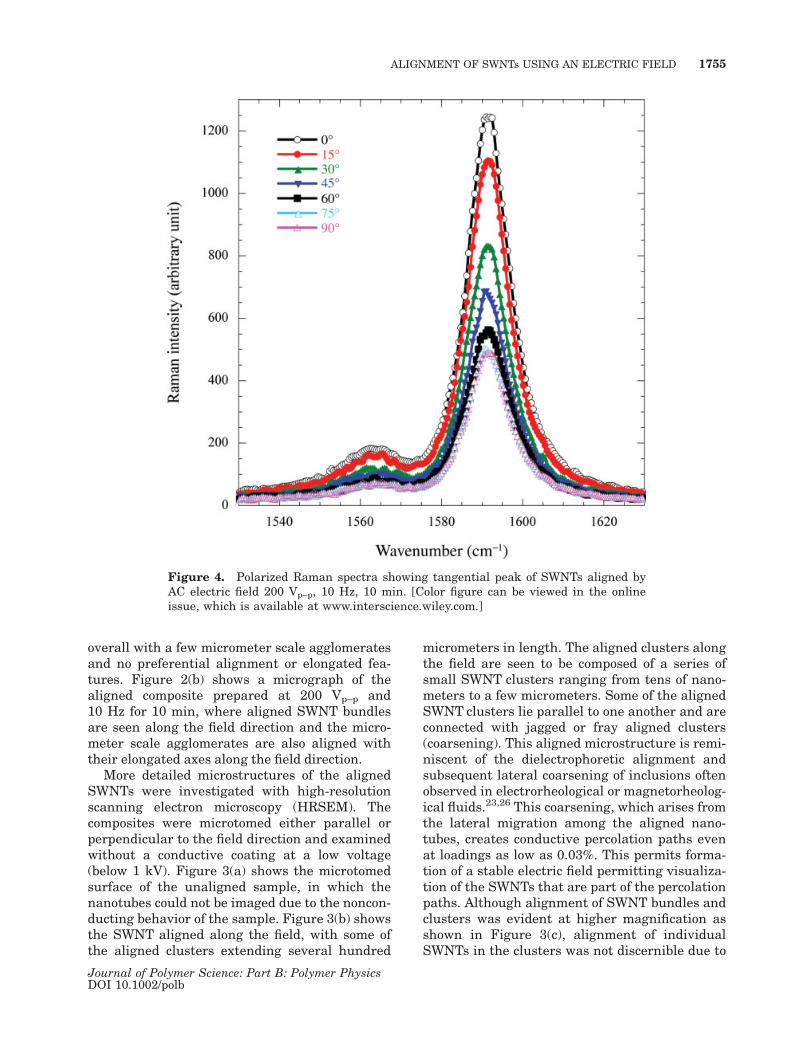
Figure 4. Polarized Raman spectra showing tangential peak of SWNTs aligned byAC electric field 200 Vp–p, 10 Hz, 10 min. [Color figure can be viewed in the onlineissue, which is available at www.interscience.wiley.com.]
ALIGNMENT OF SWNTs USING AN ELECTRIC FIELD 1755
Journal of Polymer Science: Part B: Polymer PhysicsDOI 10.1002/polb
the severe bleaching near the clusters. [Note thatthe small upward spikes shown in the alignedSWNTs in Fig. 3(c) result from microtoming.] It isalso notable that there was little indication of anyelectrophoretic effect, which would be indicatedby migration of SWNTs to the electrodes. Figure3(d) shows a surface microtomed perpendicular tothe electric field direction from the same alignedSWNT/UH composite. In this sample, evenly dis-tributed, round SWNT clusters were observed,which are believed to be the cross sections of thealigned SWNT clusters shown in Figure 3(b). Thisindicates the distinct anisotropic nature of thealigned SWNT/UH composites and is similar tothe anisotropic morphology observed in othercomposite systems containing spherical or equi-axed inclusions aligned under electric fields.23
The degree of alignment of SWNTs in thealigned composite was also assessed by polarizedRaman spectroscopy. This characterization relies
on the fact that the Raman intensity of the tan-gential mode of SWNTs is sensitive to the polar-izer angle. The tangential mode intensity reachesa maximum when the polarized light is parallelto the nanotube axis27 and decreases gradually asthe angle of the polarizer increases from 08 (par-allel to the nanotube axis) to 908 (perpendicularto the nanotube axis). The intensity begins toincrease again as the angle of the polarizerincreases from 908 to 1808. The tangential peaks(1591 cm�1) of the polarized Raman spectra forthe composite aligned at 10 Hz are shown for a se-ries of angles in Figure 4. As expected, the maxi-mum intensity was observed when the polarizedlight was parallel to the applied electric fielddirection (08) and the smallest intensity appearedwhen the polarized light was perpendicular to thefield direction (908). Similar results were obtainedfor the composites aligned at frequencies rangingfrom 10 Hz to 100 kHz. The polarized Raman
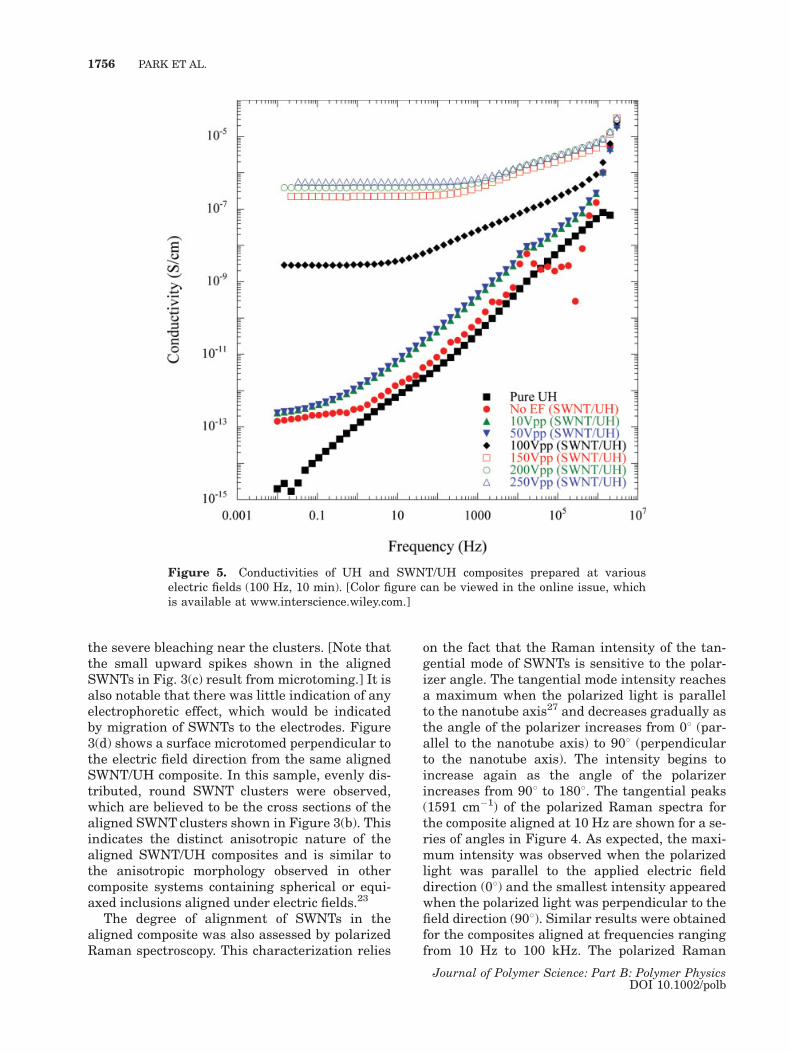
Figure 5. Conductivities of UH and SWNT/UH composites prepared at variouselectric fields (100 Hz, 10 min). [Color figure can be viewed in the online issue, whichis available at www.interscience.wiley.com.]
1756 PARK ET AL.
Journal of Polymer Science: Part B: Polymer PhysicsDOI 10.1002/polb
results effectively demonstrate the preferentialalignment of the individual SWNTs in the alignedSWNT bundles and clusters that resulted fromthe AC electric field.
Electrical Conductivity of SWNT/UH Composites
The conductivities of the pristine matrix resinUH and the unaligned and aligned compositescontaining 0.03 wt % SWNT are shown in Fig-ure 5 as a function of the measurement fre-quency. Figure 5 shows the conductivities mea-sured along the field direction for samples pre-pared at a series of applied voltages. At 1 Hz,the conductivities of the pristine resin andunaligned composite were 1.4 � 10�13 and 3.3� 10�13 S/cm, respectively, revealing less thanan order of magnitude increase in conductivityupon addition of 0.03 wt % SWNT. The conduc-tivities of both of these samples increased line-
arly with the frequency on a logarithmic scaleacross most of the frequency range, indicatinginsulative behavior and therefore a lack of per-colation at the 0.03 wt % SWNT loading. Forthe aligned composites, the conductivity of thesamples in the aligned direction increases mar-ginally up to 50 Vp–p, followed by a jump from1.4 � 10�12 to 3.0 � 10�9 S/cm at 100 Vp–p. Fur-ther increases were observed for higher align-ment fields up to saturation at around 150 Vp–p,where the conductivity is on the order of 10�7 S/cm. Metallic behavior was observed for the sam-ples aligned above 100 Vp–p, as indicated by therelatively constant conductivity observed at lowfrequencies (below 102 Hz), which increasesslightly at higher frequencies (above 102 Hz).These results indicate that the conductivity ofthe composites can be controlled over six ordersof magnitude by controlling the strength of thealigning electric field.
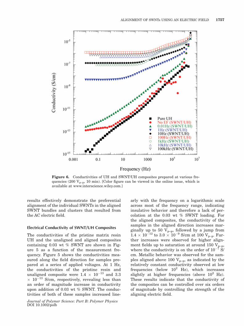
Figure 6. Conductivities of UH and SWNT/UH composites prepared at various fre-quencies (200 Vp–p, 10 min). [Color figure can be viewed in the online issue, which isavailable at www.interscience.wiley.com.]
ALIGNMENT OF SWNTs USING AN ELECTRIC FIELD 1757
Journal of Polymer Science: Part B: Polymer PhysicsDOI 10.1002/polb
The influence of the frequency of the appliedelectric field on the conductivity is shown in Figure6. All of the aligned samples in the Figure 6 wereformed under a field of 200 Vp–p for 10 min, atthe various frequencies. The conductivity in thealignment direction of the composite prepared at0.01 Hz, was slightly higher than that of theunaligned composite, but still showed insulatingbehavior. A significant increase was observed forthe sample prepared at 1 Hz, with the conductivityincreasing from 3.3 � 10�13 (no field) to 4.6 � 10�9
S/cm, which indicates a transition from insulatingto metallic. At 10 Hz, the conductivity increases to1.4 � 10�7 S/cm and reaches a plateau value of10�6 S/cm at 100 Hz, saturating at higher frequen-cies. These results may indicate that, at very lowfrequencies, the misaligning forces, such asBrownian motion and electrophoretic force, arestronger than the aligning dielectrophoretic force,preventing or disrupting nanotube alignment.Above 1 Hz, where electrophoresis becomes insig-nificant, the aligning dielectrophoretic force be-comes dominant, saturating above 100 Hz. Simi-larly to the previous case of field strength, theseresults show that the conductivity of SWNT/UHcomposites can be readily controlled by the AC fre-quency. Conductivities ranging from insulating(10�13 S/cm) to conductive (10�6 S/cm) can beachieved in the alignment direction with a 0.03 wt% SWNT loading, which is lower than the percola-tion concentration for an isotropic dispersion.5,24,25
Although slight alignment was observed at lowerfrequencies (0.01 and 0.1 Hz), it was not reflectedin the conductivity of the composite, suggestingthat the aligned clusters of the SWNT bundles per-colate above 0.1 Hz under these conditions.
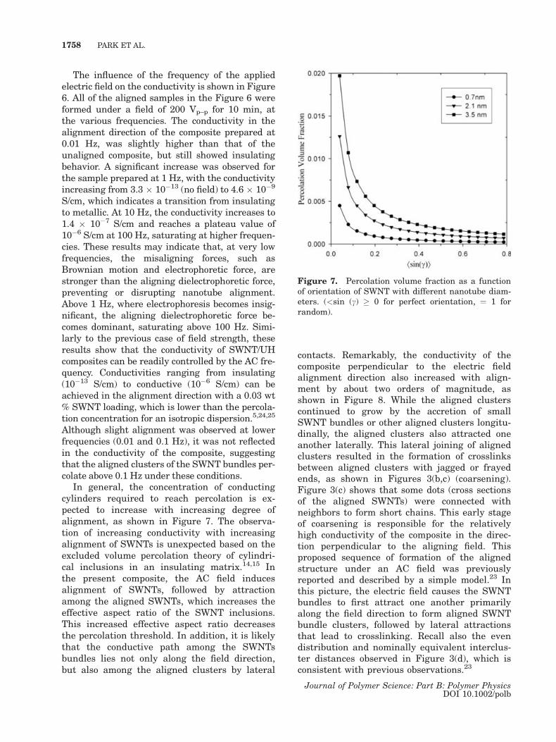
In general, the concentration of conductingcylinders required to reach percolation is ex-pected to increase with increasing degree ofalignment, as shown in Figure 7. The observa-tion of increasing conductivity with increasingalignment of SWNTs is unexpected based on theexcluded volume percolation theory of cylindri-cal inclusions in an insulating matrix.14,15 Inthe present composite, the AC field inducesalignment of SWNTs, followed by attractionamong the aligned SWNTs, which increases theeffective aspect ratio of the SWNT inclusions.This increased effective aspect ratio decreasesthe percolation threshold. In addition, it is likelythat the conductive path among the SWNTsbundles lies not only along the field direction,but also among the aligned clusters by lateral
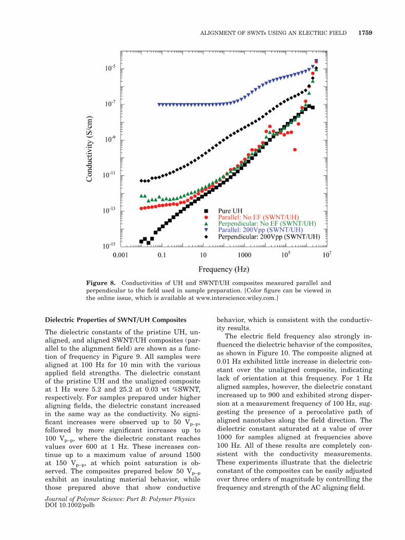
contacts. Remarkably, the conductivity of thecomposite perpendicular to the electric fieldalignment direction also increased with align-ment by about two orders of magnitude, asshown in Figure 8. While the aligned clusterscontinued to grow by the accretion of smallSWNT bundles or other aligned clusters longitu-dinally, the aligned clusters also attracted oneanother laterally. This lateral joining of alignedclusters resulted in the formation of crosslinksbetween aligned clusters with jagged or frayedends, as shown in Figures 3(b,c) (coarsening).Figure 3(c) shows that some dots (cross sectionsof the aligned SWNTs) were connected withneighbors to form short chains. This early stageof coarsening is responsible for the relativelyhigh conductivity of the composite in the direc-tion perpendicular to the aligning field. Thisproposed sequence of formation of the alignedstructure under an AC field was previouslyreported and described by a simple model.23 Inthis picture, the electric field causes the SWNTbundles to first attract one another primarilyalong the field direction to form aligned SWNTbundle clusters, followed by lateral attractionsthat lead to crosslinking. Recall also the evendistribution and nominally equivalent interclus-ter distances observed in Figure 3(d), which isconsistent with previous observations.23
Figure 7. Percolation volume fraction as a functionof orientation of SWNT with different nanotube diam-eters. (<sin (c) � 0 for perfect orientation, ¼ 1 forrandom).
1758 PARK ET AL.
Journal of Polymer Science: Part B: Polymer PhysicsDOI 10.1002/polb
Dielectric Properties of SWNT/UH Composites
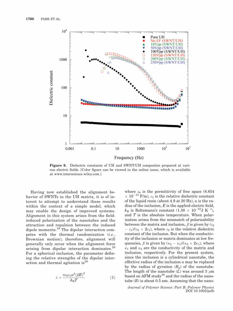
The dielectric constants of the pristine UH, un-aligned, and aligned SWNT/UH composites (par-allel to the alignment field) are shown as a func-tion of frequency in Figure 9. All samples werealigned at 100 Hz for 10 min with the variousapplied field strengths. The dielectric constantof the pristine UH and the unaligned compositeat 1 Hz were 5.2 and 25.2 at 0.03 wt %SWNT,respectively. For samples prepared under higheraligning fields, the dielectric constant increasedin the same way as the conductivity. No signi-ficant increases were observed up to 50 Vp–p,followed by more significant increases up to100 Vp–p, where the dielectric constant reachesvalues over 600 at 1 Hz. These increases con-tinue up to a maximum value of around 1500at 150 Vp–p, at which point saturation is ob-served. The composites prepared below 50 Vp–p
exhibit an insulating material behavior, whilethose prepared above that show conductive
behavior, which is consistent with the conductiv-ity results.
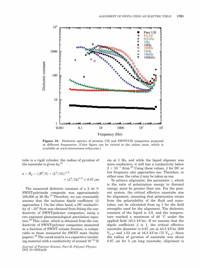
The electric field frequency also strongly in-fluenced the dielectric behavior of the composites,as shown in Figure 10. The composite aligned at0.01 Hz exhibited little increase in dielectric con-stant over the unaligned composite, indicatinglack of orientation at this frequency. For 1 Hzaligned samples, however, the dielectric constantincreased up to 900 and exhibited strong disper-sion at a measurement frequency of 100 Hz, sug-gesting the presence of a perocolative path ofaligned nanotubes along the field direction. Thedielectric constant saturated at a value of over1000 for samples aligned at frequencies above100 Hz. All of these results are completely con-sistent with the conductivity measurements.These experiments illustrate that the dielectricconstant of the composites can be easily adjustedover three orders of magnitude by controlling thefrequency and strength of the AC aligning field.
Figure 8. Conductivities of UH and SWNT/UH composites measured parallel andperpendicular to the field used in sample preparation. [Color figure can be viewed inthe online issue, which is available at www.interscience.wiley.com.]
ALIGNMENT OF SWNTs USING AN ELECTRIC FIELD 1759
Journal of Polymer Science: Part B: Polymer PhysicsDOI 10.1002/polb
Having now established the alignment be-havior of SWNTs in the UH matrix, it is of in-terest to attempt to understand these resultswithin the context of a simple model, whichmay enable the design of improved systems.Alignment in this system arises from the field-induced polarization of the nanotubes and theattraction and repulsion between the induceddipole moments.28 The dipolar interaction com-petes with the thermal randomization (i.e.,Brownian motion); therefore, alignment willgenerally only occur when the alignment forcearising from dipolar interaction dominates.28
For a spherical inclusion, the parameter defin-ing the relative strengths of the dipolar inter-action and thermal agitation is29
k ¼ pe0e1a3ðbEÞ2kBT
ð1Þ
where e0 is the permittivity of free space (8.854� 10�12 F/m), e1 is the relative dielectric constantof the liquid resin (about 4.9 at 20 Hz), a is the ra-dius of the inclusion, E is the applied electric field,kB is Boltzmann’s constant (1.38 � 10�23J K�1),and T is the absolute temperature. When polar-ization arises from the mismatch of polarizabilitybetween the matrix and inclusion, b is given by (e2� e1)/(e2 þ 2e1), where e2 is the relative dielectricconstant of the inclusion. But when the conductiv-ity of the inclusion or matrix dominates at low fre-quencies, b is given by (j2 � j1)/(j2 þ 2j1), wherej1 and j2 are the conductivity of the matrix andinclusion, respectively. For the present system,since the inclusion is a cylindrical nanotube, theeffective radius of the inclusion a may be replacedby the radius of gyration (Rg) of the nanotube.The length of the nanotube (L) was around 3 lmbased on AFM study30 and the radius of the nano-tube (R) is about 0.5 nm. Assuming that the nano-
Figure 9. Dielectric constants of UH and SWNT/UH composites prepared at vari-ous electric fields. [Color figure can be viewed in the online issue, which is availableat www.interscience.wiley.com.]
1760 PARK ET AL.
Journal of Polymer Science: Part B: Polymer PhysicsDOI 10.1002/polb
tube is a rigid cylinder, the radius of gyration ofthe nanotube is given by,31
a ¼ Rg ¼ ððR2=2Þ þ ðL2=12ÞÞ1=2
� ðL2=12Þ1=2 � 0:87 lm
The measured dielectric constant of a 2 wt %SWNT-polyimide composite was approximately100,000 at 20 Hz.13 Therefore, we can reasonablyassume that the inclusion dipole coefficient (b)approaches 1. On the other hand, a DC conductiv-ity of �102 S/cm was obtained from fitting the con-ductivity of SWNT/polymer composties, using atwo exponent phenomenological percolation equa-tion.26 This value, which is obtained from the con-ductivity of SWNT/polymer composites measuredas a function of SWNT volume fraction, is compa-rable to those measured for SWNT mats (buckypapers).32 The cured matrix is a capacitive insulat-ing material with a conductivity of around 10–14 S/
cm at 1 Hz, and while the liquid oligomer wasmore conductive, it still has a conductivity below2 � 10�7 S/cm.23 Using these values, b for DC orlow frequency also approaches one. Therefore, ineither case, the value b may be taken as one.
To achieve alignment, the parameter k, whichis the ratio of polarization energy to thermalenergy, must be greater than one. For the pres-ent system, the critical effective nanotube sizefor alignment, assuming that polarization arisesfrom the polarizibility of the fluid and nano-tubes, can be calculated from eq 1 for the fieldstrengths used for the alignment. The dielectricconstant of the liquid is 4.9, and the tempera-ture reached a maximum of 40 8C under theapplied field (43.5 kV/m). If we assume that thedipole coefficient b is 1, the critical effectivenanotube diameter is 0.67 lm at 43.5 kV/m (200Vp–p) and 1.53 lm at 16.3 kV/m (75 Vp–p). Sincethe radius of gyration of nanotube was about0.87 lm for 3 lm long nanotube, alignment is
Figure 10. Dielectric spectra of pristine UH and SWNT/UH composites preparedat different frequencies. [Color figure can be viewed in the online issue, which isavailable at www.interscience.wiley.com.]
ALIGNMENT OF SWNTs USING AN ELECTRIC FIELD 1761
Journal of Polymer Science: Part B: Polymer PhysicsDOI 10.1002/polb
likely to occur under the present field condi-tions. This conclusion is even more sound inlight of the fact that the SWNT bundles aremuch longer than single tubes. This alignmentcan be accelerated with time once the alignedclusters grow, since the effective diameter ofnanotubes continues to increase.
CONCLUSIONS
The results presented earlier show that the con-ductivity and dielectric properties of alignedSWNT/UH composites can be tuned over a broadrange by proper control of the applied fieldstrength, frequency, and time. The structure of thealigned composites was visually investigated usingHRSEM, which showed clear distinctions fromcomposites prepared by passive alignment usingshear processing. The unusual crosslinked struc-ture produced by the field alignment technique isexpected to impart unique properties to the com-posite relative to those created by use of high shear(spinning, extrusion, and so on). These alignedSWNT polymer composites enable control overelectrical and dielectric properties in addition tomechanical reinforcement, which will enable thedevelopment of multifunctional structural compo-sites. The key feature of this approach is the novelability to produce composites with the requiredproperties for a specific application by simply tun-ing the applied field strength, frequency, and time.
C. Park and K. E. Wise appreciate the NASA Univer-sity Research, Engineering and Technology Instituteon Bio Inspired Materials (BIMat) under award no.NCC-1-02,037 for support in part.
REFERENCES AND NOTES
1. Saito, R.; Dresselhaus, G.; Dresselhaus, M. S.Physical Properties of Carbon Nanotubes; Impe-rial College Press: London, 1998.
2. Haggenmueller, R.; Gommans, H.; Rinzler, A.; Fi-scher, J.; Winey, K. Chem Phys Lett 2000, 330, 219.
3. Gong, X.; Liu, J.; Baskaran, S.; Voise, R. D.;Young, J. S. Chem Mater 2000, 12, 1049.
4. Qian, D.; Dickey, E.; Andrews, R.; Rantell, T. ApplPhys Lett 2000, 76, 2868.
5. Park, C.; Ounaies, Z.; Watson, K.; Crooks, R.; Con-nell, J.; Lowther, S. E.; Siochi, E. J.; Harrison, J. S.;St Clair, T. L. Chem Phys Lett 2002, 364, 303.
6. Kumar, S.; Dang, T. D.; Arnold, F. E.; Bhattacharyya,A. R.; Min, B. G.; Zhang, X.; Vaia, R. A.; Park, C.;Adams, W. W.; Hauge, R. H.; Smalley, R. E.; Ramesh,S.; Willis, P. A. Macromolecues 2002, 35, 9039.
7. Siochi, E. J.; Working, D. C.; Park, C.; Lillehei, P.T.; Rouse, J.; Topping, C. C.; Bhattacharyya, A. R.;Kumar, S. Compos B 2004, 35, 439.
8. Baughman, R. H.; Cui, C.; Zakhidov, A. A.; Iqbal, Z.;Barisci, J. N.; Spinks, G. M.; Wallace, G. G.; Maz-zoldi, A.; De Rossi, D.; Rinzler, A. G.; Jaschinski, O.;Roth, S.; Kertesz, M. Science 1999, 284, 1340.
9. Wood, J. R.; Wagner, H. D. Appl Phys Lett 2000,76, 2883.
10. Kim, P.; Lieber, C. M. Science 1999, 286, 2148.11. Kong, J.; Franklin, N. R.; Zhou, C.; Chapline, M. G.;
Peng, S.; Cho, K.; Dai, H. Science 2000, 287, 622.12. Sumanasekera, G.; Adu, C.; Fang, S.; Eklund, P.
Phys Rev Lett 2000, 85, 1096.13. Ounaies, Z.; Barnes, C.; Park, C.; Harrison, J. S.;
Lillehei, P. T. (Submitted for publication).14. Balberg, I.; Binenbaum, N.; Wagner, N. Phys Rev
Lett 1984, 52, 1465.15. Balberg, I.; Binenbaum, N.; Alexander, S.; Wag-
ner, N. Phys Rev B 1984, 30, 3933.16. Yamamoto, K.; Akita, S.; Nakayama, Y. Jpn J
Appl Phys 1996, 35, L917.17. Yamamoto, K.; Akita, S.; Nakayama, Y. J Phys D:
Appl Phys 1998, 31, L34.18. Chen, X. Q.; Saito, T.; Yamada, H.; Matsushige,
K. Appl Phys Lett 2001, 78, 3714.19. Nagahara, L. A.; Amlani, I.; Lewenstein, J.; Tsui,
R. K. Appl Phys Lett 2002, 80, 3826.20. Krupke, R.; Hennrich, F.; Lohneysen, H. V.;
Kappes, M. M. Science 2003, 301, 344.21. Kimural, T.; Ago, H.; Tobita, M.; Ohshima, S.; Kyo-
tani, M.; Yumura, M. Adv Mater 2002, 14, 1380.22. Martina, C. A.; Sandler, J. K. W.; Windle, A. H.;
Schwarz, M.-K.; Bauhofer, W.; Schulte, K.; Shaffer,M. S. P. Polymer 2005, 46, 877.
23. Park, C.; Roberston, R. E. Mater Sci Eng A 1998,257, 295.
24. McLachlan, D. S.; Chiteme, C.; Park, C.; Wise, K. E.;Lowther, S. E.; Lillehei, P. T.; Siochi, E. J.; Harrison,J. S. J Polym Sci Part B: Poly Phys 2005, 43, 3273.
25. Ounaies, Z.; Park, C.; Wise, K. E.; Siochi, E. J.;Harrison, J. S. Comp Sci Technol 2003, 63, 1637.
26. Tang, X.; Zhang, X.; Tao, R.; Rong, Y. J Appl Phys2000, 87, 2634.
27. Rao, A. M.; Jorio, A.; Pimenta, M. A.; Dantas, M.S. S.; Saito, R.; Dresselhaus, G.; Dresselhaus, M. S.Phys Rev Lett 2000, 84, 1820.
28. Pohl, H. A. Dielectrophoresis: The Behavior ofNeutral Matter in Nonuniform Electric Fields;Cambridge University Press: Cambridge, 1978.
29. Gast, A. P.; Zukoski, C. F. Adv Colloid InterfaceSci 1989, 30, 153.
30. Park, C.; Crooks, R. E.; Siochi, J.; Harrison, J. S.;Kenik, E.; Evans, N. Nanotechnology 2003, 14, L11.
31. Rubinstein, M.; Colby, R. H. Polymer Physics;Oxford University Press: New York, 2003; p 64.
32. Sreekumar, T. V.; Liu, T.; Kumar, S.; Ericson, L. M.;Hauge, R. H.; Smalley, R. E. Chem Mater 2003, 15,175.
1762 PARK ET AL.
Journal of Polymer Science: Part B: Polymer PhysicsDOI 10.1002/polb