Embed Size (px)
Citation preview
Aligned Carbon Nanotubes Implementation in Aerospace Fiber Polymer Composites for Multi-
functional Property Enhancement
Namiko Yamamoto, Roberto Guzman deVilloria, and Brian L. Wardle
Technology Laboratory for Advanced Materials and Structures Dept. of Aero/Astro, MIT
7th ESA Round-Table on MNT for Space ApplicationsSeptember 14, 2010
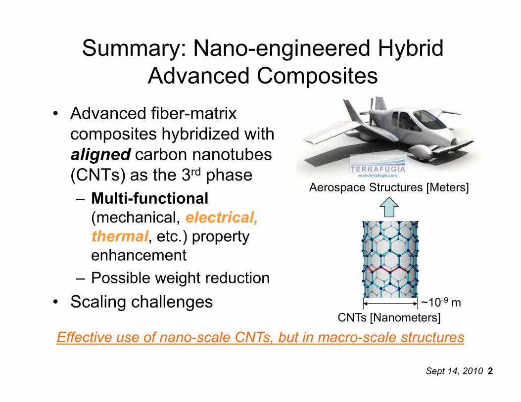
Summary: Nano-engineered Hybrid Advanced Composites
• Advanced fiber-matrix composites hybridized with aligned carbon nanotubes (CNTs) as the 3rd phase– Multi-functional
Aerospace Structures [Meters]
Sept 14, 2010 22
– Multi-functional(mechanical, electrical, thermal, etc.) property enhancement
– Possible weight reduction
• Scaling challenges ~10-9 mCNTs [Nanometers]
Effective use of nano-scale CNTs, but in macro-scale structures
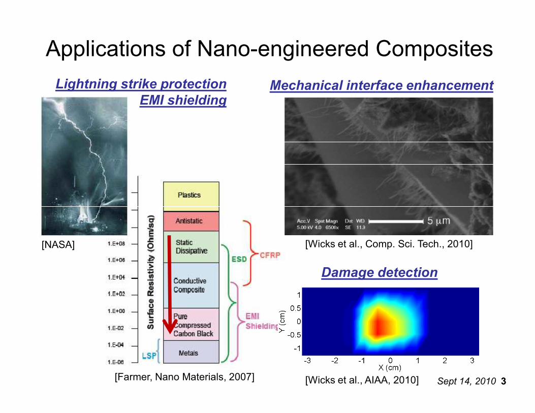
Applications of Nano-engineered CompositesLightning strike protection
EMI shieldingMechanical interface enhancement
Sept 14, 2010 33[Farmer, Nano Materials, 2007]
[NASA]
Damage detection
[Wicks et al., AIAA, 2010]
[Wicks et al., Comp. Sci. Tech., 2010]
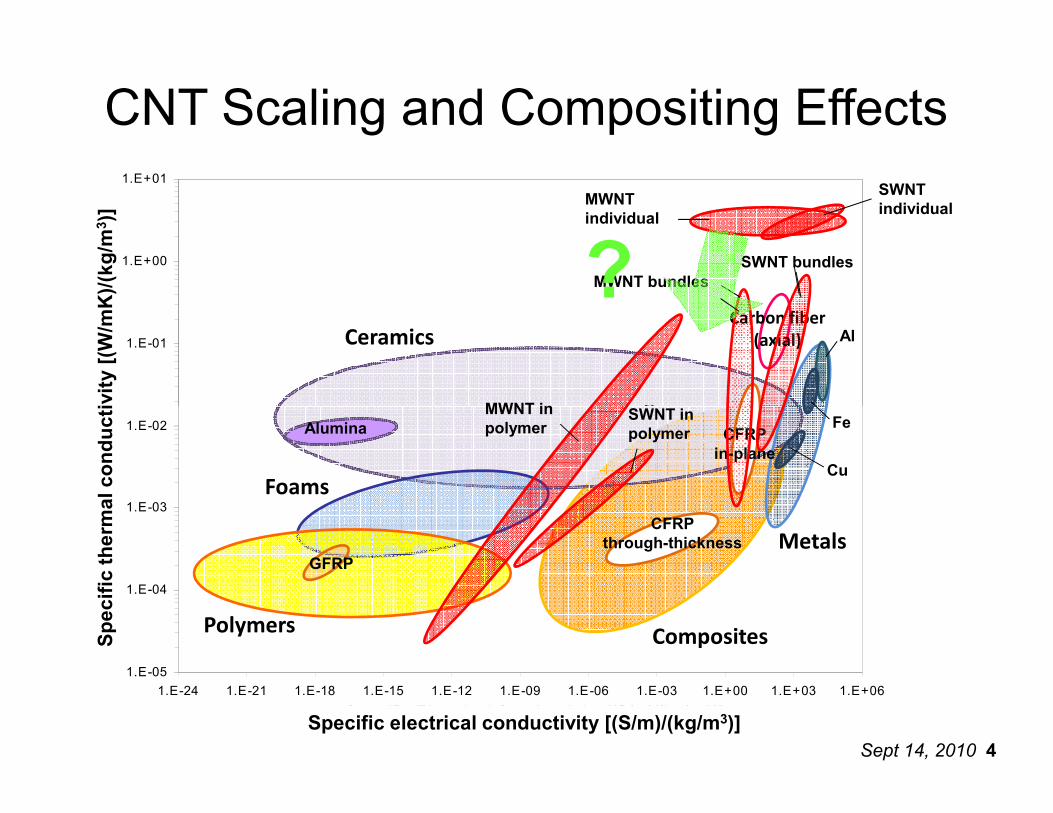
1.E-01
1.E+00
1.E+01
Specific Thermal Conductivity [(W/mK)/(kg/m3)]
Metals
A luminum
Steel
Copper
Ceramic
Compos
CFRP In-
CFRP Th
GFRP
Polymers
Polymer
Ceramics
MWNT individual
Carbon fiber (axial)
SWNT individual
Al
Specific thermal conductivity [(W/mK)/(kg/m
3 )]
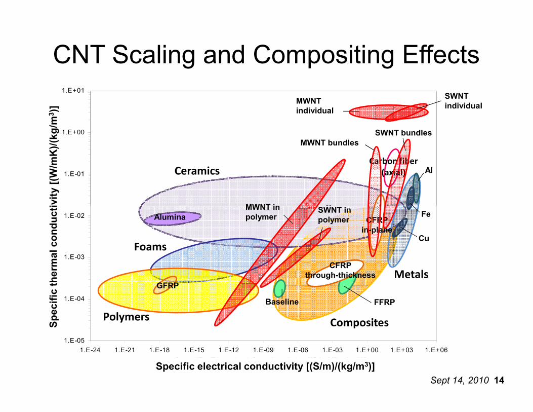
CNT Scaling and Compositing Effects
MWNT bundles
MWNT in
SWNT bundles
SWNT in
?
Sept 14, 2010 4
1.E-05
1.E-04
1.E-03
1.E-02
1.E-24 1.E-21 1.E-18 1.E-15 1.E-12 1.E-09 1.E-06 1.E-03 1.E+00 1.E+03 1.E+06
Specific Electrical Conductivity [(S/m)/(kg/m3)]
Specific Thermal Conductivity [(W/mK)/(kg/m3)]
SWNT in
MWNT in
SWNT b
MWNT b
SWNT in
MWNT in
Baseline
FFRP TT
Alumina
Carbon
CF
Series23
Series24
Metals
Foams
Polymers Composites
GFRP
Alumina CFRP in-plane
CFRP through-thickness
Fe
Cu
Specific electrical conductivity [(S/m)/(kg/m3)]
Specific thermal conductivity [(W/mK)/(kg/m
MWNT in polymer
SWNT in polymer
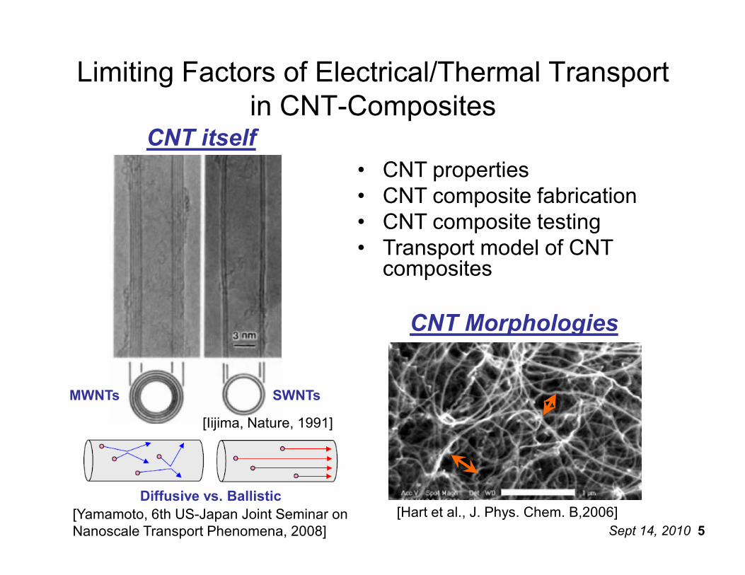
Limiting Factors of Electrical/Thermal Transport in CNT-Composites
CNT itself• CNT properties• CNT composite fabrication• CNT composite testing• Transport model of CNT composites
Sept 14, 2010 5
[Iijima, Nature, 1991]
[Yamamoto, 6th US-Japan Joint Seminar on Nanoscale Transport Phenomena, 2008]
MWNTs SWNTs
CNT Morphologies
[Hart et al., J. Phys. Chem. B,2006]Diffusive vs. Ballistic
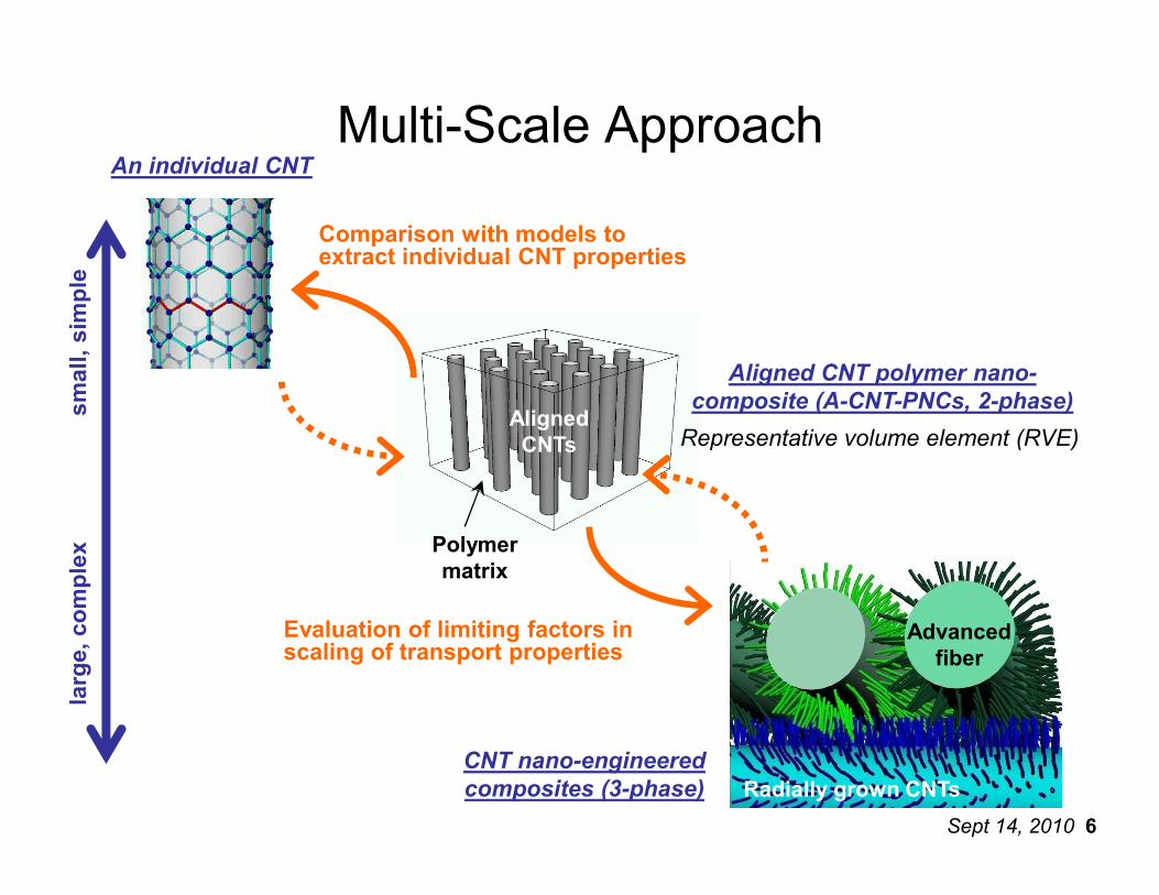
Aligned CNTs
Aligned CNT polymer nano-composite (A-CNT-PNCs, 2-phase)
Representative volume element (RVE)
Multi-Scale ApproachAn individual CNT
small, simple
Comparison with models to extract individual CNT properties
Sept 14, 2010 6
CNTs
Polymer matrix
Representative volume element (RVE)
Radially grown CNTs
Advanced fiber
CNT nano-engineered composites (3-phase)
large, complex
Evaluation of limiting factors in scaling of transport properties
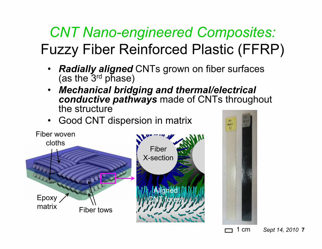
CNT Nano-engineered Composites:Fuzzy Fiber Reinforced Plastic (FFRP) • Radially aligned CNTs grown on fiber surfaces (as the 3rd phase)
• Mechanical bridging and thermal/electrical conductive pathways made of CNTs throughout the structure
• Good CNT dispersion in matrix
Sept 14, 2010 7
Fiber tows
Aligned CNT forest
Fiber woven cloths
Epoxy matrix
FiberX-section
• Good CNT dispersion in matrix
1 cm
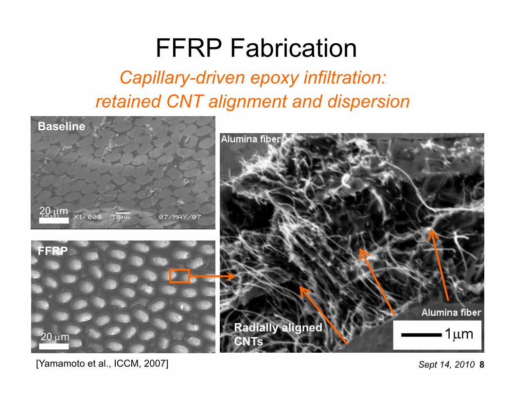
FFRP FabricationCapillary-driven epoxy infiltration:
retained CNT alignment and dispersionBaseline
Sept 14, 2010 8
FFRP
20 µm
20 µmRadially aligned CNTs
[Yamamoto et al., ICCM, 2007]
1.E-02
1.E+00
1.E+02
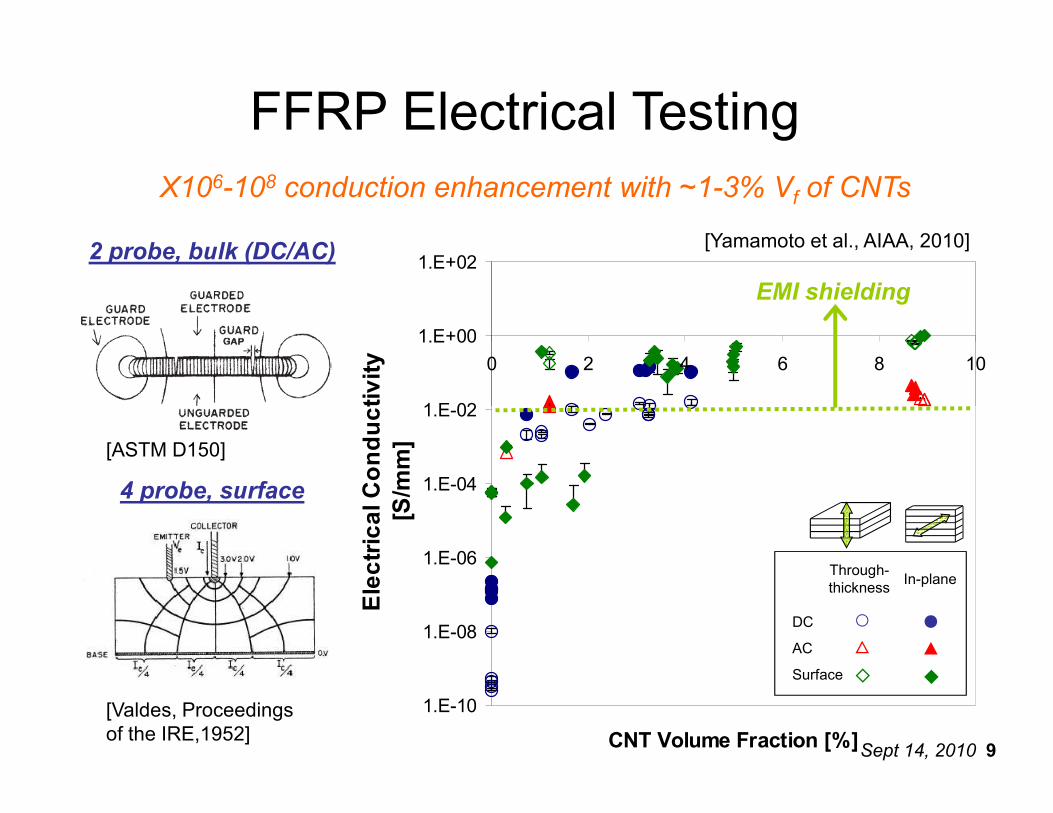
0 2 4 6 8 10Electrical Conductivity
FFRP Electrical TestingX106-108 conduction enhancement with ~1-3% Vf of CNTs
EMI shielding
2 probe, bulk (DC/AC) [Yamamoto et al., AIAA, 2010]
Sept 14, 2010 9
1.E-10
1.E-08
1.E-06
1.E-04
1.E-02
CNT Volume Fraction [%]
Electrical Conductivity
[S/mm][ASTM D150]
[Valdes, Proceedings of the IRE,1952]
DC
AC
Surface
Through-thickness In-plane
4 probe, surface
0.6
0.8
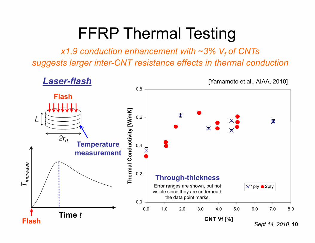
Thermal Conductivity [W/mK]
FFRP Thermal Testingx1.9 conduction enhancement with ~3% Vf of CNTs
suggests larger inter-CNT resistance effects in thermal conduction
Laser-flash
Flash
L
[Yamamoto et al., AIAA, 2010]
Sept 14, 2010 10
0.0
0.2
0.4
0.0 1.0 2.0 3.0 4.0 5.0 6.0 7.0 8.0
CNT Vf [%]
Thermal Conductivity [W/mK]
1ply 2ply
Through-thicknessError ranges are shown, but not visible since they are underneath
the data point marks.
Time t
Tin
crea
se
Flash
2r0
L
Temperature measurement
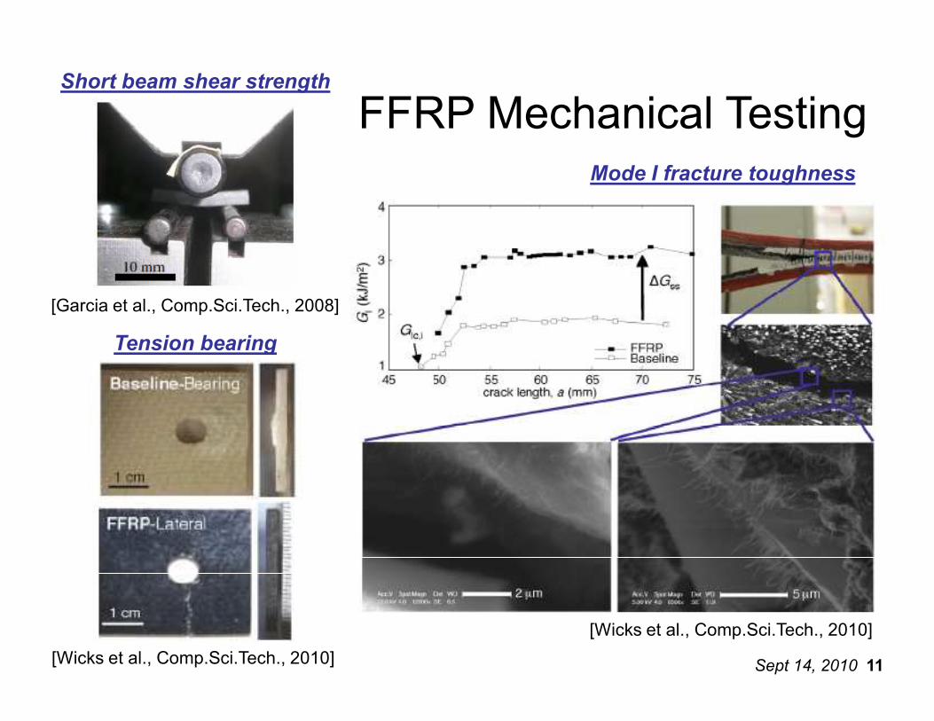
FFRP Mechanical TestingShort beam shear strength
Tension bearing
Mode I fracture toughness
[Garcia et al., Comp.Sci.Tech., 2008]
Sept 14, 2010 11
[Wicks et al., Comp.Sci.Tech., 2010]
[Wicks et al., Comp.Sci.Tech., 2010]
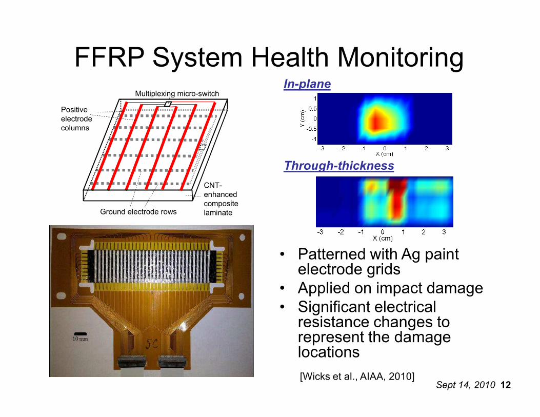
FFRP System Health MonitoringMultiplexing micro-switch
CNT-enhanced composite laminate
Positive electrode columns
Ground electrode rows
In-plane
Through-thickness
Sept 14, 2010 12
laminateGround electrode rows
• Patterned with Ag paint electrode grids
• Applied on impact damage• Significant electrical resistance changes to represent the damage locations[Wicks et al., AIAA, 2010]
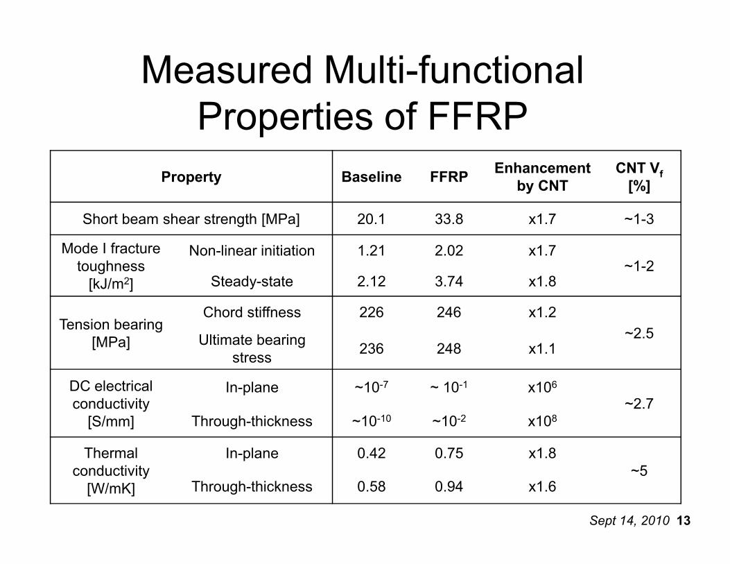
Property Baseline FFRPEnhancement
by CNTCNT Vf[%]
Short beam shear strength [MPa] 20.1 33.8 x1.7 ~1-3
Mode I fracture toughness [kJ/m2]
Non-linear initiation 1.21 2.02 x1.7~1-2
Steady-state 2.12 3.74 x1.8
Measured Multi-functional Properties of FFRP
Sept 14, 2010 13
[kJ/m2] Steady-state 2.12 3.74 x1.8
Tension bearing [MPa]
Chord stiffness 226 246 x1.2~2.5Ultimate bearing
stress236 248 x1.1
DC electrical conductivity [S/mm]
In-plane ~10-7 ~ 10-1 x10⁶~2.7
Through-thickness ~10-10 ~10-2 x10⁸
Thermal conductivity [W/mK]
In-plane 0.42 0.75 x1.8~5
Through-thickness 0.58 0.94 x1.6
1.E-01
1.E+00
1.E+01
Specific Thermal Conductivity [(W/mK)/(kg/m3)]
Metals
A luminum
Steel
Copper
Ceramic
Compos
CFRP In-
CFRP Th
GFRP
Polymers
Polymer
Ceramics
MWNT individual
Carbon fiber (axial)
SWNT individual
Al
Specific thermal conductivity [(W/mK)/(kg/m
3 )]
CNT Scaling and Compositing Effects
MWNT bundles
MWNT in
SWNT bundles
SWNT in
Sept 14, 2010 14
1.E-05
1.E-04
1.E-03
1.E-02
1.E-24 1.E-21 1.E-18 1.E-15 1.E-12 1.E-09 1.E-06 1.E-03 1.E+00 1.E+03 1.E+06
Specific Electrical Conductivity [(S/m)/(kg/m3)]
Specific Thermal Conductivity [(W/mK)/(kg/m3)]
SWNT in
MWNT in
SWNT b
MWNT b
SWNT in
MWNT in
Baseline
FFRP TT
Alumina
Carbon
CF
Series23
Series24
Metals
Foams
Polymers Composites
GFRP
Alumina
FFRPBaseline
CFRP in-plane
CFRP through-thickness
Fe
Cu
Specific electrical conductivity [(S/m)/(kg/m3)]
Specific thermal conductivity [(W/mK)/(kg/m
MWNT in polymer
SWNT in polymer
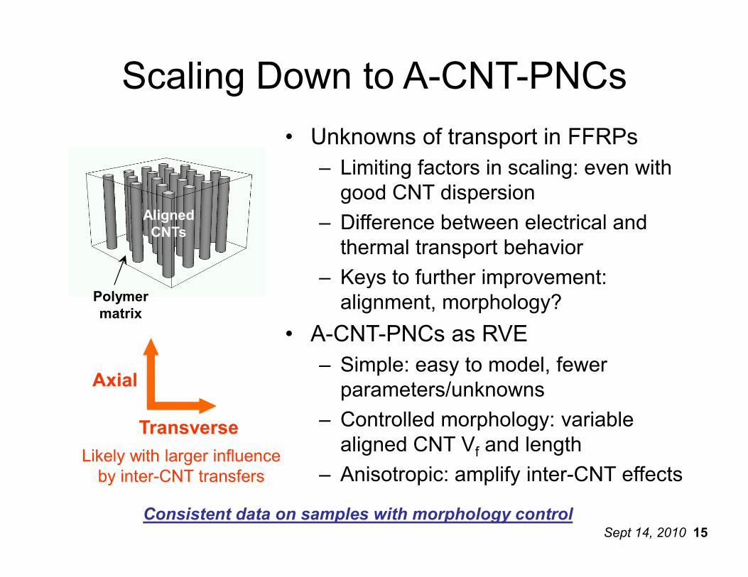
Scaling Down to A-CNT-PNCs• Unknowns of transport in FFRPs
– Limiting factors in scaling: even with good CNT dispersion
– Difference between electrical and thermal transport behavior
– Keys to further improvement:
Aligned CNTs
Polymer
Sept 14, 2010 15
Axial
Transverse
alignment, morphology?
• A-CNT-PNCs as RVE– Simple: easy to model, fewer parameters/unknowns
– Controlled morphology: variable aligned CNT Vf and length
– Anisotropic: amplify inter-CNT effectsLikely with larger influence by inter-CNT transfers
Consistent data on samples with morphology control
Polymer matrix
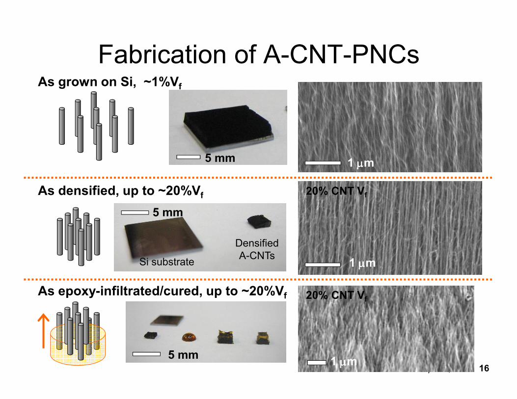
Fabrication of A-CNT-PNCsAs grown on Si, ~1%Vf
As densified, up to ~20%Vf 20% CNT Vf
1 µµµµm5 mm
Sept 14, 2010 16
1 µµµµmSi substrate
Densified A-CNTs
5 mm
5 mm
As epoxy-infiltrated/cured, up to ~20%Vf
1 µµµµm
20% CNT Vf
Contributions and Future Work
• Conclusions– Aligned CNTs as 3rd phase (2nd fiber) provides concomitant mechanical, thermal, and electrical enhancement
– Limiting factors in thermal and electrical transport were identified and quantified through characterization of A-CNT-PNCs.
Sept 14, 2010 17
CNT-PNCs.
• Future Work– Composite processing: CNT growth on carbon fibers, infusion with aero-grade epoxy
– Further FFRP characterization: mechanical and thermoelectrical properties, focusing on anisotropy due to aligned-CNTs
Collaboration with- Prof. Gang Chen, Kimberlee Collins (MechE, MIT)- Prof. Carl Thompson, Robert Mitchell (DMSE, MIT)- Prof. Kenneth Goodson, Amy Marconnet, Matt Panzer (MechE, Stanford)Helpful discussions from- TELAMS laboratory and NECST team (Aero/Astro, MIT)Technical assistance from- John Kane (Aero/Astro, MIT) - Prof. Harry Tuller, WooChul Jung, George D. Whitfield (DMSE, MIT)
Thank you!
- Prof. Harry Tuller, WooChul Jung, George D. Whitfield (DMSE, MIT)- Dave Terry, Kurt Broderick (MTL, MIT)- Patrick Boisvert, Yin-lin Xie (CMSE, MIT) - Amy L. Tatem-Bannister (ISN, MIT)
Questions to [email protected]
This work was supported by Airbus S.A.S., Boeing, Embraer, Hexcel, Lockheed Martin, Saab AB, Spirit AeroSystems, Textron Inc., Composite Systems Technology, and TohoTenax through MIT’s Nano-Engineered Composite aerospace STructures (NECST) Consortium, and by the Linda and Richard (1958) Hardy Fellowship.


![NANO EXPRESS Open Access Flow-induced voltage ......liquid [1]. Similar experiments were conducted with multi-walled carbon nanotubes (MWCNTs) [3]. The aligned MWCNTs were found to](https://img.pdfslide.us/doc/110x75/60cc1ccfc265ec2fa524fd51/nano-express-open-access-flow-induced-voltage-liquid-1-similar-experiments.jpg)

![Aligned Small Diameter Single-Walled Carbon Nanotube ...bxw109120/QE_Proposal_BlakeWilson.pdf · The first single walled carbon nanotubes were reported two years later in 1993 [13]](https://img.pdfslide.us/doc/110x75/5b14d3727f8b9a8f548c391a/aligned-small-diameter-single-walled-carbon-nanotube-bxw109120qeproposalblakewilsonpdf.jpg)