Embed Size (px)
Citation preview
Journal of Engineering Volume 18 August 2012 Number 8
924
The Effect of Laminated Layers on the Flutter Speed of Composite Wing
Asst. Prof. Dr.Ahmed Abd Al-Hussain Ali Mohammed Ismael Hamed .
Baghdad University, Mechanical Engineering Department.
Abstract
The paper presents an investigation to the flutter speed of composite wing for different ply orientation .Structurally the composite wing was idealized as a composite beam load carrying structure. Theodorsen’s expression was used to get the 2- dimension unsteady lifting force and pitching moment in the limit of incompressible flow and subsonic speed which were integrated over the wing span. A free vibration analysis was first carried out to get the natural frequencies and mode shapes .The velocity-damping (V-g) method was used to calculate the flutter speed and the flutter frequency. A wing of unmanned aerial vehicle was manufactured from woven glass and polyester resin where the flutter speed was calculated experimentally by the wind tunnel test .The flutter speed was calculated analytically for different ply orientation, it is found that the increasing in torsion rigidity leads to increase in the flutter speed, the fiber combination with high torsion rigidity and relatively low coupling rigidity give higher flutter speed.
Keywords: flutter, composite wing, aeroelastic tailoring.
ةالخالص
اح ة للجن ى سرعة الرفرف من حيث . من خالل هذا البحث تم معرفة تأثير إتجاه األلياف للمواد المرآبة التي تستخدم في صناعة اجنحة الطائرات علواء قوة الرفع وعزم اال.تم التعامل مع الجناح على انه عتبة مرآبة تقاوم االحمال المسلطة على الجناح ، مقاومة االحمال المسلطة سبت لمقطع لت ٌح
ل من سرعة جناح ثنائي األبعاد باستخدام صيغة ثيوديرسون لحساب قوة الرفع وعزم االلتواء المتغير مع الزمن لجريان غير انضغاطي وسرعة اقددي اح باستخدام التكامل الع اح المرآب لغرض . الصوت ومن ثم حسبت على طول الجن زاز الحر للجن ل االهت م دراسة وتحلي رددات ت حساب الت
سرعة ( إسٌتخدَمت طريقة .الطبيعية وأشكال التشوه اح ) عامل التضاؤل –ال ة للجن ردد الرفرف اح مرآب لطائرة .لحساب سرعة وت صنيع جن م ت تة حسبت سرع . بدون طيار من مادة الياف الزجاج المنسوج مع مادة البولستر حيث إن سرعة الرفرفة حسبت عمليًا باستخدام النفق الهوائي ة الرفرف
ة نظريا ادة سرعة الرفرف ى زي ذي ,لعدة اتجاهات لاللياف ،من خالل نتائج البحث تبين بان زيادة صالدة االلتواء يؤدي ال اف ال اه لاللي ان افضل اتج .تواء نوعا ما واطئةاالل-من خالله نحصل على سرع رفرفة عالية هو االتجاه الذي ينتج عنه صالدة التواء عالية مع صالدة ازدواج االنحناء

The Effect of Laminated Layers On The Flutter Speed Of Composite Wing
Dr.Ahmed Abd Al-Hussain Ali Mohammed Ismael Hamed
925
1. Introduction
The aircraft industry utilized a great deal of composite materials due to the opportunities they present for weight saving. Their share in aircraft applications has reached more than 15%of the structural weight of aircraft, and more than50%of the structural weight of helicopters and fighter aircraft for the last 40 years. In structural applications such as wing configurations, composite materials are popular choices because of additional advantage of tailoring their stiffness’s to the directions of loading. This is especially critical when the wing interacts with the surrounding airflow, resulting in structural deformations, known as aeroelastic effects, which can be detrimental to the performance and stability of an aircraft. At high speeds , these deformations can exceed structural stiffness of the material and result in structural failure.
(Banerjee2000 ) ,investigated the flutter behavior of uniform composite wings. The wing is idealized as a bending torsion (materially)coupled composite beam with cantilever end condition for which the frequency equation and mode shapes in free vibration are presented in closed analytical form. The flutter problem is formulated by summing algebraically the expressions for generalized mass, generalized stiffness and generalized aerodynamic force terms. From the final expression containing all the above terms the flutter speed and flutter frequency are determined by using a standard root finding procedure .(Guo et al.,2003 ), presented an analytical study on optimization of a laminated composite wing structure for achieving a maximum flutter speed and a minimum weight without strength penalty. The attention has been paid mainly to the effect on flutter speed of the bending, torsion and, more importantly , the bending-torsional coupling rigidity, which is usually associated with asymmetric laminate lay-up. (Attaran et al.,2006), studied the effects of aspect ratio, sweep angle, and stacking sequence of laminated composites to find the optimized configuration of an aeroelastically tailored composite wing idealized as a flat plate in terms of flutter speed. To study the effect of stacking sequence the classical lamination theory (CLT) has been chosen. (Masaki Kameyama et al.,2007): treated the flutter and divergence characteristics of composite plate wings with various sweep angles. The effect of laminate configuration on the flutter and
divergence characteristics is investigated for composite plate wings. To examine the effect of laminate configuration , the flutter and divergence characteristics are represented on the lamination parameter plane. (Guo,2007), presented an investigation into a minimum weight optimal design and aeroelastic tailoring of an aerobatic aircraft wing structure . Based on a minimum weight composite wing box model of adequate strength the investigation was focused on the aeroelastic tailoring of the wing box by employing the gradient-based deterministic optimization method . (Dayang Laila et al.,2008): studied aeroelastic tailoring characteristics of a cantilevered composite wing ,idealized as a composite flat plate laminate .The composite laminate was made from woven glass fibers with epoxy matrix .Aeroelastic wind tunnel testing of the laminate was performed and the flutter speed and the flutter frequency were calculated experimentally. (Daniel et al.2010): introduced an aeroelastic tailoring approach using lamination parameters optimization. The main goal of this research is to analyze a composite plate wing subject to aeroelastic effects and the improvement in flutter speed by means of eigen frequency maximization. (Majid et al., 2011) : investigated the aeroelastic flutter of laminated hybrid composite wing .The composite wing was modeled as composite plates and aeroelastic analysis has been carried out in the frequency domine . Pre-determined fiber orientation of 3-layer carbon/epoxy and glass/epoxy laminated plate has been employed with various aspect ratios. 2. Free Vibration Analysis
A composite wing that exhibits both geometric and material coupling is shown in Fig. 1. The elastic axis, which coincides with the Y-axis is chosen to be the locus of the geometric shear centers of the wing cross-section. It is allowed to deflect out of the plane by h(y,t) whilst the cross-section is allowed to rotate about OY by ψ(y,t) where y and t denote distance from the origin and time, respectively. The wing has a length of L , bending rigidity EI, torsional rigidity GJ, bending–torsion coupling rigidity K , mass per unit length m , and mass moment of inertia per unit length Iα about the Y-axis( Iα=Ic.g+mxα2)., respectively . In the figure, xα is the distance
Journal of Engineering Volume 18 August 2012 Number 8
926
between the mass and elastic axes, which are, respectively, the loci of the mass centre
(centroid) and the shear centre of the wing cross-sections, and is positive when the mass axis is after the elastic axis as shown. The two principal parameters that are responsible for the geometric and material coupling are xα and K, respectively. The governing differential equations of the free vibration motion of composite wing shown in Fig.1 ,are given by (Banerjee2007 );
02
2
2
2
3
3
4
4
=∂
−∂
+∂
+∂
∂∂∂∂txtyy
mh
mKh
EIψψ
α
(1)
02
2
2
2
3
3
2
2
=∂
+∂
−∂
+∂
∂∂∂∂txtIyyh
mh
KGJαα
ψψ
(2)
Assuming harmonic osillation so that ;
e tiyHtyh ω)(),( = (3)
e tiyty ωψ )(),( Ψ= (4)
Where(ω) is the frequency of oscillation ,H and Ψ are the amplitudes of (h) and (ψ) respectively .the solution of eqs. (1) and (2) gives;
γζγζβζ
βζαζαζζ
sincossin
cossinhcosh)(
654
321
AAAAAAH
+++
++=
(5)
γζγβζ
βζαζαζζ
sincossin
cossinhcosh)(
654
321
BBBBBB
+++
++=Ψ
(6)
Where (ζ ) is the normalized length LY
=ζ .
A1-A6 and B1-B6 are constants, which are determined by applying the boundary conditions .The expressions for the bending rotation
Θ(ζ),shear force S(ζ), bending moment M(ζ)and torque T(ζ) are respectively as follows;
ζζ
ddH
LdydH 1)( ==Θ (7)
ζζζ 2
2
23
3
3)(d
K
d
HEIS dL
dL
Ψ+= (8)
ζζ
ζ dd
LK
d
HEIM dL
Ψ−−= 2
2
2)( (9)
ζζ
ζ dd
LGJ
d
HKT dL
Ψ−−= 2
2
2)( (10)
For a cantilever wing , the fixed –free boundary conditions require that (Wang 2004):
At the fixed end, y=0 → ζ =0;
0)0()0()0( =Ψ=Θ=H (11)
At the free end ,y=L → ζ=1 ;
0)1()1()1( === TSM (12)
Substitute eq.(11) into eqs.(5,6 and 7) and eq.(12) into eqs.(8,9 and 10), we can get the characteristic equation;
[ ] 0=Λ A (13)
Where A=[A1 A2 A3 A4 A5 A6 ]T ,[Λ] is a 6×6 characteristic matrix being function of the natural frequency .The natural frequencies can be obtained by solving;
[Λ]=0 (14)
In the present work eq.(14) was solved numerically by the secant method with (MATLAB 6.5) program .Substituting the natural frequency back into eq.(13) to compute the mode shape.
3. Structural Model of the Composite Wings
In the present work, the structural model of the composite wing ,is a laminated beam load carrying structure. The leading and trailing edges were only counted in calculating the mass ,inertia
The Effect of Laminated Layers On The Flutter Speed Of Composite Wing
Dr.Ahmed Abd Al-Hussain Ali Mohammed Ismael Hamed
927
and aerodynamic loads .The effective rigidities for a laminated beam shown in Fig.2 are as follows(Stephan 2010);
⎟⎟⎠
⎞⎜⎜⎝
⎛−=
⎟⎟
⎠
⎞
⎜⎜
⎝
⎛−=
⎟⎟
⎠
⎞
⎜⎜
⎝
⎛−=
DDDD
DDD
DDD
dK
dGJ
dEI
11
161226
11
216
66
11
212
22
2
4 (15)
Where(d) is the chord of the laminate in (m) .
Dij can be expressed as (NASA 1994);
[ ]⎟⎟
⎠
⎞
⎜⎜
⎝
⎛+= ∑
=zttQD kk
kN
k kij ij
23
1 12 (16)
21hhz kk
k+
+= (17)
Where
zk is the distance from the geometric midplane to the center of the kth ply in (m) . N :number of layers. tk : the thickness of the kth ply in (m) . Qij
:lamina stiffness in (N/m2).
4. Generalized Mass and Generalized Stiffness
The generalized mass and generalized stiffness are derived from the theory of the normal mode and orthogonality relation by following the procedure of [ Thomson 1997],the expression for the generalized mass (Mi) and generalized stiffness (ki) in the i-th mode of the cantilever wing ,respectively are as follows;
ζααdmm iiiii IHxHM )2( 2
1
0
2 ΨΨ∫ +−=
(18)
Mk iii ω2= (19)
Where Hi , Ψi and ωi are natural bending mode,torsion mode and the natural frequency respectively.
5. Unsteady Aerodynamic Load on Two Dimensional Airfoil
Fig.3 shows a strip of unit span in incompressible flow, the airfoil has two degree of freedom a vertical translation (h) called bending positive upward ,and a rotation (ψ),called pitching ,positive if leading edge nose up about the elastic axis which is located at distance (ab) from the mid chord, where (b) is the semi chord , (a) being positive toward the trailing edge . The Theodersen's expression for the unsteady lifting force and pitching moment about the elastic axis can be expressed as follows(Hodges and pierce 2009);
)(
])21()[(2
2 ψψπρ
ψψπ
&&&&&&
&&
bahV
abhVkVbCL
b −−+
−+−=
])81()
21([
])21()[()
21(2
222
2
ψψπρ
ψψπρ
&&&&&
&&
abb
bhbaaVb
abhVkCaVM
+++−−
−+−+=
(21)
k: reduced frequency parameter,Vbk ω
= (22)
V: air speed (m/s). ω : frequency of oscillation (rad/s). b: semi chord (m). a: elastic axis location from the mid chord(m/m). ρ: air density (kg/m3).
C(k): Theodersen Function can be expressed as (Zhanming 2001);
)32
3
2
32
3
2
481481.2934530.0089318.0(
)000146.0
122397.0327214.0001995.0(
)035378.1251239.0021508.0(
)500502.0
512607.0210400.0021573.0(
)(
kkk
k
kkk
k
k
k
ik
k
kC
+++
+++
−
+++
+
++
=
Journal of Engineering Volume 18 August 2012 Number 8
928
(23)
6. Generalized Aerodynamic Coefficients
The generalized aerodynamic force and moment of the cantilever wing had been formulated by the principle of the virtual work .The generalized aerodynamic forces can be expressed as follows ( Mayuresh J.Patil 1997 );
{ } [ ] [ ][ ] { } [ ]{ }qQAqdAQT
ωω ζ 21
0
2 =Φ= ∫ Φ
(23)
Or eq.(23) can be expressed as (Banerjee 2000);
ζdjiji
ijjiij
AHAHAHHAQ)
(
2221
12
1
011
ΨΨΨ
Ψ∫++
+= (24)
Where
])5.0(8
))5.0(1)(()5.0(2[
])5.0()(2[
))]5.0(1)((2)[(
))(2(
222
2
42
22
22
32
21
22
32
12
22
22
11
ika
aikkCa
aaikkC
aikkCika
ikkC
akkkbA
kkbA
kkbA
kkbA
−+++
+++=
−+−=
−+++=
+−−=
ω
ω
ω
ω
πρ
πρ
πρ
πρ
(25)
7. Formlation of The Flutter Problem
Lagrange equation of motion can be written in the form(Mayuresh J.Patil 1997);
}]{[}]{[}]{[ 2 qQAqKqM ω=+&& (26)
Where
[M] and [K] are n×n diagonal matrices of generalized mass and generalized stiffness (with i-th diagonal representing Mi and ki ) ,[QA] is the complex n×n generalized aerodynamic matrix.
8. Structural Damping
The eq. (26) gives the equation of motion of a wing in an airstream. But, the aerodynamic model chosen, is valid only for simple harmonic motion. So to force the system to undergo Harmonic oscillations, an artificial structural damping term is added. The structural damping is known as to be a force proportional to the displacement but in-phase with velocity. For a system undergoing simple harmonic motion ,the structural damping force (FD=i×constant =igK) ,where (K) is stiffness and (g) is an artificial structural damping .Adding artificial structural damping to our system ,eq.(26) becomes (Mayuresh J.Patil 1997);
( ){ } }{}{][][][ 1qqQAMK λ=+
− (27)
Where
ω
λ 2
)1( ig+= (28)
9. Solution Of The Flutter Equation
Eq.(27) is an eigenvalue problem which represent the flutter equation to be solved ,in the present work ,the velocity-damping (V-g) method had been used to compute the flutter speed and the flutter frequency with (MATLAB 6.5) program.
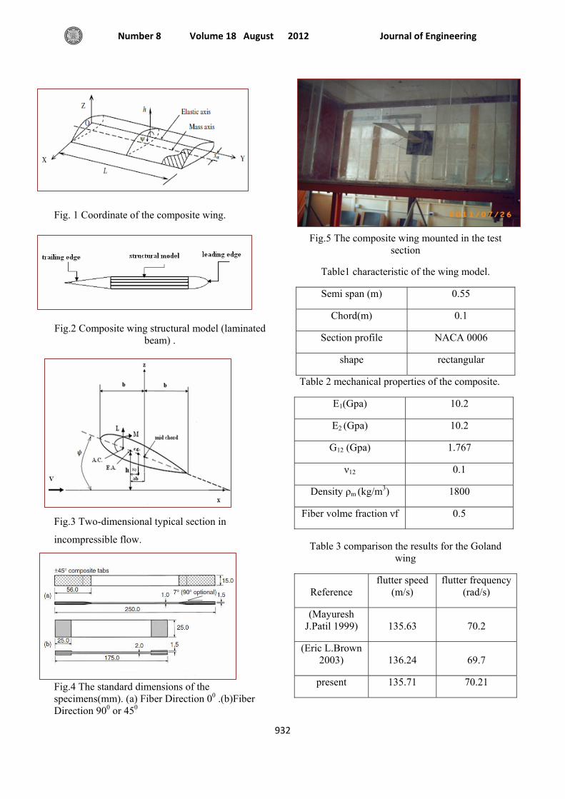
10. Experimental Work First , a tensile specimens was manufactured according to ASTM D3039 standard dimensions(ASTM International 2011) to calculate the mechanical properties of the laminate .Fig .4 shows the dimensions of the specimens. The composite wing was manufactured from woven glass fiber and polyester resin within a dimensions that are suitable to the wind tunnel test section of the mechanical engineering department of Baghdad University.Fig.5 shows the wing mounted in the test section.
The Effect of Laminated Layers On The Flutter Speed Of Composite Wing
Dr.Ahmed Abd Al-Hussain Ali Mohammed Ismael Hamed
929
Two strain gauges aligned in spanwise and 45° direction had been used to obtain bending and torsional strains, respectively which were attached at the root of the wing and connected to interfacing system work with visual basic program to display the bending and torsion response of the wing on the monitor of the computer .The air speed in the wind tunnel was calculated by using Manometer and Pitot static tube .Bernoulli equation is applied between two point in the test section ,thus the air speed can be calculated from the following relation;
ρρ
a
whV g12= (29)
Where the subscript w,a represent water and air respectively. ρ : density (kg/m3). g1 : gravity acceleration (m/s2). h : water head (m) of the Manometer.
10.Results
The wing of (Suleman 2007) was scaled by(1/2.2),Table 1 show the characteristics of the wing of the present work.
10.1 Material Properties of the Wing
The mechanical properties of the composite were calculated by the tensile test and stated in Table 2.
10.2 Validity of the Test Procedure
Table 3 shows the comparison of the flutter speed and the flutter frequency for the Goland wing.
10.3 The Effect of Ply Orientation on the Flutter Speed
The structural model is a composite beam load carrying structure . This composite beam was stacked for different ply orientation and the flutter speed was computed for each ply . The properties of the manufactured composite wing are;
Width of the beam d = 60.5 mm. Thickness of the beam t = 4.24 mm. Number of layers N = 8 . Ply thickness tk = 0.53 mm. Mass of the wing m = 0.68 kg/m . Polar moment of inertia about the elastic axis Iα =
2.75 × 10⁻⁴ kg.m . Elastic axis location from the mid chord a =-0.39. Distance between elastic and mass axis xα = 9.5mm.
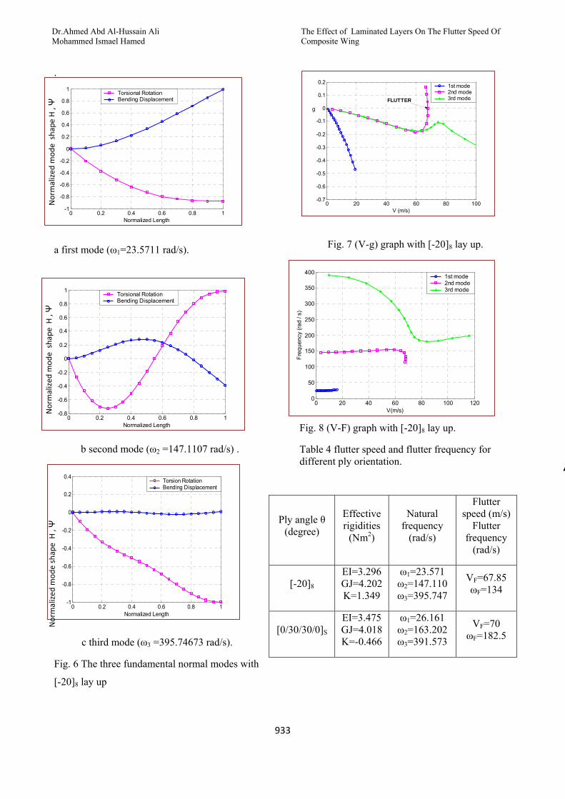
In the first ply ,all layers (8 layers) ,were orientated along common direction(θ=-20°),thus the first ply was [-20]8 , the natural frequencies at this ply and the corresponding normal mode shapes are shown in Fig. 6.
Substitute those three natural frequencies and mode shapes in the (V-g) method ,from Fig. 7 the flutter speed is (VF =67.85m/s) , and from Fig. 8 the flutter frequency is (ωF =134 rad/s).
The results of the flutter speed and the flutter frequency for different ply orientation are summarized in Table 4.
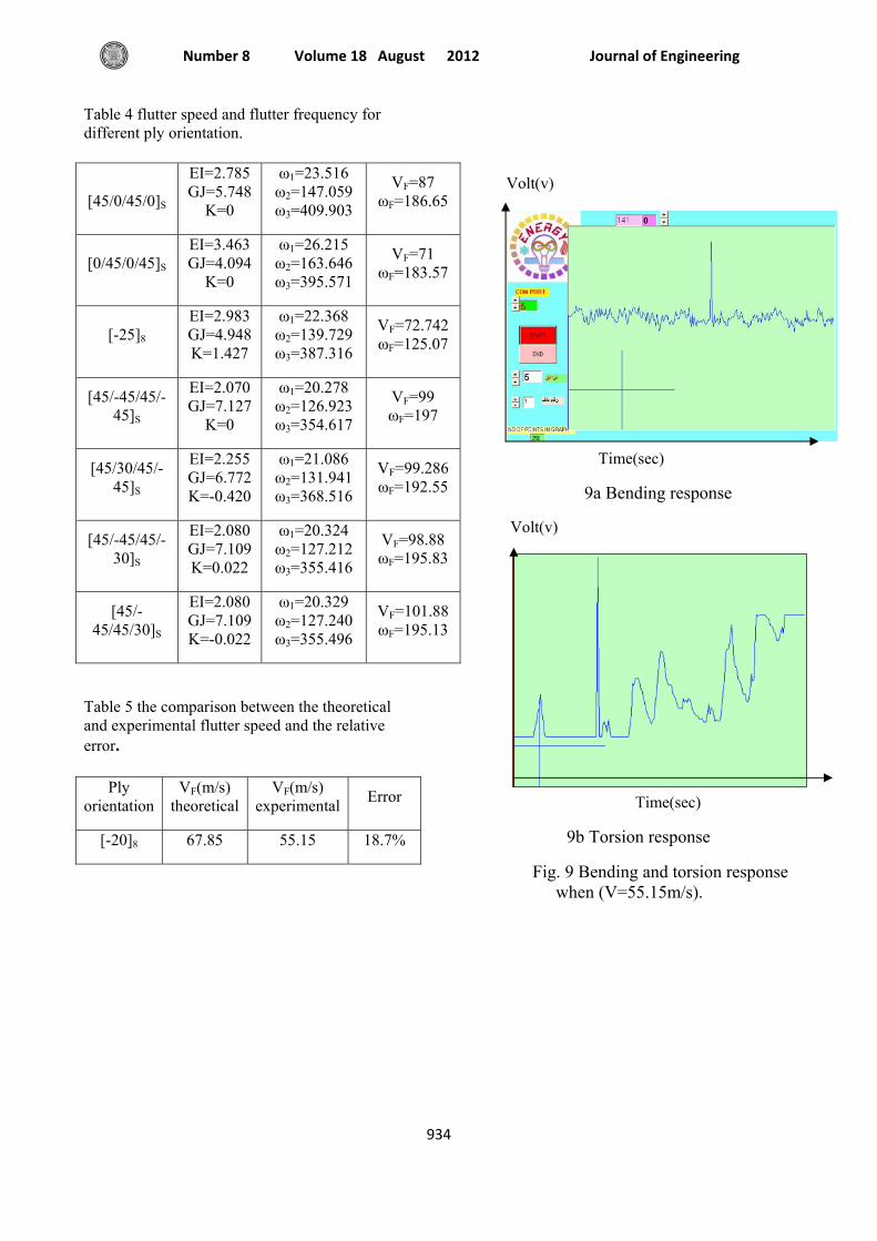
11. Experimental Flutter Results
Fig. 9 shows the response of the composite wing at air speed ( V=55.15 m/s) , it is obvious that the amplitude is with increasing with time history , this motion indicate the unstable case , so that this speed may be represent as a flutter speed .Table 5 states the comparison between the theoretical and experimental flutter speed and the relative error.
12. Discussion
From the free vibration results it is clear that the use of fibrous materials in the design of composite wing produce the bending- torsion coupling. In this analysis both the material and geometric coupling were taking into account . The results in Table 4 state that the stiffness of composite wing depend on the fiber direction with respect to reference line ,therefore may be obtain different values of bending rigidity ,torsion rigidity and coupling rigidity for different fiber orientation , also the location of the specific layer from the geometric mid plane is of major effect on the stiffness of the composite wing .
it is clear that the selection of fiber directions that increase in bending rigidity (which has maximum value when the fiber orientation(00 or 900)), attending it decreasing in torsional rigidity which leads to decreasing in the flutter speed. Also it is
Journal of Engineering Volume 18 August 2012 Number 8
930
to be evident that the torsional rigidity is of the greater effect on the flutter speed of the aircraft wing , thus the flutter speed may be increased by increasing the torsion rigidity which is reached it's maximum value when the fiber orientation (450 or -450) , while the fiber orientation (00 or 900) produce minimum torsional rigidity . It is may be conclude that the fiber direction (450 or -450) is preferable in the aeroelastic tailoring of composite wing because it is produce high torsional rigidity , as a results the flutter speed is increase. From the calculated results it is shown that the coupling rigidity reached its maximum value when the fiber orientation (250 or -250), while the bending and torsion are materially decoupled when the fiber orientation(450 or 00 or 900 or -450).The selection of fiber orientation that produce high coupling rigidity don’t attend it increase in the flutter speed . The ply [-25]8 has a maximum coupling rigidity , but at this ply the flutter speed is low in comparison with the flutter speed at another plies as shown in Table 4, despite that , the coupling rigidity has clear effect on the increasing in the flutter speed ,this effect may be shown in the two plies , the first [45/-45/45/-45]S has a flutter speed (VF=99m/s) and K=0 with higher torsional rigidity, the second [45/-45/45/30]S which has a flutter speed (VF=101.88m/s) and K=-0.022 Nm2. In this analysis the calculated results states that the best combination of ply orientations to increase the flutter speed, is the ply of high torsional rigidity with low minus coupling rigidity.
13. Conclusion
The main conclusions may be obtained from this study are;
1-The stiffness of composite wing depends on the fiber orientation , also the location of the individual layer from the geometric mid plane has the significant effect on the stiffness of composite wings.
2-For the woven E-glass in the case , the bending and torsion are decoupled when the ply angle is one of the four orientations ( while for the unidirectional fiber , the bending and torsion are decoupled when the fiber orientation (
3-The fiber orientation gives maximum bending rigidity, the fiber orientation
gives maximum torsion rigidity while the fiber orientation gives maximum coupling rigidity.
4-In comparison with the bending rigidity , both the torsional and the coupling rigidities have much more significant effect on the flutter speed of a composite wing .The torsional rigidity plays a relatively more dominant role in aeroelastic tailoring. Increasing in torsional rigidity leads to increase in the flutter speed.
5-The desirable combination of fiber orientations, relatively large torsional rigidities with a relatively small coupling rigidity, this combination will increase the flutter speed.
References Attaran " Structural Optimization of an Aero elastically Tailoring Composite Flat Plate Made of Woven Fiberglass/Epoxy ” Department of Aerospace of Engineering University Putra Malaysia , Jurnal Mekanikal , No. 22,p. 75-88 December, 2006.
ASTM International "D 3039-07 Standard test method for Tensile Properties of Polymer Matrix Composite Materials", 2011.
Banerjee " Flutter Analysis of COMPOSITE Wings Using Symbolic Computation" Department of Mechanical Engineering and Aeronautics, City University,2000 .
Banerjee" A dynamic stiffness element for free vibration analysis of composite beams and its application to aircraft wings". Department of Mechanical Engineering and Aeronautics, City University,2007.
Daniel " Aeroelastic Tailoring of Composite Plates Through Eigenvalues Optimization" Buenos Aires, Argentina, 2010.
Dayang Laila Abang Haji Abdul Majid ShahNor Basri “ LCO flutter of cantilevered woven
10
glass/epoxy laminate in subsonic flow” Department of Aerospace Engineering, Faculty of Engineering, Universiti Putra Malaysia ,2008.
Eric L.Brown "Integrated Strain Actuation In Aircraft With Highly Flexible Composite Wings"
The Effect of Laminated Layers On The Flutter Speed Of Composite Wing
Dr.Ahmed Abd Al-Hussain Ali Mohammed Ismael Hamed
931
Doctor of Philosophy thesis, Massachusetts Institute of Technology,2003.
Guo, Bannerjee and Cheung "The Effect of Laminate Lay-Up on the Flutter Speed of Composite Wings"journal of aerospace engineering,vol.207 No.3,p.115-122 June 2003.
Guo" Aeroelastic optimization of an aerobatic aircraft wing structure" Department of Aerospace Engineering, School of Engineering, Cranfield University UK, Aerospace Science and Technology (2007).
Güclü Seber " Flutter Analysis of a Tapered Wing Using Assumed Modes Method", 2009.
William T.Thomson , Marie Dillon and Chandramouli Padmanabhan "Theory of Vibration With Applications". Pearson, Fifth edition 2010.
Hodges and Pierce," Aeroelasticity" Georgia Institute of Technology, Atlanta, Georgia ,2009.
Mayuresh J.patil "Aeroelastic Tailoring of Composite Box Beam" Georgia Institute of Technology ,Atlanta ,Georgia , AIAA 1997.
Mayuresh J. Patil" Nonlinear Aeroelastic Analysis , Flight Dynamics ,and Control of a Complete Aircraft" Doctor of Philosophy thesis, Georgia Institute of Technology,1999.
Masaki Kameyama"Optimum design of composite plate wings for aeroelastic characteristics using lamination parameters"computer and structure,(2007) .
Majid and Basri " Flutter Analysis of a Hybrid Plate-like Fiber-Reinforced composite wing" Department of Aerospace Faculty of Engineering Universiti Putra Malaysia,2011.
NASA" Basic Mechanics of laminated composite plates" NASA reference publication 1351,1994.
Stephan Borneman" Calculating Effective Rigidities of a Laminated Composite Beam (Classical Laminate Theory)", 2010.
Suleman" Design and Testing of a Morphing Wing for an Experimental UAV" University of Victoria, Canada,2007.
Wang " Vibration Analysis of Cracked Composite Bending-torsion Beams for Damage Diagnosis"
Doctor of Philosophy thesis, university of Virginia,2004.
Zhanming Qin" Vibration and Aeroelasticity of Advanced Aircraft Wings Modeled as Thin-Walled Beams , Dynamics, Stability and Control "Doctor of Philosophy thesis, university of Virginia,2001.
Symbols
a :elastic axis location(-). d:chord of the laminate(m). EI:bending rigidity(Nm2). GJ:torsion rigidity(Nm2). K:coupling rigidity(Nm2). h:bending displacement(m). H: normalized bending mode(-). Ψ : normalized torsion mode (-). k:reduced frequency parameter(-). m:mass(kg). xα:mass axis location(m). Iα:polar moment of inertia(kg.m). hk:location of the layer from the geometric mid plain(m). V:air speed(m/s). L: wing length (semi span)(m). b:semi chord of the wing(m). g:artificial structural damping(-). g1:gravity acceleration(m/s2). ζ:normalized length(-). ω:frequency(rad/s). ψ:torsion rotation(rad). ρ:density(kg/m3). Θ(ζ):bending rotation(rad). S(ζ):shear force(N). M(ζ):bending moment(N.m). T(ζ): torque(N.m). H :amplitude(m) Ψ:amplitude(rad) A1….A6:constants
Qij
:lamina stiffness (N/m2).
zk is the distance from the geometric mid plane to the center of the kth ply in (m) . N :number of layers. tk : the thickness of the kth ply in (m) . A.C: aerodynamic center. E.A: elastic axis c.g.: center of gravity. ρw: water density(kg/m3). ρa: air density(kg/m3). g1: gravitational acceleration (m/s2). C(k): Theodersen function. q: generalized coordinates
Journal of Engineering Volume 18 August 2012 Number 8
932
Fig. 1 Coordinate of the composite wing.
Fig.2 Composite wing structural model (laminated beam) .
Fig.3 Two-dimensional typical section in
incompressible flow.
Fig.4 The standard dimensions of the specimens(mm). (a) Fiber Direction 00 .(b)Fiber Direction 900 or 450
Fig.5 The composite wing mounted in the test section
Table1 characteristic of the wing model.
Semi span (m) 0.55
Chord(m) 0.1
Section profile NACA 0006
shape rectangular
Table 2 mechanical properties of the composite.
E1(Gpa) 10.2
E2 (Gpa) 10.2
G12 (Gpa) 1.767
ν12 0.1
Density ρm (kg/m3) 1800
Fiber volme fraction νf 0.5
Table 3 comparison the results for the Goland wing
Reference flutter speed
(m/s) flutter frequency
(rad/s)
(Mayuresh J.Patil 1999) 135.63 70.2
(Eric L.Brown 2003) 136.24 69.7
present 135.71 70.21
The Effect of Laminated Layers On The Flutter Speed Of Composite Wing
Dr.Ahmed Abd Al-Hussain Ali Mohammed Ismael Hamed
933
0 0.2 0.4 0.6 0.8 1-1
-0.8
-0.6
-0.4
-0.2
0
0.2
0.4
0.6
0.8
1
Normalized Length
Torsional RotationBending Displacement
Normalized
mod
e shape
H , Ψ
0 0.2 0.4 0.6 0.8 1-0.8
-0.6
-0.4
-0.2
0
0.2
0.4
0.6
0.8
1
Normalized Length
Torsional RotationBending Displacement
0 0.2 0.4 0.6 0.8 1-1
-0.8
-0.6
-0.4
-0.2
0
0.2
0.4
Normalized Length
Torsion RotationBending Displacement
0 20 40 60 80 100-0.7
-0.6
-0.5
-0.4
-0.3
-0.2
-0.1
0
0.1
0.2
V (m/s)
g
1st mode2nd mode3rd modeFLUTTER
0 20 40 60 80 100 1200
50
100
150
200
250
300
350
400
V(m/s)
Freq
uenc
y (ra
d / s
)
1st mode2nd mode3rd mode
.
a first mode (ω1=23.5711 rad/s).
b second mode (ω2 =147.1107 rad/s) .
c third mode (ω3 =395.74673 rad/s).
Fig. 6 The three fundamental normal modes with
[-20]8 lay up
Fig. 7 (V-g) graph with [-20]8 lay up.
Fig. 8 (V-F) graph with [-20]8 lay up.
Table 4 flutter speed and flutter frequency for different ply orientation.
Ply angle θ (degree)
Effective rigidities
(Nm2)
Natural frequency
(rad/s)
Flutter speed (m/s)
Flutter frequency
(rad/s)
[-20]8 EI=3.296 GJ=4.202 K=1.349
ω1=23.571 ω2=147.110 ω3=395.747
VF=67.85 ωF=134
[0/30/30/0]S EI=3.475 GJ=4.018 K=-0.466
ω1=26.161 ω2=163.202 ω3=391.573
VF=70 ωF=182.5
Normalized
mod
e shape
H , Ψ
Normalized
mod
e shape H , Ψ
Journal of Engineering Volume 18 August 2012 Number 8
934
Table 4 flutter speed and flutter frequency for different ply orientation.
Table 5 the comparison between the theoretical and experimental flutter speed and the relative error.
Volt(v)
Time(sec)
9a Bending response
Volt(v)
Time(sec)
9b Torsion response
Fig. 9 Bending and torsion response when (V=55.15m/s).
[45/0/45/0]S
EI=2.785 GJ=5.748
K=0
ω1=23.516 ω2=147.059 ω3=409.903
VF=87 ωF=186.65
[0/45/0/45]S EI=3.463 GJ=4.094
K=0
ω1=26.215 ω2=163.646 ω3=395.571
VF=71 ωF=183.57
[-25]8 EI=2.983 GJ=4.948 K=1.427
ω1=22.368 ω2=139.729 ω3=387.316
VF=72.742 ωF=125.07
[45/-45/45/-45]S
EI=2.070 GJ=7.127
K=0
ω1=20.278 ω2=126.923 ω3=354.617
VF=99 ωF=197
[45/30/45/-45]S
EI=2.255 GJ=6.772 K=-0.420
ω1=21.086 ω2=131.941 ω3=368.516
VF=99.286 ωF=192.55
[45/-45/45/-30]S
EI=2.080 GJ=7.109 K=0.022
ω1=20.324 ω2=127.212 ω3=355.416
VF=98.88 ωF=195.83
[45/-45/45/30]S
EI=2.080 GJ=7.109 K=-0.022
ω1=20.329 ω2=127.240 ω3=355.496
VF=101.88 ωF=195.13
Ply orientation
VF(m/s) theoretical
VF(m/s) experimental Error
[-20]8 67.85 55.15 18.7%