Embed Size (px)
Citation preview

w w w . i j m r e t . o r g Page 1
International Journal of Modern Research in Engineering and Technology (IJMRET)
www.ijmret.org Volume 2 Issue 1 ǁ January 2017.
Algorithmic Design for 3D Printing at Building Scale
Maged Guerguis1, Leif Eikevik
1, Andrew Obendorf
1, Lucas Tryggestad
1,
Phil Enquist1, Brian Lee
1, Benton Johnson
1, Brian Post
2, Kaushik Biswas
2
1(Skidmore, Owings & Merrill LLC, Chicago, IL, USA) 2(Energy & Transportation Science Division, Oak Ridge National Laboratory, Knoxville, TN, USA)
ABSTRACT: This paper addresses the use of algorithmic design paired with additive manufacturing and their potential impact on architectural design and fabrication of a full-sized building, as demonstrated with the AMIE
project. AMIE (Additive Manufacturing and Integrated Energy) was collaboration to 3d print a building and
vehicle. Both the car and building were designed to generate, store and share energy in an effort to reduce or
eliminate reliability on the power grid. This paper is intended to outline our methodology in successfully
designing for these innovative strategies, with a focus on the use of computational design tools as a catalyst for
design optimization, integrated project delivery, rapid prototyping and fabrication of building elements using
additive manufacturing.
KEYWORDS –AMIE, ADDITIVE MANUFACTURING, 3D PRINTING, ABS, BAAM
Fig. (1): Rendering of AMIE enclosure concept design and PUV (Printed Utility Vehicle)
I. INTRODUCTION
The AMIE (Additively Manufactured
Integrated Energy) demonstration project was the
result of a broad collaboration between members of
national labs, design industry and academia. It was
these partnerships that ultimately made AMIE
possible, given the wide range of expertise and
resources required to realize a project with this
magnitude.
The AMIE demonstration project, shown in Fig. 1,
utilizes additive manufacturing to connect a
natural-gas-powered hybrid electric vehicle to a
high-performance building enclosure designed to
produce, consume, and store renewable energy. All
components of the demonstration were designed,
tested, built, and assembled in nine months. Components of the building and vehicle were
additively manufactured (3D printed). The
vehicle’s natural gas engine provides
complementary power to the building. The
photovoltaic panels on the building’s roof harvest
solar energy that can be stored and shared with the
vehicle. The vehicle performs the same function for
the home. This symbiotic concept enhances the

International Journal of Modern Research in Engineering and Technology (IJMRET) www.ijmret.org Volume 2 Issue 1 ǁ January 2017.
w w w . i j m r e t . o r g Page 2
resiliency of the residential grid, decreasing peak
demand and allows a home to leave the grid
entirely when needed.
The use of additive manufacturing or 3D printing at
full scale in architecture application is still at a very
nascent stage. While there are other efforts to explore these areas of rapid prototyping of building
construction using traditional materials like
concrete, the work presented in the paper focuses
on printing using ABS material similar to desktop
3D printers with one major limitation. The system
used during this research doesn’t allow for printing
overhang parts since BAAM (Big Area Additive
Manufacturing) does not use additional support
material that would allow for this. The rest of the
paper focuses on the advanced modeling
techniques, geometry optimization used during the
design of the enclosure and the assembly process of AMIE.
II. WHY ALGORITHMIC MODELING?
Algorithmic modeling provides designers with
new ways to experiment with their models at
various design stages. Some key features of
algorithmic or script-based modeling include the
ability to generate forms parametrically, obtaining
forms of great complexity from simple shapes,
rapidly adapting major changes in the model, and
creating multiple iterations of the design to quickly
be tested and 3D-printed. Together, these features render algorithmic modeling an ideal design
technique for additive manufacturing and rapid
prototyping.
III. ENCLOSURE DESIGN AND ASSEMBLY
AMIE is a single-room building unit that was
designed to showcase the capabilities of additive
manufacturing and its application in high
performance buildings. The design integrates low
cost vacuum insulated panels that are sandwiched between two layers of a 3D printed shell. The
structure was 3D printed using the Big Area
Additive Manufacturing (BAAM) technology
(Holshouser et al., 2013). BAAM technology
enables rapid production of sturdy, lightweight
composite parts that are 5 times stronger than
wood.
The building exterior shell was designed as a series
of 10 rings. The width of each ring is 2ft which is
driven by the maximum size of the vacuum
insulated panels. Also by keeping the ring width relatively small reduced the weight of each ring for
the final assembly. The overall dimension of the
enclosure is L 10.9m (36ft) x W 3.6m (12ft) x H
4.2m (14ft). AMIE design team tried to utilize the
capabilities of the BAAM by creating a 3D printed
panel system that incorporate all the elements of a
wall sandwich including structure, insulation, air
and moisture barriers, and exterior and interior
cladding into one vertically integrated building
shell. This approach allowed for efficient use of the material. The BAAM system also allowed for
easily printing doubly curved surfaces without the
need of a custom mold for each unique ring not
only for aesthetics, but also the curved surfaces
reduce localized stresses on the exterior (Fig. 2).
Fig. (2):Top: Master ring components. Bottom: Assembly diagram.

International Journal of Modern Research in Engineering and Technology (IJMRET) www.ijmret.org Volume 2 Issue 1 ǁ January 2017.
w w w . i j m r e t . o r g Page 3
The printing was done ahalf ring at a
time in C-shapes which were then
combined to form the full-ring and
joined with a steel plate. 80 percent of
the enclosure was 3D printed with
carbon fiber-reinforced acrylonitrile butadiene styrene (ABS) plastic
composite material using the BAAM
system.
The printed half-rings were designed
to standardize non 3D printed
component such as the glazing. While
each ring is unique as the result of the
overall doubly curved surface that the
main geometry was created from the,
tear drop opening on the gills are all
exactly the same size. At the same time, despite the small size of each
side window, when combined
together it floods the interior with
natural indirect light. This also
allowed the majority of the exterior
wall to remain opaque and insulated,
achieving a total overall window/wall
ratio of under 20%. The angled
opening gills created visual
phenomena in the interior where the
user experiences the space differently based on the point of entry (Fig.3).
During the design process two major
constraints of the BAAM printer were
considered. The first was the
structural weakness of the printed
parts in the z-direction. In the method
of printing used, layers of ABS were
deposited in the plane of the printing
bed, the x-y plane. Subsequent
layers were printed directly on top of
this, building the form in the z-direction through layers of print. As consecutive layers of ABS were built up, as
seen in Fig. 4 and 5, the structural characteristics of the printed form proved to be stronger in the x-y plane than
in the stacked z direction. This was due to the partial cooling of the material between each printed layer after it was initially deposited. To capitalize on this inherent x-y strength, the team printed the structural rings on their
side, parallel with the x-y plane of the print bed, thus leveraging the strength of the x-y direction once the ring
was tipped up and used to distribute loading and lateral forces in the final building. Additionally, to prevent any
separation of the layers in the z-direction, the structural team used a post-tensioned steel rod running the full
length of the building to keep the rings and the 3D printed layers in constant compression (Fig. 9).
The second constraint was that the BAAM system does not include any secondary support material deposition
for the part. This doesn’t allow printing any overhang parts or undercut in the model. The team experimented
with different build up angles that can allow the extruder to print partial overhang pieces especially at the joint
rim between each ring. Later the team realized that if any traveling angle made by the extruder are greater than
40 degrees, the print layers start to sag and result in a failed print. This constraint dictated the angle of elements such as the exterior shell detail (Fig. 4).
Fig. (3): Top: Joined rings from exterior; Bottom: Rings from interior.

International Journal of Modern Research in Engineering and Technology (IJMRET) www.ijmret.org Volume 2 Issue 1 ǁ January 2017.
w w w . i j m r e t . o r g Page 4
The use of rapid prototyping and the direct design to print approach enabled flexibility/power in design by
removing constraints of traditional methods. The total weight of the printed enclosure is approximately 13,500 lbs. At a rate of 60 lb/hr, the total print time was estimated to be four weeks: 13,500 lbs. * 60 lb/hr = 225+ hrs,
not including machine setup time, etc. Fig. 5 shows the printing of the ABS rings and Fig. 6 shows the process
of exterior rings assembly.
Fig. (4): Plan detail of ring connection and glazing.
Fig. (5): Left: Printing ABS layers; Right: Printing one of the AMIE rings on the BAAM.
Fig. (6): The assembly of the AMIE enclosure.
International Journal of Modern Research in Engineering and Technology (IJMRET) www.ijmret.org Volume 2 Issue 1 ǁ January 2017.
w w w . i j m r e t . o r g Page 5
1.1 THE NECESSITY FOR A HIGHLY DETAILED MODEL
Traditional modeling techniques do not allow incorporation of all the details in the master model. For example,
the details of an extruded aluminum section of a curtain wall panel frame are often drafted in the detail views
only since they are mainly used for reference, not for fabrication. The manufacturers then have to create their
own version of the shop drawings of the model for the fabrication of the actual parts. However, in AMIE every single detail required for the final assembly was included in the design of the model since the master ring model
combines all the elements of a standard wall sandwich into a single part. This eliminates the need for assembly
of smaller parts. The algorithmic definition was designed to break down the model into smaller sections
allowing maximum flexibility of the model throughout the design process.
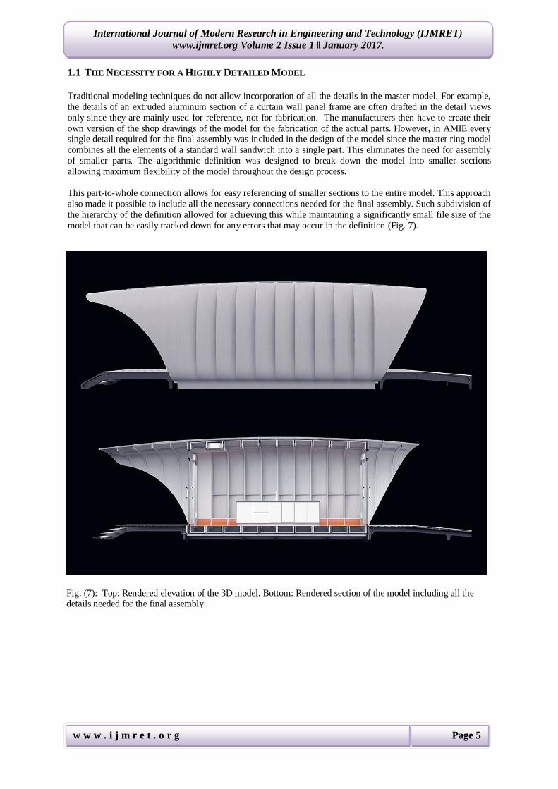
This part-to-whole connection allows for easy referencing of smaller sections to the entire model. This approach
also made it possible to include all the necessary connections needed for the final assembly. Such subdivision of
the hierarchy of the definition allowed for achieving this while maintaining a significantly small file size of the
model that can be easily tracked down for any errors that may occur in the definition (Fig. 7).
Fig. (7): Top: Rendered elevation of the 3D model. Bottom: Rendered section of the model including all the details needed for the final assembly.

International Journal of Modern Research in Engineering and Technology (IJMRET) www.ijmret.org Volume 2 Issue 1 ǁ January 2017.
w w w . i j m r e t . o r g Page 6
1.2 A WATERTIGHT MODEL
One of the main goals of the research wasto use the final design to test the 3D-printing capabilities of the
BAAM. Therefore, the design team set up the model in such a way that ensured a constant check for naked and non-manifold edges. This also ensured that the model was “watertight” throughout every stage of the design
process and ready for immediate 3D-printing at any point (Fig. 8).
1.3 Non 3D Printed Parts Meet Maximum Flexibility of Model Alteration
Since the BAAM system allows for printing at high level of accuracy, the research team decided to utilize this
capability to incorporate all the detail of the hook ups, sockets, shrouds and sleeves, and to receive any non 3D
printed parts such as glazing, light fixtures, tension rod, doors, and the HVAC system.
Since at early stages of the design none of the final products were yet specified, the algorithmic definition was
designed to include a place holder for each known part with maximum flexibility to add any new elements as
required to the model throughout the design process. For instance, the structure team addressed the weakness of
the print in the Z direction by introducing a pre-tensioned rod that runs through the whole structure connecting
both ends. A special sleeve was added to the model at the four corners of each ring. Additionally, a custom pocket was added to each end of the canopies to host the rod disk spring. All brackets for ceiling light fixtures,
HVAC covers, doors and window frames were also dealt with in the same fashion (Fig. 9).
Fig. (8): Left: The model is constantly highlighting naked edges. Right: Same model after being repaired.
Fig. (9): Left: Detail of the pre-tensioned rod sleeve and light fixture socket; Right: 3D printed canopy with
incorporated rod sleeve and disk spring pocket.

International Journal of Modern Research in Engineering and Technology (IJMRET) www.ijmret.org Volume 2 Issue 1 ǁ January 2017.
w w w . i j m r e t . o r g Page 7
1.4 Rapid Model Adaptation for Major Design Changes
Initially, the design team chose to use reinforced fiberglass ABS for its durability during the initial tests and for
its natural white finish, eliminating the need to paint the final print. However, after the first full C ring was
printed, a major layer delamination problem occurred, and the research team started to question the structural
integrity of the material for that scale. More tests were done and it became apparent that ABS reinforced with
30% carbon fiber (black) is a better choice, resulting in much more durable printed sections and no layer
delamination occurrence when printed at full size scale.
This adjustment of the starting material also resulted in a change in the bead size due to changes in nozzle size
of the extruder from 0.30” to 0.35”. This required that every offset increment in the model had to match the
extruded thickness of the material from the 3D printer to prevent gaps and holes from appearing. While the
larger bead widths would eliminate the holes given coarser resolution settings, the team would have ended up with a gap between beads, limiting structural performance.
Overall, 16 different models with various offset increments (0.35, 0.36, 0.37 and 0.38) and different mesh
density/quality for each one (50%, 60% and 75%) were tested using tool path simulator software. A total of 48
models were tested to determine which increment translated the best and to find the balance between speed,
resolution and the quality of the final print (Fig. 10). It was also determined that a two-bead thickness for the
warped wall shell offered the best thickness to strength ratio. Increasing mesh quality to the finest level of mesh
resolution resulted in eliminating all the gaps in the prints, but it significantly increased the printing time. So the
team endeavored to find a balance between mesh quality and printing time.
Next, the team updated all the offset dimensions in the model based on the new tested increment. This mesh optimization resulted in reducing the printing time from 15 hours per C-section (half-ring) to 8 hours per section
(a 48% reduction in production time). The team also tested different mesh translators to best control mesh
density distribution. With traditional modeling techniques this task would be virtually impossible, requiring a
complete rebuild of the model every time one of these changes was made.
Fig. (10): Testing of the various bead sizes and mesh density using the tool path simulator.

International Journal of Modern Research in Engineering and Technology (IJMRET) www.ijmret.org Volume 2 Issue 1 ǁ January 2017.
w w w . i j m r e t . o r g Page 8
1.5 Interior Surface Optimization for MAI Panels
One of the key components that needed to be tested during the research project was a new type of vacuum-
insulated panel that is only 1 inch thick with the potential R-value of 35 hr-ft2-F/Btu. For comparison, current
building insulation materials can only achieve an R-value of 6 or less within 1 inch. The vacuum-insulated
panels have a very thin, fragile shell that, once punctured, loses almost 90% of its insulation value. These panels
have very limited flexibility in terms of bending beyond a certain angle, and a custom form has to be modeled to
create panels that are either warped or exceed a bending angle of 20 degrees. The team used a script that was
originally developed to optimize doubly-curved surfaces or undevelopable surfaces to reduce the number of hot
bent glass panels. The interior surface of the ring was optimized in the same way to reduce the number of
custom-bent panels while maximizing the number of standard flat panels (Fig. 11).
IV. Project Delivery
During the production of AMIE, an alternative process of building was demonstrated. Traditionally, architects
design a building and provide drawings to the contractor. The contactor then prepares shop drawings for
fabrication to be reviewed by the architect. The original design intent can be affected by multiple layers of
drawings, reviews and communication exchanges.
However, with AMIE the designers worked very closely with the researchers and the team responsible for the
final assembly of the parts. Rather than issuing the typical 2D representational drawings, the AMIE deliverable
was the actual 3D digital model shared directly with the printing team as an IGES data file (Fig. 12).
Fig. (11): Left: MAI incorporated in AMIE design. Right: MAI inserted into 3D printed rings during assembly.
Fig. (12): Construction document versus IGES data file.

International Journal of Modern Research in Engineering and Technology (IJMRET) www.ijmret.org Volume 2 Issue 1 ǁ January 2017.
w w w . i j m r e t . o r g Page 9
The data was processed and fed directly into BAAM. The built result was a physical manifestation of the actual
design model. Any errors in the 3D printed part could be immediately reported to the design team for revision
and alteration. Using this delivery method, problems were quickly reviewed and resolved with input from all
members of the team, greatly reducing the project timeline and eliminating chances for the design to get “lost in
translation”. This new delivery method using physibles on the other hand puts more responsibility on designers,
since it extends their role in the blurry lines between design and fabrication.
V. The Integrated Energy System
AMIE features the world’s first level 2 (6.6 kW) bi-directional wireless power transfer system. The transfer
system allows driver to charge the vehicle wirelessly when parked over the charging pad. The smart control
system is designed to decide which way the wireless power transfer should send energy and the origin of the energy (e.g., solar, wind, battery storage, the grid). This method offers a convenient and safer alternative to
plugging the electric vehicles into wall outlets.
VI. Conclusion and Future Work
AMIE (Fig. 14) is the world’s first and largest 3D printed polymer building that can share power with a vehicle.
This research was completed in a period of nine months, AMIE is an examination of new ways and technologies
to design and build energy efficient buildings that can also efficiently integrate with the grid and vehicles. In addition, AMIE’s design explores the potential for 3D printed systems of building components to combine all of
the wall elements such as structure, insulation, air and moisture barriers, and exterior cladding into one
vertically integrated building shell eliminating the need of assembly of smaller parts while significantly
reducing the wall thickness and achieving insulation value.
The design, engineering and science generated in AMIE also provide momentum for other examinations of how
large-scale additive manufacturing can be used in buildings. The high geometric control of additive
manufacturing paired with algorithmic modeling allows precise openings for fenestration, sockets, and other
details to be included in the model rather than being added later as separate elements, greatly reducing waste in
construction. With industry partners, the AMIE team will continue to investigate this and other opportunities to
leverage the success of AMIE to achieve energy efficient building technologies solutions.
Energy directed to storage array Grid connection option
Vehicle supplying energy to building Building supplying energy to vehicle.
Fig. (13): Building control and power management strategies directing electrical energy flow.

International Journal of Modern Research in Engineering and Technology (IJMRET) www.ijmret.org Volume 2 Issue 1 ǁ January 2017.
w w w . i j m r e t . o r g Page 10
Nomenclature
AMIE = Additive Manufacturing Integrated Energy
BAAM = Big Area Additive Manufacturing
MAI = Modified Atmosphere Insulation
References
[1.] Holshouser C., C. Newell, S. Palas, L. Love, V. Kune, R. Lind, P. Lloyd, J. Rowe, C. Blue, and C. Duty. 2013. Out of Bounds
Manufacturing. Advanced Materials and Processes 171(3):18-20.
[2.] Biswas K., Lind R., Post B., Jackson R., Love L., Tryggestad L., Obendorf A., Eikevik L. and Guerguis M. 2015. Big Area
Additive Manufacturing Applied To Buildings.
[3.] Liu Y., Pottmann H., Wallner J., Yang Y., and Wang W. 2006. Geometric modeling with conical meshes and developable
surfaces. ACM trans. Graphics.
[4.] Bentscheff I., Gengnagel C., Towards Teaching Generative Design in Architecture, Advances in Architectural Geometry 2010
[5.] Pottmann H., Asperl A., Hofer M., Kilian A., Bentley D., 2007. Architectural Geometry
[6.] Tedeschi A., 2011. Parametric Architecture with grasshopper. Le Penseur di Antonietta Andriuoli – Brienza - Italy
Fig. (14): Final assembledAMIE enclosure, pictured here at Oak Ridge National Laboratory, Knoxville, Tennessee.