Embed Size (px)
Citation preview

3000-0059
ESE00698-EN14 2012-10
Original manual
Instruction Manual
LKH Centrifugal Pump


Table of contents
The information herein is correct at the time of issue but may be subject to change without prior notice
1. EC Declaration of conformity .. . . . . . . . . . . . . . . . . . . . . . . . . . . . . . . . . . . . . . . . . . . . . . . . . . . . . . . . . . . . . . . . . . . . . . 4
2. Safety ... . . . . . . . . . . . . . . . . . . . . . . . . . . . . . . . . . . . . . . . . . . . . . . . . . . . . . . . . . . . . . . . . . . . . . . . . . . . . . . . . . . . . . . . . . . . . . . . . . 52.1. Important information .. . . . . . . . . . . . . . . . . . . . . . . . . . . . . . . . . . . . . . . . . . . . . . . . . . . . . . . . . . . . . . . . . . . . . . . . . . . . 52.2. Warning signs .. .. . . . . . . . . . . . . . . . . . . . . . . . . . . . . . . . . . . . . . . . . . . . . . . . . . . . . . . . . . . . . . . . . . . . . . . . . . . . . . . . . . 52.3. Safety precautions .. . .. . . . . . . . . . . . . . . . . . . . . . . . . . . . . . . . . . . . . . . . . . . . . . . . . . . . . . . . . . . . . . . . . . . . . . . . . . . . 6
3. Installation .. . . . . . . . . . . . . . . . . . . . . . . . . . . . . . . . . . . . . . . . . . . . . . . . . . . . . . . . . . . . . . . . . . . . . . . . . . . . . . . . . . . . . . . . . . . . . 73.1. Unpacking/Delivery . . .. . . . . . . . . . . . . . . . . . . . . . . . . . . . . . . . . . . . . . . . . . . . . . . . . . . . . . . . . . . . . . . . . . . . . . . . . . . . 73.2. Installation ... . . . . . . . . . . . . . . . . . . . . . . . . . . . . . . . . . . . . . . . . . . . . . . . . . . . . . . . . . . . . . . . . . . . . . . . . . . . . . . . . . . . . . . 93.3. Pre-use check - pump without impeller screw .. . . .. . . . . . . . . . . . . . . . . . . . . . . . . . . . . . . . . . . . . . . . . . . . 113.4. Pre-use check - pump with impeller screw .. .. . . . . . . . . . . . . . . . . . . . . . . . . . . . . . . . . . . . . . . . . . . . . . . . . 123.5. Recycling information .. . . . . . . . . . . . . . . . . . . . . . . . . . . . . . . . . . . . . . . . . . . . . . . . . . . . . . . . . . . . . . . . . . . . . . . . . . . . 13
4. Operation ... . . . . . . . . . . . . . . . . . . . . . . . . . . . . . . . . . . . . . . . . . . . . . . . . . . . . . . . . . . . . . . . . . . . . . . . . . . . . . . . . . . . . . . . . . . . . 144.1. Operation/Control . . . . . . . . . . . . . . . . . . . . . . . . . . . . . . . . . . . . . . . . . . . . . . . . . . . . . . . . . . . . . . . . . . . . . . . . . . . . . . . . . 144.2. Trouble shooting .. . . . . . . . . . . . . . . . . . . . . . . . . . . . . . . . . . . . . . . . . . . . . . . . . . . . . . . . . . . . . . . . . . . . . . . . . . . . . . . . . 164.3. Recommended cleaning ... . . . . . . . . . . . . . . . . . . . . . . . . . . . . . . . . . . . . . . . . . . . . . . . . . . . . . . . . . . . . . . . . . . . . . . 17
5. Maintenance .. . .. . . . . . . . . . . . . . . . . . . . . . . . . . . . . . . . . . . . . . . . . . . . . . . . . . . . . . . . . . . . . . . . . . . . . . . . . . . . . . . . . . . . . . . 185.1. General maintenance .. . . . . . . . . . . . . . . . . . . . . . . . . . . . . . . . . . . . . . . . . . . . . . . . . . . . . . . . . . . . . . . . . . . . . . . . . . . . 185.2. Cleaning Procedure .. .. . . . . . . . . . . . . . . . . . . . . . . . . . . . . . . . . . . . . . . . . . . . . . . . . . . . . . . . . . . . . . . . . . . . . . . . . . . . 205.3. Dismantling of pump/shaft seals . . . .. . . . . . . . . . . . . . . . . . . . . . . . . . . . . . . . . . . . . . . . . . . . . . . . . . . . . . . . . . . . 215.4. Assembly of pump/single shaft seal . . . . . . . . . . . . . . . . . . . . . . . . . . . . . . . . . . . . . . . . . . . . . . . . . . . . . . . . . . . . 245.5. Assembly of pump/flushed shaft seal . . . . . . . . . . . . . . . . . . . . . . . . . . . . . . . . . . . . . . . . . . . . . . . . . . . . . . . . . . . 275.6. Assembly of pump/double mechanical shaft seal .. . . . . . . . . . . . . . . . . . . . . . . . . . . . . . . . . . . . . . . . . . . . 305.7. Adjustment of shaft (LKH-5) . . .. . . . . . . . . . . . . . . . . . . . . . . . . . . . . . . . . . . . . . . . . . . . . . . . . . . . . . . . . . . . . . . . . . 335.8. Adjustment of shaft (LKH-10 to -90) . . . . . . . . . . . . . . . . . . . . . . . . . . . . . . . . . . . . . . . . . . . . . . . . . . . . . . . . . . . . 35
6. Technical data ... . . . . . . . . . . . . . . . . . . . . . . . . . . . . . . . . . . . . . . . . . . . . . . . . . . . . . . . . . . . . . . . . . . . . . . . . . . . . . . . . . . . . . . 376.1. Technical data .. .. . . . . . . . . . . . . . . . . . . . . . . . . . . . . . . . . . . . . . . . . . . . . . . . . . . . . . . . . . . . . . . . . . . . . . . . . . . . . . . . . . 376.2. Relubrication intervals . . . . . . . . . . . . . . . . . . . . . . . . . . . . . . . . . . . . . . . . . . . . . . . . . . . . . . . . . . . . . . . . . . . . . . . . . . . . 386.3. Torque Specifications .. . . . . . . . . . . . . . . . . . . . . . . . . . . . . . . . . . . . . . . . . . . . . . . . . . . . . . . . . . . . . . . . . . . . . . . . . . . . 416.4. Noise emission ... . . . . . . . . . . . . . . . . . . . . . . . . . . . . . . . . . . . . . . . . . . . . . . . . . . . . . . . . . . . . . . . . . . . . . . . . . . . . . . . . . 42
7. Parts list and service kits . . . . . . . . . . . . . . . . . . . . . . . . . . . . . . . . . . . . . . . . . . . . . . . . . . . . . . . . . . . . . . . . . . . . . . . . . . . . 437.1. LKH-5 Sanitary version .. . .. . . . . . . . . . . . . . . . . . . . . . . . . . . . . . . . . . . . . . . . . . . . . . . . . . . . . . . . . . . . . . . . . . . . . . . 437.2. LKH-10, -15, -20, -25, -35, -40, -50, -60, -70, -75, -85, -90 sanitary version ... . . . . . . . . . . 447.3. LKH - Product wetted parts . . . .. . . . . . . . . . . . . . . . . . . . . . . . . . . . . . . . . . . . . . . . . . . . . . . . . . . . . . . . . . . . . . . . . 467.4. LKH - Motor-dependent parts .. . . . . . . . . . . . . . . . . . . . . . . . . . . . . . . . . . . . . . . . . . . . . . . . . . . . . . . . . . . . . . . . . . 487.5. LKH - Shaft seal . . . . . . . . . . . . . . . . . . . . . . . . . . . . . . . . . . . . . . . . . . . . . . . . . . . . . . . . . . . . . . . . . . . . . . . . . . . . . . . . . . 50
3

1 EC Declaration of conformity
The designated company
Alfa LavalCompany Name
Albuen 31, DK-6000 Kolding, DenmarkAddress
+45 79 32 22 00Phone No.
hereby declare that
Pump LKH 2009-12-29Denomination Type Year
is in conformity with the following directives with amendments:- Low Voltage Directive 2006/95/EC
- EMC Directive 2004/108/EC- Machinery Directive 2006/42/EC
The technical construction file is retained at the above address
Manager, Product Center Fluid Handling Bjarne SøndergaardTitle Name
Alfa Laval KoldingCompany Signature
Designation
4

2 Safety
Unsafe practices and other important information are emphasised in this manual.Warnings are emphasised by means of special signs.Always read the manual before using the pump!
2.1 Important information
WARNINGIndicates that special procedures must be followed to avoid serious personal injury.
CAUTIONIndicates that special procedures must be followed to avoid damage to the pump.
NOTEIndicates important information to simplify or clarify procedures.
2.2 Warning signs
General warning:
Dangerous electrical voltage:
Caustic agents:
5

2 Safety
All warnings in the manual are summarised on this page.Pay special attention to the instructions below so that severe personal injury and/or damage to the pump are avoided.
2.3 Safety precautions
Installation:
Always read the technical data thoroughly. (See chapter 6 Technical data)Always use a lifting crane when handling the pump.
Pump without impeller screw:Always remove the impeller before checking the direction of rotation.Never start the pump if the impeller is fitted and the pump casing is removed.
Pump with Impeller screw:Never start in the wrong direction of rotation with liquid in the pump.Always have the pump electrically connected by authorised personnel. (See the motor instruction)
Operation:
Always read the technical data thoroughly. (See chapter 6 Technical data)Never touch the pump or the pipelines when pumping hot liquids or when sterilising.Never run the pump with both the suction side and the pressure side blocked.Never run the pump when partially installed or not completely assembled.Necessary precautions must be taken if leakage occurs as this can lead to hazardous situations.
Always handle lye and acid with great care.Never use the pump for products not mentioned in the Alfa Laval pump selection program.The Alfa Laval pump selection program can be acquired from your local Alfa Laval sales company.
Maintenance:
Always read the technical data thoroughly. (See chapter 6 Technical data)Never service the pump when it is hot.Never service the pump if pressurised.Always use Alfa Laval genuine spare parts.
Motors with grease nipples:Remember lubrication according to information plate/label on the motor.
Always disconnect the power supply when servicing the pump.
Transportation:Transportation of the pump or the pump unit:Never lift or elevate in any way other than described in this manualAlways drain the pump head and accessories of any liquidAlways ensure that no leakage of lubricants can occurAlways transport the pump in its upright positionAlways ensure that the unit is securely fixed during transportationAlways use the original packaging or similar during transportation
6

3 Installation
The LKH pump is a highly efficient and econominal centrifugal pump, which meets the requirements of sanitary and gentleproduct treatment and chemical resistsnce. LKH is available in the following sizes LKH-5, -10, -15, -20, -25, -35, -40, -50, -60,-70, -75, -85 and -90. The instruction manual is part of the delivery. Read the instructions carefully. The large pump sizes arevery heavy. Alfa Laval therefore recommends the use of a lifting crane when handling the pump.
3.1 Unpacking/Delivery
Step 1Always use a lifting crane when handling the pump (see technicaldata).
CAUTIONAlfa Laval cannot be held responsible for incorrect unpacking.
WARNING:Be aware that certain pump configurations can tilt, and thereforecause injuries to feet or fingers. The pump should be supportedunderneath the adaptor, when not installed in the process line.
Check the delivery for:1. Complete pump.2. Delivery note.3. Motor instructions.
Step 2Remove any packing materials from the inlet and the outlet.Avoid damaging the inlet and the outlet.Avoid damaging the connections for flushing liquid, if supplied.
3000-0060
Removepacking
materials!
SStep 3Inspect the pump for visible transport damage.
Inspection!
3000-0060
SStep 4Always remove the shroud, if fitted, before lifting the pump.
Remove the shroud before lifting!
3000-0061
7
3 Installation
The LKH pump is a highly efficient and econominal centrifugal pump, which meets the requirements of sanitary and gentleproduct treatment and chemical resistsnce. LKH is available in the following sizes LKH-5, -10, -15, -20, -25, -35, -40, -50, -60,-70, -75, -85 and -90. The instruction manual is part of the delivery. Read the instructions carefully. The large pump sizes arevery heavy. Alfa Laval therefore recommends the use of a lifting crane when handling the pump.
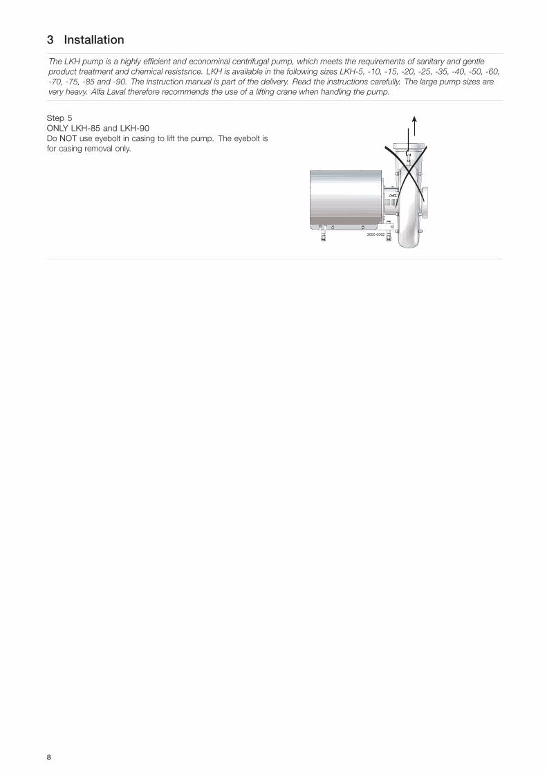
Step 5ONLY LKH-85 and LKH-90Do NNOT use eyebolt in casing to lift the pump. The eyebolt isfor casing removal only.
3000-0062
8
3 Installation
Read the instructions carefully and pay special attention to the warnings! Always check the pump before operation.- See pre-use check in section 3.3 Pre-use check - pump without impeller screw.The large pump sizes are very heavy.Alfa Laval therefore recommends the use of a lifting crane when handling the pump.
3.2 Installation
Step 1
Always read the technical data thoroughly.(See chaper 6 Technical data)
Always use a lifting crane when handling the pump.
Always have the pump electrically connected by authorisedpersonnel. (See the motor instructions).
CAUTIONAlfa Laval cannot be held responsible for incorrect installation.
WARNING:Alfa Laval recommends the installation of a lockable repairbreaker. If the repair breaker is to be used as an emergency stop,the colors of the repair breaker must be red and yellow.
Caution:The pump does not prevent back flow whenintentionally or unintentionally stopped. If back flowcan cause any hazardous situations, precautionsmust be taken e.g. check the valve to be installedin the system preventing hazardous situations fromarising.
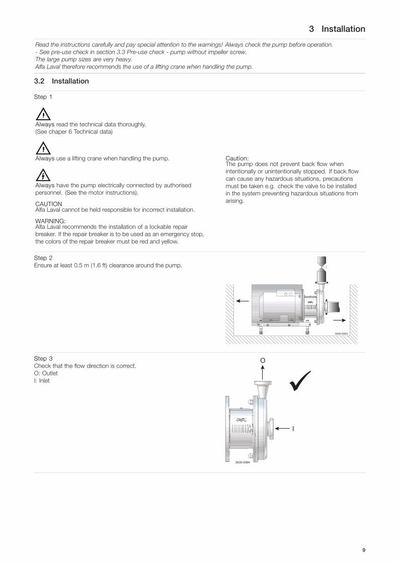
Step 2Ensure at least 0.5 m (1.6 ft) clearance around the pump.
3000-0063
SStep 3Check that the flow direction is correct.O: OutletI: Inlet
3000-0064
O
I
�
9

3 Installation
Read the instructions carefully and pay special attention to the warnings! Always check the pump before operation.- See pre-use check in section 3.3 Pre-use check - pump without impeller screw.The large pump sizes are very heavy.Alfa Laval therefore recommends the use of a lifting crane when handling the pump.
Step 41. Ensure that the pipelines are routed correctly.2. Ensure that the connections are tight.
Remember seal rings
3000-0065 Few bendsCorrect
SStep 5Avoid stress on the pump.Pay special attention to:- Vibrations.- Thermal expansion of the tubes.- Excessive welding.- Overloading of the pipelines.
3000-0066
!
NNoteIn case of shaft seal leakage, the media will drip from the slot in the bottom of the adaptor. In case of shaft seal leakage, AlfaLaval recommends putting a drip tray underneath the slot to collect the leakage.
10

3 Installation
Read the instructions carefully and pay special attention to the warnings!LKH-5 to -60 comes without impeller screw as standard but can be supplied with one.Check the direction of rotation of the impeller before operation.- See the indication label on the pump.
3.3 Pre-use check - pump without impeller screw
Step 1
Always remove the impeller before checking the direction ofrotation.
Never start the pump if the impeller is fitted and the pump casingis removed.1.
A. LKH-5: Remove screws (56), spring washers (56a), clamps(55+55a) and pump casing (29).
B. LKH-10 to -60: Remove cap nuts (24), washers (24a) andpump casing (29).
2. Remove impeller (27) (see also instruction in section 5.4Assembly of pump/single shaft seal).
3000-0067
SStep 21. Start and stop the motor momentarily.2. Ensure that the direction of rotation of the stub shaft (7) is
anticlockwise as viewed from the inlet side.
3000-0068
�
Stub shaft
SStep 3Fit and tighten impeller (27).
3000-0069
SStep 41. Fit pump casing (29).2.
A. LKH-5: Fit clamps (55+55a), spring washers (56a) andtighten screws (56)
B. LKH-10 to -60: Fit washers (24a) and tighten cap nuts (24),according to torque values in chapter 6 Technical data
3000-0070
11

3 Installation
Read the instructions carefully and pay special attention to the warnings!LKH-5 to -60 comes without impeller screw as standard but can be supplied with one.Check the direction of rotation of the impeller before operation.- See the indication label on the pump.
3.4 Pre-use check - pump with impeller screw
Never start in the wrong direction of rotation with liquid inthe pump.
1. Start and stop the motor momentarily.2. Ensure that the direction of rotation of the motor fan is
clockwise as viewed from the rear end of the motor.
3000-0071
�
View from rear end ofmotor
12

3 Installation
Read the instructions carefully and pay special attention to the warnings!LKH-5 to -60 comes without impeller screw as standard but can be supplied with one.Check the direction of rotation of the impeller before operation.- See the indication label on the pump.
3.5 Recycling information
Unpacking- Packing material consists of wood, plastics, cardboard boxes and in some cases metal straps- Wood and cardboard boxes can be re-used, recycled or used for energy recovery- Plastics should be recycled or burnt at a licensed waste incineration plant- Metal straps should be sent for material recycling
Maintenance- During maintenance, oil and wearing parts in the machine are replaced- All metal parts should be sent for material recycling- Worn out or defective electronic parts should be sent to a licensed handler for material recycling- Oil and all non-metal wearing parts must be disposed of in accordance with local regulations
Scrapping- At the end of use, the equipment must be recycled according to relevant local regulations. Besides the equipment itself, any
hazardous residues from the process liquid must be taken into consideration and dealt with in a proper manner. When indoubt, or in the absence of local regulations, please contact your local Alfa Laval sales company.
13
4 Operation
Read the instructions carefully and pay special attention to the warnings!
4.1 Operation/Control
Step 1
Always read the technical data thoroughly. See chapter 6 Technical data
CAUTIONAlfa Laval cannot be held responsible for incorrect operation/control.
Step 2
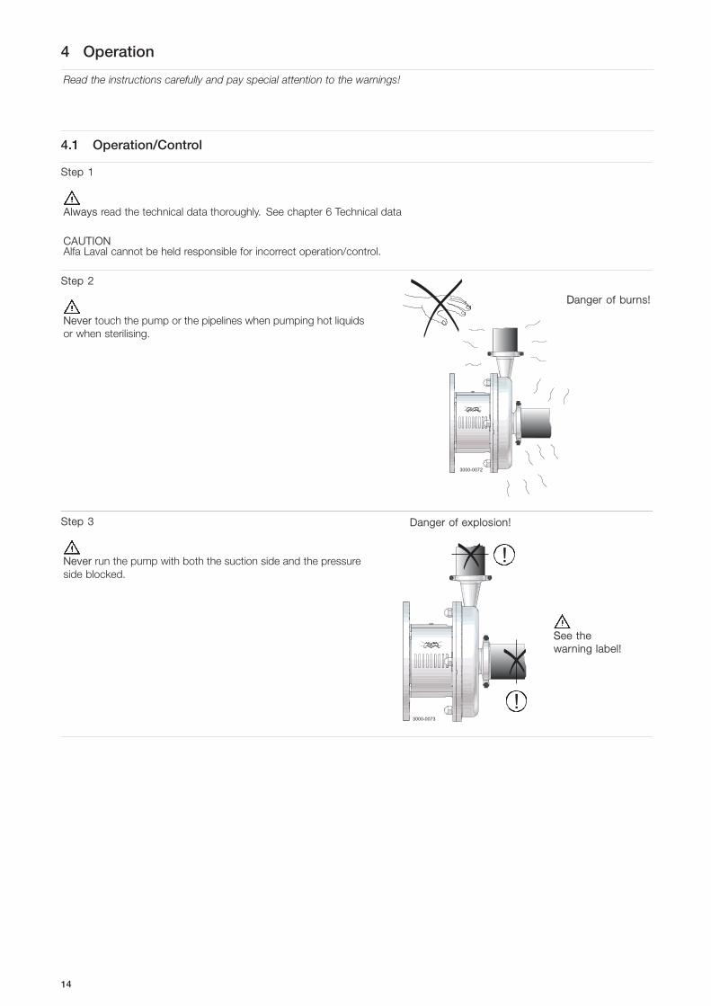
Never touch the pump or the pipelines when pumping hot liquidsor when sterilising.
3000-0072
DDanger of burns!
Step 3
Never run the pump with both the suction side and the pressureside blocked.
Danger of explosion!
3000-0073
!
!
SSee thewarning label!
14

4 Operation
Read the instructions carefully and pay special attention to the warnings!
Step 4
CAUTIONThe shaft seal must not run dry.
CAUTIONNever throttle the inlet side.
Do not allow torun dry
3000-0074
�
�
SStep 5
Double mechanical/flushed shaft seal:1. Connect the inlet of the flushing liquid correctly. (R1/8”
BSP).2. Regulate the water supply correctly.
For LKH-85: connect inlet/outlet of the flushing liquid directly onthe flushing housing. (ø6 tube).
O: OutletI: Inlet
3000-0075_1
�O
I
Tmax = 70°CPmax = 1 bar (flush seal)
Pmax = 5 bar (doublemechanical seal)
SStep 6Control:Reduce the capacity and the power consumption by means of:
- Throttling the pressure side of the pump.- Reducing the impeller diameter.- Reducing the speed of the motor.
3000-0076
TThrottling!
15

4 Operation
Pay attention to possible faults.Read the instructions carefully.
4.2 Trouble shooting
NOTE!Read the maintenance instructions carefully before replacing worn parts.
Problem Cause/result Remedy
Motor overloaded - Pumping of viscous liquids - Larger motor or smaller impeller- Pumping of high density liquids- Low outlet pressure (counter pressure) - Higher counter pressure (throttling)- Lamination of precipitates from the
liquid- Frequent cleaning
Cavitation:- Damage - Low inlet pressure - Increase the inlet pressure- Pressure reduction (sometimes to
zero)- High liquid temperature - Reduce the liquid temperature
- Increase in the noise level - Reduce the pressure drop before thepump
- Reduce speed
Leaking shaft seal - Running dry Replace:All wearing parts
- Incorrect rubber grade If necessary:- Change rubber grade
- Abrasive particles in the liquid - Select stationary and rotating seal ringin silicon carbide/silicon carbide
Leaking O-ring seals Incorrect rubber grade Change rubber grade
16

4 Operation
The pump is designed for cleaning in place (CIP). CIP = Cleaning In Place.Study the instructions carefully and pay special attention to the warnings!NaOH = Caustic Soda.HNO3 = Nitric acid.
4.3 Recommended cleaning
Step 1
Always handle lye and acid with great care.
Caustic danger!
Always use rubber gloves! Always use protectivegoggles!
Step 2
Never touch the pump or the pipelines when sterilising.
3000-0072
DDanger of burns!
Step 3
Examples of cleaning agents: Use clean water, free from chlorides.
1. 1% by weight NaOH at 70°C (158°F).
1 kg (2.2 lb) + 100 l (26.4 gal) = Cleaning agent.NaOH water
2.2 l (0.6 gal) + 100 l (26.4 gal) = Cleaning agent.33%NaOH water
2. 0.5% by weight HNO3 at 70°C (158°F).
0.7 l (0.2 gal) + 100 l (26.4 gal) = Cleaning agent.53% HNO3 water
1. Avoid excessive concentrationof the cleaning agent
Dose gradually!2. Adjust the cleaning flow to the
process.Sterilisation of milk/viscousliquids
Increase the cleaning flow!
Step 4
Always rinse well with clean water after using a cleaning agent.
NOTECleaning agents must be stored/disposed of in accordance withcurrent regulations/directives.
Always rinse!
Clean water Cleaning agent
17

5 Maintenance
Maintain the pump with care. Read the instructions carefully and pay special attention to the warnings!Always keep spare shaft seals and rubber seals in stock.See separate motor instructions.Check the pump for smooth operation after service.
5.1 General maintenance
Step 1
Always read the technical data thoroughly. (See chaper 6 Technical data)
Always disconnect the power supply when servicing the pump.
NOTEAll scrap must be stored//disposed of in accordance with current rules/directives.
Step 2
Never service the pump when it is hot.
3000-0072
DDanger of burns!
Step 3
Never service the pump with pump if pressurised.
CAUTIONFit the electrical connections correctly if they have been removedfrom the motor during service.
CAUTIONPay special attention to the warnings!
3000-0077
Atmospheric pressurerequired!
SStep 4Recommended spare parts:Order service kits from the service kits list(See chapter 7 Parts list and service kits).
Ordering spare partsContact your local Alfa Laval sales company.
Note:If the pump is supplied with FEP O-rings, Alfa Laval recommends that the casing O-ring is replaced during pump maintenance.
18

5 Maintenance
Maintain the pump with care. Read the instructions carefully and pay special attention to the warnings!Always keep spare shaft seals and rubber seals in stock.See separate motor instructions.Check the pump for smooth operation after service.
Shaft seal Rubber seals Motor bearings
Preventive maintenance RReplace after 12 months:(one-shift) Complete shaft seal
Replace when replacing theshaft seal
Maintenance after leakage(leakage normally starts slowly)
Replace at the end of theday: Complete shaft seal
Replace when replacing theshaft seal
Planned maintenance - Regular inspection forleakage and smoothoperation
- Keep a record of the pump- Use the statistics for
inspection planning
Replace after leakage:Complete shaft seal
Replace when replacing theshaft seal
Yearly inspection isrecommended- Replace complete bearing
if worn- Ensure that the bearing is
axially locked (See motorinstructions)
Lubrication BBefore fittingLubricate the O-rings withsilicone grease or silicone oil
Before fittingSilicone grease or silicone oil
See section 6.2 Relubricationintervals
Pre-use check
CAUTION!Fit the electrical connections correctly if they have been removed from the motor during servicing.(See pre-use check in section 3 Installation).
Pay special attention to warnings!
1. Start and stop the motor momentarily2. Ensure that the pump operates smoothly.
19

5 Maintenance
5.2 Cleaning Procedure
Cleaning procedure for soiled impeller screw tapped hole:
1. Remove stub shaft (7) as per section 4 of the Service manual.2. Submerge and soak the stub shaft for 5 minutes in COP tank with 2% caustic wash3. Scrub the blind tapped impeller screw hole vigorously by plunging a clean 1/2” diameter sanitary bristle pipe brush in and out
of the hole for two minutes while submerged.4. Soak stub shaft (7) in acid sanitiser for 5 minutes, then scrub blind tapped hole as described in step 3 above.5. Rinse well with clean water and blow-dry blind tapped hole with clean air.6. Swab test the inside of the tapped hole to determine cleanliness.7. Should the swab test fail, repeat steps 2 to 6 above until the swab test is passed.
Should swab testing continue to fail, or time is of the essence, install a new (spare) stub shaft (7).
20

5 Maintenance
Read the instructions carefully. The items refer to the parts list and service kits section.Handle scrap correctly.
: Relates to the shaft seal.
5.3 Dismantling of pump/shaft seals
Step 11.
A. LKH-5: Remove screws (56), spring washers (56a), clamps(55+55a) and pump casing (29).
B. LKH-10 to 90: Unscrew cap nuts (24) and remove washers(24a) and pump casing (29).
3000-0078_1
LKH-85 and LKH-90
SStep 2Flushed / Double mechanical shaft seal:Unscrew tubes (42) using a spanner.
3000-0079
21

5 Maintenance
Read the instructions carefully. The items refer to the parts list and service kits section.Handle scrap correctly.
: Relates to the shaft seal.
Step 3Remove screw (23) and safety guard (22).
3000-0080
SStep 41. Remove impeller screw (36), if fitted.2. Remove impeller (27). If necessary, loosen the impeller by
knocking gently on the impeller vanes.3. Remove the O-ring (38) from the impeller, if fitted.
Counterhold with a screwdriver!
3000-0081
If necessary!
SStep 51. Pull off the O-ring (26) from back plate (25).2. Unscrew nuts (20) and remove washers (21) and the back plate.
3000-0082
SStep 61. Remove the stationary seal ring (11).2. Remove the O-ring (12) from back plate (25).
Use the toolsupplied
3000-0083 Left handthread!
SStep 7Flushed shaft seal:1. Remove screws (41) and seal housing (40).2. Pull out lip seal (43) from the seal housing.
3000-0084
22

5 Maintenance
Read the instructions carefully. The items refer to the parts list and service kits section.Handle scrap correctly.
: Relates to the shaft seal.
Step 8Double mechanical shaft seal:1. Remove screws (41) and seal housing (40a).2. Remove rotating seal rings (14) and drive ring (52) from spring
(13).3. Remove O-rings (15) from rotating seal rings (14).4. LKH-70 to 90: Remove cups (54) from rotating seal rings.
3000-0085
SStep 9Double mechanical shaft seal:1. Remove stationary seal ring (51) from seal housing (40a).2. Remove O-ring (50) from stationary seal ring (51).3. Remove O-ring (44) from seal housing (40a).
3000-0086
SStep 101. Remove the complete shaft seal from stub shaft (7).2. Remove spring (13) and rotating seal ring (14) from the drive
ring (10).
3000-0087
23

5 Maintenance
Read the instructions carefully. The items refer to the parts list and service kits section.Handle scrap correctly.
: Relates to the shaft seal.
5.4 Assembly of pump/single shaft seal
Step 11. Remove spring (13).
NOTE!Make sure that O-ring (15) has maximum clearance from thesealing surface. 3000-0088
Max
SStep 21. Refit spring (13) on rotating seal ring (14).2. Fit the spring and the rotating seal ring on drive ring (10).
CAUTIONEnsure that the driver on the drive ring enters the notch in therotating seal ring.
3000-0089
SStep 3Fit the complete shaft seal on stub shaft (7).
NOTE!Make sure that Connex pin (8) on the stub shaft enters the notchin drive ring (10).
3000-0090
SStep 41. Fit O-ring (12) on stationary seal ring (11) and lubricate.2. Screw the stationary seal ring into back plate (25).
CAUTIONOnly tighten by hand to avoid deforming the stationary seal ring.
(Max. 7 Nm/5 lbf-ft)Use the toolsupplied
3000-0091 Left handthread!
24

5 Maintenance
Read the instructions carefully. The items refer to the parts list and service kits section.Handle scrap correctly.
: Relates to the shaft seal.
Step 51. Clean the sealing surfaces with contact cleaner before fitting
back plate (25).2. Carefully guide the back plate onto adaptor (16).3. Fit washers (21) and nuts (20).
3000-0092
SStep 6Lubricate O-ring (26) and slide it onto back plate (25).
3000-0093
SStep 71. Lubricate O-ring (38) and fit it in impeller (37), if impeller screw
is used.2. Lubricate impeller hub with silicone grease or oil.3. Screw the impeller onto stub shaft (7).4. Fit impeller screw (39) and tighten, if used.Torque - 5-60 = 20 Nm (15 lbf-ft)Torque - 70-90 = 50 Nm (37 lbf-ft)
3000-0123
SStep 8Fit safety guards (22) and screw (23) and tighten.If pump is not supplied with flush connections, the holes in theadaptor will be covered by the guard.
3000-0094
25

5 Maintenance
Read the instructions carefully. The items refer to the parts list and service kits section.Handle scrap correctly.
: Relates to the shaft seal.
Step 91.
A. LKH-5: Fit pump casing (29), clamps (55+55a), spring washers (56a) and screws (56).B. LKH-10 to -90: Fit pump casing (29), washers (24a) and cap nuts (24).
2. Adjust pump casing to the right position.3.
A. LKH-5: Tighten nuts (20) for back plate (25) and tighten screws (56).B. LKH-10 to -90: Tighten nuts (20) for back plate (25) and tighten cap nuts (24), according to torque values in chapter 6
Technical data.
3000-0095_1
LKH-85 and LKH-90
26

5 Maintenance
Read the instructions carefully. The items refer to the parts list and service kits section.Lubricate the rubber seals before fitting them.
: Relates to the shaft seal.
5.5 Assembly of pump/flushed shaft seal
Step 1Flushed shaft seal:LKH-5 to -60 use ø63mm tubeLKH-70 to -90 press in lip seal by hand1. Fit lip seal (43) in seal housing (40).2. Lubricate O-ring (44) and slide onto the seal housing (40).3. Fit the seal housing on back plate (25) and tighten screws (41).
Use ø63 mm tube!
3000-0096
SStep 21. Lubricate O-ring (45) and fit it in drive ring (10).2. Fit spring (13) and rotating seal ring (14) on the drive ring.
CAUTIONEnsure that the driver on the drive ring enters the notch in therotating seal ring.
3000-0089
SStep 3Fit complete shaft seal on stub shaft (7) so that Connex pin (8) onthe stub shaft enters the notch in drive ring (10).
3000-0090
SStep 41. Carefully guide back plate (25) onto adaptor (16).2. Fit washers (21) and nuts (20).
3000-0092
27

5 Maintenance
Read the instructions carefully. The items refer to the parts list and service kits section.Lubricate the rubber seals before fitting them.
: Relates to the shaft seal.
Step 5Lubricate O-ring (26) and slide it onto back plate (25).
3000-0093
SStep 61. Lubricate O-ring (38) and fit it in impeller (37), if impeller screw
is used.2. Lubricate the impeller hub with silicone grease or oil.3. Screw impeller (27) onto stub shaft (7).4. Fit impeller screw (36) and tighten, if used.Torque - 5-60 20 Nm (15 lbf-ft)Torque - 70-90 50 Nm (37 lbf-ft)
3000-0069
SStep 71. Screw tubes (42) into seal housing (40).2. Tighten with a spanner.
3000-0097
SStep 8Fit safety guard (22) and screw (23) and tighten.
3000-0094
28

5 Maintenance
Read the instructions carefully. The items refer to the parts list and service kits section.Lubricate the rubber seals before fitting them.
: Relates to the shaft seal.
Step 91.
A. LKH-5: Fit pump casing (29), clamps (55+55a), spring washers (56a) and screws (56).B. LKH-10 to-90: Fit pump casing (29).
2. Tighten nuts (20) for back plate (25).3.
A. LKH-5: Tighten nuts (20) for back plate (25) and tighten screws (56).B. LKH-10 to -90: Fit washers (24a) and cap nuts (24) and tighten, according to the torque values in chapter 6 Technical data.
3000-0095_1
LKH-85 and LKH-90
29

5 Maintenance
Read the instructions carefully. The items refer to the parts list and service kits section.Lubricate the rubber seals before fitting them.
: Relates to the shaft seal.
5.6 Assembly of pump/double mechanical shaft seal
Step 1
1. Fit O-rings (15) in rotating seal rings (14).2. LKH-70 to -90: Fit cups (54) on rotating seal rings (14).3. Fit spring (13) on one of the rotating seal rings (14) and place the drive ring (52) in between.
Step 21. LKH-70 to -90: Turn the drive ring (52) in order to place it
correctly on the pump shaft (7).2. Fit the second rotating ring (14) on the other end of the spring.3. Place the parts on the stationary seal ring fitted in back plate
(25).
NOTEEnsure that both drive pins on the drive ring enter the notches inrotating seal rings.
Only LKH-70-90
3000-0098
TD239-007_1
SStep 31. Lubricate O-ring (44) and slide onto seal housing (40a).2. Lubricate O-ring (50) and fit on stationary seal ring (51) and fit
this in the seal housing.
3000-0099
SStep 41. Clean the sealing surfaces with contact cleaner.2. Fit seal housing (40a) on the back plate (25) and tighten screws
(41).
3000-0085
SStep 51. To enable fitting of back plate (25) with the shaft seal, remove
Connex pin (8) from stub shaft (7) (if fitted).2. Carefully guide the back plate onto adaptor (16).3. Fit washers (21) and nuts (20).
3000-0092
SStep 6Lubricate O-ring (26) and slide it onto back plate (25).
3000-0093
30
5 Maintenance
Read the instructions carefully. The items refer to the parts list and service kits section.Lubricate the rubber seals before fitting them.
: Relates to the shaft seal.
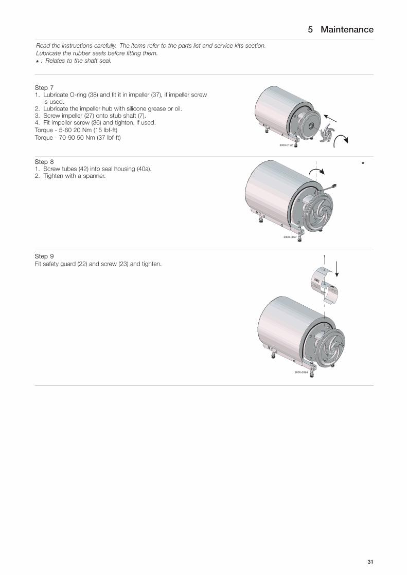
Step 71. Lubricate O-ring (38) and fit it in impeller (37), if impeller screw
is used.2. Lubricate the impeller hub with silicone grease or oil.3. Screw impeller (27) onto stub shaft (7).4. Fit impeller screw (36) and tighten, if used.Torque - 5-60 20 Nm (15 lbf-ft)Torque - 70-90 50 Nm (37 lbf-ft)
3000-0122
SStep 81. Screw tubes (42) into seal housing (40a).2. Tighten with a spanner.
3000-0097
SStep 9Fit safety guard (22) and screw (23) and tighten.
3000-0094
31

5 Maintenance
Read the instructions carefully. The items refer to the parts list and service kits section.Lubricate the rubber seals before fitting them.
: Relates to the shaft seal.
Step 101. Fit pump casing (29).2. Tighten nuts (20) for back plate (25).3.
A. LKH-5: Fit clamps (55+55a), spring washers (56a) and screws (56) and tighten.B. LKH-10 to -90: Fit washers (24a) and cap nuts (24) and tighten, according to torque values in chapter 6 Technical data.
3000-0095_1
LKH-85 and LKH-90
32

5 Maintenance
Read the instructions carefully. The items refer to the parts list and service kits section.Lubricate the rubber seals before fitting them.
: Relates to the shaft seal.
5.7 Adjustment of shaft (LKH-5)
Step 11. Loosen screws (6).2. Pull off stub shaft (7).
3000-0100
SStep 21. Push stub shaft (7) onto the motor shaft. Screws (4) must fit in
the keyway on the motor shaft.2. Check that the clearance between the end of the stub shaft
and the motor flange is 10-20 mm (0.39 - 0.78 inch).
3000-0101
10-20 mm(0.39-0.78 inch)
SStep 31. Tighten screws (4) lightly and evenly.2. Ensure that stub shaft (7) can be moved on the motor shaft.
3000-0102
SStep 41. FFor the double mechanical shaft seal: Fit drive ring (52) on
stub shaft (7).2. Fit back plate (25), washers (21) and nuts (20) and tighten.
3000-0103
33

5 Maintenance
Read the instructions carefully. The items refer to the parts list and service kits section.Lubricate the rubber seals before fitting them.
: Relates to the shaft seal.
Step 51. Fit impeller (27) on stub shaft (7).2. Ensure that the clearance between the impeller and back plate
(25) is correct: 0.5 mm (0.02 inch) for LKH-5.
3000-0104
LKH-5 = 0.5 mm(0.02 inch)
SStep 6Tighten screws (4) evenly to 18 Nm (13 lbf-ft).
3000-0105
34
5 Maintenance
Read the instructions carefully. The items refer to the parts list and service kits section.Lubricate the rubber seals before fitting them.
: Relates to the shaft seal.
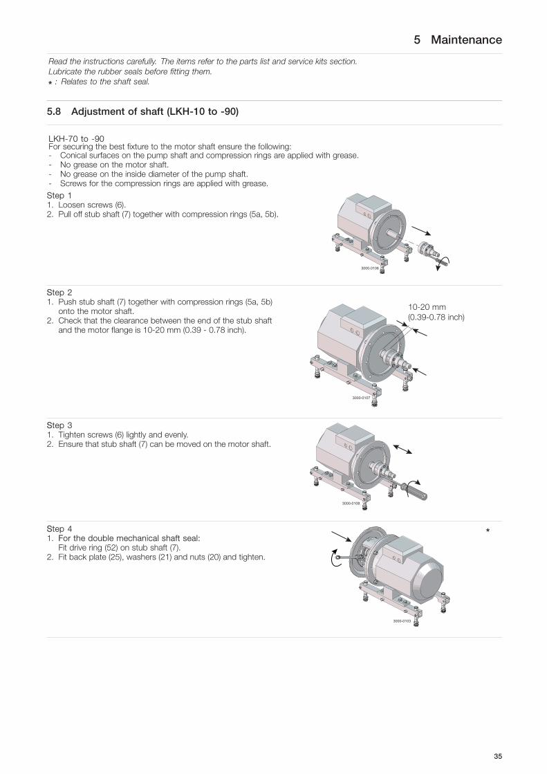
5.8 Adjustment of shaft (LKH-10 to -90)
LKH-70 to -90For securing the best fixture to the motor shaft ensure the following:- Conical surfaces on the pump shaft and compression rings are applied with grease.- No grease on the motor shaft.- No grease on the inside diameter of the pump shaft.- Screws for the compression rings are applied with grease.Step 11. Loosen screws (6).2. Pull off stub shaft (7) together with compression rings (5a, 5b).
3000-0106
SStep 21. Push stub shaft (7) together with compression rings (5a, 5b)
onto the motor shaft.2. Check that the clearance between the end of the stub shaft
and the motor flange is 10-20 mm (0.39 - 0.78 inch).
3000-0107
10-20 mm(0.39-0.78 inch)
SStep 31. Tighten screws (6) lightly and evenly.2. Ensure that stub shaft (7) can be moved on the motor shaft.
3000-0108
SStep 41. FFor the double mechanical shaft seal:
Fit drive ring (52) on stub shaft (7).2. Fit back plate (25), washers (21) and nuts (20) and tighten.
3000-0103
35

5 Maintenance
Read the instructions carefully. The items refer to the parts list and service kits section.Lubricate the rubber seals before fitting them.
: Relates to the shaft seal.
Step 51. Fit impeller (27) on stub shaft (7).2. Ensure that the clearance between the impeller and back plate
(25) is correct: 0.5 mm (0.02 inch) for LKH-10 to 60 and 1.0mm (0.039 inch) for LKH-70 to -90.
3. Tighten screws (6) evenly until the stub shaft (7) cannot moveon the motor shaft.
LKH-10 to -60 = 0.5 mm (0.02 inch)LKH-70 to -90 = 1.0 mm (0.039 inch)
3000-0104
SStep 61. Remove impeller (27), back plate (25) and drive ring (52).2. Tighten screws (6) evenly to 15 Nm (11 lbf-ft).
Counterhold with a screwdriver
15Nm(11 lbf-ft)
3000-0109
36

6 Technical data
It is important to observe the technical data during installation, operation and maintenance.Inform personnel about the technical data.
6.1 Technical data
Data
Max. inlet pressure LKH-5 : 600 kPa (6 bar) (87 psi )LKH-10 to -70 (50 Hz): 1000 kPa (10 bar) (145 psi )LKH-85 and LKH-90 (50 Hz): 500 kPa (5 bar) (72.5 psi)LKH-10 to -60 (60 Hz): 1000 kPa (10 bar) (145 psi )LKH-70, LKH-75, LKH-85, LKH-90 (60 Hz): 500 kPa (5 bar) (72.5 psi )
Temperature range -10oC to +140oC (EPDM) (14 to 284oF )Max. speed: 4000 rpm
Materials
Product wetted steel parts AISI 316LOther steel parts AISI 304Finish Semi-brightProduct wetted seals EPDM (standard)Other O-rings EPDM (standard)Alternative seals Nitrile (NBR), fluorinated rubber (FPM) and FEP
Shaft seal
Seal types External single, flushed or double mechanical sealMax. temperature flush media 70oCMax. water pressure (flushed seal) Normally atmospheric (max. 1 bar) (max. 14.5 psi)Water consumption (flushed seal) 0.25 - 0.5 l/min. (0.07-0.13 gl)Max. water pressure LKH-5 to -60 (DMS) Normally atmospheric (max. 5 bar) (max. 72.5 psi)Max. water pressure LKH-70 to -90 (DMS) Normally atmospheric (max. 3 bar) (max. 43.5 psi)Water consumption (double mechanical seal) 0.25-0.5 l/min. (0.07-0.13 gl )Material, stationary seal ring Acid-resistant steel with sealing surface of silicon carbideMaterial, rotating seal ring Carbon (standard) or silicon carbideMaterial, O-rings EPDM (standard)Alternative material, O-rings Nitrile (NBR), fluorinated rubber (FPM) and FEP
Motor
Foot-flanged motor according to IEC metric standard, 2 poles = 3000/3600 rpm. at 50/60 Hz IP55, insulation class F
Motor sizes (kW), 50 Hz 0.75 - 110 kWMotor sizes (kW), 60 Hz 0.9 - 110 kWMotor sizes (Hp), 60 Hz 1.5 - 150 Hp
For further information, see PD sheet.
37

6 Technical data
It is important to observe the technical data during installation, operation and maintenance.Inform personnel about the technical data.
6.2 Relubrication intervals
The table is for an internal bearing temperature of 100°C. An increase in temperature of 15°C (ambient or internal in bearings),will reduce the greasing interval and bearing lifetime by 50%. The lubrication interval for vertically mounted pumps is halfthe value stated in the table.
ABB IEC motors, IE2
Motorpower(kW)
LKH5 -90LKHI10 -60*
LKH-110*LKHSP
LKH UltraPure50/60 Hz
LKHPF-10 -70LKHI-10 -60
LKH-100LKH-12050/60 Hz
LKH-8550/60 Hz
0.75 Permanently lubricated Permanently lubricated1.1 Permanently lubricated Permanently lubricated1.5 Permanently lubricated Permanently lubricated2.2 Permanently lubricated Permanently lubricated3.0 Permanently lubricated Not available4.0 Permanently lubricated 4300h/3300h - DE/NDE:10g5.5 Permanently lubricated 3600h/3000h - DE/NDE:15g7.5 Permanently lubricated 3600h/3000h - DE/NDE:15g11 Permanently lubricated 3100h/2300h - DE/NDE:25g15 Permanently lubricated 3100h/2300h - DE/NDE:25g
18.5 Permanently lubricated 3100h/2300h - DE/NDE:25g22 Permanently lubricated 8000h/6000h - DE/NDE:42g30 Permanently lubricated 4500h/2000h - DE/NDE:55g 8000h/6000h - DE/NDE:40g37 Permanently lubricated 5000h/2500h - DE/NDE:55g 8000h/6000h - DE/NDE:40g45 Permanently lubricated 2500h/1000h - DE/NDE:55g 8000h/6000h - DE/NDE:40g55 Permanently lubricated 2500h/1000h - DE/NDE:73g 8000h/3000h - DE/NDE:60g75 Permanently lubricated 1500h/500h - DE/NDE:73g 4000h/1500h - DE/NDE:60g90 4000h/2800h - DE/NDE:45g
110 4000h/2800h - DE/NDE:45g* inlet pressure less than 10 bar (145 psi)
Recommended grease types:
LKHPF-10/-70 – LKH-110 - LKH-120:Esso: Unirex N2 or N3 (Lithium complex base)Mobil: Mobilith SHC 100 (Lithium complex base)Shell: Albida EMS 2 (Lithium complex base)Klüber: Klüberplex BEM 41-132 (Special lithium base)FAG: Arcanol TEMP110 (Lithium complex base)Lubcon: Turmogrease L 802 EP PLUS (Lithium complex base)
LKH-85:Klüber: Klüberplex Quiet BQH 72-102 (Polyurea base)Lubcon: Turmogrease PU703 (Polyurea base)
WARNING: Polyurea-based grease must not be mixed with Lithium complex base grease and vice versa.
38

6 Technical data
It is important to observe the technical data during installation, operation and maintenance.Inform personnel about the technical data.
WEG IEC Motors, IE3
Motor power(kW)
LKH-5 -70LKHI-10 -60*
LKH-110*LKHSP, LKH Evap
LKH UltraPure50/60 HZ
0.75 Permanently lubricated
1.1 Permanently lubricated
1.5 Permanently lubricated
2.2 Permanently lubricated
3.0 Permanently lubricated
4.0 Permanently lubricated
5.5 Permanently lubricated
7.5 Permanently lubricated
11 Permanently lubricated
15 Permanently lubricated
18.5 Permanently lubricated
22 10000/10000h - DE/NDE: 18g
30 10000/10000h - DE/NDE: 21g
37 10000/10000h - DE/NDE: 21g
45 Not available
55 5000/5000h - DE/NDE: 27g
75 5000/5000h - DE/NDE: 27g
* inlet pressure < 10 bar (145 psi)
Recommended grease types:
Mobil POLYREX EM 103
39

6 Technical data
It is important to observe the technical data during installation, operation and maintenance.Inform personnel about the technical data.
Table 1. Sterling Nema motors
Motor RPM Frame Type of serviceVS. HP Standard Heavy duty
8 hrs/day 24 hrs/day
143T - 286TS1.5 - 30
* *
3600324TS - 455TS
40 - 1506 Months 2 Months
143T - 256T1 - 20
* *
284T - 326T25 - 50
4 Months 18 Months1800
364T - 445T60 - 150
9 Months 3 Months
143T - 256T0.75 - 10
* *
284T - 326T15 - 30
4 Years 16 Years1200
364T - 445T40 - 125
1 Year 4 Months
* Motors of this size normally do not have bearings that can be re-lubricated.These bearings should be replaced at least every 5 years for 8 hr/day service, or every 2 years for 24 hr/day service.
Warning: Bearing grease must be Klüber NBU-15 - DO NOT SUBSTITUTE!
40

6 Technical data
It is important to observe the technical data during installation, operation and maintenance.Inform personnel about the technical data.
6.3 Torque Specifications
The table below specifies the tightening torques for the screws, bolts and nuts for this pump.Always use below torques if no other values are stated. This can be a matter of personal safety.
Size Tightening torqueNm lbf-ft
M8 20 14.8
M10 40 29.5
M12 67 49.0
M14 110 81.0
41

6 Technical data
It is important to observe the technical data during installation, operation and maintenance.Inform personnel about the technical data.
6.4 Noise emission
Pump Type Sound pressure level (dBA)
LKH-5 60
LKH-10 69
LKH-15 72
LKH-20 70
LKH-25 74
LKH-35 71
LKH-40 75
LKH-45 70
LKH-50 75
LKH-60 77
LKH-70 88
LKH-75 79
LKH-85 86
LKH-90 75
LKH-112 70
LKH-113 69
LKH-114 68
LKH-122 75
LKH-123 77
LKH-124 80
SolidC-1 68
SolidC-2 72
SolidC-3 73
SolidC-4 72
MR-166 76
MR-185 82
MR-200 81
MR-300 82
GM 54
FM-OS 61
The above LKH noise levels are the same for LKHPF, LKHI, LKH UltraPure, LKH Evap and LKHex.The above SolidC noise levels are the same for SolidC UltraPure.
The noise measurements have been carried out using the original motor and shroud, at the approximate Best EfficiencyPoint (BEP) with water at ambient temperature and at 50 Hz.
Very often, the noise level generated by the flow through the process system (e.g. valves, pipes, tanks etc.) is much higher thanwhat generated by the pump itself. Therefore, it is important to consider the noise level from the total system and take thenecessary precautions with regard to personal safety if required.
42

7 Parts list and service kits
The drawing shows LKH pump, sanitary version.
7.1 LKH-5 Sanitary version
3000-0110_2
US legs are different to the ones shown. For further information see US spare parts.
3000-0111_1 3000-0112_1 3000-0113_1
Impeller screw Ftting of legs0.75-1.1 kW
Fitting of back plate
3000-0114_1 3001-0058 3000-0115_1
Flushed shaft seal Single shaft seat Double mechanical shaft seal
43

7 Parts list and service kits
The drawing shows the LKH pump, sanitary version.
7.2 LKH-10, -15, -20, -25, -35, -40, -50, -60, -70, -75, -85, -90 sanitary version
3000-0117
LKH10 -75 LKH-85 and LKH-90
US legs are different to the ones shown. For further information see US spare parts.
3000-0112_1 3000-0113_1 3000-0120 TD 200-379_1
Only used for 0.75, 1.1and 3 kW
Fitting of legs
Fitting of back plate Only used for 55 - 110 kWFitting of legs
Impeller screw
3000-0114_1 3001-0058 3000-0121_1
**
Flushed shaft seal Single shaft seal Double mechanical shaft seal* Only used for LKH-70,
-75, -85, -90
44

.
45

7 Parts list and service kits
The drawing shows the LKH pump, sanitary version.
7.3 LKH - Product wetted parts
42
42a
1444
5150
40a
155215
DMSS
13
54 14LKH-70/-85/-90
42
42a
41
4242a
104443
40
FSS
1415134542
42a
41
16
17
21201415
1310
7
84
5b978
66a
5a
1918
46
35a
35
1
3
39
31
32
30a
33
3453
9614-0608_ROW
30b
55
56a
5625
55a
2738
111226
29a
28
36
57
29b26
2824
24a
29
37
25
24a24
28
2a
2
49
48
47
3000-0055
22
22
23
46

7 Parts list and service kits
The drawing shows the LKH pump, sanitary version.
Parts list
Pos. Qty Denomination
20 2 Nut21 2 Washer24 6 Cap nut24a 6 Washer25 1 Back plate26 1 O-ring
27 1 Impeller28 6 Bolt29 1 Pump casing36 1 Impeller screw37 1 Impeller for impeller screw38 1 O-ring55 1 Upper clamp55a 1 Lower clamp56 2 Screw56a 2 Spring washer57 1 Inducer
47

7 Parts list and service kits
The drawing shows the LKH pump, sanitary version.
7.4 LKH - Motor-dependent parts
42
42a
1444
5150
40a
155215
DMSS
13
54 14LKH-70/-85/-90
42
42a
41
4242a
104443
40
FSS
1415134542
42a
41
16
17
21201415
1310
7
84
5b978
66a
5a
1918
46
35a
35
1
3
39
31
32
30a
33
3453
9614-0608_ROW
30b
55
56a
5625
55a
2738
111226
29a
28
36
57
29b26
2824
24a
29
37
25
24a24
28
2a
2
49
48
47
3000-0055
22
22
23
48

7 Parts list and service kits
The drawing shows the LKH pump, sanitary version.
Parts list
Pos. Qty Denomination
1 1 Motor ABB1) (Full speed)2 1 Shroud3 4 Screw4 2 Screw5a 1 Compression ring with thread5b 1 Compression ring without thread6 6 Screw6a 6 Washer7 1 Shaft incl. pin8 1 Connex pin9 1 Retaining ring16 1 Adaptor17 4 Screw for adaptor18 4 Nut for adaptor19 4 Washer for adaptor22 1 Safety guard set23 1 Screw for safety guard30a 1 Support bar, right30b 1 Support bar, left31 4 Leg32 4 Screw33 4 Nut34 4 Spring washer35 4 Screw35a 4 Washer39 4 Nut46 4 Distance sleeve47 2 Leg bracket48 4 Nut for leg49 4 Screw for leg53 4 Pivot screw
49

7 Parts list and service kits
The drawing shows the LKH pump, sanitary version.
7.5 LKH - Shaft seal
42
42a
1444
5150
40a
155215
DMSS
13
54 14LKH-70/-85/-90
42
42a
41
4242a
104443
40
FSS
1415134542
42a
41
16
17
21201415
1310
7
84
5b978
66a
5a
1918
46
35a
35
1
3
39
31
32
30a
33
3453
9614-0608_ROW
30b
55
56a
5625
55a
2738
111226
29a
28
36
57
29b26
2824
24a
29
37
25
24a24
28
2a
2
49
48
47
3000-0055
22
22
23
50

7 Parts list and service kits
The drawing shows the LKH pump, sanitary version.
Parts list
Pos. Qty Denomination
Complete shaft sealComplete shaft sealComplete shaft sealComplete shaft sealComplete seal
10 1 Drive ring11 1 Stationary seal ring12 1 O-ring13 1 Spring14 1 Rotating seal ring15 1 O-ring40 1 Seal housing40a 1 Seal housing41 2 Screw for seal housing42 2 Tube42a 2 Fitting43 1 Lip seal44 1 O-ring for seal housing45 1 O-ring for drive ring50 1 O-ring51 1 Sec. stationary seal ring52 1 Drive ring54 2 Cup
Service kits
Denomination EPDM NBR FPM FEP
Service kit for single shaft seal C/SIC
Service kit, C/SIC (LKH-5) . . . . . . . . . . . . . . . . . . . . . . . . . . . . . . . . . . . . . 9611-92-2302 9611-92-2303 9611-92-2304 9611-92-2305
Service kit, C/SIC (LKH-10/15) . . . . . . . . . . . . . . . . . . . . . . . . . . . . . . . . 9611-92-2072 9611-92-2073 9611-92-2074 9611-92-2075
Service kit, C/SIC (LKH-20) . . . . . . . . . . . . . . . . . . . . . . . . . . . . . . . . . . . . 9611-92-2080 9611-92-2081 9611-92-2082 9611-92-2083
Service kit, C/SIC (LKH-25/35/45) . . . . . . . . . . . . . . . . . . . . . . . . . . . . . 9611-92-2178 9611-92-2179 9611-92-2180 9611-92-2181
Service kit, C/SIC (LKH-40/50/60) . . . . . . . . . . . . . . . . . . . . . . . . . . . . . 9611-92-2088 9611-92-2089 9611-92-2090 9611-92-2091
Service kit for single shaft seal SIC/SIC
Service kit, SIC/SIC (LKH-5) . . . . . . . . . . . . . . . . . . . . . . . . . . . . . . . . . . . 9611-92-2522 9611-92-2523 9611-92-2524 9611-92-2525
Service kit, SIC/SIC (LKH-10/15) . . . . . . . . . . . . . . . . . . . . . . . . . . . . . . 9611-92-2546 9611-92-2547 9611-92-2548 9611-92-2549
Service kit, SIC/SIC (LKH-20) . . . . . . . . . . . . . . . . . . . . . . . . . . . . . . . . . . 9611-92-2570 9611-92-2571 9611-92-2572 9611-92-2573
Service kit, SIC/SIC (LKH-25/35/45) . . . . . . . . . . . . . . . . . . . . . . . . . . . 9611-92-2594 9611-92-2595 9611-92-2596 9611-92-2597
Service kit, SIC/SIC (LKH-40/50/60) . . . . . . . . . . . . . . . . . . . . . . . . . . . 9611-92-2619 9611-92-2620 9611-92-2621 9611-92-2622
Service kit for single shaft seal and impeller screw C/SIC
Service kit, C/SIC (LKH-5) . . . . . . . . . . . . . . . . . . . . . . . . . . . . . . . . . . . . . 9611-92-2306 9611-92-2307 9611-92-2308 9611-92-2309
Service kit, C/SIC (LKH-10/15) . . . . . . . . . . . . . . . . . . . . . . . . . . . . . . . . 9611-92-2114 9611-92-2115 9611-92-2116 9611-92-2117
Service kit, C/SIC (LKH-20) . . . . . . . . . . . . . . . . . . . . . . . . . . . . . . . . . . . . 9611-92-2122 9611-92-2123 9611-92-2124 9611-92-2125
Service kit, C/SIC (LKH-25/35/45) . . . . . . . . . . . . . . . . . . . . . . . . . . . . . 9611-92-2182 9611-92-2183 9611-92-2184 9611-92-2185
Service kit, C/SIC (LKH-40/50/60) . . . . . . . . . . . . . . . . . . . . . . . . . . . . . 9611-92-2130 9611-92-2131 9611-92-2132 9611-92-2133
Service kit, C/SIC (LKH-70) . . . . . . . . . . . . . . . . . . . . . . . . . . . . . . . . . . . . 9611-92-2238 9611-92-2239 9611-92-2240 9611-92-2241
Service kit, C/SIC (LKH-85) . . . . . . . . . . . . . . . . . . . . . . . . . . . . . . . . . . . . 9611-92-2952 9611-92-2953 9611-92-2954 9611-92-2955
Service kit, C/SIC (LKH-90) . . . . . . . . . . . . . . . . . . . . . . . . . . . . . . . . . . . . 9611-92-2867 9611-92-2868 9611-92-2869 9611-92-2870
Service kit for single shaft seal and impeller screw SIC/SIC
Service kit, SIC/SIC (LKH-5) . . . . . . . . . . . . . . . . . . . . . . . . . . . . . . . . . . . 9611-92-2526 9611-92-2527 9611-92-2528 9611-92-2529
Service kit, SIC/SIC (LKH-10/15) . . . . . . . . . . . . . . . . . . . . . . . . . . . . . . 9611-92-2550 9611-92-2551 9611-92-2552 9611-92-2553
51

7 Parts list and service kits
The drawing shows the LKH pump, sanitary version.
Service kit, SIC/SIC (LKH-20) . . . . . . . . . . . . . . . . . . . . . . . . . . . . . . . . . . 9611-92-2574 9611-92-2575 9611-92-2576 9611-92-2577
Service kit, SIC/SIC (LKH-25/35/45) . . . . . . . . . . . . . . . . . . . . . . . . . . . 9611-92-2598 9611-92-2599 9611-92-2600 9611-92-2601
Service kit, SIC/SIC (LKH-40/50/60) . . . . . . . . . . . . . . . . . . . . . . . . . . . 9611-92-2623 9611-92-2624 9611-92-2625 9611-92-2626
Service kit, SIC/SIC (LKH-70) . . . . . . . . . . . . . . . . . . . . . . . . . . . . . . . . . . 9611-92-2643 9611-92-2644 9611-92-2645 9611-92-2646
Service kit, SIC/SIC (LKH-85) . . . . . . . . . . . . . . . . . . . . . . . . . . . . . . . . . . 9611-92-2964 9611-92-2965 9611-92-2966 9611-92-2967
Service kit, SIC/SIC (LKH-90) . . . . . . . . . . . . . . . . . . . . . . . . . . . . . . . . . . 9611-92-2879 9611-92-2880 9611-92-2881 9611-92-2882
Service kit for flushed shaft seal C/SIC
Service kit, C/SIC (LKH-5) . . . . . . . . . . . . . . . . . . . . . . . . . . . . . . . . . . . . . 9611-92-2310 9611-92-2311 9611-92-2312 9611-92-2313
Service kit, C/SIC (LKH-10/15) . . . . . . . . . . . . . . . . . . . . . . . . . . . . . . . . 9611-92-2076 9611-92-2077 9611-92-2078 9611-92-2079
Service kit, C/SIC (LKH-20) . . . . . . . . . . . . . . . . . . . . . . . . . . . . . . . . . . . . 9611-92-2084 9611-92-2085 9611-92-2086 9611-92-2087
Service kit, C/SIC (LKH-25/35/45) . . . . . . . . . . . . . . . . . . . . . . . . . . . . . 9611-92-2186 9611-92-2187 9611-92-2188 9611-92-2189
Service kit, C/SIC (LKH-40/50/60) . . . . . . . . . . . . . . . . . . . . . . . . . . . . . 9611-92-2092 9611-92-2093 9611-92-2094 9611-92-2095
Service kit for flushed shaft seal SIC/SIC
Service kit, SIC/SIC (LKH-5) . . . . . . . . . . . . . . . . . . . . . . . . . . . . . . . . . . . 9611-92-2530 9611-92-2531 9611-92-2532 9611-92-2533
Service kit, SIC/SIC (LKH-10/15) . . . . . . . . . . . . . . . . . . . . . . . . . . . . . . 9611-92-2554 9611-92-2555 9611-92-2556 9611-92-2557
Service kit, SIC/SIC (LKH-20) . . . . . . . . . . . . . . . . . . . . . . . . . . . . . . . . . . 9611-92-2578 9611-92-2579 9611-92-2580 9611-92-2581
Service kit, SIC/SIC (LKH-25/35/45) . . . . . . . . . . . . . . . . . . . . . . . . . . . 9611-92-2602 9611-92-2603 9611-92-2604 9611-92-2605
Service kit, SIC/SIC (LKH-40/50/60) . . . . . . . . . . . . . . . . . . . . . . . . . . . 9611-92-2627 9611-92-2628 9611-92-2629 9611-92-2630
Service kits
Denomination EPDM NBR FPM FEP
Service kit for flushed shaft seal and impeller screw C/SIC
Service kit, C/SIC (LKH-5) . . . . . . . . . . . . . . . . . . . . . . . . . . . . . . . . . . . . . 9611-92-2314 9611-92-2315 9611-92-2316 9611-92-2317
Service kit, C/SIC (LKH-10/15) . . . . . . . . . . . . . . . . . . . . . . . . . . . . . . . . 9611-92-2118 9611-92-2119 9611-92-2120 9611-92-2121
Service kit, C/SIC (LKH-20) . . . . . . . . . . . . . . . . . . . . . . . . . . . . . . . . . . . . 9611-92-2126 9611-92-2127 9611-92-2128 9611-92-2129
Service kit, C/SIC (LKH-25/35/45) . . . . . . . . . . . . . . . . . . . . . . . . . . . . . 9611-92-2190 9611-92-2191 9611-92-2192 9611-92-2193
Service kit, C/SIC (LKH-40/50/60) . . . . . . . . . . . . . . . . . . . . . . . . . . . . . 9611-92-2134 9611-92-2135 9611-92-2136 9611-92-2137
Service kit, C/SIC (LKH-70) . . . . . . . . . . . . . . . . . . . . . . . . . . . . . . . . . . . . 9611-92-2242 9611-92-2243 9611-92-2244 9611-92-2245
Service kit, C/SIC (LKH-85) . . . . . . . . . . . . . . . . . . . . . . . . . . . . . . . . . . . . 9611-92-2956 9611-92-2957 9611-92-2958 9611-92-2959
Service kit, C/SIC (LKH-90) . . . . . . . . . . . . . . . . . . . . . . . . . . . . . . . . . . . . 9611-92-2871 9611-92-2872 9611-92-2873 9611-92-2874
Service kit for flushed shaft seal and impeller screw SIC/SIC
Service kit, SIC/SIC (LKH-5) . . . . . . . . . . . . . . . . . . . . . . . . . . . . . . . . . . . 9611-92-2534 9611-92-2535 9611-92-2536 9611-92-2537
Service kit, SIC/SIC (LKH-10/15) . . . . . . . . . . . . . . . . . . . . . . . . . . . . . . 9611-92-2558 9611-92-2559 9611-92-2560 9611-92-2561
Service kit, SIC/SIC (LKH-20) . . . . . . . . . . . . . . . . . . . . . . . . . . . . . . . . . . 9611-92-2582 9611-92-2583 9611-92-2584 9611-92-2585
Service kit, SIC/SIC (LKH-25/35/45) . . . . . . . . . . . . . . . . . . . . . . . . . . . 9611-92-2606 9611-92-2607 9611-92-2608 9611-92-2609
Service kit, SIC/SIC (LKH-40/50/60) . . . . . . . . . . . . . . . . . . . . . . . . . . . 9611-92-2631 9611-92-2632 9611-92-2633 9611-92-2634
Service kit, SIC/SIC (LKH-70) . . . . . . . . . . . . . . . . . . . . . . . . . . . . . . . . . . 9611-92-2647 9611-92-2648 9611-92-2649 9611-92-2650
Service kit, SIC/SIC (LKH-85) . . . . . . . . . . . . . . . . . . . . . . . . . . . . . . . . . . 9611-92-2968 9611-92-2969 9611-92-2970 9611-92-2971
Service kit, SIC/SIC (LKH-90) . . . . . . . . . . . . . . . . . . . . . . . . . . . . . . . . . . 9611-92-2883 9611-92-2884 9611-92-2885 9611-92-2886
Service kit for double mechanical shaft seal C/SIC
Service kit, C/SIC (LKH-5) . . . . . . . . . . . . . . . . . . . . . . . . . . . . . . . . . . . . . 9611-92-2318 9611-92-2319 9611-92-2320 9611-92-2321
Service kit, C/SIC (LKH-10/15) . . . . . . . . . . . . . . . . . . . . . . . . . . . . . . . . 9611-92-2206 9611-92-2207 9611-92-2208 9611-92-2209
Service kit, C/SIC (LKH-20) . . . . . . . . . . . . . . . . . . . . . . . . . . . . . . . . . . . . 9611-92-2214 9611-92-2215 9611-92-2216 9611-92-2217
Service kit, C/SIC (LKH-25/35/45) . . . . . . . . . . . . . . . . . . . . . . . . . . . . . 9611-92-2222 9611-92-2223 9611-92-2224 9611-92-2225
Service kit, C/SIC (LKH-40/50/60) . . . . . . . . . . . . . . . . . . . . . . . . . . . . . 9611-92-2230 9611-92-2231 9611-92-2232 9611-92-2233
52

7 Parts list and service kits
The drawing shows the LKH pump, sanitary version.
Service kit for double mechanical shaft seal SIC/SIC
Service kit, SIC/SIC (LKH-5) . . . . . . . . . . . . . . . . . . . . . . . . . . . . . . . . . . . 9611-92-2538 9611-92-2539 9611-92-2540 9611-92-2541
Service kit, SIC/SIC (LKH-10/15) . . . . . . . . . . . . . . . . . . . . . . . . . . . . . . 9611-92-2562 9611-92-2563 9611-92-2564 9611-92-2565
Service kit, SIC/SIC (LKH-20) . . . . . . . . . . . . . . . . . . . . . . . . . . . . . . . . . . 9611-92-2586 9611-92-2587 9611-92-2588 9611-92-2589
Service kit, SIC/SIC (LKH-25/35/45) . . . . . . . . . . . . . . . . . . . . . . . . . . . 9611-92-2610 9611-92-2611 9611-92-2612 9611-92-2613
Service kit, SIC/SIC (LKH-40/50/60) . . . . . . . . . . . . . . . . . . . . . . . . . . . 9611-92-2635 9611-92-2636 9611-92-2637 9611-92-2638
Service kit for double mechanical shaft seal and impeller screw C/SIC
Service kit, C/SIC (LKH-5) . . . . . . . . . . . . . . . . . . . . . . . . . . . . . . . . . . . . . 9611-92-2322 9611-92-2323 9611-92-2324 9611-92-2325
Service kit, C/SIC (LKH-10/15) . . . . . . . . . . . . . . . . . . . . . . . . . . . . . . . . 9611-92-2210 9611-92-2211 9611-92-2212 9611-92-2213
Service kit, C/SIC (LKH-20) . . . . . . . . . . . . . . . . . . . . . . . . . . . . . . . . . . . . 9611-92-2218 9611-92-2219 9611-92-2220 9611-92-2221
Service kit, C/SIC (LKH-25/35/45) . . . . . . . . . . . . . . . . . . . . . . . . . . . . . 9611-92-2226 9611-92-2227 9611-92-2228 9611-92-2229
Service kit, C/SIC (LKH-40/50/60) . . . . . . . . . . . . . . . . . . . . . . . . . . . . . 9611-92-2234 9611-92-2235 9611-92-2236 9611-92-2237
Service kit, C/SIC (LKH-70) . . . . . . . . . . . . . . . . . . . . . . . . . . . . . . . . . . . . 9611-92-2416 9611-92-2417 9611-92-2418 9611-92-2419
Service kit, C/SIC (LKH-85) . . . . . . . . . . . . . . . . . . . . . . . . . . . . . . . . . . . . 9611-92-2960 9611-92-2961 9611-92-2962 9611-92-2963
Service kit, C/SIC (LKH-90) . . . . . . . . . . . . . . . . . . . . . . . . . . . . . . . . . . . . 9611-92-2875 9611-92-2876 9611-92-2877 9611-92-2878
Service kit for double mechanical shaft seal and impeller screw SIC/SIC
Service kit, SIC/SIC (LKH-5) . . . . . . . . . . . . . . . . . . . . . . . . . . . . . . . . . . . 9611-92-2542 9611-92-2543 9611-92-2544 9611-92-2545
Service kit, SIC/SIC (LKH-10/15) . . . . . . . . . . . . . . . . . . . . . . . . . . . . . . 9611-92-2566 9611-92-2567 9611-92-2568 9611-92-2569
Service kit, SIC/SIC (LKH-20) . . . . . . . . . . . . . . . . . . . . . . . . . . . . . . . . . . 9611-92-2590 9611-92-2591 9611-92-2592 9611-92-2593
Service kit, SIC/SIC (LKH-25/35/45) . . . . . . . . . . . . . . . . . . . . . . . . . . . 9611-92-2614 9611-92-2615 9611-92-2616 9611-92-2617
Service kit, SIC/SIC (LKH-40/50/60) . . . . . . . . . . . . . . . . . . . . . . . . . . . 9611-92-2639 9611-92-2640 9611-92-2641 9611-92-2642
Service kit, SIC/SIC (LKH-70) . . . . . . . . . . . . . . . . . . . . . . . . . . . . . . . . . . 9611-92-2651 9611-92-2652 9611-92-2653 9611-92-2654
Service kit, SIC/SIC (LKH-85) . . . . . . . . . . . . . . . . . . . . . . . . . . . . . . . . . . 9611-92-2972 9611-92-2973 9611-92-2974 9611-92-2975
Service kit, SIC/SIC (LKH-90) . . . . . . . . . . . . . . . . . . . . . . . . . . . . . . . . . . 9611-92-2887 9611-92-2888 9611-92-2889 9611-92-2890Parts marked with are included in the service kits. Recommended spare parts: Service kits. 900601/1Conversion kit - single to double mechanical shaft seal: Please order double mechanical service kit + pos. 40a+41+42 (for LKH-85 pos40a+41+42a). Conversion kit single to flushed shaft seal: Please order Flushed service kit + pos. 40+41+42 (for LKH85 pos. 40+41+42a).Replace to inducer (for pump with impeller screw). Please order pos. 7+57+38. Replace inducer (for pump without impellerscrew) pleaseorder pos. 7+57+37+38.
53

How to contact Alfa LavalContact details for all countries arecontinually updated on our website.Please visit www.alfalaval.com to access the information directly.
© 1999-02 Alfa Laval Corporate ABThis document and its contents is owned by Alfa Laval Corporate AB and protected by laws governing intellectual property and thereto related rights. It is the responsibility of the user of thisdocument to comply with all applicable intellectual property laws. Without limiting any rights related to this document, no part of this document may be copied, reproduced or transmitted in anyform or by any means (electronic, mechanical, photocopying, recording, or otherwise), or for any purpose, without the expressed permission of Alfa Laval Corporate AB. Alfa Laval Corporate ABwill enforce its rights related to this document to the fullest extent of the law, including the seeking of criminal prosecution.