Embed Size (px)
Citation preview

ALAXALA AX8600R
Quick Start Guide
AX86R-Q001-10X
Reading and storing this guide
- Before you use the equipment, carefully read the guide and make sure that you understand all safety precautions.
- After reading this guide, keep it in a convenient place for easy reference.

Relevant products
This manual applies to the models in the AX8600R series of devices.
Export restrictions
In the event that any or all ALAXALA products (including technologies, programs and services) described or contained herein
are controlled under any of applicable export control laws and regulations (including the Foreign Exchange and Foreign Trade
Law of Japan and United States export control laws and regulations), such products shall not be exported without obtaining
the required export licenses from the authorities concerned in accordance with the above laws.
Trademarks
Ethernet is a registered trademark of Xerox Corporation.
Other company and product names in this document are trademarks or registered trademarks of their respective owners.
Reading and storing this guide
Before you use the equipment, carefully read the guide and make sure that you understand all safety precautions.
After reading the guide, keep it in a convenient place for easy reference.
Notes
Information in this document is subject to change without notice.
Radio interference
This is a class A information technology device based on the standard of the Voluntary Control Council for Interference
(VCCI). In a domestic environment, this product may cause radio interference in which case the user may be required to take
corrective actions.
Editions history
August 2013 (Edition 1), AX86R-Q001-00X (obsolete)
February 2014 (Edition 2), AX86R-Q001-10X
Copyright
All Rights Reserved, Copyright (C) 2013,2014, ALAXALA Networks, Corp.
|
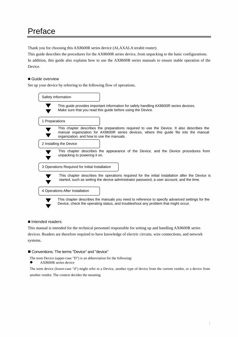
Preface
Thank you for choosing this AX8600R series device (ALAXALA terabit router).
This guide describes the procedures for the AX8600R series device, from unpacking to the basic configurations.
In addition, this guide also explains how to use the AX8600R series manuals to ensure stable operation of the
Device.
Guide overview
Set up your device by referring to the following flow of operations.
Intended readers
This manual is intended for the technical personnel responsible for setting up and handling AX8600R series
devices. Readers are therefore required to have knowledge of electric circuits, wire connections, and network
systems.
Conventions: The terms "Device" and "device"
The term Device (upper-case "D") is an abbreviation for the following: AX8600R series device
The term device (lower-case "d") might refer to a Device, another type of device from the current vendor, or a device from
another vendor. The context decides the meaning.
2 Installing the Device
3 Operations Required for Initial Installation
This chapter describes the appearance of the Device, and the Device procedures from unpacking to powering it on.
This chapter describes the operations required for the initial installation after the Device is started, such as setting the device administrator password, a user account, and the time.
Safety Information
This guide provides important information for safely handling AX8600R series devices. Make sure that you read this guide before using the Device.
4 Operations After Installation
This chapter describes the manuals you need to reference to specify advanced settings for the Device, check the operating status, and troubleshoot any problem that might occur.
1 Preparations
This chapter describes the preparations required to use the Device. It also describes the manual organization for AX8600R series devices, where this guide fits into the manual organization, and how to use the manuals.

||

Safety-1
The following indications are used as headings for the notes regarding safety. Phrases such as WARNING, CAUTION, and NOTICE are used in combination with the safety precaution symbol to indicate different levels of precautions.
This symbol is the safety precaution symbol. It is used to call attention to potential dangers to the user. Follow the instructions preceded by this indication to avoid possible death or injury. This indication is used to provide information on potential dangers that might cause death or serious injury. This indication is used to provide information on potential dangers that might cause minor to moderate injury This indication is used to provide information on dangers that might cause damage to the Device or nearby property.
This indication is used to provide supplementary information that, if ignored, will not result in physical injury or serious damage to the Device.
Indication example 1: Caution for electric shock
The graphic symbol of a triangle () indicates the need of caution, and the image in the symbol indicates the actual content of danger such electric shock.
Indication example 2: Disassembly prohibited
The graphic symbol of a circle with slash () indicates prohibition, and the image in the symbol indicates the prohibited action (for example, disassembly). This symbol indicates a general prohibition if there is no image inside it.
Indication example 3: Unplugging the power cable
The black circle symbol () indicates a mandatory instruction, and the image indicating the action (for example, unplugging the power cable) is inside the symbol. This symbol indicates general instructions if there is an exclamation mark ( ) inside it.
General notes about safety
Carefully read the following safety precautions and make sure that you fully understand them.
Keep this guide handy after reading it, so that it is available for later reference.
Operate the Device according to the instructions and procedures provided in this guide.
Heed all the warnings and cautions in this product and in the manuals.
Failure to do so might result in injury or damage to your property including this product.
Unauthorized operations Do not attempt to perform any operations that are not described in these manuals. If there is a problem with this product, turn off the power, unplug the power cable, and contact maintenance personnel.
Using common sense The warnings and cautions provided on this product and in the manuals have been selected after careful consideration. Nevertheless, there is always the possibility of the unexpected occurring. Therefore, while using the Device, stay alert and use common sense in addition to all following instructions.
Safety Information
WARNING
CAUTION
NOTICE
NOTE

Safety-2
If anything seems wrong, immediately turn off the power.
If smoke or an unusual smell is coming from the Device, or if liquid is spilled into the Device or a foreign object falls into the Device, immediately turn off power to the Device as described below. Continuing operation might result in a fire or electric shock.
If the Device has an AC power supply unit, turn off the Device, and then unplug the power cable.
If the Device has a DC power supply unit, turn off the Device, and then turn off the power facility circuit breaker. This is required for terminal connections.
Do not remove the Device cover.
Do not remove the Device cover. Doing so might result in electric shock.
Do not allow any foreign objects to get into the Device
Do not insert or drop any foreign objects, such as anything metallic or flammable, through the Device's ventilation slots. Doing so might result in a fire or electric shock.
Do not repair, modify, or disassemble the Device.
Do not repair, modify, or disassemble the Device. Doing so might result in electric shock, a fire, or burns. Touching anything inside the power unit is especially dangerous because the unit includes a large amount of high-voltage parts.
Do not subject the Device to shocks.
Do not subject the Device to excessive shocks, such as dropping it or hitting it with something. In the event that the Device is dropped or any of its components damaged, turn off the power, unplug the power cable, and contact maintenance personnel. Continuing operation might result in a fire or electric shock.
Do not place anything on the Device.
Do not place any metallic object such as a small pin or a paper clip or any container with a liquid, such as a vase or a flower pot, on the Device. Liquid or metallic objects falling into the Device might result in a fire or electric shock. Also, do not place any objects, including optional modules, on the Device. The optional module or similar part might fall off, resulting in injury. Also, the load of an object placed on the Device might result in a malfunction in the Device.
Use the Device only with the indicated power supply setting.
Do not use the Device at any voltage other than the indicated voltage. Inappropriate voltage might cause damage, overheating, and degradation inside the Device, resulting in a fire or electric shock. Use an outlet with the appropriate power voltage and socket shape. Using an inappropriate outlet might result in electric shock.
Safety Information (continued)
WARNING

Safety-3
Ensure that the capacity for incoming current to the distribution board is greater than
the operating current of the power facility circuit breaker.
Ensure that the capacity for incoming current to the distribution board is greater than the operating current of the power facility circuit breaker. If it is not, the power facility circuit breaker might not operate properly in the event of a failure, which might result in a fire.
Ground the Device.
When the Device is connected to a DC power supply unit, always connect the ground terminal for proper grounding. Failure to do so might not only result in electric shock, but it might also introduce unwanted electrical noise that might cause a Device failure.
Connecting and disconnecting a DC power cable must be performed by a trained
technician or maintenance personnel.
Connecting and disconnecting a DC power cable must be performed by a trained technician or maintenance personnel. Terminal connections are required for connection of the DC power cable. Incorrect handling of the DC power cable might result in a fire or electric shock.
Turn off the circuit breaker on the power facility before connecting or disconnecting the
DC power cable.
Turn off the circuit breaker on the power facility before connecting or disconnecting the DC power cable. If you perform an operation with the circuit breaker turned on, it might result in electric shock.
Place a terminal cover over the 0 V and −48 V terminals of DC power cables
When using a DC power cable, place a terminal cover over the 0 V and −48 V terminals. Using the terminals without a terminal cover might result in electric shock.
When using a DC power supply unit, do not use the terminal board with its cover removed.
When using a DC power supply unit, place a cover over the terminal board after connecting the power cable. Using the terminal board without a cover might result in electric shock.
Safety Information (continued)
WARNING

Safety-4
Installing and carrying the main unit must be performed by trained personnel or a
professional carrier.
The maximum weight of the main units is as shown in the table below. Installing and carrying the main unit must be performed by trained personnel or a professional carrier. If anyone other than those mentioned above performs these tasks, the main unit might fall, resulting in serious injury. Use a handling device such as a hand lifter when installing or carrying the main unit. Carrying the main unit without using a handling device might cause the main unit to fall, resulting in serious injury.
Maximum weight of the main units
Model Weight AX8616R 135kg AX8632R 220kg
Handle power cables carefully.
Use a designated power cable, and keep the notes below in mind while using it. Incorrect usage of the power cable might cause the copper wire to be exposed, a short circuit, or the wire to partially break, resulting in electric shock or a fire.
- Do not place any objects on the cable.
- Do not pull on the cable.
- Do not apply excessive pressure to the
cable.
- Do not bend the cable.
- Do not twist the cable.
- Do not modify the cable.
- Do not place the cable near a
heat-generating apparatus.
- Do not heat the cable.
- Do not bundle the cables.
- Do not fix the cable by using staples or in
any other similar manner.
- Do not use a damaged cable.
- Do not continuously expose the cable to ultraviolet
rays or strong visible rays of light.
- Do not expose the cable to alkali, acids, oils, or
humidity.
- Do not use the cable in a high-temperature
environment.
- Use the cable within the rated range.
- Do not use the cable for other devices.
- Hold the plug when unplugging the power cable.
- Do not touch the power plug with a wet hand.
Do not cover the power cable. If the power cable is covered by a carpet, it is easy to forget that the cable is there and to place something heavy on it.
Do not place anything near the outlet so that you can easily unplug the power cable when necessary.
Be aware of connection failures or arc tracking in the power plug.
Follow the instructions described below. If you do not follow these instructions, the power plug might cause overheating because of arc tracking or a connection failure, resulting in a fire.
Insert the power plug completely so that the prongs are not exposed.
Make sure that the power plug is free of dust or water drops before inserting it. If there is any dust or water on the plug, wipe it off before you insert the plug in the outlet.
Make sure that the outlet is not loose when you insert the power plug.
Construction on the outlet must be performed by a technician with the appropriate knowledge.
Safety Information (continued)
WARNING

Safety-5
Do not overload the power outlet.
Do not overload the power outlet by connecting multiple power plugs to the same outlet. Overloading the outlet causes the codes and outlet to overheat, and might result in a fire or in the power facility circuit breaker tripping due to excessive power used. This might affect other equipment.
To turn off the power, turn off all circuit breakers of the Device.
The Device has multiple input power supplies. To turn off the power, turn off all circuit breakers of the Device.
Adding or replacing a module must be performed by a trained technician or
maintenance personnel.
Adding or replacing optional modules must be performed by a trained technician or maintenance personnel. Replacing a power input unit requires the power cables to be connected and disconnected. If anyone other than those mentioned above performs these tasks incorrectly, a fire, electric shock, or a device failure might occur. In addition, using optional modules incorrectly might result in injury or a device failure.
When pressing the button of the basic control unit, do not use anything with a fragile
tip, or anything that might become caught in the Device, such as a pin or paper clip.
When pressing the button located behind the front panel of the basic control unit, do not use anything with a fragile tip, or anything that might become caught in the Device, such as a pin or paper clip. Doing so might result in a fire or electric shock.
Disconnect the power cable before replacing power input units.
When replacing a power input unit, disconnect the power cable from the power input unit to be replaced. If the power cable is connected and the circuit breaker on the power input unit is turned off, power is still supplied to some circuits. Because of this, if you replace a power input unit with the power cable connected, a fire or electric shock might occur. Make sure that you unplug the power cable from the power input unit to be replaced.
Do not use an air duster near a flame.
When cleaning the optical connectors, do not use an air duster that contains flammable gas near a flame. Doing so might result in a fire.
Storing the packaging bags
Keep the packaging bags for the Device away from children. If a child puts the packaging bag over his or her head, he or she might suffocate.
Safety Information (continued)
WARNING

Safety-6
Do not install the Device in a dusty or humid location.
Do not install the Device in a dusty or humid location. Doing so might result in a fire or electric shock.
If you move the Device to a location that has a significant temperature difference from
the previous location, do not use the Device immediately after you move it.
A significant difference in temperature might cause condensation on the surface or inside the Device. Using the Device while condensation is on the surface or inside the Device might result in a fire or electric shock. After moving the Device between two locations that have a significant temperature difference, let the Device stand a few hours before using it. Do not turn on the power immediately. Leave the Device for a few hours in the place where you will use it so that the temperature inside and outside the Device can equalize.
Do not stack Devices on top of one another.
Do not stack Devices on top of one another. Doing so might damage the Device. Furthermore, the
Device might fall or lose its balance, resulting in injury.
Do not step on the Device, lean against it, or place anything on it.
Do not step on the Device, lean against it, or place anything on it. Doing so might damage the Device.
Furthermore, the Device might fall or lose its balance, resulting in injury.
When mounting the Device in a rack, use guide rails.
The rack mounting brackets for the Device are for securing the main unit to the rack, not for
supporting the weight of the main unit. Use guide rails. Note that you need to use the guide rails that
are supplied with the rack and that can support the weight of the main unit (when all optional modules
are installed).
Do not block the ventilation slots.
The ventilation slots of the Device prevent temperature increases inside the Device. Do not block the
ventilation slots by placing anything on or against them. Doing so might cause the temperature inside
the Device to increase, resulting in smoke or a failure. Leave at least 100 mm around the ventilation
slots free from obstruction.
Periodically check and clean the ventilation slots so that the slots are always free of dust.
Do not allow hair or objects near the ventilation slots.
Cooling fan units are mounted in the Device. Do not allow anything near the ventilation slots. Doing
so causes heat to accumulate inside the Device and might cause a failure. Do not allow hair or other
objects near the ventilation slots. They might be sucked into the Device, resulting in injury.
CAUTION
Safety Information (continued)

Safety-7
When moving the Device, do not hold the handle of an optional module.
When moving the Device, do not hold the handle of the fan unit or power input unit, or the lever of the
power supply unit. The handle or lever might come off, resulting in the Device falling and possibly
causing injury. Additionally, the fan unit, power input unit, or power supply unit might become
damaged, resulting in a fire or electric shock.
When moving the Device, unplug all cables.
Before moving the Device, make sure that you turn it off and unplug all cables. Failure to do so might
cause the Device or cable to become damaged, resulting in a fire or electric shock.
Do not drop optional modules.
Handle the optional modules with care to avoid dropping them. Dropping them might cause injury.
The table below lists the weight of each optional module. When removing an optional module from the Device, hold the module tightly. Pulling it carelessly from a Device might cause it to fall, resulting in injury.
Weight of optional modules
Type Weight Power supply unit 6.1 kg Basic control unit 3.0 kg Packet routing unit (when a network interface board is mounted)
9.2 kg
Fan unit 1.7 kg
Do not touch the inside of the Device with your hands.
Do not carelessly put your hands inside the Device. The frame and components might cause injury.
Be careful of heat when removing a power supply unit.
The rear side of the power supply unit might be hot. Do not touch areas that are heated when you
replace the power supply unit. Doing so might result in burns.
Be careful of heat when removing a network interface board.
Some components mounted on a network interface board might be hot. Do not touch the mounted
components. Doing so might result in burns.
CAUTION
Safety Information (continued)

Safety-8
Do not touch the SFP-T transceiver during operation or just after operation has
stopped.
During operation and when a link is being established, the temperature of the SFP-T
transceiver can rise to 65oC. Do not touch the SFP-T transceiver while it is operating and just
after it has stopped. Doing so could result in burns.
When you remove the SFP-T transceiver, use the procedure below. Failure to do so could
result in burns. - To remove the SFP-T transceiver while the Switch is on, execute the inactive command,
and then wait 5 minutes before removing the SFP-T transceiver.
- To remove the SFP-T transceiver while the Switch is off, turn off the Switch, and then wait 5
minutes before removing the SFP-T transceiver.
Do not touch the Device directly if you have a metal allergy.
The Device is coated with zinc, nickel, gold, and other elements. Do not touch the Device directly if
you have an allergic reaction to these metals. Doing so might cause eczema or skin irritation.
Avoid looking directly at laser beams.
Laser devices such as the SFP or SFP+ modules and CFP module contain the parts to generate the laser
beams. Do not disassemble or modify the laser device. Also, do not look inside the laser device. You
might damage or lose your eyesight.
(Some laser beams are invisible.)
The following indications are for network interface boards that use laser beams.
Never use the Device or optional modules for purposes other than the intended use.
Use the Device and the optional module as a router only. Do not use them for other purposes such as a
step-ladder or bookends. The Device or optional module might break or fall over, resulting in injury or
damage to the Device or optional module.
CAUTION
Safety Information (continued)
CLASS 1 LASER PRODUCT
LASER RADIATIONDO NOT VIEW
WITH OPTICAL INSTRUMENTS CLASS 1M LASER PRODUCT
Caution: Hot (During operation, all sides are very hot.)

Safety-9
Lithium battery
The Device has a lithium battery for the real-time clock. Do not replace the lithium battery of the
Device. Keep the points below in mind. Incorrect handling of the lithium battery might cause heat
generation, rupture, or ignition, resulting in injury.
- Do not charge the battery.
- Do not short circuit the battery.
- Do not disassemble the battery.
- Do not heat the battery.
- Do not modify the battery.
- Do not throw the battery into the fire.
-Do not allow the battery to become wet.
Cleaning
Remove dust on and around the Device regularly. In addition to possibly causing the Device to stop,
accumulated dust might result in a fire or electric shock.
CAUTION
Safety Information (continued)

Safety-10
When the ACC LED is lit, do not remove the memory card or turn off the power.
When the ACC LED on the basic control unit is lit, the memory card is being accessed. When a
memory card is being accessed, do not remove the memory card or turn off the power. Doing so might
damage the memory card.
In addition, some commands require a certain amount of time after being entered to finish accessing
the card. Make sure that the memory card is no longer being accessed before removing the card or
turning off the power.
Handle memory cards carefully.
When inserting a memory card, do not push the card too strongly or flick it with your finger. When removing a memory card, do not forcibly pull out the card if it is locked. Doing so might damage the memory card slot connector.
When moving the main unit, remove any memory cards. If a memory card is subjected to excessive force when the Device is moved, the connector of the memory card slot might be damaged.
Do not attach any labels to a transceiver.
The transceivers have labels to certify that they are standard products of the manufacturer or
ALAXALA Networks Corporation. However, such labels are attached where they do not interfere with
heat dissipation from the transceiver or with the mechanism that prevents the transceiver from coming
loose from the cage.
Attaching a label to a location that interferes with these functions might cause a malfunction in the
transceiver or damage to the network interface boards.
Do not touch the connection terminals.
Do not touch the connecting terminals by hand or with metal, or insert objects such as a wire to short
circuit the terminal. Doing so might result in smoke or a connection failure.
Ensure that voltage drop does not occur in the power facility due to an inrush current.
Turning on the Device causes an inrush current. Ensure that voltage drop does not occur in the power
facility due to the inrush current. Voltage drops affect not only the Device, but also the devices
connected to the same power facility.
Turn off the circuit breaker on the power input unit before connecting or disconnecting
the power cable.
Before connecting or disconnecting a power cable, turn off the circuit breaker of the target power input
unit.
When carrying or packing the Device and an optional module, wear a wrist strap to
protect against static electricity.
Be sure to wear an antistatic wrist strap. If you handle the Device and an optional module without
wearing an antistatic wrist strap, you might damage them with static electricity.
NOTICE
Safety Information (continued)

Safety-11
When removing optional modules, attach blank panels.
Attach a blank panel to a slot where an optional module is not mounted. If you use the Device without
attaching a blank panel, airflow through the Device cannot be maintained. If airflow is not maintained,
the temperature inside the Device rises, resulting in failures. In addition, radio interference generated
by the Device might affect other devices, or radio interference generated by other devices might affect
the Device and cause a malfunction.
Before removing an optional module, loosen the screws completely.
The levers are used to remove basic control units, switch fabric units, packet routing units, or network
interface boards.
If the screws are not loosened completely, the optional module might be damaged when the levers are
opened.
Attach dust covers to the unused interface ports.
If dust covers are provided with the network interface board, use them to cover the unused interface
ports. Dust in the interface port might result in a failure.
Install the power input units to all the power input unit slots.
When using the Device, install the power input units to all the power input unit slots. If you use the
Device without connecting power input units, radio interference generated by the Device might affect
other devices, or radio interference generated by other devices might affect the Device and cause a
malfunction.
When carrying or packing an optional module, handle it carefully.
Do not touch the mounted components, the soldered surface, or the connection terminals when
carrying or packing an optional module such as fan unit, power input unit, power supply unit, basic
control unit, switch fabric unit, packet routing unit, network interface board, memory card, or
transceiver. Also, when storing a module, use an antistatic bag.
Handle the interface cables carefully.
Arrange the cables carefully so that no one will pull on or trip over the cables. Pulling on or tripping over the cables might result in injury or malfunction of the connected devices.
Do not place anything heavy on the cables. Also, do not place the cables near a heat-generating apparatus. The heat might damage the cable coating, resulting in a malfunction of the connected devices.
Check the Device usage environment.
Use the Device in an environment that satisfies the installation requirements. For example, if you place
the Device in direct sunlight or near a heater or other heat-generating device, the temperature inside the
Device will rise, resulting in a malfunction of the Device.
NOTICE
Safety Information (continued)

Safety-12
Keep the Device away from magnetism.
Keep the Device away from anything that generates magnetism such as magnets or audio speakers.
Keeping the Device near magnetism might result in a malfunction of the Device.
Do not use a TV or a radio near the Device.
Placing the Device near a TV or a radio might affect both devices. If you hear noise on the TV or radio,
do the following:
- Place the Device as far away as possible from the TV or radio.
- Adjust the orientation of the TV or radio antenna.
- Use separate outlets.
Do not place the Device where it will be exposed to hydrogen sulfide or salt.
Placing the Device in an area where sulfides are present, such as a hot-springs area, or in an area with
salty air, such as along a coast, might shorten the life of the Device.
Protect the Device when using liquids that generate mist.
Completely cover the Device with plastic bags or other protective materials when using liquids that
generate mist, such as pesticides. If liquids enter inside the Device, it might result in a failure.
In addition, turn off the Device beforehand.
Use care when handling an air duster.
Use an air duster specially designed for cleaning optical connectors. Using another type of air duster might cause the ferrule tip to become dirty.
Keep the nozzle or container of the air duster from coming into contact with the ferrule tip. Contact might result in a failure.
Use care when handling an optical connector cleaner.
Always use a dedicated optical connector cleaner. If you use another type of cleaner, the ferrule tip might become dirty.
Do not apply excessive pressure when cleaning. Doing so might damage the ferrule tip.
Transporting the Device
Always pack the Device thoroughly when transporting. Pay attention to the up and down direction of
the Device when packing it.
Failure to pack the Device or transporting the Device upside down might result in a malfunction of the
Device.
NOTICE
Safety Information (continued)

Safety-13
Maintenance
Clean any dirty areas on the exterior of the device with a clean, dry cloth, or a cloth damp with (but not soaked with) water or a neutral detergent. Do not use volatile organic solutions (such as benzene or paint thinner), chemicals, chemically treated cloths, or pesticides because these substances might deform, discolor, or damage the device.
If the Device will not be used for a long time
For safety reasons, unplug the power cable from the outlet if the Device will not be used for a long time.
Disposing of the Device
When disposing of the Device, you should either follow local ordinances or regulations, or contact your local waste disposal and treatment facility.
NOTICE
Safety Information (continued)

Safety-14
The warning labels that are attached to parts of the devices as shown in the figures below.
Read through the contents of the labels before handling the Device. Do not remove the labels or allow them to become soiled.
Warning Labels
Safety Information (continued)
The Device (rear side)

Safety-15
Warning Labels
Safety Information (continued)
Fan unit
Power supply unit
Packet routing unit
Basic control unit

Safety-16
Warning Labels
Safety Information (continued)
The bottom rear side of the power supply unit might be hot.
Power supply unit
SFP-T

i
Preface I
Safety Information Safety- 1
1 Preparations 1
1.1 Reading sequence of the AX8600R series manuals 2
1.2 Verifying supplied components 3
1.3 Preparing the necessary items 4
2 Installing the Device 5
2.1 Installing the Device 6
2.1.1 Overview of the installation steps 6
2.1.2 Details of the installation steps 10
2.2 Other preparations 13
3 Operations Required for Initial Installation 15
3.1 Overview of the command input modes 16
3.2 Overview of initial setup operations 17
3.3 Login 18
3.4 Setting the administrator mode password 19
3.5 Adding a user account and deleting the user account "operator" 20
3.6 Setting the time 21
4 Operations After Installation 23
4.1 Operation management and configuration settings 24
4.2 Troubleshooting 25
Contents

ii

1
1 Preparations
This chapter describes the preparations required to use the Device. It also describes the manual organization for AX8600R series devices, where this guide fits into the manual organization, and how to use the manuals.
1.1 Reading sequence for the AX8600R series manuals
1.2 Verifying supplied components
1.3 Preparing the necessary items

2
1.1 Reading sequence of the AX8600R series manuals
The figure below shows the reading sequence for the AX8600R series manuals.
This guide explains only the operations from unpacking the Device to setting it up for basic operation.
Note that this guide provides only a minimum amount of information. To take advantage of the wealth
of functions provided by AX8600R series devices, see the following manuals.
Reading sequence of the AX8600R series manuals
Figure1-1 Reading sequence of the AX8600R series manuals
Software Manual Operation Command Reference Vol. 3 (AX86R-S009X)
Software Manual Configuration Command Reference Vol. 3 (AX86R-S006X)
Software Manual Configuration Guide Vol. 3 (AX86R-S003X)
Unpacking the Device and understanding the basic settings for initial installation
AX8600R Quick Start Guide (AX86R-Q001X)
Determining the hardware setup requirements
Understanding how to handle the hardware
ALAXALA AX8600R Hardware Instruction Manual (AX86R-H001X)
Understanding the software functions, configuration settings, and how to use operation commands for checking
Learning the syntax of configuration commands and the details of command parameters
Learning the syntax of operation commands and the details of command parameters
Learning the details of system messages and logs
Learning the details of supported MIBs
How to troubleshoot when a problem occurs
Software Manual Configuration Guide Vol. 2 (AX86R-S002X)
Software Manual Configuration Command Reference Vol. 2 (AX86R-S005X)
Software Manual Operation Command Reference Vol. 2 (AX86R-S008X)
Software Manual Message and Log Reference Vol. 1 (AX86R-S010X)
Software Manual MIB Reference Vol. 1 (AX86R-S011X)
Troubleshooting Guide (AX86R-T001X)
Software Manual Configuration Guide Vol. 1 (AX86R-S001X)
Software Manual Operation Command Reference Vol. 1 (AX86R-S007X)
Software Manual Configuration Command Reference Vol. 1 (AX86R-S004X)

3
1.2 Verifying supplied components
Use the packing list included in the shipping package to make sure that all of the components and
accessories were received.

4
1.3 Preparing the necessary items
To set up the Device, prepare the following in addition to the main unit, components, and accessories.
Operation terminal Prepare a personal computer or a workstation that supports the specifications in the following table.
Table 1-1 Operation terminal (for connecting to the console port)
Item Specifications
Communication port RS232C port
Communication software Communication software that supports the following communication settings
Communication settings
Communication parameters 8 bits, 1 stop bit, no parity
Communication speed#1 19200 bit/s, 9600 bit/s, 4800 bit/s, 2400 bit/s, 1200 bit/s
#1: The communication speed of the Device is set to 9600 bit/s when shipped from the factory.
RS232C crossover cable
To connect an operation terminal to the CONSOLE port of the Device, an RS232C crossover cable
(RJ-45 (male) to D-Sub 9 pin (female)) is used.
The following figure shows the pin number assignment of an RS232C crossover cable.
Figure 1-2 Operation terminal connection cable
RJ-45 (male) on the Device side D-sub 9 pin (female) on the terminal side Pin
number Signal name
Pin
number Signal name
1 RS 8 CS
2 ER 6 DR
3 SD 2 RD
4 SG 5 SG
5 SG 1 CD
6 RD 3 SD
7 DR 4 ER
8 CS 7 RS
9 CI
NOTE You can use the RS232C cables that are compliant with the specifications suggested by Cisco Systems, Inc. However, check the signal line specifications of the RS232C cable and that of the operation terminal in advance.
Interface cable An interface cable is necessary to connect to other devices. For details about interface cables, see the
AX8600R Hardware Instruction Manual.
-48 V DC power cable
When you use the Device at -48 V DC, use a -48 V DC power cable that meets the given
specifications. For details about the specifications of -48 V DC power cables, see the AX8600R
Hardware Instruction Manual.
Pin number assignment of the RJ-45 on the Device side
8 1

5
2 Installing the Device
This chapter describes the procedure for connecting the power and interface cables to the main unit, and then turning on the power.
2.1 Installing the Device
2.2 Other preparations

6
2.1 Installing the Device
This section describes how to install the Device.
2.1.1 Overview of the installation steps
AX8616R (when an AC power supply unit is mounted)
Figure 2-1 Schematic view of AX8616R (front side)
Figure 2-2 Schematic view of AX8616R (rear side)
Step 3. Connect the
operation terminal
Step 6.Check the LED
Step 2. Attach the wrist strap
Step 4. Connect the interface cables
Step 5. Turn on the power
Step 1. Connect the power cable

7
AX8616R (when a DC power supply unit is mounted)
Figure 2-3 Schematic view of AX8616R (front side)
Figure 2-4 Schematic view of AX8616R (rear side)
Step 6.Check the LED
Step 2. Attach the wrist strap
Step 4. Connect the interface cables
Step 1. Connect the power cable
Step 5. Turn on the power
Step 3. Connect the
operation terminal

8
AX8632R (when an AC power supply unit is mounted)
Figure 2-5 Schematic view of AX8632R (front side)
Figure 2-6 Schematic view of AX8632R (rear side)
Step 3. Connect the operation terminal
Step 6.Check the LED
Step 2. Attach the wrist strap
Step 5. Turn on the power
Step 1. Connect the power cable
Step 4. Connect the interface cables

9
AX8632R (when a DC power supply unit is mounted)
Figure 2-7 Schematic view of AX8632R (front side)
Figure 2-8 Schematic view of AX8632R (rear side)
Step 3. Connect the operation terminal
Step 6.Check the LED
Step 2. Attach the wrist strap
Step 1. Connect the power cable
Step 5. Turn on the power
Step 4. Connect the interface cables

10
2.1.2 Details of the installation steps
[Step 1] Connecting a power cable
When using the Device with AC power
Connect the 100 V AC or 200 V AC power cable to the power connector of the power input unit
that corresponds to the mounted power supply unit.
For details about the installation location of the power input units corresponding to the power
supply units, see the following table.
Table 2-1 Correspondence between power supply units and power input units
Power supply unit Power input unit
PS1 PSINPUT1
PS2 PSINPUT2
PS3 PSINPUT3
PS4 PSINPUT4
PS5 PSINPUT5
PS6 PSINPUT6
When you connect the Device to the AC power supply, use a grounded power outlet. Using the Device without grounding might result in electric shock, as well as a failure due to electrical noise.
Use a designated power cable. Using a power cable other than the designated one might result in a fire or electric shock. In addition, do not use a designated power cable with another device. Doing so might result in a fire or electric shock.
Before connecting or disconnecting a power cable, turn off the circuit breaker on the power input unit of the target power input unit.
When using the Device with DC power
Connect the −48 V DC power cable to the power input unit that corresponds to the mounted power
supply unit.
For details about connecting a -48 V DC power cable, see the AX8600R Hardware Instruction
Manual.
For details about the installation location of the power input units corresponding to the power
supply units, see Table 2-1.
NOTICE
WARNING
WARNING

11
[Step 2] Attaching the wrist strap
Attach the anti-static wrist strap to the wrist strap terminal.
NOTE The wrist strap terminal on the Device is designed to use a 4-mm banana plug. Use a wrist strap with a 4-mm banana plug terminal.
[Step 3] Connecting the operation terminal
1. Connect the operation terminal to the console port. Use an RS232C crossover cable to connect
the operation terminal.
2. Start the operation terminal.
3. Start the communication software.
NOTE For details about how to configure the communication software, see the documentation for the communication software.
[Step 4] Connecting the interface cables
Connect the interface cables to the interface ports.
[Step 5] Turning on the power
Turn on the circuit breaker on the power input unit that corresponds to the mounted power supply
unit.
For details about the installation location of the power input units corresponding to the power supply
units, see Table 2-1.

12
[Step 6] Checking the LED
If the STATUS LED of the basic control unit turns green, the Device is running.
The following describes the process up until the Device starts.
1. After the power is turned on, the STATUS LED starts blinking green, and the system
starts self-diagnosis and loading software.
2. When the Device starts, the STATUS LED turns green.
NOTE If the STATUS LED turns red or failure information is displayed on the LCD, there is failure in the Device. For details about device failures and corrective actions, see the Troubleshooting Guide.
Basic control unit
STATUS LED Blinking
Powered on Started
Self-diagnosis and software loading Running
Always green

13
2.2 Other preparations
Installing and removing optional modules
For details about how to install or remove an optional module such as a fan unit, power input unit,
power supply unit, basic control unit, switch fabric unit, packet routing unit, network interface board,
memory card, or transceiver, see the AX8600R Hardware Instruction Manual.
Detailed information about the main unit and optional modules
For details about the part names and their descriptions on the main unit and optional modules, see the
AX8600R Hardware Instruction Manual.

14

15
3 Operations Required for Initial Installation
This chapter describes the operations required when you first install the Device, such as setting the administrator mode password, adding and deleting user accounts, and setting the time.
3.1 Overview of the command input modes
3.2 Overview of initial setup operations
3.3 Login
3.4 Setting the administrator mode password
3.5 Adding a user account and deleting the user account "operator"
3.6 Setting the time

16
3.1 Overview of the command input modes
The command line interface (CLI) for the Device has the following command input modes: user mode,
administrator mode, and configuration command mode.
To set up or change the Device configuration or view the Device status, you need to switch to the
appropriate command input mode and enter a configuration or operation command.
The following table describes the features of each command input mode. For details about how to access
and exit the command input modes, see Table 3-1 Command input modes.
Table 3-1 Command input modes
Command input mode
Mode transition command Prompt Exit command Description
User mode login: <user name> > > logout Operation commands, except for commands such as the configure command, can be used.
Administrator mode
> enable # # disable All operation commands can be used.
Configuration command mode
# configure (config)# (config)# exit All configuration commands can be used.
User mode
When you log in to the Device, the mode is user mode.
In user mode, most operation commands can be executed.
The configure command, which is used to register a new user account, delete a user account, and
switch to configuration command mode, cannot be executed in user mode. The command must be
executed in administrator mode.
Administrator mode
When you enter the enable command while in user mode, the mode changes to administrator mode.
In administrator mode, you can use all operation commands.
When the Device is initially installed, no password is specified for the enable command. To ensure
security, set a password for the enable command and limit the users who can use administrator
mode.
Configuration command mode
In administrator mode, entering the configure command puts you in configuration command mode.
In this mode, you can use configuration commands to set and change the configuration of the Device.
NOTE For details about the command input modes where operation commands can be executed, see the Software Manual Operation Command Reference. For details about the command input modes where configuration commands can be executed, see the Software Manual Configuration Command Reference.

17
3.2 Overview of initial setup operations
This section provides an overview of the operations required when you first install the Device.
For detailed operations, see the subsequent sections.
NOTE The operations below are the minimum requirements for initial installation. For details about the operations after the initial operations, see the manuals listed in 4.1 operation management and configuration settings.
(1) Login
Log in to the Device. Use the user name operator, which was set at the initial installation (you can log
in without authentication because a password is not set for operator).
(2) Setting the administrator mode password
Use the enable command to specify a password for entering administrator mode. At the initial
installation, this password has not been set. To ensure security, set a password for administrator mode.
(3) Adding a user account and deleting the user account operator
Create a new user account.
If you do not intend to use the login user operator, which was set at the initial installation, we
recommend that you delete it by using the no username command after creating a new login user. Doing
so strengthens security.
(4) Setting the time
Set the time zone and the time. At the initial installation, the exact time has not been set. Because the time
is important information that is used to collect failure information, set the exact time.

18
3.3 Login
When the Device is started, the login prompt appears. Enter the user name at the prompt to log in to the
Device.
NOTE Although the screen shots provided in the following explanations might differ depending on the software version, the basic operations are the same.
login: operator ... Enter the user name operator.
Copyright (c) 2013 ALAXALA Networks Corporation. All rights reserved.
>

19
3.4 Setting the administrator mode password
Specify the password for administrator mode.
NOTE
We recommend that you use six or more characters for the password. If fewer than six characters are entered, an error is displayed. Note, however, that if you re-enter the same password, it will be accepted. Also, the maximum number of characters that can be used for a password is 128. If you enter 129 or more characters, only the first 128 characters are registered for the password. We recommend that you use upper-case alphabetic characters, numbers, and symbols in addition to lower-case alphabetic characters. If a password consists of only lower-case alphabetic characters, an error is displayed. Note, however, that if you re-enter the same password, it will be accepted.
> enable ... Switch to administrator mode.
# configure ... Switch to configuration command mode.
(config)# enable password input ... Enable the administrator mode password setting.
New password: ******** ... Enter the administrator mode password. (The actual input characters are not shown.)
Retype new password: ******** ... Re-enter the password for confirmation. (The actual input characters are not shown.)
(config)#

20
3.5 Adding a user account and deleting the user account "operator"
[Step 1] Creating a user account and setting the login password
Create a new user account and set the login password. The following example shows how to create the user name newuser and set a password for it.
NOTE
We recommend that you use six or more characters for the password. If fewer than six characters are entered, an error is displayed. Note, however, that if you re-enter the same password, it will be accepted. Also, the maximum number of characters that can be used for a password is 128. If you enter 129 or more characters, only the first 128 characters are registered for the password. We recommend that you use upper-case alphabetic characters, numbers, and symbols in addition to lower-case alphabetic characters. If a password consists of only lower-case alphabetic characters, an error is displayed. Note, however, that if you re-enter the same password, it will be accepted.
[Step 2] Deleting the user account operator
Delete the user account operator, which was set at the initial installation.
(config)# username newuser password input ... Register the new user name newuser.
New password: ******** ... Specify the login password for the user name newuser. (The actual input characters are not shown.)
Retype new password: ******** ... Re-enter the password for confirmation. (The actual input characters are not shown.)
(config)#
login: newuser ... Log in with the user name newuser that you registered.
Password: ******** ... Enter the login password (the password you set in step 1).
Copyright (c) 2013 ALAXALA Networks Corporation. All rights reserved.
> enable ... Switch to administrator mode.
Password: ******** ... Enter the administrator mode password.
# configure ... Switch to configuration command mode.
(config)# no username operator ... Delete the user name operator, which was set at the initial
installation.
Do you want to delete the user account operator? (y/n): y
(config)#
21
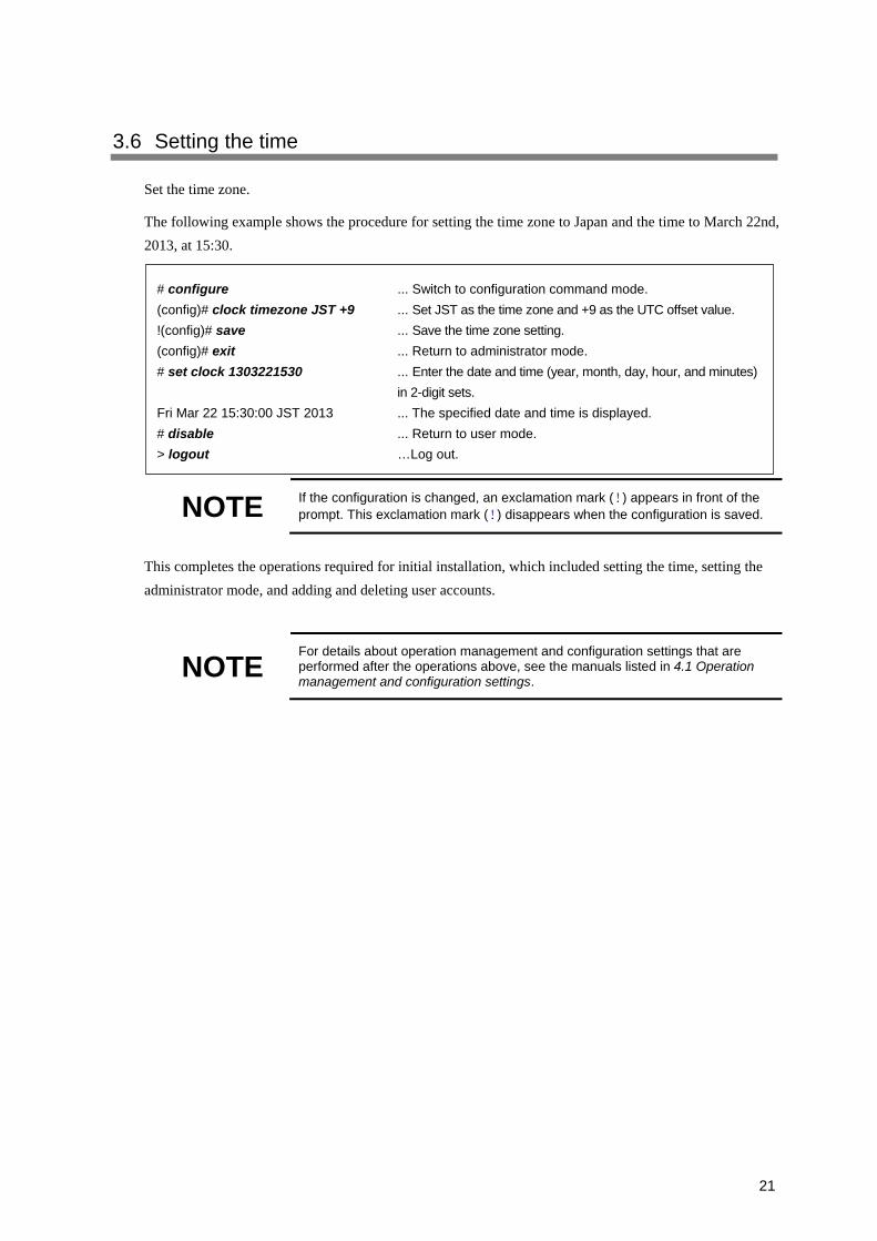
3.6 Setting the time
Set the time zone.
The following example shows the procedure for setting the time zone to Japan and the time to March 22nd,
2013, at 15:30.
NOTE If the configuration is changed, an exclamation mark (!) appears in front of the prompt. This exclamation mark (!) disappears when the configuration is saved.
This completes the operations required for initial installation, which included setting the time, setting the
administrator mode, and adding and deleting user accounts.
NOTE For details about operation management and configuration settings that are performed after the operations above, see the manuals listed in 4.1 Operation management and configuration settings.
# configure ... Switch to configuration command mode.
(config)# clock timezone JST +9 ... Set JST as the time zone and +9 as the UTC offset value.
!(config)# save ... Save the time zone setting.
(config)# exit ... Return to administrator mode.
# set clock 1303221530 ... Enter the date and time (year, month, day, hour, and minutes)
in 2-digit sets.
Fri Mar 22 15:30:00 JST 2013 ... The specified date and time is displayed.
# disable ... Return to user mode.
> logout …Log out.

22

23
4 Operations After Installation
This chapter describes the manuals you need to reference to specify advanced settings for the Device, check the operating status, and troubleshoot any problem that might occur.
4.1 Operation management and configuration settings
4.2 Troubleshooting

24
4.1 Operation management and configuration settings
For details about operation management and configuration settings, see the manuals below. (Numbers in
parentheses indicate the manual number.)
Manuals for operation management and configuration settings:
- Software Manual Configuration Guide Vol. 1 (AX86R-S001X)
- Software Manual Configuration Guide Vol. 2 (AX86R-S002X)
- Software Manual Configuration Guide Vol. 3 (AX86R-S003X)
Manuals for detailed configuration commands:
- Software Manual Configuration Command Reference Vol. 1 (AX86R-S004X)
- Software Manual Configuration Command Reference Vol. 2 (AX86R-S005X)
- Software Manual Configuration Command Reference Vol. 3 (AX86R-S006X)
Manuals for detailed operation commands:
- Software Manual Operation Command Reference Vol. 1 (AX86R-S007X)
- Software Manual Operation Command Reference Vol. 2 (AX86R-S008X)
- Software Manual Operation Command Reference Vol. 3 (AX86R-S009X)
NOTE
After setting up a configuration, make sure that you back up the operation information. This enables the operation information to be restored easily after the basic control unit is replaced in the event of a failure. For details about the backup procedure, see 11 Device Management in the Software Manual Configuration Guide Vol. 1.
25
4.2 Troubleshooting
For details about how to troubleshoot when a problem occurs, see the corresponding manual shown below.
(Numbers in parentheses indicate the manual number.)
- Troubleshooting Guide (AX86R-T001X)