Embed Size (px)
Citation preview
ALASKA STAND ALONE PIPELINE/ASAP
PROJECT
DRAFT Wetlands Compensatory Mitigation Plan
ASAP-22-PLN-REG-DOC-00001
November 10, 2016
DRAFT Wetlands Compensatory Mitigation Plan
Document No: ASAP 22-PLN-REG-DOC-00001 Date: November 10, 2016 Page ii NOTICE – THIS DOCUMENT CONTAINS CONFIDENTIAL AND PROPRIETARY INFORMATION AND SHALL NOT BE DUPLICATED, DISTRIBUTED, DISCLOSED, SHARED OR USED FOR ANY PURPOSE EXCEPT AS MAY BE AUTHORIZED BY AGDC IN WRITING. THIS DOCUMENT IS UNCONTROLLED WHEN PRINTED. THIS COPY VALID ONLY AT THE TIME OF PRINTING
REVISION HISTORY
Revision Date Comment Approval
Company Preparing Report AGDC
0 11/10/2016 Draft AGDC K Stevenson / M Thompson

DRAFT Wetlands Compensatory Mitigation Plan
Document No: ASAP 22-PLN-REG-DOC-00001 Date: November 10, 2016 Page iii NOTICE – THIS DOCUMENT CONTAINS CONFIDENTIAL AND PROPRIETARY INFORMATION AND SHALL NOT BE DUPLICATED, DISTRIBUTED, DISCLOSED, SHARED OR USED FOR ANY PURPOSE EXCEPT AS MAY BE AUTHORIZED BY AGDC IN WRITING. THIS DOCUMENT IS UNCONTROLLED WHEN PRINTED. THIS COPY VALID ONLY AT THE TIME OF PRINTING
ACRONYMS AND ABBREVIATIONS
ADF&G Alaska Department of Fish and Game
ADNR-PMC Alaska Department of Natural Resources – Plant Materials Center
ADPOT&PF Alaska Department of Transportation and Public Facilities
AES ASRC Energy Services
AGDC Alaska Gasline Development Corporation
AKWAM Alaska Wetland Assessment Method
AKLNG Alaska LNG
ARR Alaska Railroad
ASAP Alaska Stand Alone Pipeline
ASA Aquatic Site Assessment
ASRC Arctic Slope Regional Corporation
CEQ Council on Environmental Quality
CFR Code of Federal Regulations
CMP Wetland Compensatory Mitigation Plan
DA Department of the Army
EED Environmental Evaluation Document ENSTAR
EPA United States Environmental Protection Agency
ERL Environmental, Regulatory, and Land
FCI Functional Capacity Index
FEIS Final Environmental Impact Statement
ft Foot / feet
GCF Gas Conditioning Facility
HDD Horizontal directional drilling
HGM hydrogeomorphic
HUC Hydrologic Unit
ILF in-lieu fee
LEDPA Least Environmentally Damaging Practicable Alternative
Mat-Su Matanuska-Susitna
MSB Matanuska-Susitna Borough
DRAFT Wetlands Compensatory Mitigation Plan
Document No: ASAP 22-PLN-REG-DOC-00001 Date: November 10, 2016 Page iv NOTICE – THIS DOCUMENT CONTAINS CONFIDENTIAL AND PROPRIETARY INFORMATION AND SHALL NOT BE DUPLICATED, DISTRIBUTED, DISCLOSED, SHARED OR USED FOR ANY PURPOSE EXCEPT AS MAY BE AUTHORIZED BY AGDC IN WRITING. THIS DOCUMENT IS UNCONTROLLED WHEN PRINTED. THIS COPY VALID ONLY AT THE TIME OF PRINTING
MMscfd Million cubic feet per day
MP Mile post
MRLC Multi-Resolution Land Characteristics
NHD National Hydrography Database
NWI National Wetlands Inventory
NLCD National Land Cover Database
PI Point of Intersection
PRM permittee-responsible mitigation
ROW Rights-of-Way
SDA Special Design Area
SEAL Trust Southeast Alaska Land Trust
SEIS Supplemental Environmental Impact Statement
SOA State of Alaska
TAPS Trans-Alaska Pipeline System
TCF The Conservation Fund
TW Temporary workspaces
USACE United States Army Corps of Engineers
v Version/Revision of the ASAP pipeline route alignment
WOUS Waters of the United States
DRAFT Wetlands Compensatory Mitigation Plan
Document No: ASAP 22-PLN-REG-DOC-00001 Date: November 10, 2016 Page v NOTICE – THIS DOCUMENT CONTAINS CONFIDENTIAL AND PROPRIETARY INFORMATION AND SHALL NOT BE DUPLICATED, DISTRIBUTED, DISCLOSED, SHARED OR USED FOR ANY PURPOSE EXCEPT AS MAY BE AUTHORIZED BY AGDC IN WRITING. THIS DOCUMENT IS UNCONTROLLED WHEN PRINTED. THIS COPY VALID ONLY AT THE TIME OF PRINTING
TABLE OF CONTENTS
1. Introduction ............................................................................................................................ 1
1.1 Purpose ............................................................................................................................ 1 1.2 Watershed Approach to Compensatory Mitigation ......................................................... 1 1.3 Regulatory Guidance for Avoidance, Minimization, and Compensatory Mitigation of
Wetland Impacts ............................................................................................................. 2
2. Avoidance and Minimization of Wetlands ........................................................................... 5
2.1 Project Description .......................................................................................................... 5 2.2 Route Refinements ........................................................................................................... 7
2.2.1 Alignment v5.0 (FEIS) ..................................................................................... 7 2.2.2 Alignment v6.1 (Supplemental FEIS) .............................................................. 8
2.3 Routing Alternatives Considered ................................................................................... 18 2.3.1 Project 404(b)(1) Alternatives Analysis ......................................................... 18 2.3.2 Alaska Intertie Route Variation ...................................................................... 19 2.3.3 Denali National Park Route Variation ............................................................ 19 2.3.4 Alaska Railroad Route Variations .................................................................. 19 2.3.5 Curry Rail Route Variation............................................................................. 20 2.3.6 Port MacKenzie Rail Route Variation ............................................................ 20
2.4 Additional Avoidance .................................................................................................... 20 2.4.1 Ice Roads ........................................................................................................ 20 2.4.2 Ice Pads and Snow Packing ............................................................................ 20 2.4.3 Preferential Use of Uplands or Previously Disturbed Areas .......................... 20 2.4.4 Open Water Avoidance .................................................................................. 21 2.4.5 Material Sites (Borrow) .................................................................................. 21 2.4.6 Access Roads .................................................................................................. 22 2.4.7 Collocation of Facilities.................................................................................. 22
2.5 Additional Minimization................................................................................................ 23 2.5.1 Temporary Facilities ....................................................................................... 23 2.5.2 Revegetation ................................................................................................... 23
2.6 Water Crossings and Water Management...................................................................... 24
3. Determination of Substantive Watershed Impacts ........................................................... 27
3.1 Estimating Anthorpogenic Disturbance in the Watershed ............................................. 27 3.1.1 National Land Cover Database ....................................................................... 27 3.1.2 Accounting for Anthropogenic Disturbance in the Barren Classification of
the NLCD ....................................................................................................... 31 3.1.3 Results ............................................................................................................ 31
4. Summary of Aquatic Site Assessment ................................................................................ 36
5. Wetlands Debit Calculation Methodology ......................................................................... 39
5.1 Parameters for Wetlands Debit Analysis ....................................................................... 39
DRAFT Wetlands Compensatory Mitigation Plan
Document No: ASAP 22-PLN-REG-DOC-00001 Date: November 10, 2016 Page vi NOTICE – THIS DOCUMENT CONTAINS CONFIDENTIAL AND PROPRIETARY INFORMATION AND SHALL NOT BE DUPLICATED, DISTRIBUTED, DISCLOSED, SHARED OR USED FOR ANY PURPOSE EXCEPT AS MAY BE AUTHORIZED BY AGDC IN WRITING. THIS DOCUMENT IS UNCONTROLLED WHEN PRINTED. THIS COPY VALID ONLY AT THE TIME OF PRINTING
5.1.1 Debit Year ...................................................................................................... 39 5.1.2 Ecoregion ........................................................................................................ 39 5.1.3 10-digit HUC Code ......................................................................................... 39 5.1.4 HGM Classification ........................................................................................ 40
5.2 Summary of Project Wetland Debits ............................................................................. 40
6. Mitigation Options Available .............................................................................................. 41
6.1 Mitigation Banks (Selected) .......................................................................................... 41 6.2 ILF Providers (Not Selected) ......................................................................................... 41
6.2.1 The Conservation Fund .................................................................................. 43 6.2.2 The Proposed State of Alaska ILF Program ................................................... 43
6.3 Permittee Responsible Mitigation (PRM) (not selected) ............................................... 43
7. Conclusions ........................................................................................................................... 45
Appendix A .................................................................................................................................. 48
Data Validation and Analysis for Existing Anthropogenic Disturbances and Project Wetlands Impacts to Derive a Maximum Disturbed Value (d-value) for HUC-10 Watersheds
DRAFT Wetlands Compensatory Mitigation Plan
Document No: ASAP 22-PLN-REG-DOC-00001 Date: November 10, 2016 Page vii NOTICE – THIS DOCUMENT CONTAINS CONFIDENTIAL AND PROPRIETARY INFORMATION AND SHALL NOT BE DUPLICATED, DISTRIBUTED, DISCLOSED, SHARED OR USED FOR ANY PURPOSE EXCEPT AS MAY BE AUTHORIZED BY AGDC IN WRITING. THIS DOCUMENT IS UNCONTROLLED WHEN PRINTED. THIS COPY VALID ONLY AT THE TIME OF PRINTING
TABLES
Table 1. Mainline Alignment v6.1 Revisions ............................................................................ 9
Table 2. Fairbanks Lateral Revisions – v6.0 to v6.1 ................................................................ 17
Table 3. Notable Off-ROW Revisions – v6.0 to v6.1 .............................................................. 18
Table 4. Reduction in Length and Number of Access Roads from v6.0 to v6.1 ..................... 22
Table 5. Fish and Wildlife Avoidance and Minimization Measures ....................................... 25
Table 6. Summary of Substantive Impacts (Acres) by HUC-10 Watershed ............................ 35
Table 7. Overall Final FCI Score and Category Relationship ................................................. 37
Table 8. Anadromous Buffer Determination ........................................................................... 38
Table 9. Example Debit Calculation ........................................................................................ 38
Table 10. Summary of Wetland Debits by HUC-10 Watershed (AGDC Methodology) .......... 40
DRAFT Wetlands Compensatory Mitigation Plan
Document No: ASAP 22-PLN-REG-DOC-00001 Date: November 10, 2016 Page viii NOTICE – THIS DOCUMENT CONTAINS CONFIDENTIAL AND PROPRIETARY INFORMATION AND SHALL NOT BE DUPLICATED, DISTRIBUTED, DISCLOSED, SHARED OR USED FOR ANY PURPOSE EXCEPT AS MAY BE AUTHORIZED BY AGDC IN WRITING. THIS DOCUMENT IS UNCONTROLLED WHEN PRINTED. THIS COPY VALID ONLY AT THE TIME OF PRINTING
FIGURES
Figure 1. Alaska Stand Alone Pipeline Route ............................................................................. 5
Figure 2. Fairbanks Lateral Route ............................................................................................... 6
Figure 3. NLCD Land Cover Classifications ............................................................................ 28
Figure 4. Fairbanks .................................................................................................................... 29
Figure 5. Rural Disturbance ...................................................................................................... 29
Figure 6. Urban Disturbance ..................................................................................................... 30
Figure 7. Excluded Barren ........................................................................................................ 30
Figure 8. Northern Ecoregion 10-digit HUC Code Areas ......................................................... 32
Figure 9. Interior Ecoregion 10-digit HUC Code Areas ........................................................... 33
Figure 10. Southern Ecoregion 10-digit HUC Code Areas ......................................................... 34
DRAFT Wetlands Compensatory Mitigation Plan
Document No: ASAP 22-PLN-REG-DOC-00001 Date: November 10, 2016 Page 1 NOTICE – THIS DOCUMENT CONTAINS CONFIDENTIAL AND PROPRIETARY INFORMATION AND SHALL NOT BE DUPLICATED, DISTRIBUTED, DISCLOSED, SHARED OR USED FOR ANY PURPOSE EXCEPT AS MAY BE AUTHORIZED BY AGDC IN WRITING. THIS DOCUMENT IS UNCONTROLLED WHEN PRINTED. THIS COPY VALID ONLY AT THE TIME OF PRINTING
1. INTRODUCTION
Compensatory mitigation is a critical tool in helping the federal government meet the longstanding national goal of no net loss of wetland acreage and function (33 Code of Federal Regulations (CFR) Parts 325 and 322; 40 CFR part 230). Compensatory mitigation is considered only after all appro-priate and practicable steps have been taken to first avoid and then minimize adverse impacts to the aquatic ecosystem, pursuant to 40 CFR part 230 (i.e., Clean Water Act Section 404(b)(1) Guide-lines). Compensatory mitigation can be carried out through four methods: restoration of an existing wetland or aquatic site, enhancement of an aquatic site’s function, establishment of a new aquatic site, or preservation of an aquatic site (33 CFR Parts 325 and 332; 40 CFR part 230).
The 2008 Mitigation Rule, published by the United States Army Corps of Engineers (USACE) and the U.S. Environmental Protection Agency (EPA), addresses compensatory mitigation for unavoid-able losses of aquatic resources and functions at a project site (33 CFR Parts 325 and 332; 40 CFR part 230). The rule establishes performance standards, sets timeframes for decision making, and establishes equivalent requirements and standards for the three types of compensatory mitigation: mitigation banks, in-lieu fee (ILF) programs, and permittee-responsible mitigation (PRM) projects.
1.1 PURPOSE
This Wetland Compensatory Mitigation Plan (CMP) describes the procedures by which the Alaska Gasline Development Corporation (AGDC) will compensate for the unavoidable losses of Waters of the United States (WOUS), including wetlands, streams, and creeks within the project area im-pacted by the Alaska Stand Alone Pipeline (ASAP).
1.2 WATERSHED APPROACH TO COMPENSATORY MITIGATION
The ASAP Project will mitigate substantive impacts to wetlands within the watersheds it transects. Substantive impacts are those which would impact the aquatic functions of the watershed in a man-ner that is statistically significant and would require appropriate and practicable mitigation. Much literature has been produced on the impacts of development and urbanization on watersheds and the point at which development significantly impacts the attributes of the watershed’s aquatic re-sources, such as water quality, bank erosion, sedimentation, aquatic habitat, biodiversity, and ma-croinvertebrate, fish, and plant communities.
The consensus among aquatic scientists and landscape ecologists is that statistically significant impacts to the aquatic resources and functions of a watershed occur once approximately 10% of land within a watershed is urbanized (Hilderbrand et al., 2010; Schueler et al., 2009; Booth and
DRAFT Wetlands Compensatory Mitigation Plan
Document No: ASAP 22-PLN-REG-DOC-00001 Date: November 10, 2016 Page 2 NOTICE – THIS DOCUMENT CONTAINS CONFIDENTIAL AND PROPRIETARY INFORMATION AND SHALL NOT BE DUPLICATED, DISTRIBUTED, DISCLOSED, SHARED OR USED FOR ANY PURPOSE EXCEPT AS MAY BE AUTHORIZED BY AGDC IN WRITING. THIS DOCUMENT IS UNCONTROLLED WHEN PRINTED. THIS COPY VALID ONLY AT THE TIME OF PRINTING
Jackson 1997; Booth et al. 1996, Luchetti and Fuersteburg 1993; MWCOG 1992; Booth 1991; Weaver 1991; Limburg and Schmidt 1990; Steedmen 1988; Jones and Clark 1987; Klein 1979). The development of surfaces that are impervious to water (pavement, rooftops, storm drains, ca-nals, etc.) and the introduction of compacted surfaces that reduce absorption of water (gravel roads, gravel pits, agricultural areas) can contribute to these impacts, although impervious surfaces are a larger contributor (Booth and Jackson 1997). An Impervious Cover Model developed from decades of aquatic system research has indicated that, “certain zones of stream quality exist, most notably at about 10% impervious cover, where sensitive stream elements are lost from the system” (Center for Watershed Protection 2016). Others have noted that urbanization begins to have an influence on some biological parameters within watersheds at slightly lower threshold levels, ranging be-tween 5 and 10%, depending on the parameter (Baker and King 2010; Hilderbrand et al., 2010; Utz et al. 2009; Hicks and Larson 1997; May et al. 1997).
The ASAP Project is a long, linear project that crosses 60 10-digit hydrologic unit (HUC) areas, many of which contain very few impervious or compacted surfaces associated with urbanization, as the Project would be constructed and operated in several remote areas where human disturbance is minimal. To determine whether the impacts of the narrow ASAP alignment and related facilities might result in a substantive impact to aquatic resources and functions within the watersheds it transects, AGDC selected a conservative threshold of 7.5 percent of the aggregate existing land-cover impacts and new project wetlands impacts to determine where substantive impacts to aquatic resource functions in watersheds could potentially, thereby requiring mitigation. Rather than using only impervious cover (paved streets, building rooftops, storm drains) in its analysis of existing land impacts, AGDC opted to use a more conservative approach of including all disturbed or com-pacted areas associated with development, including agricultural lands, material sources, and gravel roads, without weighting by impact type. The levels of anthropogenic disturbance (urbanization) in each HUC are reported in this document so that it can be determined whether impacts to the aquatic environment are statistically significant for that watershed and thus require mitigation.
1.3 REGULATORY GUIDANCE FOR AVOIDANCE, MINIMIZATION, AND COMPENSATORY MITIGATION OF WETLAND IMPACTS
Where impacts within a watershed are deemed to be substantive based on the aggregate level of existing disturbance and new project wetlands impact (>7.5% development), appropriate and prac-ticable compensatory mitigation would be applied by AGDC to replace functional losses of aquatic resources and functions. The feasibility and appropriateness of compensatory mitigation for a par-ticular aquatic resource type is to be addressed on a case-by-case basis by district engineers (33 CFR Parts 325 and 332; 40 CFR part 230). The Council on Environmental Quality (CEQ) has defined mitigation to include: avoiding impacts, minimizing impacts, rectifying impacts, reducing impacts over time, and compensating for impacts (40 CFR 1508.20). The types of mitigation enu-merated by the CEQ are compatible with the requirements of the CEQ Guideline. As a practical matter, they are combined by EPA to form three general types: avoidance, minimization and com-pensatory mitigation.
DRAFT Wetlands Compensatory Mitigation Plan
Document No: ASAP 22-PLN-REG-DOC-00001 Date: November 10, 2016 Page 3 NOTICE – THIS DOCUMENT CONTAINS CONFIDENTIAL AND PROPRIETARY INFORMATION AND SHALL NOT BE DUPLICATED, DISTRIBUTED, DISCLOSED, SHARED OR USED FOR ANY PURPOSE EXCEPT AS MAY BE AUTHORIZED BY AGDC IN WRITING. THIS DOCUMENT IS UNCONTROLLED WHEN PRINTED. THIS COPY VALID ONLY AT THE TIME OF PRINTING
1. Avoidance. (see Section 2, below, for ASAP Project approach)
40 CFR 230.10(a) allows permit issuance for only the least environmentally damaging prac-ticable alternative. The thrust of this section on alternatives is avoidance of impacts. Section 230.10(a) requires that no discharge shall be permitted if there is a practicable alternative to the proposed discharge which would have less adverse impact to the aquatic ecosystem, so long as the alternative does not have other significant adverse environmental consequences. In addition, Section 230.10(a)(3) sets forth rebuttable presumptions that 1) alternatives for non-water dependent activities that do not involve special aquatic sites are available and 2) alternatives that do not involve special aquatic sites have less adverse impact on the aquatic environment. Compensatory mitigation may not be used as a method to reduce environmen-tal impacts in the evaluation of the least environmentally damaging practicable alternatives for the purposes of requirements under Section 230.10(a).
2. Minimization. (see Section 2, below, for ASAP Project approach)
40 CFR 230.10(d) states that appropriate and practicable steps to minimize adverse impacts will be required through project modifications and permit conditions. Subpart H of the Guidelines describes means of minimizing impacts of an activity.
3. Compensatory Mitigation. (see Sections 3 - 8, below, for ASAP Project approach)
Appropriate and practicable compensatory mitigation is required for unavoidable adverse impacts which remain after all appropriate and practicable minimization has been required. Compensatory actions (e.g., restoration of existing degraded wetlands or creation of man-made wetlands) should be undertaken when practicable, in areas adjacent or continuous to the discharge site (on-site compensatory mitigation). If on-site compensatory mitigation is not practicable, off-site compensatory mitigation should be undertaken in the same geo-graphic area if appropriate and practicable (i.e., in close proximity and, to the extent possible, the same watershed). In determining compensatory mitigation, the functional values lost by the resource to be impacted must be considered. Generally, in-kind compensatory mitigation is preferable to out-of-kind. There is continued uncertainty regarding the success of wetland creation or other habitat development. Therefore, in determining the nature and extent of habitat development of this type, careful consideration should be given to its likelihood of success. Because the likelihood of success is greater and the impacts to potentially valuable uplands are reduced, restoration should be the first option considered.
A determination of what level of mitigation constitutes appropriate mitigation is based solely on the values and functions of the aquatic resource that will be impacted. Practicable mitigation is defined at Section 230.3(q) of the Guidelines. However, the level of mitigation determined to be appropriate and practicable under Section 230.10(d) may lead to individual permit decisions which do not fully meet this goal because the mitigation measures necessary to meet this goal are not feasible, not practicable, or would accomplish only inconsequential reductions in impacts. Conse-quently, it is recognized by EPA and USACE that the goal of no net loss of wetlands may not be
DRAFT Wetlands Compensatory Mitigation Plan
Document No: ASAP 22-PLN-REG-DOC-00001 Date: November 10, 2016 Page 4 NOTICE – THIS DOCUMENT CONTAINS CONFIDENTIAL AND PROPRIETARY INFORMATION AND SHALL NOT BE DUPLICATED, DISTRIBUTED, DISCLOSED, SHARED OR USED FOR ANY PURPOSE EXCEPT AS MAY BE AUTHORIZED BY AGDC IN WRITING. THIS DOCUMENT IS UNCONTROLLED WHEN PRINTED. THIS COPY VALID ONLY AT THE TIME OF PRINTING
achieved in each and every permit action. In determining appropriate and practicable measures to offset unavoidable impacts to wetlands, mitigation measures must be appropriate to the scope and degree of those impacts and practicable in terms of cost, existing technology, and logistics in light of overall project purposes.
In evaluating Section 404/10 individual permit applications, information on all facets of a project, including mitigation, is typically gathered and reviewed at the same time. USACE usually makes a determination that potential impacts have been avoided to the maximum extent practicable. Re-maining unavoidable impacts will then be mitigated to the extent appropriate and practicable by requiring steps to minimize impacts, and, finally, compensate for aquatic resource values. This sequence is considered satisfied where the proposed mitigation is in accordance with specific pro-visions of a USACE and EPA-approved comprehensive plan that ensures compliance with the com-pensation requirements of the Section 404(b)(1) Guidelines.
A primary goal of the 2008 Mitigation Rule, referenced above, was to improve the quality and success of compensatory mitigation. It emphasized the selection of compensatory mitigation sites on a watershed basis and established equivalent standards and a hierarchy for the three types of compensatory mitigation. A preference hierarchy for mitigation options was established under the 2008 Mitigation Rule to address risk and uncertainty and to address temporal losses of aquatic resource functions (CFR 33 Part 332.3(b); 40 CFR 230.93(b)). There exists a preference for miti-gation banks and ILF programs over PRM projects under the rule unless the PRM is determined to be environmentally preferable. This hierarchy ensures federal agencies that mitigation options with the highest likelihood of success and greatest value to the watershed will be selected from the available choices.
There is generally a preference for use of mitigation bank credits when the permitted activity is in the service area of an approved bank with the appropriate types of credits available. However, in the absence of an approved bank, ILF programs have certain advantages over PRM: ILF programs generally involve large parcels, have access to appropriate scientific and technical expertise, may have a proven track record in establishing successful mitigation, and will generally have a more fully developed watershed approach developed through their required comprehensive planning framework. The federal government does not limit ILF programs to any particular impact type or size (33 CFR Parts 325 and 332; 40 CFR part 230).
DRAFT Wetlands Compensatory Mitigation Plan
Document No: ASAP 22-PLN-REG-DOC-00001 Date: November 10, 2016 Page 5 NOTICE – THIS DOCUMENT CONTAINS CONFIDENTIAL AND PROPRIETARY INFORMATION AND SHALL NOT BE DUPLICATED, DISTRIBUTED, DISCLOSED, SHARED OR USED FOR ANY PURPOSE EXCEPT AS MAY BE AUTHORIZED BY AGDC IN WRITING. THIS DOCUMENT IS UNCONTROLLED WHEN PRINTED. THIS COPY VALID ONLY AT THE TIME OF PRINTING
2. AVOIDANCE AND MINIMIZATION OF WETLANDS
2.1 PROJECT DESCRIPTION
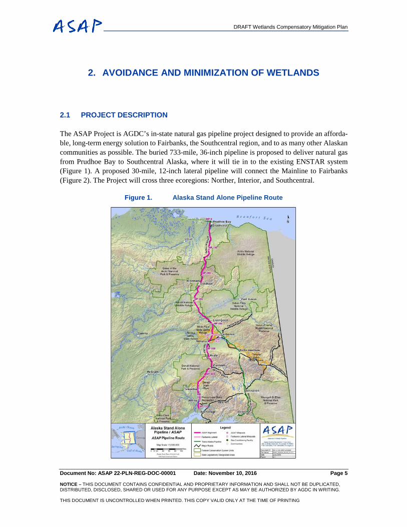
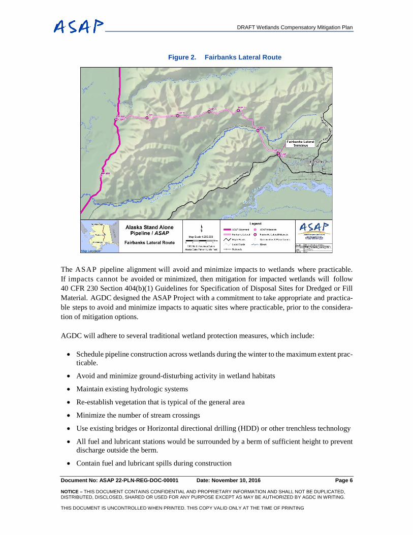
The ASAP Project is AGDC’s in-state natural gas pipeline project designed to provide an afforda-ble, long-term energy solution to Fairbanks, the Southcentral region, and to as many other Alaskan communities as possible. The buried 733-mile, 36-inch pipeline is proposed to deliver natural gas from Prudhoe Bay to Southcentral Alaska, where it will tie in to the existing ENSTAR system (Figure 1). A proposed 30-mile, 12-inch lateral pipeline will connect the Mainline to Fairbanks (Figure 2). The Project will cross three ecoregions: Norther, Interior, and Southcentral.
Figure 1. Alaska Stand Alone Pipeline Route
DRAFT Wetlands Compensatory Mitigation Plan
Document No: ASAP 22-PLN-REG-DOC-00001 Date: November 10, 2016 Page 6 NOTICE – THIS DOCUMENT CONTAINS CONFIDENTIAL AND PROPRIETARY INFORMATION AND SHALL NOT BE DUPLICATED, DISTRIBUTED, DISCLOSED, SHARED OR USED FOR ANY PURPOSE EXCEPT AS MAY BE AUTHORIZED BY AGDC IN WRITING. THIS DOCUMENT IS UNCONTROLLED WHEN PRINTED. THIS COPY VALID ONLY AT THE TIME OF PRINTING
Figure 2. Fairbanks Lateral Route
The ASAP pipeline alignment will avoid and minimize impacts to wetlands where practicable. If impacts cannot be avoided or minimized, then mitigation for impacted wetlands will follow 40 CFR 230 Section 404(b)(1) Guidelines for Specification of Disposal Sites for Dredged or Fill Material. AGDC designed the ASAP Project with a commitment to take appropriate and practica-ble steps to avoid and minimize impacts to aquatic sites where practicable, prior to the considera-tion of mitigation options.
AGDC will adhere to several traditional wetland protection measures, which include:
• Schedule pipeline construction across wetlands during the winter to the maximum extent prac-ticable.
• Avoid and minimize ground-disturbing activity in wetland habitats
• Maintain existing hydrologic systems
• Re-establish vegetation that is typical of the general area
• Minimize the number of stream crossings
• Use existing bridges or Horizontal directional drilling (HDD) or other trenchless technology
• All fuel and lubricant stations would be surrounded by a berm of sufficient height to prevent discharge outside the berm.
• Contain fuel and lubricant spills during construction
DRAFT Wetlands Compensatory Mitigation Plan
Document No: ASAP 22-PLN-REG-DOC-00001 Date: November 10, 2016 Page 7 NOTICE – THIS DOCUMENT CONTAINS CONFIDENTIAL AND PROPRIETARY INFORMATION AND SHALL NOT BE DUPLICATED, DISTRIBUTED, DISCLOSED, SHARED OR USED FOR ANY PURPOSE EXCEPT AS MAY BE AUTHORIZED BY AGDC IN WRITING. THIS DOCUMENT IS UNCONTROLLED WHEN PRINTED. THIS COPY VALID ONLY AT THE TIME OF PRINTING
• Implement procedures to limit spread of non-native invasive plants
• Temporary impact areas disturbed during construction activities would be kept as small as possible.
• Facilities would be situated so the permanent impact area would occupy as much upland hab-itat as can be used.
• Dust abatement measures would be implemented during construction to minimize dust depo-sition in wetlands.
• A stormwater pollution prevention plan and an erosion and sediment control plan would be used to prevent sediment deposition into adjacent wetlands.
2.2 ROUTE REFINEMENTS
A primary method by which the Project avoided and minimized wetland impacts was through the use of a color-coded (stoplight) categorization system to represent the functions and services of delineated waters and wetlands. ASAP staff used this representation of waters and wetlands to refine the pipeline route and site facilities, targeting uplands and avoiding higher value waters and wetlands where practicable. The stoplight categorization identified wetland categories for avoid-ance as follows:
• Red: Waters of the highest value such as streams, lakes, and ponds.
• Yellow: Wetlands of highest value.
• Green: Wetlands of slightly less value than highest value wetlands.
2.2.1 Alignment v5.0 (FEIS)
The prevalence of wetlands along the proposed route, the landscape position of the pipeline rights-of-way (ROW), and engineering constraints to some degree limited the potential for avoidance. As discussed previously in this document, design refinements provided for an incremental reduction in wetland impact.
The v5.0 alignment was evaluated using the latest light detection and ranging imagery and aerial photography overlaid with the v5.0 wetland mapping completed by Arctic Slope Regional Corpo-ration Energy Services (AES). This information was incorporated into the ArcGIS reader to overlay route alignments with natural resources data. The v5.0 alignment was previewed for areas of con-flicts with high-value wetlands: areas defined as emergent wetlands, anadromous fisheries, resident fisheries, open-water ponds, and lakes. The areas were noted by milepost (MP) for field review and verification. The field review team concentrated on avoiding and minimizing as much contact be-tween the mainline and high-value wetland areas as possible.
Each route revision was documented using a Pipeline Route Refinement Form. Information and data related to cost, land, engineering, environmental/regulatory, construction, engineering facili-ties and hydraulics, operations & maintenance (O&M), and stakeholder relations were entered into
DRAFT Wetlands Compensatory Mitigation Plan
Document No: ASAP 22-PLN-REG-DOC-00001 Date: November 10, 2016 Page 8 NOTICE – THIS DOCUMENT CONTAINS CONFIDENTIAL AND PROPRIETARY INFORMATION AND SHALL NOT BE DUPLICATED, DISTRIBUTED, DISCLOSED, SHARED OR USED FOR ANY PURPOSE EXCEPT AS MAY BE AUTHORIZED BY AGDC IN WRITING. THIS DOCUMENT IS UNCONTROLLED WHEN PRINTED. THIS COPY VALID ONLY AT THE TIME OF PRINTING
the forms. Each change form was reviewed and approved in writing by the AGDC Project Manager, AGDC Engineering Manager, ADGC Environmental, Regulatory, and Land (ERL) Manager, and the Michael Baker Jr. Pipeline Manager.
A logic decision tree process was used to help make ROW construction method decisions. Logic trees were developed for both winter and summer construction seasons. Consideration to avoid high-value wetlands was part of the decision tree process.
2.2.2 Alignment v6.1 (Supplemental FEIS)
ASAP project engineers began work on revision v6.0 in 2013 and finalized the route changes in November of that year. The revision v6.0 route changes after the Final Environmental Impact State-ment (FEIS) was completed on revision v5.0 continued the incremental reduction to wetland im-pacts. In late 2014, and at the direction of the AGDC Board of Directors, the ASAP project team worked collaboratively with members of the Alaska LNG (AKLNG) project team to agree upon a common alignment for the portions of the two routes that overlap. This effort used the best available engineering and environmental knowledge to avoid physical hazards, minimize impacts to wetlands and other resources, and take into account Supplemental Environmental Impact Statement (SEIS) scoping comments. The more significant changes are as follows:
• Near Toolik Lake, where a corner was transected to reduce length.
• In Minto area, where the alignment was moved from the flats lowlands to the ridgeline, reducing wetlands impact and reducing construction risk.
• Near Healy, where the alignment was moved to the west to avoid the more populated areas of Healy.
• Near Cantwell, where the line was moved to the east and up on the ridgeline to avoid going through the more populated areas of Cantwell.
• In Hurricane Gulch area, where the alignment was moved upslope to the east to provide a better crossing of Hurricane Gulch.
• Near the Alaska Veteran’s Memorial, where the alignment was moved toward the west to reduce visual impact.
• After crossing the Chulitna River, where the alignment was moved further to the west to reduce visual impact.
• South of Talkeetna, where the alignment was moved both west and east to optimize stream crossings and reduce impacts to the more populated areas.
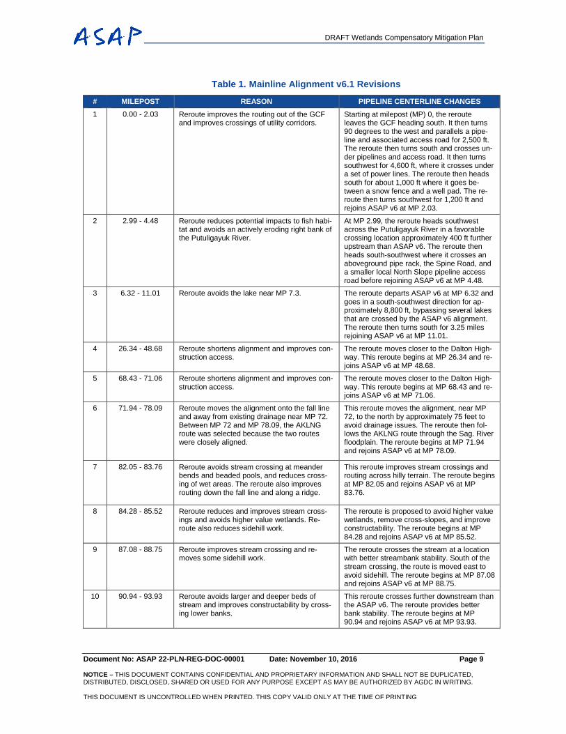
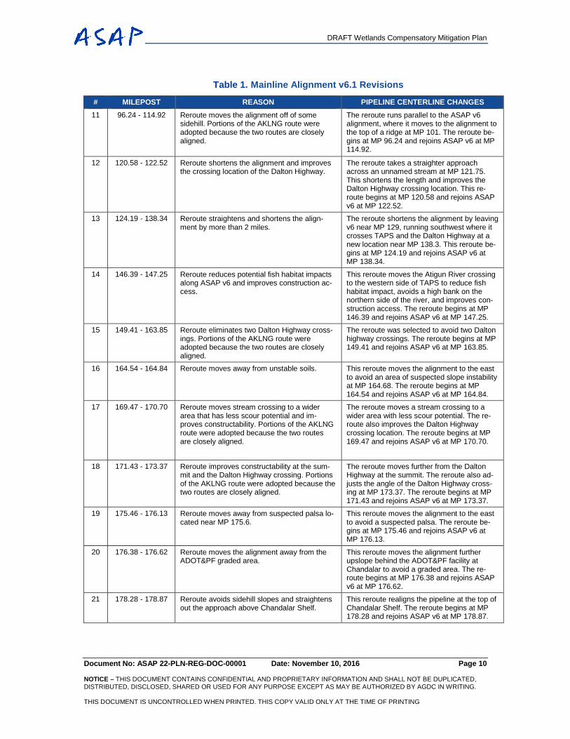
Tables 1 - 3 provide descriptions of alignment shifts that were made in early 2015, along with the reasons for the changes. The tables illustrate that many of the changes made were to avoid wetlands or to change stream/drainage crossings to minimize wetland impact and reduce possible erosion. The same considerations were applied to the layout of access roads and other off-ROW facilities.
DRAFT Wetlands Compensatory Mitigation Plan
Document No: ASAP 22-PLN-REG-DOC-00001 Date: November 10, 2016 Page 9 NOTICE – THIS DOCUMENT CONTAINS CONFIDENTIAL AND PROPRIETARY INFORMATION AND SHALL NOT BE DUPLICATED, DISTRIBUTED, DISCLOSED, SHARED OR USED FOR ANY PURPOSE EXCEPT AS MAY BE AUTHORIZED BY AGDC IN WRITING. THIS DOCUMENT IS UNCONTROLLED WHEN PRINTED. THIS COPY VALID ONLY AT THE TIME OF PRINTING
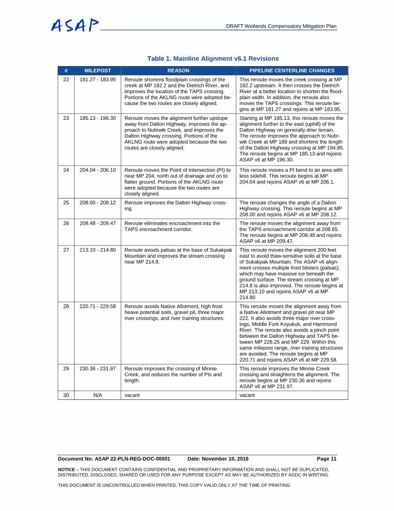
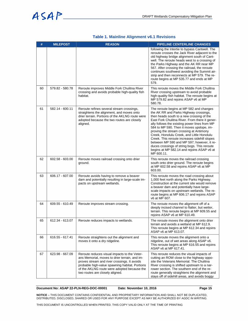
Table 1. Mainline Alignment v6.1 Revisions
# MILEPOST REASON PIPELINE CENTERLINE CHANGES 1 0.00 - 2.03 Reroute improves the routing out of the GCF
and improves crossings of utility corridors. Starting at milepost (MP) 0, the reroute leaves the GCF heading south. It then turns 90 degrees to the west and parallels a pipe-line and associated access road for 2,500 ft. The reroute then turns south and crosses un-der pipelines and access road. It then turns southwest for 4,600 ft, where it crosses under a set of power lines. The reroute then heads south for about 1,000 ft where it goes be-tween a snow fence and a well pad. The re-route then turns southwest for 1,200 ft and rejoins ASAP v6 at MP 2.03.
2 2.99 - 4.48 Reroute reduces potential impacts to fish habi-tat and avoids an actively eroding right bank of the Putuligayuk River.
At MP 2.99, the reroute heads southwest across the Putuligayuk River in a favorable crossing location approximately 400 ft further upstream than ASAP v6. The reroute then heads south-southwest where it crosses an aboveground pipe rack, the Spine Road, and a smaller local North Slope pipeline access road before rejoining ASAP v6 at MP 4.48.
3 6.32 - 11.01 Reroute avoids the lake near MP 7.3. The reroute departs ASAP v6 at MP 6.32 and goes in a south-southwest direction for ap-proximately 8,800 ft, bypassing several lakes that are crossed by the ASAP v6 alignment. The reroute then turns south for 3.25 miles rejoining ASAP v6 at MP 11.01.
4 26.34 - 48.68 Reroute shortens alignment and improves con-struction access.
The reroute moves closer to the Dalton High-way. This reroute begins at MP 26.34 and re-joins ASAP v6 at MP 48.68.
5 68.43 - 71.06 Reroute shortens alignment and improves con-struction access.
The reroute moves closer to the Dalton High-way. This reroute begins at MP 68.43 and re-joins ASAP v6 at MP 71.06.
6 71.94 - 78.09 Reroute moves the alignment onto the fall line and away from existing drainage near MP 72. Between MP 72 and MP 78.09, the AKLNG route was selected because the two routes were closely aligned.
This reroute moves the alignment, near MP 72, to the north by approximately 75 feet to avoid drainage issues. The reroute then fol-lows the AKLNG route through the Sag. River floodplain. The reroute begins at MP 71.94 and rejoins ASAP v6 at MP 78.09.
7 82.05 - 83.76 Reroute avoids stream crossing at meander bends and beaded pools, and reduces cross-ing of wet areas. The reroute also improves routing down the fall line and along a ridge.
This reroute improves stream crossings and routing across hilly terrain. The reroute begins at MP 82.05 and rejoins ASAP v6 at MP 83.76.
8 84.28 - 85.52 Reroute reduces and improves stream cross-ings and avoids higher value wetlands. Re-route also reduces sidehill work.
The reroute is proposed to avoid higher value wetlands, remove cross-slopes, and improve constructability. The reroute begins at MP 84.28 and rejoins ASAP v6 at MP 85.52.
9 87.08 - 88.75 Reroute improves stream crossing and re-moves some sidehill work.
The reroute crosses the stream at a location with better streambank stability. South of the stream crossing, the route is moved east to avoid sidehill. The reroute begins at MP 87.08 and rejoins ASAP v6 at MP 88.75.
10 90.94 - 93.93 Reroute avoids larger and deeper beds of stream and improves constructability by cross-ing lower banks.
This reroute crosses further downstream than the ASAP v6. The reroute provides better bank stability. The reroute begins at MP 90.94 and rejoins ASAP v6 at MP 93.93.
DRAFT Wetlands Compensatory Mitigation Plan
Document No: ASAP 22-PLN-REG-DOC-00001 Date: November 10, 2016 Page 10 NOTICE – THIS DOCUMENT CONTAINS CONFIDENTIAL AND PROPRIETARY INFORMATION AND SHALL NOT BE DUPLICATED, DISTRIBUTED, DISCLOSED, SHARED OR USED FOR ANY PURPOSE EXCEPT AS MAY BE AUTHORIZED BY AGDC IN WRITING. THIS DOCUMENT IS UNCONTROLLED WHEN PRINTED. THIS COPY VALID ONLY AT THE TIME OF PRINTING
Table 1. Mainline Alignment v6.1 Revisions
# MILEPOST REASON PIPELINE CENTERLINE CHANGES 11 96.24 - 114.92 Reroute moves the alignment off of some
sidehill. Portions of the AKLNG route were adopted because the two routes are closely aligned.
The reroute runs parallel to the ASAP v6 alignment, where it moves to the alignment to the top of a ridge at MP 101. The reroute be-gins at MP 96.24 and rejoins ASAP v6 at MP 114.92.
12 120.58 - 122.52 Reroute shortens the alignment and improves the crossing location of the Dalton Highway.
The reroute takes a straighter approach across an unnamed stream at MP 121.75. This shortens the length and improves the Dalton Highway crossing location. This re-route begins at MP 120.58 and rejoins ASAP v6 at MP 122.52.
13 124.19 - 138.34 Reroute straightens and shortens the align-ment by more than 2 miles.
The reroute shortens the alignment by leaving v6 near MP 129, running southwest where it crosses TAPS and the Dalton Highway at a new location near MP 138.3. This reroute be-gins at MP 124.19 and rejoins ASAP v6 at MP 138.34.
14 146.39 - 147.25 Reroute reduces potential fish habitat impacts along ASAP v6 and improves construction ac-cess.
This reroute moves the Atigun River crossing to the western side of TAPS to reduce fish habitat impact, avoids a high bank on the northern side of the river, and improves con-struction access. The reroute begins at MP 146.39 and rejoins ASAP v6 at MP 147.25.
15 149.41 - 163.85 Reroute eliminates two Dalton Highway cross-ings. Portions of the AKLNG route were adopted because the two routes are closely aligned.
The reroute was selected to avoid two Dalton highway crossings. The reroute begins at MP 149.41 and rejoins ASAP v6 at MP 163.85.
16 164.54 - 164.84 Reroute moves away from unstable soils. This reroute moves the alignment to the east to avoid an area of suspected slope instability at MP 164.68. The reroute begins at MP 164.54 and rejoins ASAP v6 at MP 164.84.
17 169.47 - 170.70 Reroute moves stream crossing to a wider area that has less scour potential and im-proves constructability. Portions of the AKLNG route were adopted because the two routes are closely aligned.
The reroute moves a stream crossing to a wider area with less scour potential. The re-route also improves the Dalton Highway crossing location. The reroute begins at MP 169.47 and rejoins ASAP v6 at MP 170.70.
18 171.43 - 173.37 Reroute improves constructability at the sum-mit and the Dalton Highway crossing. Portions of the AKLNG route were adopted because the two routes are closely aligned.
The reroute moves further from the Dalton Highway at the summit. The reroute also ad-justs the angle of the Dalton Highway cross-ing at MP 173.37. The reroute begins at MP 171.43 and rejoins ASAP v6 at MP 173.37.
19 175.46 - 176.13 Reroute moves away from suspected palsa lo-cated near MP 175.6.
This reroute moves the alignment to the east to avoid a suspected palsa. The reroute be-gins at MP 175.46 and rejoins ASAP v6 at MP 176.13.
20 176.38 - 176.62 Reroute moves the alignment away from the ADOT&PF graded area.
This reroute moves the alignment further upslope behind the ADOT&PF facility at Chandalar to avoid a graded area. The re-route begins at MP 176.38 and rejoins ASAP v6 at MP 176.62.
21 178.28 - 178.87 Reroute avoids sidehill slopes and straightens out the approach above Chandalar Shelf.
This reroute realigns the pipeline at the top of Chandalar Shelf. The reroute begins at MP 178.28 and rejoins ASAP v6 at MP 178.87.
DRAFT Wetlands Compensatory Mitigation Plan
Document No: ASAP 22-PLN-REG-DOC-00001 Date: November 10, 2016 Page 11 NOTICE – THIS DOCUMENT CONTAINS CONFIDENTIAL AND PROPRIETARY INFORMATION AND SHALL NOT BE DUPLICATED, DISTRIBUTED, DISCLOSED, SHARED OR USED FOR ANY PURPOSE EXCEPT AS MAY BE AUTHORIZED BY AGDC IN WRITING. THIS DOCUMENT IS UNCONTROLLED WHEN PRINTED. THIS COPY VALID ONLY AT THE TIME OF PRINTING
Table 1. Mainline Alignment v6.1 Revisions
# MILEPOST REASON PIPELINE CENTERLINE CHANGES 22 181.27 - 183.95 Reroute shortens floodplain crossings of the
creek at MP 182.2 and the Dietrich River, and improves the location of the TAPS crossing. Portions of the AKLNG route were adopted be-cause the two routes are closely aligned.
This reroute moves the creek crossing at MP 182.2 upstream. It then crosses the Dietrich River at a better location to shorten the flood-plain width. In addition, the reroute also moves the TAPS crossings. This reroute be-gins at MP 181.27 and rejoins at MP 183.95.
23 185.13 - 196.30 Reroute moves the alignment further upslope away from Dalton Highway, improves the ap-proach to Nutirwik Creek, and improves the Dalton Highway crossing. Portions of the AKLNG route were adopted because the two routes are closely aligned.
Starting at MP 185.13, this reroute moves the alignment further to the east (uphill) of the Dalton Highway on generally drier terrain. The reroute improves the approach to Nutir-wik Creek at MP 189 and shortens the length of the Dalton Highway crossing at MP 194.85. The reroute begins at MP 185.13 and rejoins ASAP v6 at MP 196.30.
24 204.04 - 206.10 Reroute moves the Point of Intersection (PI) to near MP 204, north out of drainage and on to flatter ground. Portions of the AKLNG route were adopted because the two routes are closely aligned.
This reroute moves a PI bend to an area with less sidehill. This reroute begins at MP 204.04 and rejoins ASAP v6 at MP 206.1.
25 208.00 - 208.12 Reroute improves the Dalton Highway cross-ing.
The reroute changes the angle of a Dalton Highway crossing. This reroute begins at MP 208.00 and rejoins ASAP v6 at MP 208.12.
26 208.48 - 209.47 Reroute eliminates encroachment into the TAPS encroachment corridor.
The reroute moves the alignment away from the TAPS encroachment corridor at 208.65. The reroute begins at MP 208.48 and rejoins ASAP v6 at MP 209.47.
27 213.10 - 214.80 Reroute avoids palsas at the base of Sukakpak Mountain and improves the stream crossing near MP 214.8.
This reroute moves the alignment 200 feet east to avoid thaw-sensitive soils at the base of Sukakpak Mountain. The ASAP v6 align-ment crosses multiple frost blisters (palsas), which may have massive ice beneath the ground surface. The stream crossing at MP 214.8 is also improved. The reroute begins at MP 213.10 and rejoins ASAP v6 at MP 214.80
28 220.71 - 229.58 Reroute avoids Native Allotment, high frost heave potential soils, gravel pit, three major river crossings, and river training structures.
This reroute moves the alignment away from a Native Allotment and gravel pit near MP 222. It also avoids three major river cross-ings, Middle Fork Koyukuk, and Hammond River. The reroute also avoids a pinch point between the Dalton Highway and TAPS be-tween MP 228.25 and MP 229. Within this same milepost range, river training structures are avoided. The reroute begins at MP 220.71 and rejoins ASAP v6 at MP 229.58.
29 230.36 - 231.97 Reroute improves the crossing of Minnie Creek, and reduces the number of PIs and length.
This reroute improves the Minnie Creek crossing and straightens the alignment. The reroute begins at MP 230.36 and rejoins ASAP v6 at MP 231.97.
30 N/A vacant vacant
DRAFT Wetlands Compensatory Mitigation Plan
Document No: ASAP 22-PLN-REG-DOC-00001 Date: November 10, 2016 Page 12 NOTICE – THIS DOCUMENT CONTAINS CONFIDENTIAL AND PROPRIETARY INFORMATION AND SHALL NOT BE DUPLICATED, DISTRIBUTED, DISCLOSED, SHARED OR USED FOR ANY PURPOSE EXCEPT AS MAY BE AUTHORIZED BY AGDC IN WRITING. THIS DOCUMENT IS UNCONTROLLED WHEN PRINTED. THIS COPY VALID ONLY AT THE TIME OF PRINTING
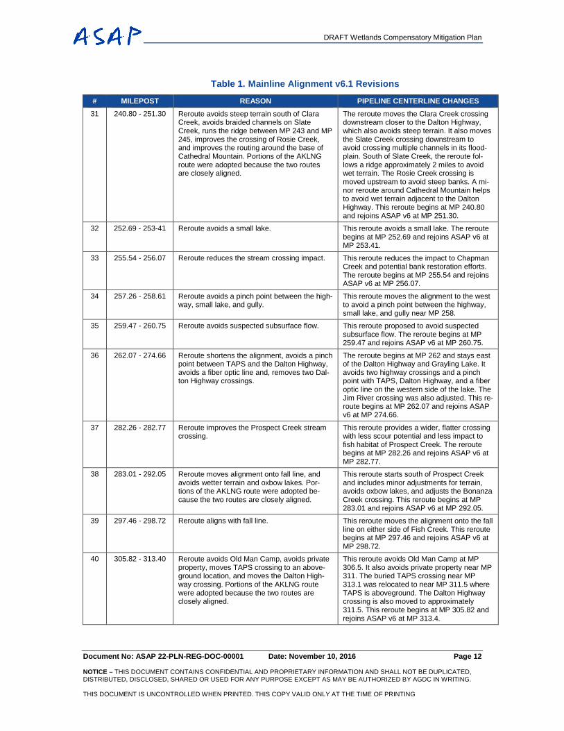
Table 1. Mainline Alignment v6.1 Revisions
# MILEPOST REASON PIPELINE CENTERLINE CHANGES 31 240.80 - 251.30 Reroute avoids steep terrain south of Clara
Creek, avoids braided channels on Slate Creek, runs the ridge between MP 243 and MP 245, improves the crossing of Rosie Creek, and improves the routing around the base of Cathedral Mountain. Portions of the AKLNG route were adopted because the two routes are closely aligned.
The reroute moves the Clara Creek crossing downstream closer to the Dalton Highway, which also avoids steep terrain. It also moves the Slate Creek crossing downstream to avoid crossing multiple channels in its flood-plain. South of Slate Creek, the reroute fol-lows a ridge approximately 2 miles to avoid wet terrain. The Rosie Creek crossing is moved upstream to avoid steep banks. A mi-nor reroute around Cathedral Mountain helps to avoid wet terrain adjacent to the Dalton Highway. This reroute begins at MP 240.80 and rejoins ASAP v6 at MP 251.30.
32 252.69 - 253-41 Reroute avoids a small lake. This reroute avoids a small lake. The reroute begins at MP 252.69 and rejoins ASAP v6 at MP 253.41.
33 255.54 - 256.07 Reroute reduces the stream crossing impact. This reroute reduces the impact to Chapman Creek and potential bank restoration efforts. The reroute begins at MP 255.54 and rejoins ASAP v6 at MP 256.07.
34 257.26 - 258.61 Reroute avoids a pinch point between the high-way, small lake, and gully.
This reroute moves the alignment to the west to avoid a pinch point between the highway, small lake, and gully near MP 258.
35 259.47 - 260.75 Reroute avoids suspected subsurface flow. This reroute proposed to avoid suspected subsurface flow. The reroute begins at MP 259.47 and rejoins ASAP v6 at MP 260.75.
36 262.07 - 274.66 Reroute shortens the alignment, avoids a pinch point between TAPS and the Dalton Highway, avoids a fiber optic line and, removes two Dal-ton Highway crossings.
The reroute begins at MP 262 and stays east of the Dalton Highway and Grayling Lake. It avoids two highway crossings and a pinch point with TAPS, Dalton Highway, and a fiber optic line on the western side of the lake. The Jim River crossing was also adjusted. This re-route begins at MP 262.07 and rejoins ASAP v6 at MP 274.66.
37 282.26 - 282.77 Reroute improves the Prospect Creek stream crossing.
This reroute provides a wider, flatter crossing with less scour potential and less impact to fish habitat of Prospect Creek. The reroute begins at MP 282.26 and rejoins ASAP v6 at MP 282.77.
38 283.01 - 292.05 Reroute moves alignment onto fall line, and avoids wetter terrain and oxbow lakes. Por-tions of the AKLNG route were adopted be-cause the two routes are closely aligned.
This reroute starts south of Prospect Creek and includes minor adjustments for terrain, avoids oxbow lakes, and adjusts the Bonanza Creek crossing. This reroute begins at MP 283.01 and rejoins ASAP v6 at MP 292.05.
39 297.46 - 298.72 Reroute aligns with fall line. This reroute moves the alignment onto the fall line on either side of Fish Creek. This reroute begins at MP 297.46 and rejoins ASAP v6 at MP 298.72.
40 305.82 - 313.40 Reroute avoids Old Man Camp, avoids private property, moves TAPS crossing to an above-ground location, and moves the Dalton High-way crossing. Portions of the AKLNG route were adopted because the two routes are closely aligned.
This reroute avoids Old Man Camp at MP 306.5. It also avoids private property near MP 311. The buried TAPS crossing near MP 313.1 was relocated to near MP 311.5 where TAPS is aboveground. The Dalton Highway crossing is also moved to approximately 311.5. This reroute begins at MP 305.82 and rejoins ASAP v6 at MP 313.4.
DRAFT Wetlands Compensatory Mitigation Plan
Document No: ASAP 22-PLN-REG-DOC-00001 Date: November 10, 2016 Page 13 NOTICE – THIS DOCUMENT CONTAINS CONFIDENTIAL AND PROPRIETARY INFORMATION AND SHALL NOT BE DUPLICATED, DISTRIBUTED, DISCLOSED, SHARED OR USED FOR ANY PURPOSE EXCEPT AS MAY BE AUTHORIZED BY AGDC IN WRITING. THIS DOCUMENT IS UNCONTROLLED WHEN PRINTED. THIS COPY VALID ONLY AT THE TIME OF PRINTING
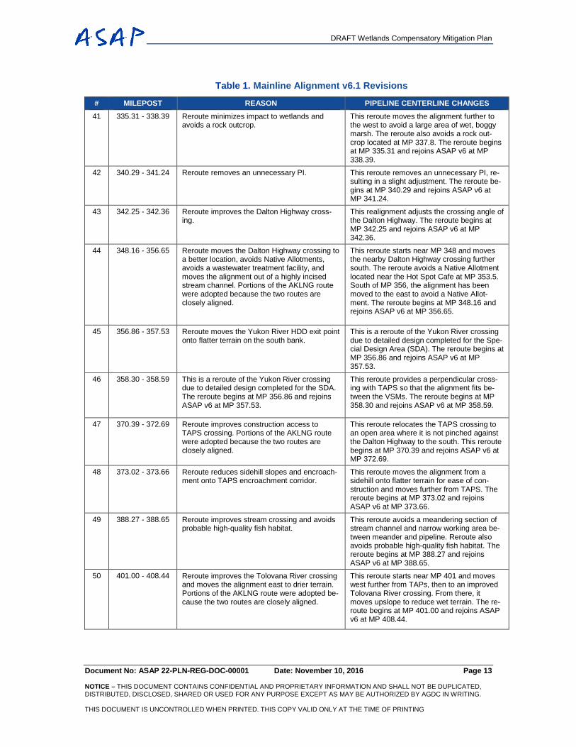
Table 1. Mainline Alignment v6.1 Revisions
# MILEPOST REASON PIPELINE CENTERLINE CHANGES 41 335.31 - 338.39 Reroute minimizes impact to wetlands and
avoids a rock outcrop. This reroute moves the alignment further to the west to avoid a large area of wet, boggy marsh. The reroute also avoids a rock out-crop located at MP 337.8. The reroute begins at MP 335.31 and rejoins ASAP v6 at MP 338.39.
42 340.29 - 341.24 Reroute removes an unnecessary PI. This reroute removes an unnecessary PI, re-sulting in a slight adjustment. The reroute be-gins at MP 340.29 and rejoins ASAP v6 at MP 341.24.
43 342.25 - 342.36 Reroute improves the Dalton Highway cross-ing.
This realignment adjusts the crossing angle of the Dalton Highway. The reroute begins at MP 342.25 and rejoins ASAP v6 at MP 342.36.
44 348.16 - 356.65 Reroute moves the Dalton Highway crossing to a better location, avoids Native Allotments, avoids a wastewater treatment facility, and moves the alignment out of a highly incised stream channel. Portions of the AKLNG route were adopted because the two routes are closely aligned.
This reroute starts near MP 348 and moves the nearby Dalton Highway crossing further south. The reroute avoids a Native Allotment located near the Hot Spot Cafe at MP 353.5. South of MP 356, the alignment has been moved to the east to avoid a Native Allot-ment. The reroute begins at MP 348.16 and rejoins ASAP v6 at MP 356.65.
45 356.86 - 357.53 Reroute moves the Yukon River HDD exit point onto flatter terrain on the south bank.
This is a reroute of the Yukon River crossing due to detailed design completed for the Spe-cial Design Area (SDA). The reroute begins at MP 356.86 and rejoins ASAP v6 at MP 357.53.
46 358.30 - 358.59 This is a reroute of the Yukon River crossing due to detailed design completed for the SDA. The reroute begins at MP 356.86 and rejoins ASAP v6 at MP 357.53.
This reroute provides a perpendicular cross-ing with TAPS so that the alignment fits be-tween the VSMs. The reroute begins at MP 358.30 and rejoins ASAP v6 at MP 358.59.
47 370.39 - 372.69 Reroute improves construction access to TAPS crossing. Portions of the AKLNG route were adopted because the two routes are closely aligned.
This reroute relocates the TAPS crossing to an open area where it is not pinched against the Dalton Highway to the south. This reroute begins at MP 370.39 and rejoins ASAP v6 at MP 372.69.
48 373.02 - 373.66 Reroute reduces sidehill slopes and encroach-ment onto TAPS encroachment corridor.
This reroute moves the alignment from a sidehill onto flatter terrain for ease of con-struction and moves further from TAPS. The reroute begins at MP 373.02 and rejoins ASAP v6 at MP 373.66.
49 388.27 - 388.65 Reroute improves stream crossing and avoids probable high-quality fish habitat.
This reroute avoids a meandering section of stream channel and narrow working area be-tween meander and pipeline. Reroute also avoids probable high-quality fish habitat. The reroute begins at MP 388.27 and rejoins ASAP v6 at MP 388.65.
50 401.00 - 408.44 Reroute improves the Tolovana River crossing and moves the alignment east to drier terrain. Portions of the AKLNG route were adopted be-cause the two routes are closely aligned.
This reroute starts near MP 401 and moves west further from TAPs, then to an improved Tolovana River crossing. From there, it moves upslope to reduce wet terrain. The re-route begins at MP 401.00 and rejoins ASAP v6 at MP 408.44.
DRAFT Wetlands Compensatory Mitigation Plan
Document No: ASAP 22-PLN-REG-DOC-00001 Date: November 10, 2016 Page 14 NOTICE – THIS DOCUMENT CONTAINS CONFIDENTIAL AND PROPRIETARY INFORMATION AND SHALL NOT BE DUPLICATED, DISTRIBUTED, DISCLOSED, SHARED OR USED FOR ANY PURPOSE EXCEPT AS MAY BE AUTHORIZED BY AGDC IN WRITING. THIS DOCUMENT IS UNCONTROLLED WHEN PRINTED. THIS COPY VALID ONLY AT THE TIME OF PRINTING
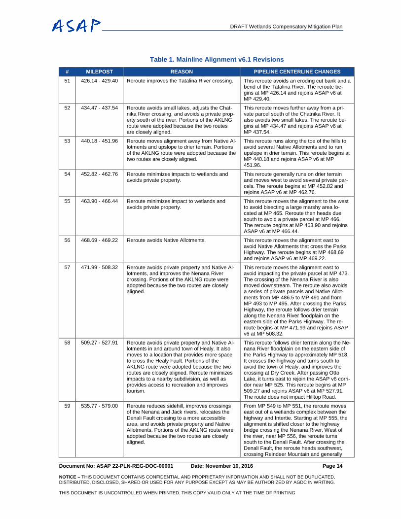
Table 1. Mainline Alignment v6.1 Revisions
# MILEPOST REASON PIPELINE CENTERLINE CHANGES 51 426.14 - 429.40 Reroute improves the Tatalina River crossing. This reroute avoids an eroding cut bank and a
bend of the Tatalina River. The reroute be-gins at MP 426.14 and rejoins ASAP v6 at MP 429.40.
52 434.47 - 437.54 Reroute avoids small lakes, adjusts the Chat-nika River crossing, and avoids a private prop-erty south of the river. Portions of the AKLNG route were adopted because the two routes are closely aligned.
This reroute moves further away from a pri-vate parcel south of the Chatnika River. It also avoids two small lakes. The reroute be-gins at MP 434.47 and rejoins ASAP v6 at MP 437.54.
53 440.18 - 451.96 Reroute moves alignment away from Native Al-lotments and upslope to drier terrain. Portions of the AKLNG route were adopted because the two routes are closely aligned.
This reroute runs along the toe of the hills to avoid several Native Allotments and to run upslope in drier terrain. This reroute begins at MP 440.18 and rejoins ASAP v6 at MP 451.96.
54 452.82 - 462.76 Reroute minimizes impacts to wetlands and avoids private property.
This reroute generally runs on drier terrain and moves west to avoid several private par-cels. The reroute begins at MP 452.82 and rejoins ASAP v6 at MP 462.76.
55 463.90 - 466.44 Reroute minimizes impact to wetlands and avoids private property.
This reroute moves the alignment to the west to avoid bisecting a large marshy area lo-cated at MP 465. Reroute then heads due south to avoid a private parcel at MP 466. The reroute begins at MP 463.90 and rejoins ASAP v6 at MP 466.44.
56 468.69 - 469.22 Reroute avoids Native Allotments. This reroute moves the alignment east to avoid Native Allotments that cross the Parks Highway. The reroute begins at MP 468.69 and rejoins ASAP v6 at MP 469.22.
57 471.99 - 508.32 Reroute avoids private property and Native Al-lotments, and improves the Nenana River crossing. Portions of the AKLNG route were adopted because the two routes are closely aligned.
This reroute moves the alignment east to avoid impacting the private parcel at MP 473. The crossing of the Nenana River is also moved downstream. The reroute also avoids a series of private parcels and Native Allot-ments from MP 486.5 to MP 491 and from MP 493 to MP 495. After crossing the Parks Highway, the reroute follows drier terrain along the Nenana River floodplain on the eastern side of the Parks Highway. The re-route begins at MP 471.99 and rejoins ASAP v6 at MP 508.32.
58 509.27 - 527.91 Reroute avoids private property and Native Al-lotments in and around town of Healy. It also moves to a location that provides more space to cross the Healy Fault. Portions of the AKLNG route were adopted because the two routes are closely aligned. Reroute minimizes impacts to a nearby subdivision, as well as provides access to recreation and improves tourism.
This reroute follows drier terrain along the Ne-nana River floodplain on the eastern side of the Parks Highway to approximately MP 518. It crosses the highway and turns south to avoid the town of Healy, and improves the crossing at Dry Creek. After passing Otto Lake, it turns east to rejoin the ASAP v6 corri-dor near MP 525. This reroute begins at MP 509.27 and rejoins ASAP v6 at MP 527.91. The route does not impact Hilltop Road.
59 535.77 - 579.00 Reroute reduces sidehill, improves crossings of the Nenana and Jack rivers, relocates the Denali Fault crossing to a more accessible area, and avoids private property and Native Allotments. Portions of the AKLNG route were adopted because the two routes are closely aligned.
From MP 549 to MP 551, the reroute moves east out of a wetlands complex between the highway and Intertie. Starting at MP 555, the alignment is shifted closer to the highway bridge crossing the Nenana River. West of the river, near MP 556, the reroute turns south to the Denali Fault. After crossing the Denali Fault, the reroute heads southwest, crossing Reindeer Mountain and generally
DRAFT Wetlands Compensatory Mitigation Plan
Document No: ASAP 22-PLN-REG-DOC-00001 Date: November 10, 2016 Page 15 NOTICE – THIS DOCUMENT CONTAINS CONFIDENTIAL AND PROPRIETARY INFORMATION AND SHALL NOT BE DUPLICATED, DISTRIBUTED, DISCLOSED, SHARED OR USED FOR ANY PURPOSE EXCEPT AS MAY BE AUTHORIZED BY AGDC IN WRITING. THIS DOCUMENT IS UNCONTROLLED WHEN PRINTED. THIS COPY VALID ONLY AT THE TIME OF PRINTING
Table 1. Mainline Alignment v6.1 Revisions
# MILEPOST REASON PIPELINE CENTERLINE CHANGES following the Intertie to bypass Cantwell. The reroute crosses the Jack River adjacent to the old highway bridge alignment south of Cant-well. The reroute heads west to a crossing of the Parks Highway and the AK RR near MP 567. After crossing the railroad, the reroute continues southwest avoiding the Summit air-strip and then reconnects at MP 579. The re-route begins at MP 535.77 and ends at MP 579.
60 579.82 - 580.78 Reroute improves Middle Fork Chulitna River crossing and avoids probable high-quality fish habitat.
This reroute moves the Middle Fork Chulitna River crossing upstream to avoid probable high-quality fish habitat. The reroute begins at MP 579.82 and rejoins ASAP v6 at MP 580.78.
61 582.14 - 600.11 Reroute refines several stream crossings, straightens the alignment, and moves onto drier terrain. Portions of the AKLNG route were adopted because the two routes are closely aligned.
The reroute begins at MP 582 and changes the AK RR and Parks Highway crossings, then heads south to a new crossing of the East Fork Chulitna River. From there it gener-ally follows the existing power lines from MP 584 to MP 590. Then it moves upslope, im-proving the stream crossing at Antimony Creek, Honolulu Creek, and Little Honolulu Creek. This reroute increases sidehill slopes between MP 590 and MP 597; however, it re-duces crossings of string bogs. This reroute begins at MP 582.14 and rejoins ASAP v6 at MP 600.11.
62 602.58 - 603.00 Reroute moves railroad crossing onto drier ground.
This reroute moves the railroad crossing south onto drier ground. The reroute begins at MP 602.58 and rejoins ASAP v6 at MP 603.00.
63 606.17 - 607.00 Reroute avoids having to remove a beaver dam and potentially resulting in large-scale im-pacts on upstream wetlands.
This reroute moves the road crossing about 1,000 feet north along the Parks Highway. Construction at the current site would remove a beaver dam and potentially have large-scale impacts on upstream wetlands. The re-route begins at MP 606.17 and rejoins ASAP v6 at MP 607.
64 609.55 - 610.49 Reroute improves stream crossing. The reroute moves the alignment off of a deeply incised channel to flatter, but wetter, terrain. This reroute begins at MP 609.55 and rejoins ASAP v6 at MP 610.49.
65 612.34 - 613.07 Reroute reduces impacts to wetlands. The reroute moves the alignment onto drier terrain and avoids a wetland at MP 612.9. This reroute begins at MP 612.34 and rejoins ASAP v6 at MP 613.07.
66 616.55 - 617.41 Reroute straightens out the alignment and moves it onto a dry ridgeline.
This reroute moves the alignment onto a ridgeline, out of wet areas along ASAP v6. This reroute begins at MP 616.55 and rejoins ASAP v6 at MP 617.41.
67 623.98 - 667.09 Reroute reduces visual impacts to the Veter-ans Memorial, moves to drier terrain, and im-proves stream and river crossings. It avoids probable high-value spawning habitat. Portions of the AKLNG route were adopted because the two routes are closely aligned.
This reroute reduces the visual impacts of cutting an ROW close to the highway oppo-site the Veterans Memorial. The Chulitna River crossing is shifted upstream to a nar-rower section. The southern end of the re-route generally straightens the alignment and stays off of sidehill areas, and avoids boggy
DRAFT Wetlands Compensatory Mitigation Plan
Document No: ASAP 22-PLN-REG-DOC-00001 Date: November 10, 2016 Page 16 NOTICE – THIS DOCUMENT CONTAINS CONFIDENTIAL AND PROPRIETARY INFORMATION AND SHALL NOT BE DUPLICATED, DISTRIBUTED, DISCLOSED, SHARED OR USED FOR ANY PURPOSE EXCEPT AS MAY BE AUTHORIZED BY AGDC IN WRITING. THIS DOCUMENT IS UNCONTROLLED WHEN PRINTED. THIS COPY VALID ONLY AT THE TIME OF PRINTING
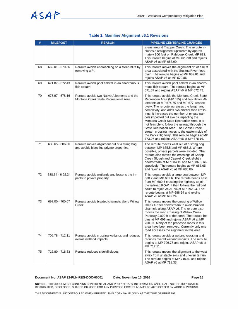
Table 1. Mainline Alignment v6.1 Revisions
# MILEPOST REASON PIPELINE CENTERLINE CHANGES areas around Trapper Creek. The reroute in-cludes a realignment upstream by approxi-mately 300 feet on Rabideux Creek MP 633. This reroute begins at MP 623.98 and rejoins ASAP v6 at MP 667.09.
68 669.01 - 670.86 Reroute avoids encroaching on a steep bluff by removing a PI.
This reroute moves the alignment off of a bluff area associated with the Susitna River flood-plain. The reroute begins at MP 669.01 and rejoins ASAP v6 at MP 670.86.
69 671.87 - 672.43 Reroute avoids pool habitat in an anadromous fish stream.
This reroute avoids pool habitat in an anadro-mous fish stream. The reroute begins at MP 671.87 and rejoins ASAP v6 at MP 672.43.
70 673.97 - 678.16 Reroute avoids two Native Allotments and the Montana Creek State Recreational Area.
This reroute avoids the Montana Creek State Recreation Area (MP 675) and two Native Al-lotments at MP 674.75 and MP 677, respec-tively. The reroute increases the length and complexity, and adds two arterial road cross-ings. It increases the number of private par-cels impacted but avoids impacting the Montana Creek State Recreation Area. It is not feasible to follow the railroad through the State Recreation Area. The Goose Creek stream crossing moves to the eastern side of the Parks Highway. This reroute begins at MP 673.97 and rejoins ASAP v6 at MP 678.16.
71 683.65 - 686.86 Reroute moves alignment out of a string bog and avoids bisecting private properties.
The reroute moves west out of a string bog between MP 685.5 and MP 686.2. Where possible, private parcels were avoided. The reroute also moves the crossings of Sheep Creek Slough and Caswell Creek slightly downstream at MP 684.15 and MP 686.3, re-spectively. The reroute begins at MP 683.65 and rejoins ASAP v6 at MP 686.86
72 688.64 - 6.92.24 Reroute avoids wetlands and lessens the im-pacts to private property.
This reroute avoids a large bog between MP 688.7 and MP 689.6. The reroute heads east from MP 689.6 crossing the highway to join the railroad ROW. It then follows the railroad south to rejoin ASAP v6 at MP 692.24. The reroute begins at MP 688.64 and rejoins ASAP v6 at MP 692.24.
73 698.00 - 700.07 Reroute avoids braided channels along Willow Creek.
This reroute moves the crossing of Willow Creek further downstream to avoid braided channels along ASAP v6. The reroute also moves the road crossing of Willow Creek Parkway 2,000 ft to the north. The reroute be-gins at MP 698 and rejoins ASAP v6 at MP 700.07. Many of the proposed roads in this area have been removed. Currently only one road accesses the alignment in this area.
74 706.78 - 712.11 Reroute avoids crossing wetlands and reduces overall wetland impacts.
This reroute avoids a wetland crossing and reduces overall wetland impacts. The reroute begins at MP 706.78 and rejoins ASAP v6 at MP 712.11.
75 716.80 - 718.33 Reroute reduces sidehill slopes. This reroute moves the alignment to the west away from unstable soils and uneven terrain. The reroute begins at MP 716.80 and rejoins ASAP v6 at MP 718.33.
DRAFT Wetlands Compensatory Mitigation Plan
Document No: ASAP 22-PLN-REG-DOC-00001 Date: November 10, 2016 Page 17 NOTICE – THIS DOCUMENT CONTAINS CONFIDENTIAL AND PROPRIETARY INFORMATION AND SHALL NOT BE DUPLICATED, DISTRIBUTED, DISCLOSED, SHARED OR USED FOR ANY PURPOSE EXCEPT AS MAY BE AUTHORIZED BY AGDC IN WRITING. THIS DOCUMENT IS UNCONTROLLED WHEN PRINTED. THIS COPY VALID ONLY AT THE TIME OF PRINTING
Table 1. Mainline Alignment v6.1 Revisions
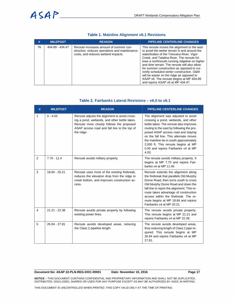
# MILEPOST REASON PIPELINE CENTERLINE CHANGES 76 404.89 - 434.47 Reroute increases amount of summer con-
struction, reduces operations and maintenance costs, and reduces wetland impacts.
This reroute moves the alignment to the east to avoid the wetter terrain in and around the waterbodies of the Tolovana River, Vigor Creek, and Tatalina River. The reroute fol-lows a north/south-running ridgeline on higher and drier terrain. The reroute will also allow for summer construction as opposed to cur-rently scheduled winter construction. O&M will be easier on the ridge as opposed to ASAP v6. The reroute begins at MP 404.89 and rejoins ASAP v6 at MP 434.47.
Table 2. Fairbanks Lateral Revisions – v6.0 to v6.1
# MILEPOST REASON PIPELINE CENTERLINE CHANGES
1 0 - 4.03 Reroute adjusts the alignment to avoid cross-ing a pond, wetlands, and other kettle lakes. Reroute more closely follows the proposed ASAP access road and fall line to the top of the ridge.
The alignment was adjusted to avoid crossing a pond, wetlands, and other kettle lakes. The reroute also improves routing to the east by following the pro-posed ASAP access road and staying on the fall line. This alternate moves the mainline tie-in south approximately 2,000 ft. This reroute begins at MP 0.00 and rejoins Fairbanks v4 at MP 4.03.
2 7.70 - 11.4 Reroute avoids military property. The reroute avoids military property. It begins at MP 7.70 and rejoins Fair-banks v4 at MP 11.40.
3 18.84 - 20.21 Reroute uses more of the existing firebreak, reduces the elevation drop from the ridge to creek bottom, and improves construction ac-cess.
Reroute extends the alignment along the firebreak that parallels Old Murphy Dome Road, then turns south to cross Old Murphy Dome Road and down the fall line to rejoin the alignment. This re-route takes advantage of construction access within the firebreak. The re-route begins at MP 18.84 and rejoins Fairbanks v4 at MP 20.21.
4 21.21 - 22.38 Reroute avoids private property by following existing power lines.
The reroute avoids private property. This reroute begins at MP 21.21 and rejoins Fairbanks v4 at MP 22.39.
5 26.94 - 27.81 Reroute avoids developed areas, reducing the Class 2 pipeline length.
The reroute avoids developed areas, thus reducing length of Class 2 pipe re-quired. This reroute begins at MP 26.94 and rejoins Fairbanks v4 at MP 27.81.
DRAFT Wetlands Compensatory Mitigation Plan
Document No: ASAP 22-PLN-REG-DOC-00001 Date: November 10, 2016 Page 18 NOTICE – THIS DOCUMENT CONTAINS CONFIDENTIAL AND PROPRIETARY INFORMATION AND SHALL NOT BE DUPLICATED, DISTRIBUTED, DISCLOSED, SHARED OR USED FOR ANY PURPOSE EXCEPT AS MAY BE AUTHORIZED BY AGDC IN WRITING. THIS DOCUMENT IS UNCONTROLLED WHEN PRINTED. THIS COPY VALID ONLY AT THE TIME OF PRINTING
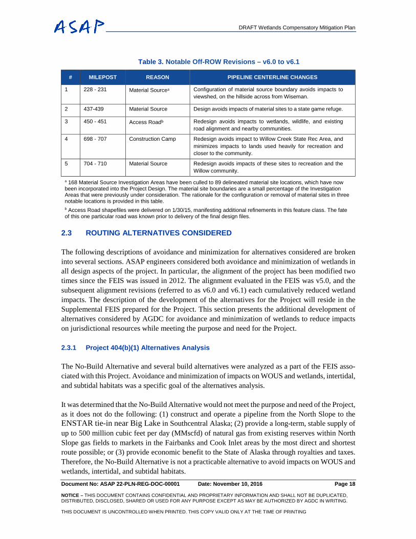
Table 3. Notable Off-ROW Revisions – v6.0 to v6.1
# MILEPOST REASON PIPELINE CENTERLINE CHANGES
1 228 - 231 Material Sourcea Configuration of material source boundary avoids impacts to viewshed, on the hillside across from Wiseman.
2 437-439 Material Source Design avoids impacts of material sites to a state game refuge.
3 450 - 451 Access Roadb Redesign avoids impacts to wetlands, wildlife, and existing road alignment and nearby communities.
4 698 - 707 Construction Camp Redesign avoids impact to Willow Creek State Rec Area, and minimizes impacts to lands used heavily for recreation and closer to the community.
5 704 - 710 Material Source Redesign avoids impacts of these sites to recreation and the Willow community.
a 168 Material Source Investigation Areas have been culled to 89 delineated material site locations, which have now been incorporated into the Project Design. The material site boundaries are a small percentage of the Investigation Areas that were previously under consideration. The rationale for the configuration or removal of material sites in three notable locations is provided in this table. b Access Road shapefiles were delivered on 1/30/15, manifesting additional refinements in this feature class. The fate of this one particular road was known prior to delivery of the final design files.
2.3 ROUTING ALTERNATIVES CONSIDERED
The following descriptions of avoidance and minimization for alternatives considered are broken into several sections. ASAP engineers considered both avoidance and minimization of wetlands in all design aspects of the project. In particular, the alignment of the project has been modified two times since the FEIS was issued in 2012. The alignment evaluated in the FEIS was v5.0, and the subsequent alignment revisions (referred to as v6.0 and v6.1) each cumulatively reduced wetland impacts. The description of the development of the alternatives for the Project will reside in the Supplemental FEIS prepared for the Project. This section presents the additional development of alternatives considered by AGDC for avoidance and minimization of wetlands to reduce impacts on jurisdictional resources while meeting the purpose and need for the Project.
2.3.1 Project 404(b)(1) Alternatives Analysis
The No-Build Alternative and several build alternatives were analyzed as a part of the FEIS asso-ciated with this Project. Avoidance and minimization of impacts on WOUS and wetlands, intertidal, and subtidal habitats was a specific goal of the alternatives analysis.
It was determined that the No-Build Alternative would not meet the purpose and need of the Project, as it does not do the following: (1) construct and operate a pipeline from the North Slope to the ENSTAR tie-in near Big Lake in Southcentral Alaska; (2) provide a long-term, stable supply of up to 500 million cubic feet per day (MMscfd) of natural gas from existing reserves within North Slope gas fields to markets in the Fairbanks and Cook Inlet areas by the most direct and shortest route possible; or (3) provide economic benefit to the State of Alaska through royalties and taxes. Therefore, the No-Build Alternative is not a practicable alternative to avoid impacts on WOUS and wetlands, intertidal, and subtidal habitats.
DRAFT Wetlands Compensatory Mitigation Plan
Document No: ASAP 22-PLN-REG-DOC-00001 Date: November 10, 2016 Page 19 NOTICE – THIS DOCUMENT CONTAINS CONFIDENTIAL AND PROPRIETARY INFORMATION AND SHALL NOT BE DUPLICATED, DISTRIBUTED, DISCLOSED, SHARED OR USED FOR ANY PURPOSE EXCEPT AS MAY BE AUTHORIZED BY AGDC IN WRITING. THIS DOCUMENT IS UNCONTROLLED WHEN PRINTED. THIS COPY VALID ONLY AT THE TIME OF PRINTING
Major route alternatives were discussed in the FEIS and formed the basis of the alternatives that will be described in the SEIS. The Richardson Highway was the major route alternative compared with the Parks Highway Route, which was chosen as the preferred alternative. The Richardson Highway Route would be longer by 92 miles (845 miles long versus 733 miles) and would cross a greater number of streams (515 versus 419) and two mountain ranges. As a result of the increased length, the Richardson Highway Route Alternative would impact 23 percent more wetland features (730 versus 593 features), 35 percent more wetland habitat (1,735 versus 1,288 wetland acres), and a greater number of wetland acres of each wetland type than the Parks Highway Route that was studied in the Alternatives Analysis conducted by the State of Alaska. The Parks Highway Alter-native was then modified into the proposed Project through ROW refinement and shortening by an additional 26 miles, resulting in further avoidance and minimization of WOUS impacts.
Route variations were also evaluated in the FEIS. These included the Fairbanks Route Variation, Alaska Intertie Route Variation, Denali National Park Route Variation, and several Alaska Railroad (ARR) Route Variations. Route variations were compared with the proposed Project to see if envi-ronmental impacts, including those to WOUS, would be reduced with the variation. The route var-iations are discussed later in this section.
Since completion of the FEIS project, changes have resulted in advancement of a pipeline that increased in diameter from 24 to 36 inches. The following discussion centers on the alternatives to be reconsidered in the SEIS and explains how, as an applicant for a 404 permit, the AGDC demon-strates that the proposed Project is the least environmentally damaging practicable alternative (LEDPA) for achieving the Project's purpose. The basis for the LEDPA determination is CFR Title 40, Section 230.10(a). No practicable alternative to the proposed Project exists that would have a less adverse impact on aquatic ecosystems and that does not have other significant adverse envi-ronmental consequences.
2.3.2 Alaska Intertie Route Variation
The Alaska Intertie Route Variation would include a route around the eastern side of Sugar Loaf Mountain, which was found to not be practicable for a variety of reasons, including rugged terrain, lack of road access, and significant engineering, construction, and maintenance challenges.
2.3.3 Denali National Park Route Variation
A revised 7.6 mile Denali National Park Route Variation is provided as an alternative to the 7.2 mile-long segment of the proposed Project between approximately MP 535.8 and 543. The Denali National Park Variation is described and evaluated in the ASAP Environmental Evaluation Docu-ment (EED) (AGDC 2016), and is displayed on the ASAP Interactive Webviewer at: http://asap-gas.agdc.us/interactivemap.html.
2.3.4 Alaska Railroad Route Variations
The following subsections explain route variations for the Alaska Railroad.
DRAFT Wetlands Compensatory Mitigation Plan
Document No: ASAP 22-PLN-REG-DOC-00001 Date: November 10, 2016 Page 20 NOTICE – THIS DOCUMENT CONTAINS CONFIDENTIAL AND PROPRIETARY INFORMATION AND SHALL NOT BE DUPLICATED, DISTRIBUTED, DISCLOSED, SHARED OR USED FOR ANY PURPOSE EXCEPT AS MAY BE AUTHORIZED BY AGDC IN WRITING. THIS DOCUMENT IS UNCONTROLLED WHEN PRINTED. THIS COPY VALID ONLY AT THE TIME OF PRINTING
2.3.5 Curry Rail Route Variation
Although the Curry Rail Route Variation would be 3.5 miles shorter than the proposed Project route segment it would replace, it would require new impacts on 594 more acres of land. The Curry Rail Route Variation would cross approximately 64 streams, as opposed to 39 stream crossings for the segment of the proposed Project route that it would replace. The Curry Rail Route Variation would not be road accessible, and therefore would require access from the Parks Highway at the northern or southern ends or from the ARR. Therefore, the Curry Rail Route Variation would present con-struction and maintenance access issues and would not reduce impacts on WOUS over the proposed Project route.
2.3.6 Port MacKenzie Rail Route Variation
The 33.1-mile Port MacKenzie Rail Route Variation would replace a 30.6-mile segment of the proposed Project route. A 21.8-mile segment of this route variation would impact approximately 160 acres of wetlands compared with approximately 135.7 acres of wetlands along the proposed Project route. The 21.8-mile route variation would cross several more waterbodies than proposed Project route (v6.1). Additional unquantified wetland impacts and stream crossings would occur within the remaining 11.3-mile segment of this route variation from Willow to near Houston. Based upon this comparison, collocating the proposed Project pipeline with the Port MacKenzie Rail Ex-tension Project would result in a 2.5-mile longer pipeline than v6.1, more wetland impacts, and a greater number of stream crossings than the segment of the proposed Project pipeline that would be replaced. Therefore, this proposed route variation would not result in greater avoidance of im-pacts.
2.4 ADDITIONAL AVOIDANCE
2.4.1 Ice Roads
Ice roads will be used in the Northern Ecoregion to avoid impacts associated with disturbing or filling wetlands. Approximately 23 miles of ice roads are planned to avoid wetlands impacts.
2.4.2 Ice Pads and Snow Packing
Ice pads and snow packing will be used during the process of trenching and burying the pipe in the Northern Ecoregion to avoid impacts associated with disturbing or filling wetlands. The ice or snow surface will allow heavy equipment to drive over the tundra to perform construction while only having a 5 ft wide impact.
2.4.3 Preferential Use of Uplands or Previously Disturbed Areas
AGDC has preferentially sited larger facilities, such as camps, pipe storage yards, and O&M facil-ities in previously disturbed areas, as noted in detail in the ASAP Environmental Evaluation Doc-ument (EED) (AGDC 2016). AGDC has also opted to use existing access roads and material sites
DRAFT Wetlands Compensatory Mitigation Plan
Document No: ASAP 22-PLN-REG-DOC-00001 Date: November 10, 2016 Page 21 NOTICE – THIS DOCUMENT CONTAINS CONFIDENTIAL AND PROPRIETARY INFORMATION AND SHALL NOT BE DUPLICATED, DISTRIBUTED, DISCLOSED, SHARED OR USED FOR ANY PURPOSE EXCEPT AS MAY BE AUTHORIZED BY AGDC IN WRITING. THIS DOCUMENT IS UNCONTROLLED WHEN PRINTED. THIS COPY VALID ONLY AT THE TIME OF PRINTING
wherever practicable (AGDC 2016) to minimize disturbance to new wetlands. The project intends to use disturbed areas to the greatest extent practicable. Materials sites preferentially targeted dis-turbed areas and existing site use or expansion were possible.
Block valves would be located in non-WOUS locations to avoid impacts where the opportunity exists. As part of the design optimization, these valves are now included in the mainline footprint calculation versus being calculated as a separate fill component.
Limits of clearing, grubbing, and grading would be adjusted where feasible to avoid affecting WOUS habitats. Where clearing in WOUS could be avoided, limits to avoid impacts would be shown in the construction drawings and marked in the field. Excavated soils would be temporarily sidecast into the temporary construction easement. Upland locations would be used when available to avoid temporary impacts on WOUS. The number of miles of pipeline and lateral that would be suitable for upland sidecasting would be determined during later design stages. Excess spoil ma-terial, including vegetation, trees, and roots from clearings will be removed and placed in upland areas for permanent disposal. New material sites also preferentially targeted upland areas.
2.4.4 Open Water Avoidance
Waterbody crossings would avoid WOUS impacts by using trenchless technology such as HDD and aerial-crossing structures. WOUS impacts would be avoided at seven waterbodies via trench-less technology such as the HDD method. Impacts on WOUS would be avoided at 24 new or ex-isting bridges, including access roads. The pipeline would use aerial crossings at the Putuligayuk River near MP 3.1, the Nenana River near MP 530.9, Lynx Creek at MP 536.7, the Nenana River near MP 558.6, the Susitna River at MP 673.5, and Montana Creek at MP 680.7.
Where ponds are crossed in winter (e.g., the North Slope), construction will occur using an isolated open-cut method and will be treated similar to trenching through a winter stream. ASAP will have a 5-foot-wide temporary impact to the pond. Where ponds are crossed in summer, ASAP will bore under them, similar to a crossing of TAPS. These sort of borings are shorter, shallower, and simpler than HDD crossings and do not require the same sort of HDD entry or exit pads. Corrections have been made to the footprint so that all pond crossings are treated consistently.
2.4.5 Material Sites (Borrow)
Materials sites (borrow) investigations avoided impacts significantly throughout the design pro-cess. Pipeline and ancillary facility and access road refinements have reduced the amount of fill material required and, in turn, the number of related material sites and access roads needed. Along with reduced fill requirements, desktop data analysis and field studies further reduced the impacts of material site development on wetlands. Further refinements were made to the numbers of sites needed, siting to limit haul distances, avoiding impacts on wetlands and established waterbodies, avoiding groundwater where possible, and reducing the overall number of quarry sites versus bor-row sites. Available wetlands delineation data were used to adjust the boundaries of planned mate-rial sites to avoid wetland impacts, reflect the true size of development footprints, and reduce the
DRAFT Wetlands Compensatory Mitigation Plan
Document No: ASAP 22-PLN-REG-DOC-00001 Date: November 10, 2016 Page 22 NOTICE – THIS DOCUMENT CONTAINS CONFIDENTIAL AND PROPRIETARY INFORMATION AND SHALL NOT BE DUPLICATED, DISTRIBUTED, DISCLOSED, SHARED OR USED FOR ANY PURPOSE EXCEPT AS MAY BE AUTHORIZED BY AGDC IN WRITING. THIS DOCUMENT IS UNCONTROLLED WHEN PRINTED. THIS COPY VALID ONLY AT THE TIME OF PRINTING
footprints to what is needed. A critical part of this process was a 2-day workshop to review potential material sites and provide the design and environmental teams an opportunity to discuss and un-derstand ways to improve the material locations.
The number of material sites required has been reduced significantly throughout the planning pro-cess. The design team initially identified 168 potential source sites, and has since reduced the num-ber to 89 potential material source sites. Refinements are ongoing, and further reductions are possible. Material sites would occupy approximately 5,252 acres (1,763 acres of wetlands and 3,489 acres of uplands).
Using existing material source sites, expanding existing sites over developing new ones, and using existing roads for access are all preferred. New sites would avoid wetlands where practicable, and access roads associated with these sites would be routed to avoid hauling material over difficult wetland or riverine terrains. Proximity to alignment also would reduce access road length.
2.4.6 Access Roads
Access roads have been designed to avoid WOUS where possible. The access roads would be lo-cated based on several factors, including access road slopes, existing roads, and delineated and wetlands. The grades to the material sites and pipeline cannot exceed 6 percent for any sustained period. After accounting for grade, the roadway design team used the ArcReader system to avoid high-value wetlands as much as possible. Then through the wetlands-viewing platform, field stud-ies, and numerous revisions, access roads were refined to reduce the number, widths, and fill depths of access roads. Access roads were eliminated by identifying and removing duplicate roads, using only those access roads required, changing access road spacing along the mainline from 5 to 10 miles, reviewing each access road for need, and reviewing width and locations of all existing roads in the corridor. Table 4 shows the reduction in roadway length and number from an earlier version of the project considered (v6, December 2013) and the current version of the Project (v6.1, Febru-ary 2015).
Table 4. Reduction in Length and Number of Access Roads from v6.0 to v6.1
CATEGORY TOTAL MILEAGE NUMBER OF ROADS
v6.0 v6.1 CHANGE v6.0 v6.1 CHANGE
New Roads 301.8 174.4 -127.4 397 298 -99
Temporary Ice Roads 22.6 22.9 +0.3 24 23 -1
2.4.7 Collocation of Facilities
Several facilities will be collocated to further avoid impacts to wetlands. For instance, camps and pipe storage yards will be collocated at times to reduce the number of access roads required and associated disturbance.
DRAFT Wetlands Compensatory Mitigation Plan
Document No: ASAP 22-PLN-REG-DOC-00001 Date: November 10, 2016 Page 23 NOTICE – THIS DOCUMENT CONTAINS CONFIDENTIAL AND PROPRIETARY INFORMATION AND SHALL NOT BE DUPLICATED, DISTRIBUTED, DISCLOSED, SHARED OR USED FOR ANY PURPOSE EXCEPT AS MAY BE AUTHORIZED BY AGDC IN WRITING. THIS DOCUMENT IS UNCONTROLLED WHEN PRINTED. THIS COPY VALID ONLY AT THE TIME OF PRINTING
2.5 ADDITIONAL MINIMIZATION
In some areas, project impacts to wetlands will be temporary, minimizing impacts to wetlands. Tem-porary impacts will not require compensatory mitigation as there will be no long-term impacts to wetlands in these areas. Clearing or trenching may be considered temporary impact if the de-graded wetland plant community is able to revegetate promptly after construction and hydrologic function is not impacted, or if it returns. For instance, streams impacted by the Project will be tem-porary in nature.
Wetland crossings with soft sub-soils completed during the summer may be constructed using a push-pull technique, which requires excavation of the ditch from temporary mats (typically wood mats with approximate dimensions of 20 ft x 4 ft by 12 inches). Heavy equipment working on mats may use low ground-bearing equipment to reduce the wetland vegetation and soil disturbance. Ditch spoil can be placed on either side of the ditch on the mats because the pipeline will be strung and welded outside the wetland, and the pipe string will be pushed and pulled into place. Backfill of the pipeline is accomplished in a similar manner using excavators on mats. Placement of clean mats for construction access through a wetland is a protective measure that may be used in some areas and will not result in wetland degradation. In some areas, excavated material temporarily side-cast into wetlands will be underlain with geotextile, ice pads, or similar material to allow removal to the maximum extent practicable with the least damage to the underlying wetland vegetation.
2.5.1 Temporary Facilities
Temporary workspaces (TWs) and false rights-of-way (ROWs) would be used during construction to minimize impacts to wetlands. These facilities would accommodate activities such as walking, laying down materials, clearing vegetation above the root, and use of vehicles with low-pressure tires or tracks to minimize permanent impacts through wetlands through only a temporary (short-term) impact without the need for fill.
2.5.2 Revegetation
The ASAP Project design will incorporate revegetation procedures to be implemented immediately after construction to stabilize areas and prevent erosion, as well as to help regain partial hydrologic functions. The Alaska Department of Natural Resources - Plant Materials Center (ADNR - PMC) has worked with AGDC to produce a revegetation plan based around the different ecoregions of the Project. Specific procedures and recommended seed types and seed mixes are provided in this plan, attached to the ASAP EED (AGDC 2016).
Revegetation of impacted sites will begin as soon as onsite conditions allow, and in the same grow-ing season as the disturbance unless conditions warrant additional time. The landowner, through the right-of-way agreements, will stipulate the approved method of revegetation and restoration upon project completion.
DRAFT Wetlands Compensatory Mitigation Plan
Document No: ASAP 22-PLN-REG-DOC-00001 Date: November 10, 2016 Page 24 NOTICE – THIS DOCUMENT CONTAINS CONFIDENTIAL AND PROPRIETARY INFORMATION AND SHALL NOT BE DUPLICATED, DISTRIBUTED, DISCLOSED, SHARED OR USED FOR ANY PURPOSE EXCEPT AS MAY BE AUTHORIZED BY AGDC IN WRITING. THIS DOCUMENT IS UNCONTROLLED WHEN PRINTED. THIS COPY VALID ONLY AT THE TIME OF PRINTING
2.6 WATER CROSSINGS AND WATER MANAGEMENT
Identifying crossing modes for streams and waterbodies intercepted by the ASAP mainline and access roads has been a critical component of minimizing impacts. A major hydrologic design pro-cess was conducted to avoid and minimize crossing impacts and it consisted of field surveys, stream classification/characterization, a fish and wildlife habitat sensitivity analysis, and design of cross-ing techniques to minimize impacts.
All stream open cut or isolated open cut stream crossings would result in only a temporary impact to WOUS, with no permanent impacts expected. The Project would cross 245 waterbodies by iso-lated open-cut crossing methods (i.e., dam and pump or flume crossings) and 170 (includes multiple crossings of a waterbody) by open-cut methods. All workpads would be placed at least 50 ft from WOUS and waterbodies and within the temporary construction easement. No drilling materials would be sidecast into a WOUS. Streambank revegetation techniques will be defined for the stream cross cuts to help reduce erosion and to provide for restoration success. Revegetation techniques for streambanks are included in Streambank Revegetation and Protection: A Guide for Alaska (ADF&G 2005). Natural drainage patterns will be maintained using appropriate ditching, culverts, and other measures to prevent ponding or drying. Pipeline installation in wetlands will include measures to eliminate the potential for water flow within the trench (e.g., ditch plugs). All culverts in fish-bearing waters must be installed in accordance with a valid Alaska Department of Fish & Game Fish Habitat permit. Best Management Practices would be consulted to specify the proper use of culverts for surface flow.
Fish and wildlife habitat sensitivity analysis was conducted following 2014 data collection efforts. Field data were spatially analyzed in GIS and overlain upon various spatial data sets, including National Wetlands Inventory (NWI), Anadromous Waters Catalog, Alaska Freshwater Fish Inven-tory, National Hydrography Database (NHD), and aerial imagery. This effort generated detailed recommendations identifying the LEDPAs to current engineering plans. Where feasible, alignment route alternatives were identified where certain waterway crossings could be avoided entirely. In situations where complete avoidance was not possible or feasible, proximal crossing locations were identified where environmental impacts associated with in-stream construction efforts would be minimized. Where the alignment could not be adjusted, optimal construction seasons and modes to minimize impacts were identified. Table 5 lists some of the efforts associated with fish and aquatic habitat impact avoidance and minimization.
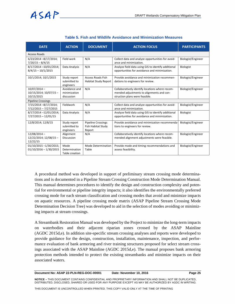
DRAFT Wetlands Compensatory Mitigation Plan
Document No: ASAP 22-PLN-REG-DOC-00001 Date: November 10, 2016 Page 25 NOTICE – THIS DOCUMENT CONTAINS CONFIDENTIAL AND PROPRIETARY INFORMATION AND SHALL NOT BE DUPLICATED, DISTRIBUTED, DISCLOSED, SHARED OR USED FOR ANY PURPOSE EXCEPT AS MAY BE AUTHORIZED BY AGDC IN WRITING. THIS DOCUMENT IS UNCONTROLLED WHEN PRINTED. THIS COPY VALID ONLY AT THE TIME OF PRINTING
Table 5. Fish and Wildlife Avoidance and Minimization Measures
DATE ACTION DOCUMENT ACTION FOCUS PARTICIPANTS
Access Roads 6/23/2014 –8/17/2014; 7/20/15 – 8/4/15
Field work N/A Collect data and analyze opportunities for avoid-ance and minimization.
Biologist/Engineer
8/17/2014 –10/01/2014; 8/4/15 – 10/1/2015
Data Analysis N/A Analyze field data using GIS to identify additional opportunities for avoidance and minimization.
Biologist
10/1/2014; 10/1/2015 Study report submitted to engineers
Access Roads Fish Habitat Study Report
Provide avoidance and minimization recommen-dations to engineers for review.
Biologist/Engineer
10/07/2014 –10/15/2014; 10/07/15 – 10/15/2015
Avoidance and minimization discussion
N/A Collaboratively identify locations where recom-mended adjustments to alignments and con-struction plans were feasible.
Biologist/Engineer
Pipeline Crossings 7/15/2014 –8/17/2014; 7/12/2015 – 7/27/2015
Fieldwork N/A Collect data and analyze opportunities for avoid-ance and minimization.
Biologist/Engineer
8/17/2014 –12/01/2014; 7/27/2015 – 12/01/15
Data Analysis N/A Analyze field data using GIS to identify additional opportunities for avoidance and minimization.
Biologist
12/8/2014; 12/8/15 Study report submitted to engineers
Pipeline Crossings Fish Habitat Study Report
Provide avoidance and minimization recommenda-tions to engineers for review.
Biologist/Engineer
12/08/2014 –12/22/2014; 12/08/15 – 12/22/15
Alignment Discussion
N/A Collaboratively identify locations where recom-mended alignment adjustments were feasible.
Biologist/Engineer
01/10/2015 –1/30/2015; 01/10/2016 – 1/30/2015
Mode Determination Table creation
Mode Determination Table
Provide mode and timing recommendations and assess feasibility.
Biologist/Engineer
A procedural method was developed in support of preliminary stream crossing mode determina-tions and is documented in a Pipeline Stream Crossing Construction Mode Determination Manual. This manual determines procedures to identify the design and construction complexity and poten-tial for environmental or pipeline integrity impacts; it also identifies the environmentally preferred crossing mode for each stream classification and crossing modes that avoid and minimize impacts on aquatic resources. A pipeline crossing mode matrix (ASAP Pipeline Stream Crossing Mode Determination Decision Tree) was developed to aid in the selection of modes avoiding or minimiz-ing impacts at stream crossings.
A Streambank Restoration Manual was developed by the Project to minimize the long-term impacts on waterbodies and their adjacent riparian zones crossed by the ASAP Mainline (AGDC 2015d,e). In addition site-specific stream crossing analyses and reports were developed to provide guidance for the design, construction, installation, maintenance, inspection, and perfor-mance evaluation of bank armoring and river training structures proposed for select stream cross-ings associated with the ASAP Mainline (AGDC 2015d,e). The manual proposes bank armoring protection methods intended to protect the existing streambanks and minimize impacts on their associated waters.
DRAFT Wetlands Compensatory Mitigation Plan
Document No: ASAP 22-PLN-REG-DOC-00001 Date: November 10, 2016 Page 26 NOTICE – THIS DOCUMENT CONTAINS CONFIDENTIAL AND PROPRIETARY INFORMATION AND SHALL NOT BE DUPLICATED, DISTRIBUTED, DISCLOSED, SHARED OR USED FOR ANY PURPOSE EXCEPT AS MAY BE AUTHORIZED BY AGDC IN WRITING. THIS DOCUMENT IS UNCONTROLLED WHEN PRINTED. THIS COPY VALID ONLY AT THE TIME OF PRINTING
For all pipeline stream crossings, AGDC will continue its comprehensive permit strategy to avoid and minimize fill and armor below ordinary high water. The final streambank restoration plan for each stream will be contingent on the streambed and stream bank composition, stream velocity, stream depth, and the crossing mode for each site. AGDC will investigate the use of bioengineered bank restoration and stabilization to include tree revetments, root wads, coir rolls, and coir mat lifts as appropriate and practicable.
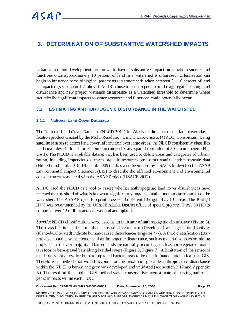
DRAFT Wetlands Compensatory Mitigation Plan
Document No: ASAP 22-PLN-REG-DOC-00001 Date: November 10, 2016 Page 27 NOTICE – THIS DOCUMENT CONTAINS CONFIDENTIAL AND PROPRIETARY INFORMATION AND SHALL NOT BE DUPLICATED, DISTRIBUTED, DISCLOSED, SHARED OR USED FOR ANY PURPOSE EXCEPT AS MAY BE AUTHORIZED BY AGDC IN WRITING. THIS DOCUMENT IS UNCONTROLLED WHEN PRINTED. THIS COPY VALID ONLY AT THE TIME OF PRINTING
3. DETERMINATION OF SUBSTANTIVE WATERSHED IMPACTS
Urbanization and development are known to have a substantive impact on aquatic resources and functions once approximately 10 percent of land in a watershed is urbanized. Urbanization can begin to influence some biological parameters in watersheds when between 5 – 10 percent of land is impacted (see section 1.2, above). AGDC chose to use 7.5 percent of the aggregate existing land disturbance and new project wetlands disturbance as a watershed threshold to determine where statistically significant impacts to water resources and functions could potentially occur.
3.1 ESTIMATING ANTHORPOGENIC DISTURBANCE IN THE WATERSHED
3.1.1 National Land Cover Database
The National Land Cover Database (NLCD 2011) for Alaska is the most recent land cover classi-fication product created by the Multi-Resolution Land Characteristics (MRLC) Consortium. Using satellite sensors to detect land cover information over large areas, the NLCD consistently classifies land cover descriptions into 16 common categories at a spatial resolution of 30 square meters (Fig-ure 3). The NLCD is a reliable dataset that has been used to define areas and categories of urbani-zation, including impervious surfaces, aquatic resources, and other spatial landscape-scale data (Hilderbrand et al. 2010; Utz et al. 2009). It has also been used by USACE to develop the ASAP Environmental Impact Statement (EIS) to describe the affected environment and environmental consequences associated with the ASAP Project (USACE 2012). AGDC used the NLCD as a tool to assess whether anthropogenic land cover disturbances have reached the threshold of what is known to significantly impact aquatic functions or resources of the watershed. The ASAP Project footprint crosses 60 different 10-digit (HUC10) areas. The 10-digit HUC was recommended by the USACE Alaska District office of special projects. These 60 HUCs comprise over 12 million acres of wetland and upland. Specific NLCD classifications were used as an indicator of anthropogenic disturbance (Figure 3). The classification codes for urban or rural development (Developed) and agricultural activity (Planted/Cultivated) indicate human-caused disturbances (Figures 4-7). A third classification (Bar-ren) also contains some elements of anthropogenic disturbance, such as material sources or mining projects, but the vast majority of barren lands are naturally occurring, such as non-vegetated moun-tain tops or bare gravel bars along braided rivers (Figure 3, Figure 7). A limitation of the sensor is that it does not allow for human-impacted barren areas to be discriminated automatically in GIS. Therefore, a method that would account for the maximum possible anthropogenic disturbance within the NLCD’s barren category was developed and validated (see section 3.12 and Appendix A). The result of this applied GIS method was a conservative overestimate of existing anthropo-genic impacts within each HUC.
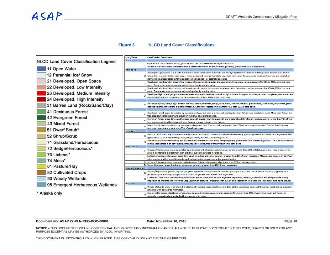
DRAFT Wetlands Compensatory Mitigation Plan
Document No: ASAP 22-PLN-REG-DOC-00001 Date: November 10, 2016 Page 28 NOTICE – THIS DOCUMENT CONTAINS CONFIDENTIAL AND PROPRIETARY INFORMATION AND SHALL NOT BE DUPLICATED, DISTRIBUTED, DISCLOSED, SHARED OR USED FOR ANY PURPOSE EXCEPT AS MAY BE AUTHORIZED BY AGDC IN WRITING. THIS DOCUMENT IS UNCONTROLLED WHEN PRINTED. THIS COPY VALID ONLY AT THE TIME OF PRINTING
Figure 3. NLCD Land Cover Classifications
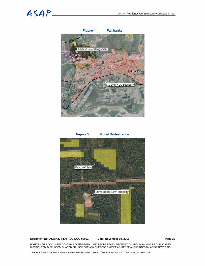
DRAFT Wetlands Compensatory Mitigation Plan
Document No: ASAP 22-PLN-REG-DOC-00001 Date: November 10, 2016 Page 29
NOTICE – THIS DOCUMENT CONTAINS CONFIDENTIAL AND PROPRIETARY INFORMATION AND SHALL NOT BE DUPLICATED, DISTRIBUTED, DISCLOSED, SHARED OR USED FOR ANY PURPOSE EXCEPT AS MAY BE AUTHORIZED BY AGDC IN WRITING. THIS DOCUMENT IS UNCONTROLLED WHEN PRINTED. THIS COPY VALID ONLY AT THE TIME OF PRINTING
Figure 4. Fairbanks
Figure 5. Rural Disturbance
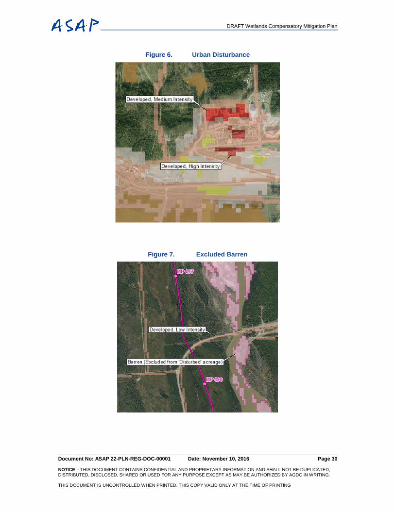
DRAFT Wetlands Compensatory Mitigation Plan
Document No: ASAP 22-PLN-REG-DOC-00001 Date: November 10, 2016 Page 30
NOTICE – THIS DOCUMENT CONTAINS CONFIDENTIAL AND PROPRIETARY INFORMATION AND SHALL NOT BE DUPLICATED, DISTRIBUTED, DISCLOSED, SHARED OR USED FOR ANY PURPOSE EXCEPT AS MAY BE AUTHORIZED BY AGDC IN WRITING. THIS DOCUMENT IS UNCONTROLLED WHEN PRINTED. THIS COPY VALID ONLY AT THE TIME OF PRINTING
Figure 6. Urban Disturbance
Figure 7. Excluded Barren
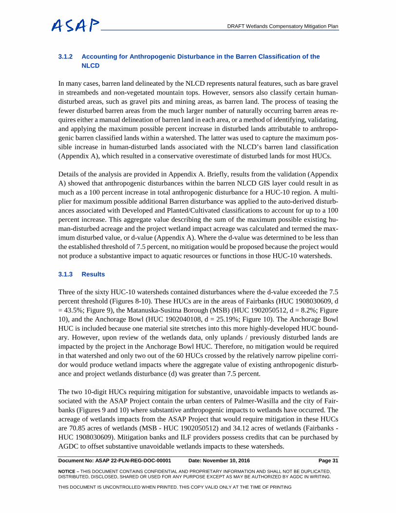
DRAFT Wetlands Compensatory Mitigation Plan
Document No: ASAP 22-PLN-REG-DOC-00001 Date: November 10, 2016 Page 31 NOTICE – THIS DOCUMENT CONTAINS CONFIDENTIAL AND PROPRIETARY INFORMATION AND SHALL NOT BE DUPLICATED, DISTRIBUTED, DISCLOSED, SHARED OR USED FOR ANY PURPOSE EXCEPT AS MAY BE AUTHORIZED BY AGDC IN WRITING. THIS DOCUMENT IS UNCONTROLLED WHEN PRINTED. THIS COPY VALID ONLY AT THE TIME OF PRINTING
3.1.2 Accounting for Anthropogenic Disturbance in the Barren Classification of the NLCD
In many cases, barren land delineated by the NLCD represents natural features, such as bare gravel in streambeds and non-vegetated mountain tops. However, sensors also classify certain human-disturbed areas, such as gravel pits and mining areas, as barren land. The process of teasing the fewer disturbed barren areas from the much larger number of naturally occurring barren areas re-quires either a manual delineation of barren land in each area, or a method of identifying, validating, and applying the maximum possible percent increase in disturbed lands attributable to anthropo-genic barren classified lands within a watershed. The latter was used to capture the maximum pos-sible increase in human-disturbed lands associated with the NLCD’s barren land classification (Appendix A), which resulted in a conservative overestimate of disturbed lands for most HUCs. Details of the analysis are provided in Appendix A. Briefly, results from the validation (Appendix A) showed that anthropogenic disturbances within the barren NLCD GIS layer could result in as much as a 100 percent increase in total anthropogenic disturbance for a HUC-10 region. A multi-plier for maximum possible additional Barren disturbance was applied to the auto-derived disturb-ances associated with Developed and Planted/Cultivated classifications to account for up to a 100 percent increase. This aggregate value describing the sum of the maximum possible existing hu-man-disturbed acreage and the project wetland impact acreage was calculated and termed the max-imum disturbed value, or d-value (Appendix A). Where the d-value was determined to be less than the established threshold of 7.5 percent, no mitigation would be proposed because the project would not produce a substantive impact to aquatic resources or functions in those HUC-10 watersheds. 3.1.3 Results
Three of the sixty HUC-10 watersheds contained disturbances where the d-value exceeded the 7.5 percent threshold (Figures 8-10). These HUCs are in the areas of Fairbanks (HUC 1908030609, d = 43.5%; Figure 9), the Matanuska-Susitna Borough (MSB) (HUC 1902050512, d = 8.2%; Figure 10), and the Anchorage Bowl (HUC 1902040108, d = 25.19%; Figure 10). The Anchorage Bowl HUC is included because one material site stretches into this more highly-developed HUC bound-ary. However, upon review of the wetlands data, only uplands / previously disturbed lands are impacted by the project in the Anchorage Bowl HUC. Therefore, no mitigation would be required in that watershed and only two out of the 60 HUCs crossed by the relatively narrow pipeline corri-dor would produce wetland impacts where the aggregate value of existing anthropogenic disturb-ance and project wetlands disturbance (d) was greater than 7.5 percent. The two 10-digit HUCs requiring mitigation for substantive, unavoidable impacts to wetlands as-sociated with the ASAP Project contain the urban centers of Palmer-Wasilla and the city of Fair-banks (Figures 9 and 10) where substantive anthropogenic impacts to wetlands have occurred. The acreage of wetlands impacts from the ASAP Project that would require mitigation in these HUCs are 70.85 acres of wetlands (MSB - HUC 1902050512) and 34.12 acres of wetlands (Fairbanks - HUC 1908030609). Mitigation banks and ILF providers possess credits that can be purchased by AGDC to offset substantive unavoidable wetlands impacts to these watersheds.
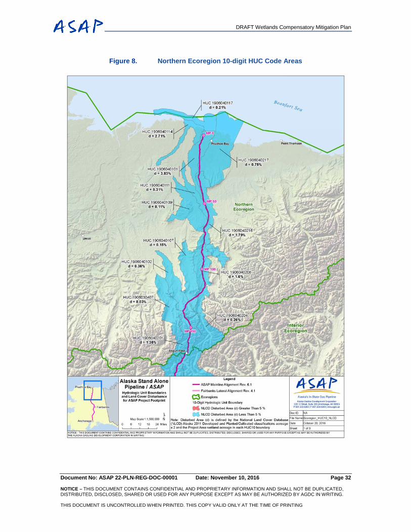
DRAFT Wetlands Compensatory Mitigation Plan
Document No: ASAP 22-PLN-REG-DOC-00001 Date: November 10, 2016 Page 32
NOTICE – THIS DOCUMENT CONTAINS CONFIDENTIAL AND PROPRIETARY INFORMATION AND SHALL NOT BE DUPLICATED, DISTRIBUTED, DISCLOSED, SHARED OR USED FOR ANY PURPOSE EXCEPT AS MAY BE AUTHORIZED BY AGDC IN WRITING. THIS DOCUMENT IS UNCONTROLLED WHEN PRINTED. THIS COPY VALID ONLY AT THE TIME OF PRINTING
Figure 8. Northern Ecoregion 10-digit HUC Code Areas
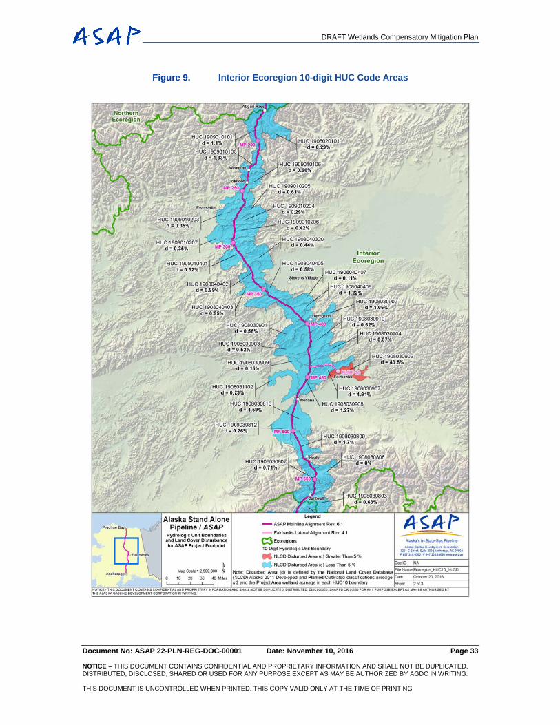
DRAFT Wetlands Compensatory Mitigation Plan
Document No: ASAP 22-PLN-REG-DOC-00001 Date: November 10, 2016 Page 33
NOTICE – THIS DOCUMENT CONTAINS CONFIDENTIAL AND PROPRIETARY INFORMATION AND SHALL NOT BE DUPLICATED, DISTRIBUTED, DISCLOSED, SHARED OR USED FOR ANY PURPOSE EXCEPT AS MAY BE AUTHORIZED BY AGDC IN WRITING. THIS DOCUMENT IS UNCONTROLLED WHEN PRINTED. THIS COPY VALID ONLY AT THE TIME OF PRINTING
Figure 9. Interior Ecoregion 10-digit HUC Code Areas
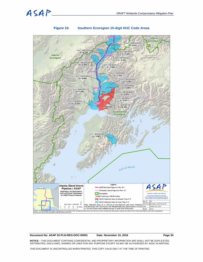
DRAFT Wetlands Compensatory Mitigation Plan
Document No: ASAP 22-PLN-REG-DOC-00001 Date: November 10, 2016 Page 34
NOTICE – THIS DOCUMENT CONTAINS CONFIDENTIAL AND PROPRIETARY INFORMATION AND SHALL NOT BE DUPLICATED, DISTRIBUTED, DISCLOSED, SHARED OR USED FOR ANY PURPOSE EXCEPT AS MAY BE AUTHORIZED BY AGDC IN WRITING. THIS DOCUMENT IS UNCONTROLLED WHEN PRINTED. THIS COPY VALID ONLY AT THE TIME OF PRINTING
Figure 10. Southern Ecoregion 10-digit HUC Code Areas
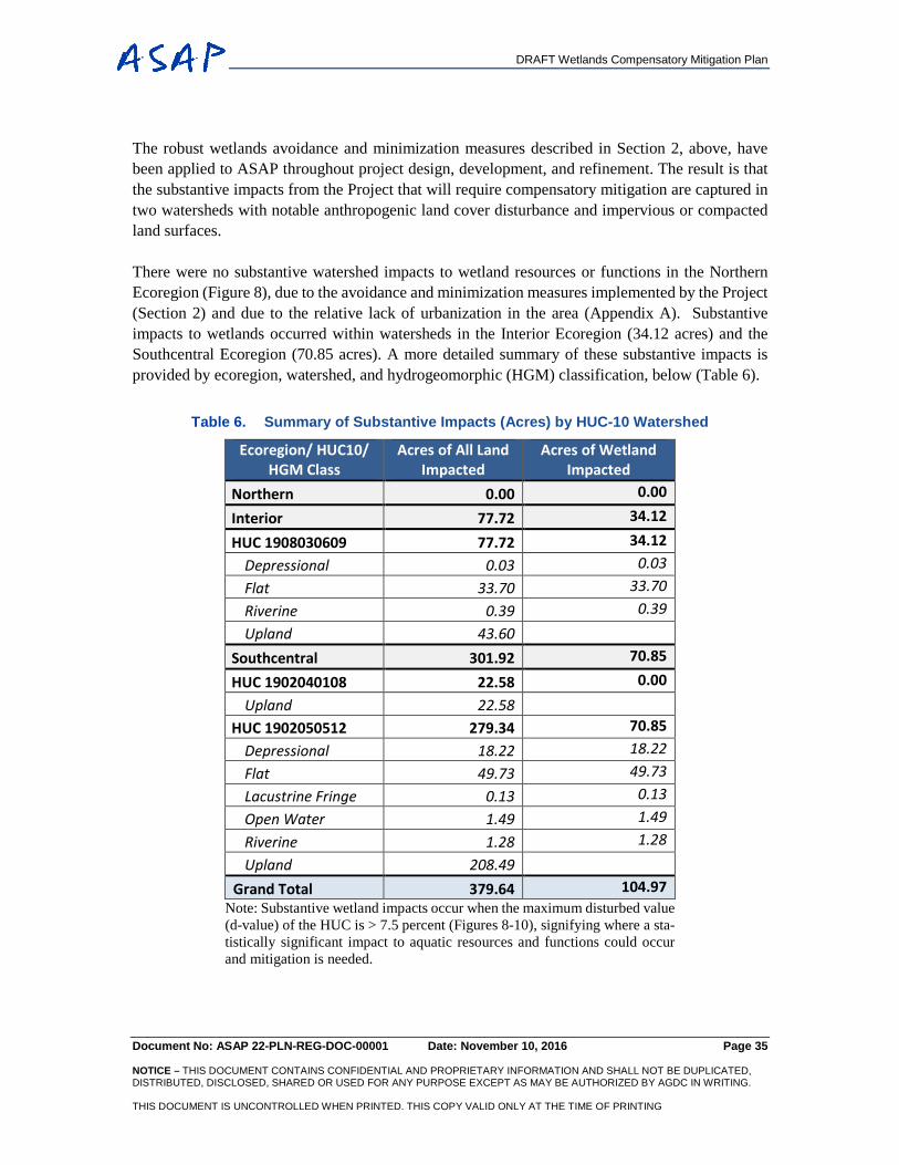
DRAFT Wetlands Compensatory Mitigation Plan
Document No: ASAP 22-PLN-REG-DOC-00001 Date: November 10, 2016 Page 35 NOTICE – THIS DOCUMENT CONTAINS CONFIDENTIAL AND PROPRIETARY INFORMATION AND SHALL NOT BE DUPLICATED, DISTRIBUTED, DISCLOSED, SHARED OR USED FOR ANY PURPOSE EXCEPT AS MAY BE AUTHORIZED BY AGDC IN WRITING. THIS DOCUMENT IS UNCONTROLLED WHEN PRINTED. THIS COPY VALID ONLY AT THE TIME OF PRINTING
The robust wetlands avoidance and minimization measures described in Section 2, above, have been applied to ASAP throughout project design, development, and refinement. The result is that the substantive impacts from the Project that will require compensatory mitigation are captured in two watersheds with notable anthropogenic land cover disturbance and impervious or compacted land surfaces. There were no substantive watershed impacts to wetland resources or functions in the Northern Ecoregion (Figure 8), due to the avoidance and minimization measures implemented by the Project (Section 2) and due to the relative lack of urbanization in the area (Appendix A). Substantive impacts to wetlands occurred within watersheds in the Interior Ecoregion (34.12 acres) and the Southcentral Ecoregion (70.85 acres). A more detailed summary of these substantive impacts is provided by ecoregion, watershed, and hydrogeomorphic (HGM) classification, below (Table 6).
Table 6. Summary of Substantive Impacts (Acres) by HUC-10 Watershed
Ecoregion/ HUC10/ HGM Class
Acres of All Land Impacted
Acres of Wetland Impacted
Northern 0.00 0.00
Interior 77.72 34.12
HUC 1908030609 77.72 34.12 Depressional 0.03 0.03 Flat 33.70 33.70 Riverine 0.39 0.39 Upland 43.60
Southcentral 301.92 70.85
HUC 1902040108 22.58 0.00 Upland 22.58
HUC 1902050512 279.34 70.85 Depressional 18.22 18.22 Flat 49.73 49.73 Lacustrine Fringe 0.13 0.13 Open Water 1.49 1.49 Riverine 1.28 1.28 Upland 208.49
Grand Total 379.64 104.97 Note: Substantive wetland impacts occur when the maximum disturbed value (d-value) of the HUC is > 7.5 percent (Figures 8-10), signifying where a sta-tistically significant impact to aquatic resources and functions could occur and mitigation is needed.
DRAFT Wetlands Compensatory Mitigation Plan
Document No: ASAP 22-PLN-REG-DOC-00001 Date: November 10, 2016 Page 36 NOTICE – THIS DOCUMENT CONTAINS CONFIDENTIAL AND PROPRIETARY INFORMATION AND SHALL NOT BE DUPLICATED, DISTRIBUTED, DISCLOSED, SHARED OR USED FOR ANY PURPOSE EXCEPT AS MAY BE AUTHORIZED BY AGDC IN WRITING. THIS DOCUMENT IS UNCONTROLLED WHEN PRINTED. THIS COPY VALID ONLY AT THE TIME OF PRINTING
4. SUMMARY OF AQUATIC SITE ASSESSMENT
The Aquatic Site Assessment (ASA) methodology developed by AGDC’s wetlands consultants was presented to the Corps of Engineers in April 2014. At that time, AGDC received approval to move forward in performing the full assessment, which was delivered as an attachment to the ASAP EED (AGDC 2016). AGDC recognizes that while the ASA is suitable for use in PRM (which it is not proposing in this Compensatory Mitigation Plan), its methodology may not necessarily match the methodology for determining wetlands credits by a third party provider. Upon approval of this Compensatory Mitigation Plan, AGDC expects to revise its methodology for select areas to match that of the banks from which it expects to purchase credits.
The basis of the ASAP wetlands mitigation strategy stems from the methodology AGDC developed to determine wetland functions and services, along with the debits needed to compensate for una-voidable losses. The ASAP ASA (formerly termed Functional Assessment) is the product of mul-tiple field sampling events and revisions to final wetlands mapping. The ASAP Project area spans three subregions of Alaska (Northern, Interior, Southcentral) from Prudhoe Bay to the ENSTAR tie-in near Big Lake. These three subregions were divided into the following six study areas to analyze data at a manageable spatial scale: Prudhoe Bay to Atigun Pass, Atigun Pass to Coldfoot, Coldfoot to Livengood, the Fairbanks Lateral, Livengood to Broad Pass, and Broad Pass to Wasilla.
To complete the functional assessment, all wetlands were classified by HGM classifications (de-pressional, slope, lacustrine fringe, flats, and riverine) according to the approach developed by Magee (1998), with technical contributions from G.G. Hollands. The Magee and Hollands ap-proach (Magee 1998) was modified specifically for Alaska. The methodology was reviewed by the USACE at the beginning of the Project and in several reviews since that time. Each HGM class is anticipated to perform up to eight primary functions within the ecosystem: modify groundwater discharge, modify groundwater recharge, store storm- and floodwater, modify stream flow, modify water quality, export detritus, contribute to vegetation diversity, and contribute to fauna diversity.
To measure the presence and functional capacity of the eight individual functions listed above, a rapid field functional assessment data sheet was completed at each full data point (wetland) during the field delineation. The wetlands functional data were then incorporated into a model, based on the Magee and Hollands methodology (Magee 1988), which produces a Functional Capacity Index (FCI) score for each individual function. An FCI of 0.0 is assumed to indicate dysfunction or indi-cate that the wetland does not maintain a particular function. An FCI score of 1.00 indicates full function at the highest level possible. To estimate the overall functional capacity of an individual wetland, each of the eight FCI scores for each wetland can be averaged to generate an overall FCI for a particular wetland. This overall FCI score can then be multiplied by acreage to determine a calculation of wetland debit.
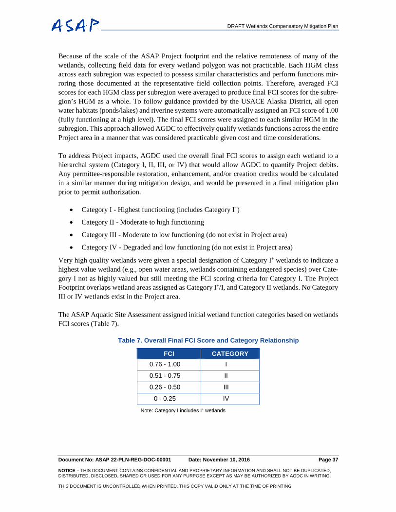
DRAFT Wetlands Compensatory Mitigation Plan
Document No: ASAP 22-PLN-REG-DOC-00001 Date: November 10, 2016 Page 37 NOTICE – THIS DOCUMENT CONTAINS CONFIDENTIAL AND PROPRIETARY INFORMATION AND SHALL NOT BE DUPLICATED, DISTRIBUTED, DISCLOSED, SHARED OR USED FOR ANY PURPOSE EXCEPT AS MAY BE AUTHORIZED BY AGDC IN WRITING. THIS DOCUMENT IS UNCONTROLLED WHEN PRINTED. THIS COPY VALID ONLY AT THE TIME OF PRINTING
Because of the scale of the ASAP Project footprint and the relative remoteness of many of the wetlands, collecting field data for every wetland polygon was not practicable. Each HGM class across each subregion was expected to possess similar characteristics and perform functions mir-roring those documented at the representative field collection points. Therefore, averaged FCI scores for each HGM class per subregion were averaged to produce final FCI scores for the subre-gion’s HGM as a whole. To follow guidance provided by the USACE Alaska District, all open water habitats (ponds/lakes) and riverine systems were automatically assigned an FCI score of 1.00 (fully functioning at a high level). The final FCI scores were assigned to each similar HGM in the subregion. This approach allowed AGDC to effectively qualify wetlands functions across the entire Project area in a manner that was considered practicable given cost and time considerations.
To address Project impacts, AGDC used the overall final FCI scores to assign each wetland to a hierarchal system (Category I, II, III, or IV) that would allow AGDC to quantify Project debits. Any permittee-responsible restoration, enhancement, and/or creation credits would be calculated in a similar manner during mitigation design, and would be presented in a final mitigation plan prior to permit authorization.
• Category I - Highest functioning (includes Category I+)
• Category II - Moderate to high functioning
• Category III - Moderate to low functioning (do not exist in Project area)
• Category IV - Degraded and low functioning (do not exist in Project area)
Very high quality wetlands were given a special designation of Category I+ wetlands to indicate a highest value wetland (e.g., open water areas, wetlands containing endangered species) over Cate-gory I not as highly valued but still meeting the FCI scoring criteria for Category I. The Project Footprint overlaps wetland areas assigned as Category I+/I, and Category II wetlands. No Category III or IV wetlands exist in the Project area.
The ASAP Aquatic Site Assessment assigned initial wetland function categories based on wetlands FCI scores (Table 7).
Table 7. Overall Final FCI Score and Category Relationship
FCI CATEGORY 0.76 - 1.00 I
0.51 - 0.75 II
0.26 - 0.50 III
0 - 0.25 IV
Note: Category I includes I+ wetlands
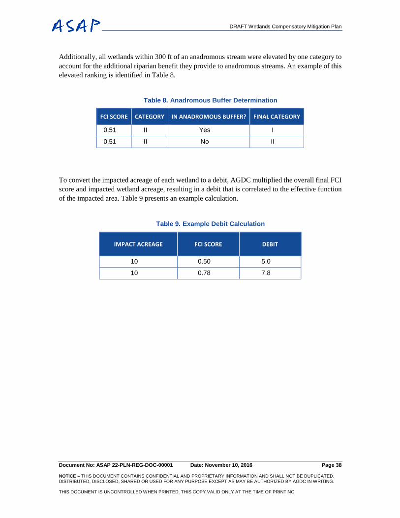
DRAFT Wetlands Compensatory Mitigation Plan
Document No: ASAP 22-PLN-REG-DOC-00001 Date: November 10, 2016 Page 38 NOTICE – THIS DOCUMENT CONTAINS CONFIDENTIAL AND PROPRIETARY INFORMATION AND SHALL NOT BE DUPLICATED, DISTRIBUTED, DISCLOSED, SHARED OR USED FOR ANY PURPOSE EXCEPT AS MAY BE AUTHORIZED BY AGDC IN WRITING. THIS DOCUMENT IS UNCONTROLLED WHEN PRINTED. THIS COPY VALID ONLY AT THE TIME OF PRINTING
Additionally, all wetlands within 300 ft of an anadromous stream were elevated by one category to account for the additional riparian benefit they provide to anadromous streams. An example of this elevated ranking is identified in Table 8.
Table 8. Anadromous Buffer Determination
FCI SCORE CATEGORY IN ANADROMOUS BUFFER? FINAL CATEGORY
0.51 II Yes I
0.51 II No II
To convert the impacted acreage of each wetland to a debit, AGDC multiplied the overall final FCI score and impacted wetland acreage, resulting in a debit that is correlated to the effective function of the impacted area. Table 9 presents an example calculation.
Table 9. Example Debit Calculation
IMPACT ACREAGE FCI SCORE DEBIT
10 0.50 5.0
10 0.78 7.8
DRAFT Wetlands Compensatory Mitigation Plan
Document No: ASAP 22-PLN-REG-DOC-00001 Date: November 10, 2016 Page 39 NOTICE – THIS DOCUMENT CONTAINS CONFIDENTIAL AND PROPRIETARY INFORMATION AND SHALL NOT BE DUPLICATED, DISTRIBUTED, DISCLOSED, SHARED OR USED FOR ANY PURPOSE EXCEPT AS MAY BE AUTHORIZED BY AGDC IN WRITING. THIS DOCUMENT IS UNCONTROLLED WHEN PRINTED. THIS COPY VALID ONLY AT THE TIME OF PRINTING
5. WETLANDS DEBIT CALCULATION METHODOLOGY
As noted in Section 4, above, AGDC recognizes that its wetland debit methodology may not nec-essarily match the methodology of a third party provider to assess available credits. Upon approval of this Compensatory Mitigation Plan, however, AGDC expects to revise its methodology for select areas to match that of the banks from which it expects to purchase credits.
5.1 PARAMETERS FOR WETLANDS DEBIT ANALYSIS
The wetlands debit / credit analysis will use the following parameters to calculate debits: Debit Year, Ecoregion, and 10-Digit HUC code. For additional context as to particular wetland types associated with debits, the HMG classification can be provided upon request. However, the HGM classification is not used in the final tabulations of debits and offsetting credits.
5.1.1 Debit Year
The debit year and the corresponding season of impact were included in the wetlands debit analysis to establish a chronological process by which debits will be tabulated and offset by available credits for each ecoregion and HUC.
5.1.2 Ecoregion
The Northern Ecoregion was subdivided into 3 subregions at the request of the USACE for the purposes of wetlands debit / credit analysis: Arctic Coastal Plain (contains GCF area), Arctic Foot-hills, and Brooks Range. The Interior and Southcentral Ecoregions were not subdivided. The anal-ysis of wetland debits by ecoregion will allow offsetting credits to be applied in that same ecoregion. This is particularly helpful in planning efforts of ILF providers with statewide coverage that intend to compartmentalize mitigation efforts into broader regions for better management.
5.1.3 10-digit HUC Code
HUC codes are assigned nationally to areas to describe the hydrogeographic flow of water. The HUC codes exist and can be displayed at scales ranging from broad to narrow. The greater the number of digits in the HUC code, the narrower the scale of the HUC as a geographic unit. The USACE has requested the use of 10-digit HUC codes for determination of compensatory mitigation needs.
Sixty 10-digit HUC code areas exists within the Project Footprint over three ecoregions:
• 13 in the Northern Ecoregion (Figure 8).
• 32 in the Interior Ecoregion (Figure 9).
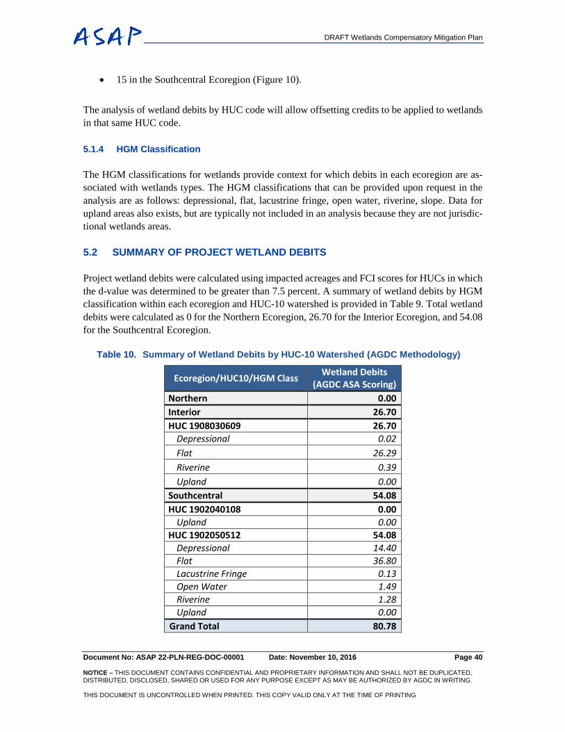
DRAFT Wetlands Compensatory Mitigation Plan
Document No: ASAP 22-PLN-REG-DOC-00001 Date: November 10, 2016 Page 40 NOTICE – THIS DOCUMENT CONTAINS CONFIDENTIAL AND PROPRIETARY INFORMATION AND SHALL NOT BE DUPLICATED, DISTRIBUTED, DISCLOSED, SHARED OR USED FOR ANY PURPOSE EXCEPT AS MAY BE AUTHORIZED BY AGDC IN WRITING. THIS DOCUMENT IS UNCONTROLLED WHEN PRINTED. THIS COPY VALID ONLY AT THE TIME OF PRINTING
• 15 in the Southcentral Ecoregion (Figure 10).
The analysis of wetland debits by HUC code will allow offsetting credits to be applied to wetlands in that same HUC code.
5.1.4 HGM Classification
The HGM classifications for wetlands provide context for which debits in each ecoregion are as-sociated with wetlands types. The HGM classifications that can be provided upon request in the analysis are as follows: depressional, flat, lacustrine fringe, open water, riverine, slope. Data for upland areas also exists, but are typically not included in an analysis because they are not jurisdic-tional wetlands areas.
5.2 SUMMARY OF PROJECT WETLAND DEBITS
Project wetland debits were calculated using impacted acreages and FCI scores for HUCs in which the d-value was determined to be greater than 7.5 percent. A summary of wetland debits by HGM classification within each ecoregion and HUC-10 watershed is provided in Table 9. Total wetland debits were calculated as 0 for the Northern Ecoregion, 26.70 for the Interior Ecoregion, and 54.08 for the Southcentral Ecoregion.
Table 10. Summary of Wetland Debits by HUC-10 Watershed (AGDC Methodology)
Ecoregion/HUC10/HGM Class Wetland Debits (AGDC ASA Scoring)
Northern 0.00 Interior 26.70 HUC 1908030609 26.70
Depressional 0.02 Flat 26.29 Riverine 0.39 Upland 0.00
Southcentral 54.08 HUC 1902040108 0.00
Upland 0.00 HUC 1902050512 54.08
Depressional 14.40 Flat 36.80 Lacustrine Fringe 0.13 Open Water 1.49 Riverine 1.28 Upland 0.00
Grand Total 80.78
DRAFT Wetlands Compensatory Mitigation Plan
Document No: ASAP 22-PLN-REG-DOC-00001 Date: November 10, 2016 Page 41 NOTICE – THIS DOCUMENT CONTAINS CONFIDENTIAL AND PROPRIETARY INFORMATION AND SHALL NOT BE DUPLICATED, DISTRIBUTED, DISCLOSED, SHARED OR USED FOR ANY PURPOSE EXCEPT AS MAY BE AUTHORIZED BY AGDC IN WRITING. THIS DOCUMENT IS UNCONTROLLED WHEN PRINTED. THIS COPY VALID ONLY AT THE TIME OF PRINTING
6. MITIGATION OPTIONS AVAILABLE
6.1 MITIGATION BANKS (SELECTED)
Mitigation banks were selected as the preferred third party entity for applying compensatory miti-gation in this plan. Banks sell credits to permittees to provide compensatory mitigation for impacts authorized by Department of the Army (DA) permits. Mitigation banks typically consist of large restoration or preservation projects that provide compensatory mitigation for a number of activities (33 CFR Parts 325 and 332; 40 CFR Part 230). There is a preference for the use of banks over other forms of mitigation because the mitigation is already accounted for in the bank. Mitigation banks are usually operated for profit by private entities and are governed by an approved instrument. When a permittee’s compensatory mitigation requirements are satisfied by a mitigation bank, re-sponsibility for ensuring that required compensation is completed and successfully shifts from the permittee to that bank (33 CFR Parts 325 and 332; 40 CFR Part 230).
Currently, there are three approved wetland mitigation banks with service areas that coincide with portions of the ASAP Project Footprint where wetland impacts occur: Pioneer Reserve (Lower Susitna River Watershed, MSB), Su Knik Bank (Lower Susitna River Watershed and a small sub-unit of the Southcentral Alaska region subwatershed, MSB), and Tanana Watershed Mitigation Bank (Fairbanks / Interior region). As credits from these banks may be used to offset ASAP Project debits, AGDC has reached out to these banks to determine whether sufficient credits are available to offset impacts. Preliminary discussions indicate that sufficient credits are available through these banks to meet the needs described in this plan. Therefore, upon approval of this plan by the Corps of Engineers, AGDC will move forward to secure these credits.
AGDC recognizes that banks use differing methodologies to determine their credit values. AGDC will match the methodology of the banks in their service areas where the Project wetland debits must be offset by mitigation bank credits.
6.2 ILF PROVIDERS (NOT SELECTED)
ILF providers were considered by AGDC, but were not selected for inclusion in this Compensatory Mitigation Plan because existing mitigation banks currently possess sufficient credits for water-sheds where AGDC will offset substantive unavoidable wetlands impacts.
Mitigation through an ILF provider occurs when a permittee directs funds to an ILF sponsor that in return, sells compensatory mitigation credits. The federal government has acknowledged that ILF programs are important sources of compensatory mitigation because they can provide consol-
DRAFT Wetlands Compensatory Mitigation Plan
Document No: ASAP 22-PLN-REG-DOC-00001 Date: November 10, 2016 Page 42 NOTICE – THIS DOCUMENT CONTAINS CONFIDENTIAL AND PROPRIETARY INFORMATION AND SHALL NOT BE DUPLICATED, DISTRIBUTED, DISCLOSED, SHARED OR USED FOR ANY PURPOSE EXCEPT AS MAY BE AUTHORIZED BY AGDC IN WRITING. THIS DOCUMENT IS UNCONTROLLED WHEN PRINTED. THIS COPY VALID ONLY AT THE TIME OF PRINTING
idated compensatory mitigation projects that have greater ecological benefits than small, geograph-ically separated, permittee-responsible mitigation, they provide important ecological and sociolog-ical benefits by focusing primarily on the watershed needs, and they can site multiple compensatory mitigation projects in strategic locations in a watershed (CFR 33 Parts 325 and 322; 40 CFR 230).
It is recognized that ILF programs are usually not able to capitalize compensatory mitigation pro-jects up-front. Instead, they must collect funds from permittees before they can secure a suitable site and develop and implement a compensatory mitigation project. For this reason, ILF programs, but not banks, are allowed to sell advance credits (although in the lower 48, some banks have been allowed to sell advance credits while enhancement or restoration work is on-going). Unless an ILF program has a surplus of credits available in a service area, the compensatory mitigation will take place after the permitted impacts have occurred. To help ensure that the collected funds are used in a timely manner to initiate compensatory mitigation projects, the federal government established a time limit of three growing seasons for fulfillment of advance credits (332.8(n)(4); 230.90(n)(4)) and required ILF programs to establish accounts to retain the collected funds. Those funds can only be used for the selection, design, acquisition, implementation and management of ILF projects with a small percentage allowed for administrative costs. However, both banks and ILF programs are held to the same mitigation and procedural requirements, including plan approval, performance standards, monitoring, adaptive management, and long-term stewardship.
The activities of restoration, establishment, enhancement, or preservation of aquatic resources be-come the responsibility of the ILF sponsor once credits are purchased. When a permittee’s com-pensatory mitigation requirements are satisfied by an ILF program, responsibility for ensuring that required compensation is completed and successfully shifts from the permittee to the ILF sponsor (33 CFR Parts 325 and 332; 40 CFR Part 230).
ILF programs function by designating funds for activities, such as land preservation, conservation, restoration, or education. These activities are often developed in coordination with projects that impact adjacent lands and that require a purchase of credits to offset wetland debits. These debits are calculated through the use of a given methodology in an ASA (formerly ‘Functional Assess-ment’). It has been common for ILF providers to use the ASA methodology in deriving credits that projects have also used to derive debits, thereby allowing for similar methodologies to be applied.
ILF programs are generally administered by state governments, local governments, and non-profit / non-governmental organizations. In Alaska, three approved ILF sponsors exist: The Conservation Fund (TCF) (serves the entire state), Great Land Trust (serves the Municipality of Anchorage), and Southeast Alaska Land Trust (SEAL Trust) (serves Southeast Alaska). TCF is the only ILF program with an approved instrument covering the entire state of Alaska. Great Land Trust and SEAL Trust are outside of the Project Service area, and would not be utilized for the Project. A fourth potential ILF sponsor that has not yet been approved is that of the State of Alaska (SOA) ADNR. An ap-proved SOA instrument could potentially also cover the entire state.
DRAFT Wetlands Compensatory Mitigation Plan
Document No: ASAP 22-PLN-REG-DOC-00001 Date: November 10, 2016 Page 43 NOTICE – THIS DOCUMENT CONTAINS CONFIDENTIAL AND PROPRIETARY INFORMATION AND SHALL NOT BE DUPLICATED, DISTRIBUTED, DISCLOSED, SHARED OR USED FOR ANY PURPOSE EXCEPT AS MAY BE AUTHORIZED BY AGDC IN WRITING. THIS DOCUMENT IS UNCONTROLLED WHEN PRINTED. THIS COPY VALID ONLY AT THE TIME OF PRINTING
6.2.1 The Conservation Fund
TCF currently operates in five distinct geographic service areas (Arctic, Interior, Southcentral, Southeast, and Southwest). When combined, these service areas cover the entire jurisdictional area of the USACE’s Alaska District. Advanced credits are supplied by USACE to the sponsor, and the sponsor is then responsible for all operational and reporting requirements.
TCF is currently limiting the availability of credits and may not provide any for certain portions of their service area. AGDC anticipates that it will be able to purchase some credits from TCF. The TCF has previously used the Cowardin Classification - Acres approach around the state for various projects, as well as AKWAM in the Interior for Alaska Department of Transportation and Public Facilities (ADOT&PF) projects.
6.2.2 The Proposed State of Alaska ILF Program
The SOA ADNR is proposing a state-run ILF program that could be utilized by the ASAP Project. The program is in development. Currently the USACE is doing an informal review of the State’s draft prospectus. Following receipt of comments, the ADNR expects to resubmit a revised version for a more formal review by the USACE and an interagency review team. Any mitigation identified on State of Alaska lands by this program would need to undergo a thorough internal review to assure that any restriction of rights of lands is in the best interest of the State and not encumbering any existing rights for adjacent or nearby land owners or users.
6.3 PERMITTEE RESPONSIBLE MITIGATION (PRM) (NOT SELECTED)
PRM was considered by AGDC, but was not selected for inclusion in this Compensatory Mitigation Plan because existing mitigation banks currently possess sufficient credits for watersheds where AGDC must offset substantive unavoidable wetlands impacts.
Permittee PRM includes the restoration, establishment, enhancement or preservation of wetlands undertaken by a permittee to compensate for wetland impacts resulting from a specific project. The permittee performs the mitigation after the permit is issued and is ultimately responsible for the implementation and success of mitigation. With PRM, the permittee maintains liability for the con-struction and long-term success of the site. PRM is to be managed under a watershed approach; the goal is to improve the quality and quantity of aquatic resources within the impacted watershed through the selection of compensatory mitigation sites and projects.
The Mitigation Rule identifies three types of PRM Projects in USACE preference:
1.) On-site and in-kind - PRM projects are managed in the same watershed, and within the same wetland habitat types.
2.) Off-site and in-kind - PRM projects are managed in a different watershed, with the same wetland habitat types.
DRAFT Wetlands Compensatory Mitigation Plan
Document No: ASAP 22-PLN-REG-DOC-00001 Date: November 10, 2016 Page 44 NOTICE – THIS DOCUMENT CONTAINS CONFIDENTIAL AND PROPRIETARY INFORMATION AND SHALL NOT BE DUPLICATED, DISTRIBUTED, DISCLOSED, SHARED OR USED FOR ANY PURPOSE EXCEPT AS MAY BE AUTHORIZED BY AGDC IN WRITING. THIS DOCUMENT IS UNCONTROLLED WHEN PRINTED. THIS COPY VALID ONLY AT THE TIME OF PRINTING
3.) Off-site and out-of-kind - PRM projects are not located in the same watershed, and are out-of-kind habitat replacement. This third option is the least desirable option to USACE. The restoration or enhancement work is completed outside of the impact site and is not replacing in-kind impact habitat.
Each PRM project follows the requirements of the Mitigation Rule. They are individual develop-ments standing on their own merits. The permittee provides detail-driven plans, and assures credits can be constructed at the site. USACE monitors for a minimum of five years to make sure the sites are performing as planned. The permittee retains the full responsibility for the protection and man-agement of the PRM site (33 CFR 332.4(c)(2-14) with a long-term protection instrument that must be managed into perpetuity.
While PRM can be used in Alaska, it is often impracticable to restore wetlands as many of the locations are remote and have short growing seasons. This is especially true on the North Slope because it is a highly seasonal environment with a short growing season where terrain is dominated by permafrost-driven wetlands. In forested wetlands to the south, there are equally remote areas where it can still take many decades or even centuries to restore trees due to highly seasonal envi-ronments and short growing seasons. In many cases, PRM in Alaska may require staging or mobi-lizing equipment in remote areas over multiple seasons, possibly for several decades. Additionally, PRM may not be the most appropriate method based on the size of watershed and resources avail-able there.
There are other regulatory challenges that could also limit use of PRM on the ASAP Project. For instance, the Alaska State Constitution contains provisions that could prohibit perpetual protection instruments. Other challenges could be that certain types of PRM fall under a compliance require-ment (e.g., restoration or removal of existing culverts) and therefore can’t be used for mitigation because they wouldn’t contribute to a net gain. Several of these factors support the preference hi-erarchy established under the 2008 Mitigation Rule, which prefers the use of approved mitigation banks and ILF providers over PRM.

DRAFT Wetlands Compensatory Mitigation Plan
Document No: ASAP 22-PLN-REG-DOC-00001 Date: November 10, 2016 Page 45 NOTICE – THIS DOCUMENT CONTAINS CONFIDENTIAL AND PROPRIETARY INFORMATION AND SHALL NOT BE DUPLICATED, DISTRIBUTED, DISCLOSED, SHARED OR USED FOR ANY PURPOSE EXCEPT AS MAY BE AUTHORIZED BY AGDC IN WRITING. THIS DOCUMENT IS UNCONTROLLED WHEN PRINTED. THIS COPY VALID ONLY AT THE TIME OF PRINTING
7. CONCLUSIONS
The ASAP Project is designed as a long, linear natural gas pipeline that will provide gas to Alaskan residents, businesses and other entities in the state. The Project will transect 60 HUC-10 watersheds in Alaska’s Northern, Interior and Southcentral ecosystems. A narrow corridor and several off-ROW facilities are required for construction and operation of the pipeline, but will result in new unavoidable wetland impacts.
AGDC has implemented measures to avoid and minimize impacts to wetlands where practicable. Avoidance of open water areas and higher value wetlands were a priority, often through winter construction and routing the pipeline into upland areas. Minimization of wetlands impacts occurred by selectively routing the pipeline through areas in which fewer wetlands and lower value wetlands occurred. In some areas, minimization also occurred through the use of construction methods that would only have temporary impacts. Following wetland avoidance and minimization, remaining impacts will be offset through compensatory mitigation. AGDC has structured its compensatory mitigation using a watershed approach, applying appropriate and practicable mitigation to unavoid-able project impacts.
Aquatic resources and functions of watersheds can be negatively impacted by development. Im-pacts associated with urbanization are substantive, or statistically significant, when approximately 10 percent of land cover in a watershed is developed and converted to impervious surfaces, com-pacted surfaces, agricultural land, barren land, or other type of land. Different types of anthropo-genic land cover changes have been measured reliably for over 15 years using aerial photography, computer sensors, and GIS software and have been made publicly available for use through the NLCD. AGDC used the NLCD and its own GIS database to determine which HUC-10 watersheds have been substantively impacted by development and would be substantively impacted by the ASAP Project. It then measured its wetlands impacts in those HUC-10 watersheds to help structure appropriate and practicable mitigation for the substantive, unavoidable impacts of the Project.
The ASAP Project will not generate substantive impacts to watersheds in the Northern Ecoregion, but will generate substantive wetlands impacts to watersheds in the Interior Ecoregion (34.12 acres) and the Southcentral Ecoregion (70.85 acres). Using an FCI scoring methodology developed by its wetlands consultants, AGDC calculated its total wetland debits as 26.70 for the Interior Ecoregion and 54.08 for the Southcentral Ecoregion. However, AGDC recognizes the need to match its meth-odology to that of a third party provider. AGDC has preliminary confirmation that sufficient credits exist from banks in service areas where the Project must offset substantive unavoidable impacts to wetlands. AGDC intends to match the methodology of these providers and purchase the credits required to offset the substantive unavoidable impacts to wetlands in these watersheds.
DRAFT Wetlands Compensatory Mitigation Plan
Document No: ASAP 22-PLN-REG-DOC-00001 Date: November 10, 2016 Page 46 NOTICE – THIS DOCUMENT CONTAINS CONFIDENTIAL AND PROPRIETARY INFORMATION AND SHALL NOT BE DUPLICATED, DISTRIBUTED, DISCLOSED, SHARED OR USED FOR ANY PURPOSE EXCEPT AS MAY BE AUTHORIZED BY AGDC IN WRITING. THIS DOCUMENT IS UNCONTROLLED WHEN PRINTED. THIS COPY VALID ONLY AT THE TIME OF PRINTING
REFERENCES
AGDC. 2014. Plan of Development. October, 2014. Available online at http://asapgas.agdc.us/doc-uments.html. AGDC. 2015a. Joint Application for Permit (404 / 10). December 29, 2015. Submitted to the USACE in January 2016. AGDC. 2015b. Design Basis – Pipeline. Alaska Stand Alone Pipeline Project. Sept 17, 2015. 002-C-27-BDC-YYY-0001. AGDC. 2015c. Addendum to the 2014 Plan of Development. October 2, 2015. ASAP Interactive Webviewer at: http://asapgas.agdc.us/interactivemap.html. AGDC. 2015d. Streambank Restoration Manual. February 6, 2015. ASAP-27-MTM-CCC-DOC-00001. AGDC. 2015e. Project Note: Stream Crossing Design Procedures. January 12, 2015. ASAP-27-PRO-CCC-DOC-00001 Baker, M. E., and King, R. S. 2010. A new method for detecting and interpreting biodiversity and ecological community thresholds. Methods in Ecology and Evolution 1:25-37. Booth, D. 1991. Urbanization and the natural drainage system-impacts, solutions and prognoses. Northwest Environmental Journal. 7(1): 93-118. Booth, D.B, Montgomery, D. R., and Bethel, J. 1996. Large Woody Debris in Urban Streams of the Pacific Northwest. In: Effects of Watershed Development and Management on Aquatic Eco-systems, L.A. Roesner (Editor). Engineering Foundation Conference Proceedings, Snowbird, Utah, August 4-9, 1996. Pp. 178-197. Hicks, A.L. and J.S. Larson. 1997. The Impact of Urban Stormwater Runoff on Freshwater Wet-lands and the Role of Aquatic Invertebrate Bioassessment. The Environment Institute, University of Massachusetts. Amherst, MA. Hilderbrand, R.H., R.M. Utz, S.A. Stranko, and R.L. Raesly. 2010. Applying thresholds to forecast potential biodiversity loss from human development. Journal of the North American Benthological Society 29(3):1009-1016. Jones, R. and C. Clark. 1987. Impact of Watershed Urbanization on Stream Insect Communities. American Water Resources Association. Water Resources Bulletin. 15(4). Klein, R. 1997. Urbanization and stream Quality Impairment. Water Resources Bulletin 15:948-963.
DRAFT Wetlands Compensatory Mitigation Plan
Document No: ASAP 22-PLN-REG-DOC-00001 Date: November 10, 2016 Page 47 NOTICE – THIS DOCUMENT CONTAINS CONFIDENTIAL AND PROPRIETARY INFORMATION AND SHALL NOT BE DUPLICATED, DISTRIBUTED, DISCLOSED, SHARED OR USED FOR ANY PURPOSE EXCEPT AS MAY BE AUTHORIZED BY AGDC IN WRITING. THIS DOCUMENT IS UNCONTROLLED WHEN PRINTED. THIS COPY VALID ONLY AT THE TIME OF PRINTING
Limburg, K and R. Schimdt. 1990. Patterns of fish spawning in Hudson river tributaries- response to an urban gradient?. Ecology 71(4): 1231-1245. Luchetti, G and R. Fuersteburg, 1993. Relative fish use in urban and non-urban streams. Proceed-ings. Conference on Wild Salmon. Vancouver, British Columbia. Magee, D.W. 1998. A Rapid Procedure for Assessing Wetland Functional Capacity. Technical Contributions from G.G. Hollands. Bedford, NH. May, C. R. Horner, J. Karr, B. Mar, and E. Welch. 1997. Effects of Urbanization on Small Streams In the Puget Sound Lowland Ecoregion. Watershed Protection Techniques, 2(4): 483-494. Metropolitan Washington Council of Governments (MWCOG), 1992. Watershed Restoration Sourcebook. Department of Environmental Programs, MWCOG, Washington, DC. Schueler, T. R., Fraley-McNeal, L., and Cappiella, K. 2009. Is impervious cover still important? Review of recent research. Journal of Hydrologic Engineering 14:309-315. Steedman, R. J. 1988. Modification and assessment of an index of biotic integrity to quantify stream quality in Southern Ontario. Canadian Journal of Fisheries and Aquatic Sciences. 45:492-501. Stormwater Manager’s Resource Center. 2016. Impervious Cover Model. http://www.stormwater-center.net/ U.S. Army Corps of Engineers (USACE). 2012a. Draft Environmental Impact Statement. Alaska Stand Alone Pipeline. January. USACE. 2012b. Final Environmental Impact Statement. Alaska Stand Alone Pipeline. October. Utz, R. M., Hilderbrand, R. H., and Boward, D. M. 2009. Identifying regional differences in thresh-old responses of aquatic invertebrates to land cover gradients. Ecological Indicators 9:556-567. Weaver, L.A. 1991. Low-Intensity Watershed Alteration Effects on Fish Assemblage Structure and Function in a Virginia Piedmont Stream. Unpublished Masters Thesis. Virginia Commonwealth University. 77 pp. Wright, S. A revegetation manual for Alaska. Alaska Plant Materials Center. Alaska Department of Natural Resources.

DRAFT Wetlands Compensatory Mitigation Plan
Document No: ASAP 22-PLN-REG-DOC-00001 Date: November 10, 2016 Page 48 NOTICE – THIS DOCUMENT CONTAINS CONFIDENTIAL AND PROPRIETARY INFORMATION AND SHALL NOT BE DUPLICATED, DISTRIBUTED, DISCLOSED, SHARED OR USED FOR ANY PURPOSE EXCEPT AS MAY BE AUTHORIZED BY AGDC IN WRITING. THIS DOCUMENT IS UNCONTROLLED WHEN PRINTED. THIS COPY VALID ONLY AT THE TIME OF PRINTING
APPENDIX A
DATA VALIDATION AND ANALYSIS FOR EXISTING ANTHROPOGENIC DISTURBANCES AND PROJECT WETLANDS IMPACTS TO DERIVE A
MAXIMUM DISTURBED VALUE (D-VALUE) FOR HUC-10 WATERSHEDS
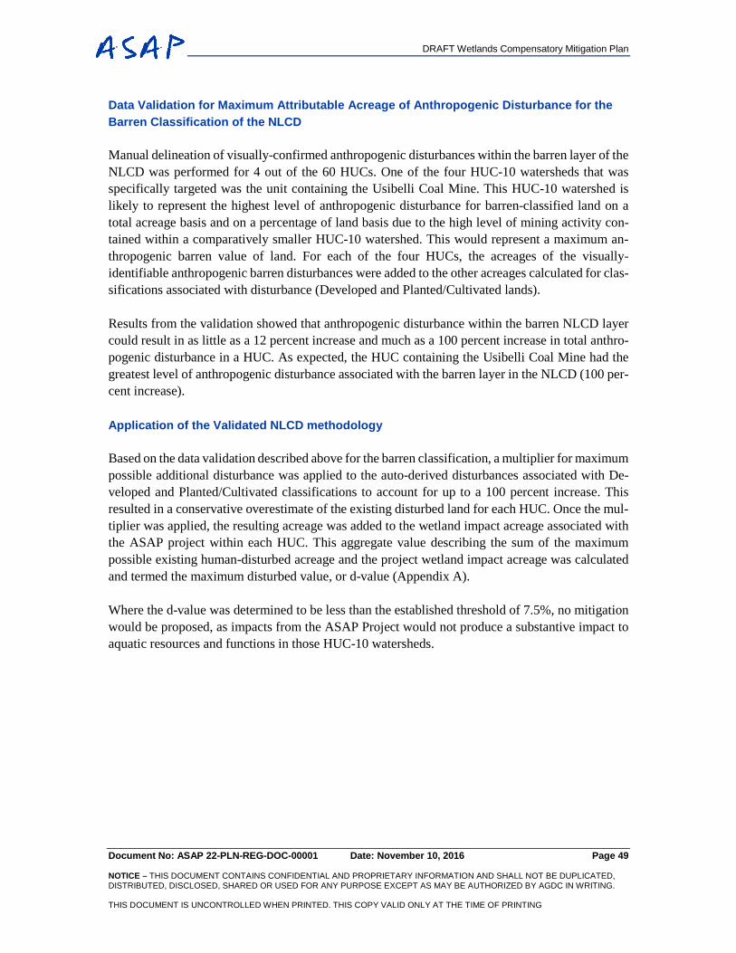
DRAFT Wetlands Compensatory Mitigation Plan
Document No: ASAP 22-PLN-REG-DOC-00001 Date: November 10, 2016 Page 49 NOTICE – THIS DOCUMENT CONTAINS CONFIDENTIAL AND PROPRIETARY INFORMATION AND SHALL NOT BE DUPLICATED, DISTRIBUTED, DISCLOSED, SHARED OR USED FOR ANY PURPOSE EXCEPT AS MAY BE AUTHORIZED BY AGDC IN WRITING. THIS DOCUMENT IS UNCONTROLLED WHEN PRINTED. THIS COPY VALID ONLY AT THE TIME OF PRINTING
Data Validation for Maximum Attributable Acreage of Anthropogenic Disturbance for the Barren Classification of the NLCD
Manual delineation of visually-confirmed anthropogenic disturbances within the barren layer of the NLCD was performed for 4 out of the 60 HUCs. One of the four HUC-10 watersheds that was specifically targeted was the unit containing the Usibelli Coal Mine. This HUC-10 watershed is likely to represent the highest level of anthropogenic disturbance for barren-classified land on a total acreage basis and on a percentage of land basis due to the high level of mining activity con-tained within a comparatively smaller HUC-10 watershed. This would represent a maximum an-thropogenic barren value of land. For each of the four HUCs, the acreages of the visually-identifiable anthropogenic barren disturbances were added to the other acreages calculated for clas-sifications associated with disturbance (Developed and Planted/Cultivated lands). Results from the validation showed that anthropogenic disturbance within the barren NLCD layer could result in as little as a 12 percent increase and much as a 100 percent increase in total anthro-pogenic disturbance in a HUC. As expected, the HUC containing the Usibelli Coal Mine had the greatest level of anthropogenic disturbance associated with the barren layer in the NLCD (100 per-cent increase). Application of the Validated NLCD methodology
Based on the data validation described above for the barren classification, a multiplier for maximum possible additional disturbance was applied to the auto-derived disturbances associated with De-veloped and Planted/Cultivated classifications to account for up to a 100 percent increase. This resulted in a conservative overestimate of the existing disturbed land for each HUC. Once the mul-tiplier was applied, the resulting acreage was added to the wetland impact acreage associated with the ASAP project within each HUC. This aggregate value describing the sum of the maximum possible existing human-disturbed acreage and the project wetland impact acreage was calculated and termed the maximum disturbed value, or d-value (Appendix A). Where the d-value was determined to be less than the established threshold of 7.5%, no mitigation would be proposed, as impacts from the ASAP Project would not produce a substantive impact to aquatic resources and functions in those HUC-10 watersheds.
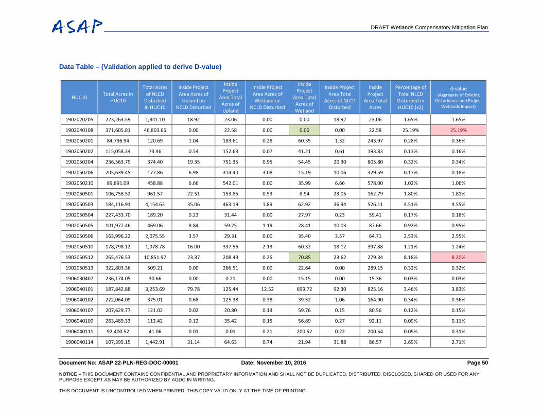
DRAFT Wetlands Compensatory Mitigation Plan
Document No: ASAP 22-PLN-REG-DOC-00001 Date: November 10, 2016 Page 50 NOTICE – THIS DOCUMENT CONTAINS CONFIDENTIAL AND PROPRIETARY INFORMATION AND SHALL NOT BE DUPLICATED, DISTRIBUTED, DISCLOSED, SHARED OR USED FOR ANY PURPOSE EXCEPT AS MAY BE AUTHORIZED BY AGDC IN WRITING. THIS DOCUMENT IS UNCONTROLLED WHEN PRINTED. THIS COPY VALID ONLY AT THE TIME OF PRINTING
Data Table – (Validation applied to derive D-value)
HUC10 Total Acres in HUC10
Total Acres of NLCD
Disturbed in HUC10
Inside Project Area Acres of
Upland on NCLD Disturbed
Inside Project
Area Total Acres of Upland
Inside Project Area Acres of Wetland on
NCLD Disturbed
Inside Project
Area Total Acres of Wetland
Inside Project Area Total
Acres of NLCD Disturbed
Inside Project
Area Total Acres
Percentage of Total NLCD Disturbed in HUC10 (x2)
d-value (Aggregate of Existing
Disturbance and Project Wetlands Impact)
1902020205 223,263.59 1,841.10 18.92 23.06 0.00 0.00 18.92 23.06 1.65% 1.65%
1902040108 371,605.81 46,803.66 0.00 22.58 0.00 0.00 0.00 22.58 25.19% 25.19%
1902050201 84,796.94 120.69 1.04 183.61 0.28 60.35 1.32 243.97 0.28% 0.36%
1902050202 115,058.34 73.46 0.54 152.63 0.07 41.21 0.61 193.83 0.13% 0.16%
1902050204 236,563.79 374.40 19.35 751.35 0.95 54.45 20.30 805.80 0.32% 0.34%
1902050206 205,639.45 177.86 6.98 314.40 3.08 15.19 10.06 329.59 0.17% 0.18%
1902050210 89,891.09 458.88 6.66 542.01 0.00 35.99 6.66 578.00 1.02% 1.06%
1902050501 106,758.52 961.57 22.51 153.85 0.53 8.94 23.05 162.79 1.80% 1.81%
1902050503 184,116.91 4,154.63 35.06 463.19 1.89 62.92 36.94 526.11 4.51% 4.55%
1902050504 227,433.70 189.20 0.23 31.44 0.00 27.97 0.23 59.41 0.17% 0.18%
1902050505 101,977.46 469.06 8.84 59.25 1.19 28.41 10.03 87.66 0.92% 0.95%
1902050506 163,996.22 2,075.55 3.57 29.31 0.00 35.40 3.57 64.71 2.53% 2.55%
1902050510 178,798.12 1,078.78 16.00 337.56 2.13 60.32 18.12 397.88 1.21% 1.24%
1902050512 265,476.53 10,851.97 23.37 208.49 0.25 70.85 23.62 279.34 8.18% 8.20%
1902050513 322,803.36 509.21 0.00 266.51 0.00 22.64 0.00 289.15 0.32% 0.32%
1906030407 236,174.05 30.66 0.00 0.21 0.00 15.15 0.00 15.36 0.03% 0.03%
1906040101 187,842.88 3,253.69 79.78 125.44 12.52 699.72 92.30 825.16 3.46% 3.83%
1906040102 222,064.09 375.01 0.68 125.38 0.38 39.52 1.06 164.90 0.34% 0.36%
1906040107 207,629.77 121.02 0.02 20.80 0.13 59.76 0.15 80.56 0.12% 0.15%
1906040109 263,489.33 112.42 0.12 35.42 0.15 56.69 0.27 92.11 0.09% 0.11%
1906040111 92,400.52 41.06 0.01 0.01 0.21 200.52 0.22 200.54 0.09% 0.31%
1906040114 107,395.15 1,442.91 31.14 64.63 0.74 21.94 31.88 86.57 2.69% 2.71%

DRAFT Wetlands Compensatory Mitigation Plan
Document No: ASAP 22-PLN-REG-DOC-00001 Date: November 10, 2016 Page 51 NOTICE – THIS DOCUMENT CONTAINS CONFIDENTIAL AND PROPRIETARY INFORMATION AND SHALL NOT BE DUPLICATED, DISTRIBUTED, DISCLOSED, SHARED OR USED FOR ANY PURPOSE EXCEPT AS MAY BE AUTHORIZED BY AGDC IN WRITING. THIS DOCUMENT IS UNCONTROLLED WHEN PRINTED. THIS COPY VALID ONLY AT THE TIME OF PRINTING
HUC10 Total Acres in HUC10
Total Acres of NLCD
Disturbed in HUC10
Inside Project Area Acres of
Upland on NCLD Disturbed
Inside Project
Area Total Acres of Upland
Inside Project Area Acres of Wetland on
NCLD Disturbed
Inside Project
Area Total Acres of Wetland
Inside Project Area Total
Acres of NLCD Disturbed
Inside Project
Area Total Acres
Percentage of Total NLCD Disturbed in HUC10 (x2)
d-value (Aggregate of Existing
Disturbance and Project Wetlands Impact)
1906040117 145,949.30 124.10 27.41 29.66 11.02 71.90 38.43 101.56 0.17% 0.21%
1906040201 213,684.57 1,191.74 27.27 409.59 82.21 582.18 109.48 991.77 1.12% 1.35%
1906040204 241,007.35 231.97 0.65 95.25 0.61 167.75 1.26 263.01 0.19% 0.26%
1906040208 200,383.87 1,179.66 1.02 325.70 1.08 844.48 2.10 1,170.17 1.18% 1.60%
1906040216 237,666.23 1,656.56 33.07 56.91 8.12 959.27 41.19 1,016.18 1.39% 1.79%
1906040217 516,566.67 1,805.86 10.36 16.16 1.11 252.37 11.47 268.53 0.70% 0.75%
1908020101 247,417.74 292.27 6.22 57.40 0.27 121.36 6.49 178.76 0.24% 0.29%
1908030609 142,189.00 30,906.10 26.31 43.60 0.07 34.12 26.38 77.72 43.47% 43.50%
1908030803 248,009.14 724.00 2.92 208.84 1.25 118.57 4.16 327.42 0.58% 0.63%
1908030806 144,188.13 0.00 0.00 11.42 0.00 4.04 0.00 15.46 0.00% 0.00%
1908030807 232,569.15 706.35 26.49 761.67 0.64 230.94 27.13 992.61 0.61% 0.71%
1908030809 229,037.39 1,769.93 28.32 424.18 0.75 356.02 29.07 780.21 1.55% 1.70%
1908030812 226,587.29 269.76 3.55 103.18 0.52 39.91 4.07 143.09 0.24% 0.26%
1908030813 232,274.66 1,754.41 0.73 285.10 0.02 183.85 0.74 468.94 1.51% 1.59%
1908030901 186,588.06 483.29 83.98 242.25 0.47 75.25 84.45 317.50 0.52% 0.56%
1908030902 237,482.90 1,225.08 0.79 177.86 0.01 65.05 0.80 242.91 1.03% 1.06%
1908030903 219,440.69 571.69 0.00 148.27 0.00 1.64 0.00 149.91 0.52% 0.52%
1908030904 169,966.06 456.52 0.00 131.79 0.00 56.64 0.00 188.44 0.54% 0.57%
1908030907 211,445.93 5,178.24 17.26 176.92 1.07 16.70 18.33 193.61 4.90% 4.91%
1908030908 176,458.90 1,009.56 0.74 541.32 0.00 229.78 0.74 771.10 1.14% 1.27%
1908030909 129,953.87 58.92 3.59 253.90 2.74 81.58 6.34 335.48 0.09% 0.15%
1908030910 268,992.41 660.91 0.81 426.63 0.25 88.34 1.06 514.96 0.49% 0.52%
1908031102 176,810.78 183.69 14.10 113.06 0.39 48.18 14.48 161.24 0.21% 0.23%
1908040320 221,418.48 420.17 3.47 69.07 1.32 145.50 4.80 214.57 0.38% 0.44%
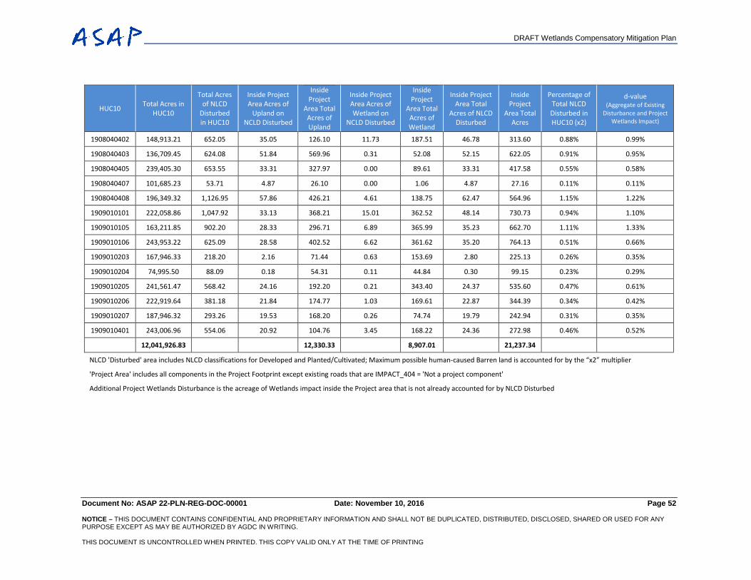
DRAFT Wetlands Compensatory Mitigation Plan
Document No: ASAP 22-PLN-REG-DOC-00001 Date: November 10, 2016 Page 52 NOTICE – THIS DOCUMENT CONTAINS CONFIDENTIAL AND PROPRIETARY INFORMATION AND SHALL NOT BE DUPLICATED, DISTRIBUTED, DISCLOSED, SHARED OR USED FOR ANY PURPOSE EXCEPT AS MAY BE AUTHORIZED BY AGDC IN WRITING. THIS DOCUMENT IS UNCONTROLLED WHEN PRINTED. THIS COPY VALID ONLY AT THE TIME OF PRINTING
HUC10 Total Acres in HUC10
Total Acres of NLCD
Disturbed in HUC10
Inside Project Area Acres of
Upland on NCLD Disturbed
Inside Project
Area Total Acres of Upland
Inside Project Area Acres of Wetland on
NCLD Disturbed
Inside Project
Area Total Acres of Wetland
Inside Project Area Total
Acres of NLCD Disturbed
Inside Project
Area Total Acres
Percentage of Total NLCD Disturbed in HUC10 (x2)
d-value (Aggregate of Existing
Disturbance and Project Wetlands Impact)
1908040402 148,913.21 652.05 35.05 126.10 11.73 187.51 46.78 313.60 0.88% 0.99%
1908040403 136,709.45 624.08 51.84 569.96 0.31 52.08 52.15 622.05 0.91% 0.95%
1908040405 239,405.30 653.55 33.31 327.97 0.00 89.61 33.31 417.58 0.55% 0.58%
1908040407 101,685.23 53.71 4.87 26.10 0.00 1.06 4.87 27.16 0.11% 0.11%
1908040408 196,349.32 1,126.95 57.86 426.21 4.61 138.75 62.47 564.96 1.15% 1.22%
1909010101 222,058.86 1,047.92 33.13 368.21 15.01 362.52 48.14 730.73 0.94% 1.10%
1909010105 163,211.85 902.20 28.33 296.71 6.89 365.99 35.23 662.70 1.11% 1.33%
1909010106 243,953.22 625.09 28.58 402.52 6.62 361.62 35.20 764.13 0.51% 0.66%
1909010203 167,946.33 218.20 2.16 71.44 0.63 153.69 2.80 225.13 0.26% 0.35%
1909010204 74,995.50 88.09 0.18 54.31 0.11 44.84 0.30 99.15 0.23% 0.29%
1909010205 241,561.47 568.42 24.16 192.20 0.21 343.40 24.37 535.60 0.47% 0.61%
1909010206 222,919.64 381.18 21.84 174.77 1.03 169.61 22.87 344.39 0.34% 0.42%
1909010207 187,946.32 293.26 19.53 168.20 0.26 74.74 19.79 242.94 0.31% 0.35%
1909010401 243,006.96 554.06 20.92 104.76 3.45 168.22 24.36 272.98 0.46% 0.52%
12,041,926.83 12,330.33 8,907.01 21,237.34
NLCD 'Disturbed' area includes NLCD classifications for Developed and Planted/Cultivated; Maximum possible human-caused Barren land is accounted for by the “x2” multiplier
'Project Area' includes all components in the Project Footprint except existing roads that are IMPACT_404 = 'Not a project component'
Additional Project Wetlands Disturbance is the acreage of Wetlands impact inside the Project area that is not already accounted for by NLCD Disturbed