Embed Size (px)
Citation preview

ALASKA DEPARTMENT OF FISH AND GAME
Shocic Waves (Air)
'r
Shock h a (Earth or Whr)
BLASTING STANDARDS
For the Protection of Fish


Rationale for Blasting Standards (11 M C 95) Developed to Prevent Explosive Injury to Fish
As interest in Alaska's resource~development grows, the use of
high explosives in conjunction with seismic exploration, rock
quarrying, and road construction increases. Indiscriminate use
of explosives in or near waterbodies, especially critical marine
habitat and anadromous and high value resident fish streams and
lakes, is potentially harmful to fish. Pursuant to AS 16.05.870
(the Anadromous Fish Act) and 11 AAC 95 (the Forest Practices
Act), the Alaska Department of Fish and Game (ADFtG) has
developed blasting standards for use near critical fish habitat.
ADF&G1s blasting standards (11 AAC 95.248) state that llWithout
prior written approval from the Department of Fish and Game, no
person may discharge an explosive that produces or is likely to
produce an instantaneous pressure change greater than 2.7 pounds
per square inch (psi) in the swim bladder of a fish or produces
or is likely to produce a peak particle velocity greater than
0.5 inches per second (ips) in a spawning bed during the early
stage of egg in~ubation.~~ These standards result from a
thorough review of the available literature and represent
ADF&Gts considered opinion on the maximum allowable blast impact
within fish habitat.
FEBRUARY 15, 1991

P hvsical Phenomena Associated. with Blas t inq
~xplosives are chemical substances which, when detonated,
instantaneously release large quantities of energy. Common
explosives derive energy from chemical reactions such as
oxidation (deflagration) of black powder or breaking of high
energy chemical bonds (detonation) as in trinitrotoluene (TNT) . In a deflagration, the reaction moves too slowly (less than
3,000 feet per second) to produce significant shock waves and is
considered relatively harmless to fish (Hubbs and Rechnitzer,
1952). The detonation velocity of today's commercial explosives
ranges from about 5,000 feet per second for ammonium nitrate-
fuel oil (ANFO) compounds, up to 22,000 feet per second for
detonating cords and certain primers (DuPont, 1980). These are
the ranges of detonation velocities that produce the significant
shock waves and instantaneous pressure changes that injure or
kill fish.
Explosive energy is released as pressure, light, and heat
(Figure 1). This energy generates a shock wave through the
surrounding med-ium (air, soil, water) . As the wave spreads from the source, its energy is distributed over an area inversely
proportional to the radius. Thus, energy per unit area varies
inversely to the square of the distance from the source,
explaining in part the attenuation of shock waves over distance.
Explosives detonated underground produce pressure or seismic
waves within the earth (Figure 2). Two modes of seismic wave
DRAFT -2- FEBRUARY 15, 1991

1' Shock W a r m 8 ( A i r )
FIGURE 1. DISSIPATION OF EXPLOSIVE ENERGY
DRAFT
Surf aco
Body Waves
FIGURE 2. SEISMIC WAVES
-3- FEBRUARY 15, 1991

have been identified; body waves and surface waves. Two types
of body waves are propagated through the earth: compressional
(Primary or llP1l) waves and shear (Secondary or "St') waves.
Compressional waves have higher velocities than shear waves and
are propagated from the earth into water bodies.
The second mode of wave propagation is along the earth's
surface. Surface waves are usually produced when a body wave
travels to the surface and is reflected back. These waves
contribute to ground vibrations that are potentially lethal to
incubating fish eggs.
Underwater shock waves generated by explosives are compressional
waves with almost instantaneous rise times to peak pressure
followed by an exponential decay and negative pressure
(rarefaction) relative to ambient conditions (Cole, 1948; Figure
3) . In terms of their effect on fish, shock waves generated by
inwater explosions have a greater lethal effect than waves
propagated from the ground into water because they exhibit a
sharper pressure-time signature and, in underground explosions,
part of the energy is reflected and lost at the ground-water
interface.
Effect of Com~ression Waves on Fish
High instantanedus peak pressures followed by rarefaction can
traumatize and kill fish (Hubbs and Rechnitzer, 1952; Wright,
1982). Injuries range from scale loss to ruptured internal
DRAFT -4- FEBRUARY 15, 1991


organs. While heart, kidney, blood vessels, spleen, liver, and
gonads may be injured, the swim bladder is most sensitive to
pressure change (Alpin, 1947; Hubbs and Rechnitzer, 1952;
Christian, 1973; Falk and Lawrence, 1973; Yelverton, et al.,
1975; Wright, 1982). Fish without swim bladders are relatively
insensitive to underwater.shock waves (Alpin, 1947). However,
almost all Alaskan fish species important to sport, commercial,
and subsistence fisheries have swim bladders.
The swim bladder is the hydrostatic organ that maintains
buoyancy and stability in fish. Swim bladders can respond to a
wide range of pressure changes; however, exposure to rapid
pressure variations caused by explosions may not be
accommodated. When subjected to pressure variations greater
than the limits of accommodation, the swim bladder will
experience trauma ranging from slight tissue strain to complete
rupture leading to massive internal hemorrhaging. Mortality is
caused either directly by trauma or indirectly through loss of
equilibrium resulting in increased susceptibility to predation-
or inability to feed. No difference in response has been noted
between fish that have ducted bladders (physotomatous) and those
with closed swim bladders (physoclistous).
Body shape and orientation with respect to the wavefront affects
susceptibility to pressure changes. Fish with cylindrical
bodies are less likely to be injured by rapid pressure changes
than those with dorsoventrally flattened bodies exhibiting a
high surface area to volume ratio. Body size also has been
DRAPT -6- FEBRUARY 15, 1991

correlated to injury (Yelverton, et al., 1975). Smaller fish
are more likely to be injured than larger fish. This factor
places the small rearing juvenile salmonids at particular risk.
studies (Dames & Moore, 1987) demonstrate'that fish closer to
the water surface are more susceptible to physiological damage.
The killing power of the rarefaction wave is greater near the
air-water interface because of lower ambient pressures. Fish
are less apt to be injured at greater -depths because the
increasing hydrostatic pressure soon exceeds the maximum
negative pressure that can be generated by the rarefaction wave
(Trasky, 1976). Again, rearing juvenile salmonids and spawning
adults are at particular risk as they typically inhabit shallow
water.
Blast Effects on Eaas and Larvae
Fish eggs are extremely sensitive to shock from the second day
of fertilization until eye pigment forms. Eggs subjected to
shock or movement during this period may die (FRED, 1983).
Smirnov (1954, 1955) demonstrated that sensitivity varies with
developmental stage (Table 1). The magnitude of agitation
produced by Smirnovls testing approximates ground vibrations
with a displacement of 0.12 inches and a frequency of three
cycles per second. This falls within the range of ground
' vibrations generated by blasting activities.
FEBRUARY 15, 1991

Table 1. Mortality of pink salmon eggs subjected to mechanical agitation during incubation at temperatures between 46O to 4g0 F (Smirnov, 1954).
Age after Mortality Fertilization Stage in Percent
0 Prior to placing eggs in water 1 30 min. During water absorption 95 2 hours 16 3 hours 5 1 day 24 2 days 26 3 days 56 9 days Embryonic streak 2 mm. 75
18-19 days Blastopore closing 30 22-24 days Pigment in eyes 2 28-30 days Eyes grey 0 39-40 days Appearance of abdominal fins 0
51 days Beginning of gill formation 0 63 days Prior to hatching 0
Salmonid embryonic development is temperature regulated. Eggs developing in cold Alaskan waters require more time to reach the developmental stages shown in Table 1. Generally, 250-300 Temperatureunits (1 T.U. =lcentigrade degree day) are required by salmon to reach the eyed stage.
...
Table 1 demonstrates the high degree of sensitivity that
salmonid eggs have to shock and vibration until the closing of
the blastopore. This confirms fish culturists' observations
that eggs become shock resistant with @@eyeing-up,@@ the stage of
development just following blastopore closing.
Damage, due to compression shock, to eggs and developing embryos
consist of deformation and compression of the membrane, spiral
curling of the embryo, displacement of the embryo, and
' disruption of the vitelline membrane (~mirnov, 1954).
Newly hatched herring and salmon fry are less sensitive to shock
waves than are eggs or post-larval fish in which the swim
bladder has developed. Once the yolk sac has been absorbed and
DRAFT FEBRUARY 15, 1991

formation of the swim bladder has begun, fry will die if exposed
to pressures exceeding 2.8 psi (Bishai, 1961; Rasmussen, 1967).
It should be noted that Bishails results were recorded from
laboratory studies. ~ f e l d studies to measure pressure impacts
on fish and to test predictive models for determining lethal
ranges have produced more variable results.
In one study which monitored the effects of highway construction
blasting in the Lowe River (Keystone Canyon) near Valdez, Bird
and Roberson (1984) found no mortality in chum and coho salmon
exposed to recorded peak overpressures of up to 2.7 psi. These
overpressures were created by 102-1,673 pound shots set back 85-
90 feet from the Lowe River. These low overpressures given
large charge weights, were attributed to the special site
conditions where blasting was done. The charges were placed in
cliffs above the river and the blast energy was not confined
within the material (Rasmussen and Mulcahy, 1985). In another
study which measured the effects of buried (0.5-1.2 pound)
dynamite charges in a gravel beach and in rock boulders at
Lowell Point near Seward, Coastline Environmental Services
(1987) found up to 40% mortality in coho salmon smolts exposed
to peak overpressures (and underpressures) as low as 7.2 psi.
Other studies (Dames & Moore, 1987; Munday, et. al., 1986) have
found 50% mortality of salmon smolts with peak overpressures in
the range of 19.3-21 psi and '8% mortality occurring as low
as 4.4 psi. These studies have documentedthe difficulties both
with developing reliable models to predict lethal ranges and
with comparing data taken from different investigations due to
bRAPT -9- FEBRUARY 15, 1991

variable test conditions and lack of standardized calibration of
monitoring equipment and reporting of results.
Rationale for Blastina Standardg
Numerous physical models have been advanced to predict and
relate fish trauma to explosive shock waves. All models have
inherent weaknesses in predicting the effects of explosions
under actual field conditions. This is particularly true for
blasting adjacent to waterbodies where geologic conditions,
local topography, and the ground-water interface act to
attenuate, reflect, and refract shock waves.
Until further research develops a consistent model for
predicting fish mortality, the best approach to protect valuable
fish populations is to limit instantaneous hydrostactic pressure
change in fish habitats to levels below those known to be
harmful to fish. A pressure change of 2.7 psi is at the level
recorded by Bird & Roberson (1984) where no fish mortality
occurred. Moreover, 2.7 psi is 1.7 to 4.5 psi below the level
where fish mortality has recently been observed (Dames & Moore,
1987 ; Coastline Environmental Services, 1987 ; Munday, at. a. , 1986).
It should be noted that these investigations were unable to
establish a "safet1 ( 0 % mortality) lower limit. Until a safe
limit has been established through additional research, a high
level of protection should be achieved by limiting overpressures
to 2.7 psi.
DRAFT FEBRUARY 15, 1991

Protection of incubating fish eggs can be achieved by limiting
ground vibrations in spawning beds during the early stage of egg
incubation to low levels. Ground vibrations with a peak
particle velocity of 0.5 inches per second (ips) are perceptible
to humans but are 1.5 ips lower than the vibrations Smirnov
(1954) found caused significant egg mortality. Interestingly,
Smirnov found significant mortality occurring at 2 ips which is
the safe limit established by the U.S. Bureau of Mines for
structural vibrations from blasting (Nicholls, et al., 1971).
More recently, the Surface Mining Control and Reclamation Act
(P.L. 95-87) has limited maximum particle velocity at sensitive
sites to between 0.75 and 1.25 ips (Table 7). Even though the
Office of Surface Mining (OSM) does not limit maximum particle
velocities to levels as low as those proposed by ADFfG, in all
cases OSM1s standard setbacks are significantly more
conservative than ADF&G1s (Figures 5, 6, and 7) . OSM1s standard setbacks for a given charge weight incorportate a safety margin
to accomodate variations from predicted blast impacts. ADF&Gq s
setbacks do not incorporate these safety margins but rather rely
on standards set below the level where mortality has been
observed.
ADF&G1s setbacks consider four parameters that help determine
the impact of a given explosion: charge weight, distance from
charge to waterbody, substrate type, and (in specific cases)
local topography.
FEBRUARY 15, 1991
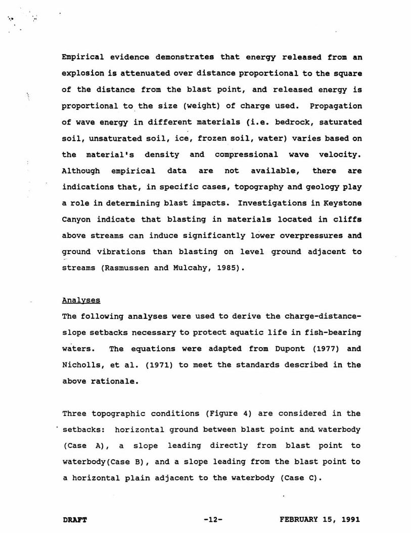
hnpirical evidence demonstrates that energy released from an
explosion is attenuated over distance proportional to the square
of the distance from the blast point, and released energy is
proportional to the size (weight) of charge used. Propagation
of wave energy in different materials (i.e. bedrock, saturated
soil, unsaturated soil, ice, frozen soil, water) varies based on
the material's density and compressional wave velocity.
Although empirical data are not available, there are
indications that, in specific cases, topography and geology play
a role in determining blast impacts. Investigations in Keystone
Canyon indicate that blasting in materials located in cliffs
above streams can induce significantly lower overpressures and
ground vibrations than blasting on level ground adjacent to
streams (Rasmussen and Mulcahy, 1985).
Analvses
The following analyses were used to derive the charge-distance-
slope setbacks necessaryto protect aquatic life in fish-bearing
waters. The equations were adapted from Dupont (1977) and
Nicholls, et al. (1971) to meet the standards described in the
above rationale.
Three topographic conditions (Figure 4) are considered in the
setbacks: horizontal ground between blast point and waterbody
(Case A), a slope leading directly from blast point to
waterbody(Case B), and a slope leading from the blast point to
a horizontal plain adjacent to the waterbody (Case C).
DRAFT FEBRUARY 15, 1991

Case A
case
FIGURE 4. TEREE TOPOGRAPHIC CASES CONSIDERED IN ADF&Q'S PROPOSED BLASTING STANDARDS
Case C
X = Total setback in feet from blast point to high value fish habitat. X is less than 30 feet only when reviewed on a case by case basis.
0 = Angle in degrees between valley floor and blast point. h = Height in feet of center of charge above valley floor.
DRAFT -13- FEBRUARY 15, 1991

For given charge weight and distance, cases A'and B are presumed
to yield identical stream impacts. Where a slope descends
directly to a waterbody, the effect of the blast will be the
same as if on level ground. This is because seismic waves
propagate spherically from the source, irrespective of the slope
and direction (refer to Figure 1).
Case C is treated differently from cases A or B. The
mathematical approach used to calculate these standards assumes
that blast energy reaching the stream decreases as the angle
between the valley floor and the center of charge increases.
That is, the resultant impact on the stream decreases
proportionally with the cosine of the angle between the valley
floor and the center of charge.
The distinction between Case B and Case C is that the distance
between the waterbody and the slope break must be at least
30 feet to meet the criteria of Case C (Figure 4) . The 30 feet
is a safety factor to ensure that there is a sufficient offset
from the waterbody to avoid unpredictable propagation and
refraction of seismic waves. In all three cases (A, B, or C),
the minimum distance between the center of charge and waterbody
for all charge weights is 30 feet. Proposed blasting within 30
feet will be reviewed on a case by case basis.
DRAFT FEBRUARY 15, 1991

Additionally, in Case C situations, the height of the center of
charge above the valley floor (Figure 4) will not be less than
the appropriate distances listed in Tables 5a-5e and 6. These
minimum heights above the valley floor are based on the charge
weight and slope and derive from the equation:
h = 6 sine
Where h = height (feet) of center of charge above valley
floor
W = charge weight (lbs) per interval
0 = Angle (degrees) between valley floor and center
of charge
General Emations
Equation (A) is used to describe the transfer of shock pressure
from the substrate to the water:
Where P, = pressure (lbs/in2) in water
P, = pressure (lbs/in2) . in substrate
2, = acoustic impedance (lbs/ft2-s) of water
Z, = acoustic impedance (lbs/ft2-s) of substrate
DRAFT FEBRUARY 15, 1991

Equation (B) is used to describe the relationship between t
acoustic impedance and the density and velocity of the medium
through which the compressional wave travels:
Where D, = density of water = 62.5 pounds per cubic
foot (lbs/ft3)
D, = density (lbs/ft3) of substrate
C, = compressional wave velocity in water =
4,800 feet per second (ft/s)
C, = compressional wave velocity (ft/s) in
substrate .
The following values were used for D, and C, for various
substrate types:
Rock
. Frozen Soil Ice
Saturated Soil
Unsaturated Soil
lbs / f t3 Sud
165 2.64
DRAFT FEBRUARY 15, 1991

Equation (C) describes the relationship between the peak
particle velocity (V,) and the pressure, density, and
compressional wave velocity in the substrate:
2pr (C) Vr = - DrCr
Equation (D) is known as the scaled distance relationship and is
used to equate the peak particle velocity to charge weight,
distance, and slope:
1 -1.6
(D) Vr = 160( Ji3~0se
Where V, = peak particle velocity (inis)
R = distance (ft) between blast and waterbody
W = charge weight (lbs)
8 = angle (degrees) between valley floor and
blast point
FEBRUARY 15, 1991

Example solution for calculating Case C charge-distance setbacks
to meet 2.7 psi limit for blasting in rock using a 100 pound
charge and a 30° angle between the valley floor and the blast
point.
( 62.5 lbs) ( 4,800 ft
2, - ft3 S 1 1. From equation (B) : - - = 0.1212
zr 165 lbs) ( 15,000 ft ( it3 s 1
P,(1 + 0.12) 2. From equation (A) : P, =
2 (0.12)
. . 3. Limit P, to 2.7psi: P, = inz - - 12.5 lbs
(2) (0.12) in2
4 . Convert psi to gram-centimeters per second squared:
1 g-cm
( 12.5 lbs) ( 4.4482 x lo5 dynes) ( 1 in2 ) (
in2 lbs 6. 4516cm2 s2 dyne
5. From equation (C) :
DRAFT FEBRUARY 15, 1991
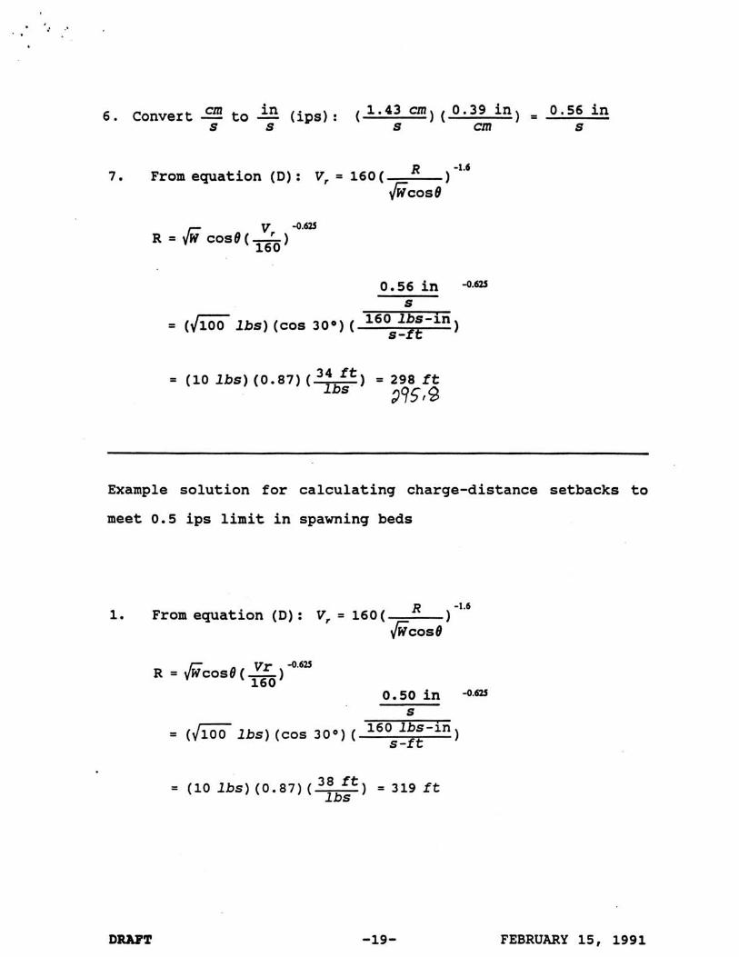
em i n 1 . 4 3 cm) ( 0 . 3 9 i n ) - - 0 . 5 6 in 6 . Convert - to - (ips): ( s s s cm s
1 -1.6
7 . From equation (D) : V, = 160 ( ficose
= (4100 l b s ) (cos 30.) ( lbs-in
s-ft 1
34 ft = (10 l b s ) ( 0 . 8 7 ) (-) lbs = 298 f t 295I8
Example solution for calculating charge-distance setbacks to
meet 0 . 5 i p s limit in spawning beds
1 -1.6
1. From equation (D) : V, = 160 ( ficose
= (JK l b s ) (cos 30') ( 160 lbs - in s-ft 1
38 ft = (10 l b s ) ( 0 . 8 7 ) (-) = 319 f t lbs
FEBRUARY 15 , 1991

TABLE 3: CASE A AND B SETBACKS FROM ANADROMOUS FISH WATERS (2.7 ~ s i Standard) (in feet)l1
Explosive Charge Weight (in pounds)p
Material 1 2 5 10 25 100 500 1000
Rock 34 49 77 109 172 344 769 1088
Frozen Soil 32 45 72 102 161 322 719 1017
Ice 30 4 1 64 9 1 144 288 644 910
Saturated Soil 30 4 1 65 9 1 145 289 647 915
Unsaturated soil 30 30 45 63 100 200 448 633
A/ The straight line distance through the material from the center of the charge to the waterbody, assuming that the blast energy is confined within the material. Uncontained blasts or explosive charges with a detonation velocity of less than 5,000 feet per second will be reviewed on a case-by-case basis.
2/ The scaled distance relationships apply to single shots of a given weight of explosive or single shots in a multiple charge if each charge is separated by an eight millisecond or longer delay. For example, a 500 pound shot on level ground in rock requires a setback distance from a waterbody of 769 feet; a 500 pound shot in rock in charges of 100 pounds each separated byeeight millisecond or longer delays requires a setback distance of 344 feet.

TABLE 4: CASE A AND B SETBACKS FROM SPAWNING BED 10.5.i~~ Stauardl (in feet)ll
Explosive Charge Weight (in pounds)g
All Materials 37 52 82 116 184 368 823 1163
A/ The straight line distance through the material from the center of the charge to the waterbody, assuming that the blast energy is confined within the material. Uncontained blasts or explosive charges with a detonation velocity of less than 5,000 feet per second will be reviewed on a case-by-case basis.
2/ The scaled distance relationships apply to single shots of a given weight of explosive or single shots in a multiple charge if each charge is separated by an eight millisecond or longer delay. For example, a 500 pound shot on level ground in rock requires a setback distance from a waterbody of 823 feet; a 500 pound shot in rock in charges of 100 pounds each separated by eight millisecond or longer delays requires a setback distance of 368 feet.

TABLE 5a: CASE C SETBACKS FROM ANADROMOUS FISH WATERS (2.7 ~ s i Standard) (in feet)ll
Material: Bock
Explosive Charge Weight (in pounds)a
1 2 5 10 25 100 500 1000
Slope 100 34 (0) 48(0) 76(0) 107(1) 169 (1) 339 (2) 758 (4) 1072 (5)
20° 32 (0) 46(0) 72(1) 102(1) 162 (2) 323 (3) 723 (8) 1023 (ll)
30° 30(0) 42 (1) 67(1) 94 (2) 149 (2) 298 (5) 666 (11) 942 (l6)
40° 31(1) 37(1) 59(1) 83 (2) 132 (3) 264 (6) 589 (14) 834 (2Q)
50° 31(1) 31(1) 49 (2) 70(2) 111 (4) 221(8) 495(17) 699 (24)
60° 31(1) 31(1) 38 (2) 54 (3) 86(4) 172 (9) 385(19) 5 4 4 0
80° 31(1) 31(1) 32 (2) 33(3) 35(5) 60 (10) 134 (22) 189 (31)
90° 31(1) 31(1) 32(2) 33 (3) 35(5) 40(10) 52 (22) 62 (32)
(N) = Minimum height in feet of center of charge above valley floor (see text and Figure 4).
/ The straight line distance through the material from the center of the charge to the waterbody, assuming that the blast energy is confined within the material. Uncontained blasts or explosive charges with a detonation velocity of less than 5,000 feet per second will be reviewed on a case-by-case basis.
21 The scaled distance relationships apply to single shots of a given weight of explosive or single shots in a multiple charge if each charge is separated by an eight millisecond or longer delay. For example, a 500 pound shot on a lo0 slope in rock requires a setback distance from a waterbody of 758 feet; a 500 pound shot in rock in charges of 100 pounds each separated by eight millisecond or longer delays requires a setback distance of 339 feet .
,I.

TABLE 5b: CASE C SETBACKS FROM ANADROMOUS FISH W A m S 12.7 D S ~ standard) (in feet)ll
Material: Frozen Soil
~xplosive Charge Weight (in pounds)g
1 2 5 10 25 100 500 1000
Slope lo0 32 (0) 45(0) 71(0) lOO(1) 158 (1) 317 (2) 708 (4) 1001 (5)
200 30 (0) 43 (0) 96(1) 151 (2) 302 (3) 676(8) 955 w) 30° 30 (0) 39 (1) 62 (1) 88(2) 139 (2) 278 (5) 623 (11) 881 (16)
40° 31(1) 35(1) 55(1) 78(2) 123 (3) 246 (6) 551 (14) 779 (20)
50° 31(1) 31(1) 46 (2) 65 (2) 103 (4) 207 (8) 462 (17) 654 (24)
60° 31(1) 31(1) 36(2) 51(3) 80(4) 161 (9) 359 (19) 508 (27)
70° 31(1) 31(1) 32 (2) 35 (3 ) 55(5) 110 (9) 246 (21) 348 (30)
80° 31(1) 31(1) 32(2) 33(3) 35(5) 56 (10) 125 (22) 177 (31)
90° 31(1) 31(1) 32 (2) 33(3) 35(5) 40 (10) 52 (22) 62 (32)
(N) = Minimum height in feet of center of charge above valley floor (see text and Figure 4).
11 The straight line distance through the material from the center of the charge to the waterbody, assuming that the blast energy is confined within the material. Uncontained * blasts or explosive charges with a detonation velocity of less than 5,000 feet per
r UI
second will be reviewed on a case-by-case basis. - # I-' 21 The scaled distance relationships apply to single shots of a given weight oF1"explosive
U) U)
or single shots in a multiple charge if each charge is separated by an eight millisecond c1 or longer delay. For example, a 500 pound shot on a lo0 slope in frozen soil requires
a setback distance from a waterbody of 708 feet; a 500 pound shot in frozen soil in charges of 100 pounds each separated by elght millisecond or longer delays requires a setback distance of 317 feet.

TABLE 5c: CASE C SETBACKS FROM ANADROMOUS FISH WATERS (2.7 D S ~ StandardL (in feet)ll
Material: Ice
Explosive Charge Weight (in pounds)a
1 2 5 10 25 100 500 1000
slope lo0 30(0) 40(0) 63 (0) 90(1) 142 (1) 283 (2) 634 (4) 897 ( 5 )
90° 31(1) 31(1) 32(2) 33 (3) 35(5) 40(10) 52 (22) 62 (ZL)
(N) = Minimum height in feet of center of charge above valley floor (see text and Figure 4).
/ The straight line distance through the material from the center of the charge to the waterbody, assuming that the blast energy is confined within the material. Uncontained blasts or explosive charges with a detonation velocity of less than 5,000 feet per second will be reviewed on a case-by-case basis.
2/ The scaled distance relationships apply to single shots of a given weight of explosive or single shots in a multiple charge if each charge is separated by an eight millisecond or longer delay. For example, a 500 pound shot on a lo0 slope in ice requires a setback distance from a waterbody of 634 feet; a 500 pound shot in ice in charges of 100 pounds each separated by eight millisecond or longer delays requires a setback distance of 283 feet .

a l r 5 4 3
'?t Ez2 W E a l
4 z * . a 6 6.: -4 k u - 4 Q)wrJn 4J4 8 Q ) & Q ) u g g a l & Q) m ? 90~: 0 a 4 m a z 3 u
FEBRUARY 15, 1991

TABLE 5e: C ASE C SETBACKS FROM ANADROMOUS FISH WATERS (2.7 ~ s i Standard1 (in feet)ll
Material:
Explosive Charge Weight (in pounds)#
1 2 5 10 25 100 500 1000
Slope lo0 30(0) 30(0) 4 4 (0) 62(1) 99 (1) 197 (2) 441 (4) 624 (5)
(N) = Minimum height in feet of center of charge above valley floor (see text and Figure 4).
f/ The straight line distance through the material from the center of the charge to the waterbody, assuming that the blast energy is confined within the material. Uncontained blasts or explosive charges with a detonation velocity of less than 5,000 feet per second will be reviewed on a case-by-case basis.
2/ The scaled distance relationships apply to single shots of a given weight of explosive or single shots in a multiple charge if each charge is separated by an eight millisecond or longer delay. For example, a 500 pound shot on a lo0 slope in unsaturated soil requires a setback distance from a waterbody of 441 feet; a 500 pound shot in unsaturated soil in charges of 100 pounds each separated by eight millisecond or longer delays requires a setback distance of 197 feet.

DRAFT FEBRUARY 15, 1991

TABLE 7: SETBACKS FROM SENSITIVE SITES (in feet)
Office of Surface Mining (Code of Federal Regulations, 1990)
Explosive Charge Weight (in pounds) ,I.
Setback (ft) 50 71 112 158 250 550 1230 1739
Setbacks for a given charge weight are calculated with the equation D=w"D,; where D=Distance, in feet, from the blasting point to nearest sensitive site; W=charge weight; Dpscaled distance factor as listed below:
Distance (D) from blaeting eite, Maximum allowable Scaled-distance in feet peak particle factor to be
velocity (Vmax) for applied without ground vibration, seismic monitoring in inchesleecond
0 to 3 0 0 . . . . . . . . . . . . . . . . . . . . . . . . . . 1.25 301 to 5 , 0 0 0 . . . . . . . . . . . . . . . . . . . . . . 1.00 5,001 and beyond......... ......... 0.75

FIGURE 5 *
Setbacks in Various Substrates
ADFaG Case C only (see text and Fig. 4) Setback (f t )
2000 Off ice of Surface Mining Standards
a A A A A A A A 9 - - - - - - -
.. . . . . . . . . . . . . . . . . . . . . . . . . . .. _ .... ............
_. ................. - . ............ . . . . . . . . . . .
0 20 40 60 80 100 Slope (degrees)
Ir Ir - Rock + Frozen Soil -;IC Ice - Saturated Soil Ir
+- Unsat. Soil +- 0.6 ips Std. OSM Std.
See Table 7 for description of OSM standards
Setback for a 1000 pound charge 2.7 psi standards

FEBRUARY 15, 1991 DRAFT

FIGURE 7
Setbacks in Various Substrates 40 Degree Slope
ADFaG Case C only (see text and Fig. 4) Setback (ft)
2000 1 I
0 200 400 600 800 1000 1200 Charge Weight (pounds)
' - Rock ' + Frozen Soil ice' - Saturated Soil ' - Unsat. Soil - 0.5 ips Std. OSM Std.
2.7 psi standards Note that for a 1000 Ibm. oharge, the OSM 'metbaok I m
betwmen 99 and 242% larger than tha A O F I Q retbaokm

References Cited
Alpin, J. A. 1947. The effects of explosives on marine life.
California Fish and Game, 33 (1) : 23-30.
Bishai, H. M. 1961. The effects of pressure on the survival and
distribution of larval and young fish. Zoology Dept. Faculty
of Science, Cairo University, Egypt. pp. 292-311.
Bird, F. H., and K. Roberson. 1984. Keystone Canyon Blasting
Study. Alaska Department of Fish and Game. 25 p.
Christian, E. A. 1973. The effects of underwater explosions on
swimbladder fish. NOLTR 73-103. Naval Ordinance Laboratory,
White Oak, Silver Spring, Maryland. 71 p.
Coastline Environmental Studies, Ltd. 1987. Blast Monitoring of
detonations near marine environment. Project ADFCG. 86.01.
Prepared for: Alaska Department of Transportation and Public
Facilities. Juneau, AK.
Code of Federal Regulations. 1990. Use of Explosives. Title 30,
Pt. 715.19.
Cole, R. H. 1984. Underwater explosions. Princeton University
Press, Princeton, NJ. 437 p.
DRAFT February 15, 1991

Dames & Moore. 1987. Effects of linear explosive seismic energy
releases on fish in Alaska's transition zones. For the Alaska
Oil and Gas Association.
DuPont . August 10, 1977. Letter from M.E. Swanson to
Mr. MacMillan c/o Ferrante Construction Co. Pouch 818, Valdez,
AK 99686. E.I. dupont de Nemours and Company Polymer
Intermediates Dept., Suite 601 400-108th Ave. NE, Bellevue, WA
98004. 4 p.
DuPont. 1980. Blasters' handbook. 16 Edition. Explosives
Products Division, E.I. dupont de Nemours and Company,
Wilmington, Delaware. 494 p.
Falk, M. R., and M. J. Lawrence. 1973. Seismic exploration: Its
nature and effect on fish. Can. Fish. Mar. Serv. Tech. Rep.
CEN-T-73-9. 51 p.
FRED. 1983. Fish culture manual. Alaska Dept. of Fish and Game,
Division of Fisheries Rehabilitation, Enhancement and
Development. Juneau, AK 90p.
Hubbs, C. L., and A. B. Rechnitzer. 1952. Report of experiments
designed to determine effects of underwater explosions on fish
life. California Fish and Game 38: 333-366.
Munday, D. R., G. L. Ennis, D. G. Wright, D. C. Jeffries,
E. R. McGreer, and J. S. Nathers. 1986. Development and
DRAFT -33- February 15, 1991

evaluation of a model to predict effects of buried underwater
blasting charges on fish populations in shallow water areas.
Can. Tech. Rpt. of Fish. and Aquat. ~ c i . 1418.
Nicholls, H. R., C.F. Johnson, and W.I. Duvall. 1971. Blasting
vibrations and their effects on structures. U.S. Department
of the Interior, Bureau of ~ines, Washington D. C. ~ulletin No.
656. 105 p.
Rasmussen, B. 1967. The effects of underwater explosions on
marine life. Bergen, Norway. 17 p.
Rasmussen, D., and P. Mulcahy. 1985. Study of particle velocities
and water overpressures as related to construction blasting
adjacent to anadromous streams. Project F-RF-RS-071-l(25) . Alaska Department of Transportation and Public ~acilities,
Valdez, AK.
Smirnov, A. I. 1954. The effect of mechanical agitation on
developing eggs of the pink salmon (Oncorhvnchus aorbuscha)
(Walbaum) Salmonidae. Dokl. Adad. Nauk. SSSR, 97 (2) : 365-368.
(Transl. from Russian by Fish. Res. Board Can. Transl. Ser.
No. 231, 1959).
Smirnov, A. I. 1955. The effect of mechanical agitation at
different periods of development on the eggs of autumn chum
salmon (Oncorhvnchus keta infrasp. autumnalis Berg,
Salmonidae) . Dokl. Adad. Nauk. SSSR, 105 (4) : 873-876.
DRAFT -34- February 15, 1991

(Transl. from Russian by Fish. Res. Board Can. Transl. Ser.
NO. 230, 1959).
Trasky, L. L. 1976. Environmental impact of seismic exploration
and blasting in the aquatic environment. Alaska Dept. of Fish
and Game. Unpubl. Rep. 18 p.
Wright, D. G. 1982. A discussion paper on the use of explosives
in the marine waters of the Northwest Territories. Dept. of
Fisheries and Oceans, Winnipeg. 48 p.
Yelverton, J. T., D.. R. Richmond, W. Hicks, K. Sanders, and E. R.
Fletcher. 1975. The relationship between fish size and their
response to underwater blast. Defense Nuclear Agency, Dept.
Defense, Washington D.C. Topical Rep. DNA 3677 T. 42.
DRAFT February 15, 1991